

Page 1
Interchange
INTERCOM PHONE BRIDGE
User Guide
™
JK Audio
Page 2

Welcome
Thank You
Thank you for purchasing a JK Audio Interchange™ Intercom Phone Bridge.
Please read this guide for instructions on setting up and using your new product.
Getting Assistance
If you have technical or application questions:
In the US & Canada, call us toll free at: 800-552-8346
All other countries dial: 815-786-2929 (M-F 8:30-5:00pm Central Time Zone)
Email us at: support@jkaudio.com
Or, check out our FAQ section for answers to common questions.
Limited Warranty
The Interchange is covered by a 2-Year Warranty to be free from defective
workmanship and materials. To obtain service, contact JK Audio by phone or
email for return authorization. Once authorized, you will carefully pack and ship
the faulty product and all accessories to us. You will pay for shipping to us and
we will pay for return back to you.
This warranty does not cover damages due to accident, weather, re, ood,
earthquake, misuse, unauthorized repairs or modications, or damages occurred
in shipping, only defective workmanship or materials.
THERE ARE NO EXPRESSED OR IMPLIED WARRANTIES WHICH EXTEND BEYOND THE
WARRANTY HERE MADE.
Interchange™ Intercom Phone Bridge
ii
Page 3

Contents
Contents
Overview 1
Getting to know your Interchange™
2 Controls and Indicators
4 Inputs & Outputs
Getting Connected
5 Intercom
5 Mobile Device
6 Single Line Phone
7 Multi-Line Phone
Operation 8
Technical Information 10
2
5
Contents
iii
Page 4

Features
Male And Female 3 Pin
XLR Intercom Loop Jacks
Male And Female 3 Pin
XLR 4-Wire Jacks
Male XLR Mix Line Out for Monitoring
Send and Receive LED Metering
Front Panel Screwdriver
Level Controls
Front Panel Channel Select
Front Panel Mobile Phone Interface
Listen Always,
Talk When Talk-Enabled
Intercom and Phone Hybrid Powered
Interchange™ Intercom Phone Bridge
iv
Page 5

Overview
Introducing the Interchange™
Interchange allows remote access to your party line intercom through select
JK Audio POTS and VoIP phone hybrids. This professional half rack interface
provides a four wire audio interface and remote control connection for JK Audio
innkeeper LTD, innkeeper 1x/1rx™, or innkeeper 2™ Digital Hybrids for POTS
lines. Likewise, couple a JK Audio PBXport™ with an Interchange™ for PBX/
VoIP lines, or connect a JK Audio AutoHybrid IP2™ for VoIP or AoIP connections.
The front panel headset interface jack allows easy connection of your mobile
phone, tablet, or computer allowing remote access through a wireless phone or
conferencing app.
Interchange contains a sophisticated intercom hybrid in a low noise pro audio
design. The Listen-Always design allows both the phone hybrid / 4-wire
connection and the mobile phone headset interface to monitor the intercom just
like any other belt pack. Listen mode is a high impedance bridging tap on the
intercom line. Talk mode is enabled via a front panel switch, either Off, On, or
Auto. Auto follows the phone hybrid Auto-Answer mode. Talk mode uses a solid
state relay to properly couple Talk audio from the phone line and mobile phone
interfaces, to the intercom channel.
The Innkeeper 2 and AutoHybrid IP2 conference features allows two callers to
share one intercom connection. Alternatively, the included cables allow Line 1
and Line 2 of the Innkeeper 2 or AutoHybrid IP2 to be connected to two separate
Interchange units, allowing connection to separate intercom loops.
Overview
1
Page 6

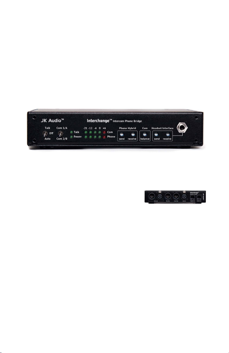
Getting to Know Your Interchange
2 531
4
6
7 8 9 10 11 12
Controls & Indicators
1. Talk Control
The position of the three position toggle switch determines when
Interchange will send audio into the Party Line intercom.
Up = Talk: Interchange sends and receives audio (simultaneously). Use this
position with the headset interface, or as a general purpose 4-wire interface.
Center = Off: Interchange functions as a listen-only device. No audio will be
sent into the Party Line intercom.
Down = Auto: Talk function follows the hook state of the innkeeper Phone
Hybrid.
2. Intercom Channel
Up = Audio on Intercom Channel 1/A (Pin 2)
Down = Audio on Intercom Channel 2/B (Pin 3)
3. Talk LED
Indicates audio transmission into the Party Line intercom.
4. Power LED
Indicates intercom power detected.
5. COM Level LEDs
Indicates audio signal power on/from the Intercom channel. The 0dB LED
corresponds to a nominal level of -10 dBu on the intercom channel.
Interchange™ Intercom Phone Bridge
2
Page 7

Getting to Know Your Interchange
Controls Cont’d
6. Phone Level LEDs
Indicates audio signal power on/from the phone interface.
7. Phone Hybrid Send Level
Adjusts audio signal level going to the phone hybrid / 4-wire interface.
8. Phone Hybrid Receive Level
Adjusts audio signal level coming from the phone hybrid / 4-wire interface.
9. Com Balance
Fine tuning for the intercom hybrid function. Optimizes separation
between send and receive when pushing audio into the intercom with the
Talk function.
10. Headset Interface Send Level
Adjusts audio signal level to the mobile device.
11. Headset Interface Receive Level
Adjusts audio signal level coming from the mobile device.
12. Headset Interface Jack
Connect to the headset jack of your mobile device with supplied
interface cable.
Getting to Know Your Interchange™
3
Page 8

Getting to Know Your Interchange
1 5 63 42
Inputs & Outputs
1. Party Line Intercom Jack
Connect to one or two channel 3-pin unbalanced Party Line
intercom system.
2. Mix Out XLR Jack
Contains a line level mix of both the phone and intercom audio.
3. Line Out Jack
Line level audio output from the intercom to the phone hybrid or
audio device.
4. Line In Jack
Line level audio from the phone hybrid to the intercom.
5. Single Line Remote Jack
Connects to JK Audio single line digital hybrids.
6. Multi-Line Remote Jack
7. Connects to JK Audio multi line digital hybrids.
Interchange™ Intercom Phone Bridge
4
Page 9

Getting Connected
Start by Connecting to the Intercom
1. Set the Talk switch to the Off position, and the Com switch to the desired
channel.
2. Connect Interchange to your intercom network using one or both of the
Intercom XLR jacks.
3. As soon as Interchange becomes connected to the intercom system, the
Power LED will light, and the Com LEDs will indicate any audio signal
present on the intercom channel.
If using a Mobile Device (If using a phone line, please skip to page 6.)
1. Connect one of the supplied mobile device adaptor cords between the front
panel Headset Interface jack and your mobile phone headset jack.
2. Using your mobile phone, place a call to a remote location. You should be
able to immediately monitor the intercom signal from the remote location.
3. Adjust the Headset Interface Send level control for desired signal level at the
remote location.
4. Change the Talk toggle switch to the Talk position to allow the remote
location to be heard on the intercom channel.
5. The return audio path from the remote location into the intercom can be
adjusted two ways. The front panel Headset Interface Receive level control
provides adjustment suitable for most mobile devices. However, most mobile
devices also have a headphone level control which works along with the
Interchange controls.
6. It is best to set the headphone level on your mobile device rst, then set
the level on Interchange for nal adjustment. This signal will appear on
the Interchange Phone LEDs. Not necessarily on the Com LEDs. Monitor
receive levels by listening on an intercom belt pack.
Com Balance with Headset Interface
Interchange features an active hybrid to separate the unbalanced 2-wire
wire intercom audio channel into separate (4-wire) send and receive
audio paths. While nominal separation is achieved with typical operation,
the separation can be ne tuned if the intercom loop offers additional
challenges. Perform the tuning operation when the intercom network is
not in use. Using your mobile device, play or generate a xed level tone or
white noise into the intercom system. Adjust the signal level to 0 dB on the
Interchange Phone LED display. Be sure that the Talk control switch is in
the Talk position. Adjust the Com Balance control while observing the Com
LEDs, to nd the minimum (the position where the fewest Com LEDs are lit).
Remove the test signal and proceed with normal operation.
Getting Connected
5
Page 10

Getting Connected
Single Line Phone Hybrids
Connect the supplied cables as follows for innkeeper LTD or innkeeper 1x/1rx:
1. INTERCHANGE Line Out XLR to the HYBRID’S Send input XLR.
2. INTERCHANGE Line In XLR to the HYBRID’S Caller out XLR.
3. Using the supplied 10 pin RJ50 cable, connect the INTERCHANGE Single-Line
Remote jack to the INNKEEPER Remote control jack.
4. Set the INNKEEPER rear panel Send level switch to Line Level.
5. Connect the INNKEEPER to an analog phone line or VoIP analog phone
line port.
PHONE LINES
Line Phone
PUSH
innkeeper LTD
Auto
Caller
Answer
PUSH PUSH
www.jkaudio.com
Send
Line OutMix OutIntercom Line In
JK Audio, Inc.
Remote
9 VDC
Cente r(+)
RJ-50
TM
Interchange
Remote Control
Single-Line Multi-Line
INNKEEPER LTD
JK Audio
INTERCHANGE
TM
Interchange™ Intercom Phone Bridge
6
Page 11

Getting Connected
100-2 40 VAC
50-60 Hz, 2.5 A
1
Remote
Line 1Line 2
Caller Send Caller Send Master
Send
PUSH PUSH PUSH
100-2 40 VAC
50-60 Hz, 2.5 A
Multi-Line Phone Hybrids
Connect the supplied cables as follows:
1. innkeeper 2: Line 1
1. INTERCHANGE (1) Line Out XLR to the HYBRID’S Send 1 input XLR.
2. INTERCHANGE (1) Line In XLR to the HYBRID’S Caller 1 output XLR.
3. Using the supplied 10 pin RJ50 cable, connect the INTERCHANGE (1)
Multi-Line Remote jack to the INNKEEPER 2 Remote control jack.
4. Connect INNKEEPER 2 Line 1 to an analog phone line or VoIP analog phone
line port.
2. innkeeper 2: Line 2
1. INTERCHANGE (2) Line Out XLR to the HYBRID’S Send 2 input XLR.
2. INTERCHANGE (2) Line In XLR to the HYBRID’S Caller 2 output XLR.
3. Using the supplied 10 pin RJ50 cable, connect the INTERCHANGE (1)
Single-Line Remote jack to the INTERCHANGE (2) Single-Line Remote
control jack.
4. Connect INNKEEPER 2 Line 2 to an analog phone line or VoIP analog phone
line port.
PHONE LINES
Line 2 Line 1
Aux
Line
Line Aux
PUSH PUSH PUSH
1
Caller Send Caller Send Master
PUSH PUSH
PUSH PUSH
Line 1Line 2
Line OutMix OutIntercom Line In
Line OutMix OutIntercom Line In
Send
Interchange
Remote Control
Single-Line Multi-Line
Interchange
Remote Control
Single-Line Multi-Line
RJ-50
TM
TM
Remote
RJ-50
JK Audio
TM
JK Audio
TM
INNKEEPER 2
INTERCHANGE (1)
INTERCHANGE (2)
Getting Connected
7
Page 12

Operation
Operation with Phone Hybrids
1. Place the Interchange Talk switch in the Off position. Apply power to the
phone hybrid and place a call from a remote location. You should be able to
immediately monitor the intercom signal from the remote location.
2. Adjust the phone hybrid Send level and interchange Phone Hybrid Send
level controls for desired signal level at the remote location.
3. Change the Talk toggle switch to the Auto position to allow Interchange to
follow the call status of the phone hybrid. During an active call, the remote
location can now be heard on the intercom channel.
4. The return audio path from the remote location into the intercom can be
adjusted using the digital hybrid ‘Caller’ level and Interchange ‘Receive’
level controls. This signal will appear on the Interchange Phone LEDs. Not
necessarily on the Com LEDs. Monitor receive levels by listening on an
intercom belt pack.
5. Changing the Talk switch to Off returns the system to a remote Listen-Only
conguration.
Com Balance with Phone Hybrids
Interchange features an active hybrid to separate the unbalanced 2-wire wire
intercom audio channel into separate (4-wire) send and receive audio paths.
While nominal separation is achieved with typical operation, the separation can
be ne tuned if the intercom loop offers additional challenges. Perform the tuning
operation when the intercom network is not in use. Using the Test Tone function
on innkeeper 1x or innkeeper 2, adjust the signal level to 0 dB on the Interchange
Phone LED display (innkeeper LTD does not have a test tone feature, therefore
an alternate tone generator must be used). Be sure that the Talk control switch
is in the Talk position. Adjust the Com Balance control while observing the Com
LEDs, to nd the minimum (the position where the fewest Com LEDs are lit).
Remove the test signal and proceed with normal operation.
Interchange™ Intercom Phone Bridge
8
Page 13

Operation
9
Page 14

Technical Information
Specications
Intercom Channel
Connection Male & Female 3-pin XLR
Output Level -10 dBu (250 mV RMS) nominal
Terminating Impedance 200 ohms
Bridging Impedance >15k ohms
Pin 1 Common
Pin 2 Audio + 30 VDC (+12 VDC min) 50 mA
Pin 3 Audio
Input
Balanced Female XLR 20k ohms / 500 mV RMS (-4 dBu nom) +12 dBu max
Output
Balanced Male XLR 200 ohms / 500 mV RMS (-4 dBu nom) +12 dBu max
Size 7.75” x 6.5” x 2.3”
Weight 2.1 lbs (960 g)
Interchange™ Intercom Phone Bridge
10
Page 15

Interchange Block Diagram
JK Audio Interchange
Simplified Block Diagram
July 2, 2013
Mix
Out
Intercom
1/A
2/B
Technical Information
Intercom
Hybrid
Intercom
Meter
Phone
Receive
Headset Interface
Receive
Headset
Emulator
Com
Limiter
Send
Meter
Send
ON
Talk Control
Control
RJ50: INN2
OFF
Logic
AUTO
Control
Remote
RJ45:INN1/INNLTD
XLR Line
Input
XLR Line
Output
Hybrid / 4-Wire Interface
Block Diagram
11
Page 16

Interchange
INTERCOM PHONE BRIDGE
User Guide Version 5/8/14
JK Audio, Inc.
1311 E 6th St.
Sandwich, IL 60548
United States
Telephone: 815.786.2929
Toll Free: 1.800.jkaudio
Fax: 815.786.8502
www.jkaudio.com
© 2014 JK Audio, Inc. All rights reserved.
™
JK Audio
 Loading...