

Page 1
JK Audio
User Guide
innkeeper 2/4
™
Digital Hybrid
Page 2

ii
innkeeper 2/4™ Digital Hybrid
Thank You
Thank you for purchasing a JK Audio innkeeper 2/4 Digital Hybrid. Please read
this guide for instructions on setting up and using your new product.
Getting Assistance
If you have technical or application questions:
In the US & Canada, call us toll free at: 800-552-8346
All other countries dial: 815-786-2929 (M-F 8:30-5:00pm Central Time Zone)
Email us at: [email protected]
Or, check out our FAQ section for answers to common questions.
Limited Warranty
The innkeeper 2/4 is covered by a 2 year warranty to be free from defective
workmanship and materials. To obtain service, contact JK Audio by phone or
email for return authorization. Once authorized, you will carefully pack and ship
the faulty product and all accessories to us. You will pay for shipping to us and
we will pay for return back to you.
This warranty does not cover damages due to accident, weather, re, ood,
earthquake, misuse, unauthorized repairs or modications, or damages occurred
in shipping, only defective workmanship or materials.
There are no expressed or implied warranties which extend beyond the
warranty here made.
Warnings & Safety Precautions
• Read and keep these instructions.
• Heed all warnings.
• Follow all instructions.
• Clean only with a soft dry cloth.
• Do not install near any heat sources such as radiators, heat registers, stoves,
or other apparatus (including ampliers) that produce heat.
• Do not defeat the safety purpose of the three-prong grounding type plug.
If the provided plug does not t into your outlet, consult an electrician for
replacement of the obsolete outlet.
• Do not use this unit if the electrical power cord is frayed or broken. The power
cord should be routed so that it is not likely to be walked on or pinched by
items placed upon or against it.
• To reduce the risk of re or electric shock, do not expose this apparatus to rain
or moisture.
• Refer all servicing to qualied service personnel.
Welcome
Page 3

Contents
Overview 1
Getting to know your innkeeper 2/4
2 Controls & Indicators
4 Inputs & Outputs
2
Remote Terminal Block
5
Getting Connected
6
Menu Navigation
8
Serial Port Interface
10
Conference
12
Optional Remote Control 13
FAQs 14
Technical Information 15
Contents
iii
Contents
Page 4

iv
innkeeper 2/4™ Digital Hybrid
16 bit DSP Technology
Auto-Answer (Switchable On/Off)
Proprietary Auto Null Algorithm
(50 dB null)
Conferencing (innkeeper 2 only)
1 kHz Tone Generator
Menu with Backlit LCD Display
Alpha-Numeric Keypad
Memory/Speed Dial
Send XLR Line Inputs (2/4)
Master Send XLR
Caller XLR Line Outputs (2/4)
Monitor Handset Jacks
Remote Control via RS-232
RIU-IP Remote IP Interface
Send and Caller Signal Level LEDs
Send and Caller Volume Controls
Features
Detachable North American
Power Cord
CN081 Serial Port Cord
RJ11 Phone Cord
What’s in the Box?
Features
Page 5

Overview
1
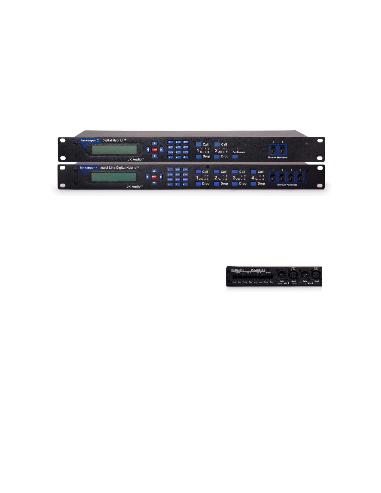
Introducing the innkeeper 2/4™
Innkeeper 2 and innkeeper 4 will allow you to send and receive audio over
analog telephone lines. While this may seem like a simple task that any
telephone can do, the challenge is getting the best quality audio from such a
miserable audio path.
What is a Digital Hybrid?
The innkeeper 2/4 digital hybrids connect audio signals to a standard analog
telephone line without the variations in quality found with analog hybrids. The
main function of a hybrid is to bring in the caller’s voice from the phone line as
clear and clean as possible. In the real world, when you send your voice down
the telephone line it has a tendency to bleed over into the caller’s audio. The
hybrid must adapt to the phone line in order to properly separate transmit and
receive audio. We use a 16 bit DSP (Digital Signal Processor) to continuously
monitor the phone line and local audio signals to deliver excellent trans-hybrid
loss, also known as separation. Our dual-convergence algorithm can achieve
excellent separation, typically exceeding 50 dB.
Ready to go?
The innkeeper 2/4 controls and connectors are clearly marked and ready for
operation. If this is your rst exposure to a hybrid, we suggest that you read the
entire manual to allow you to take advantage of all these features.
Any Questions?
Before you pick up the phone... Please thumb through the rest of this manual.
You might nd those deep technical questions are covered on later pages.
Overview
Page 6
2
innkeeper 2/4™ Digital Hybrid
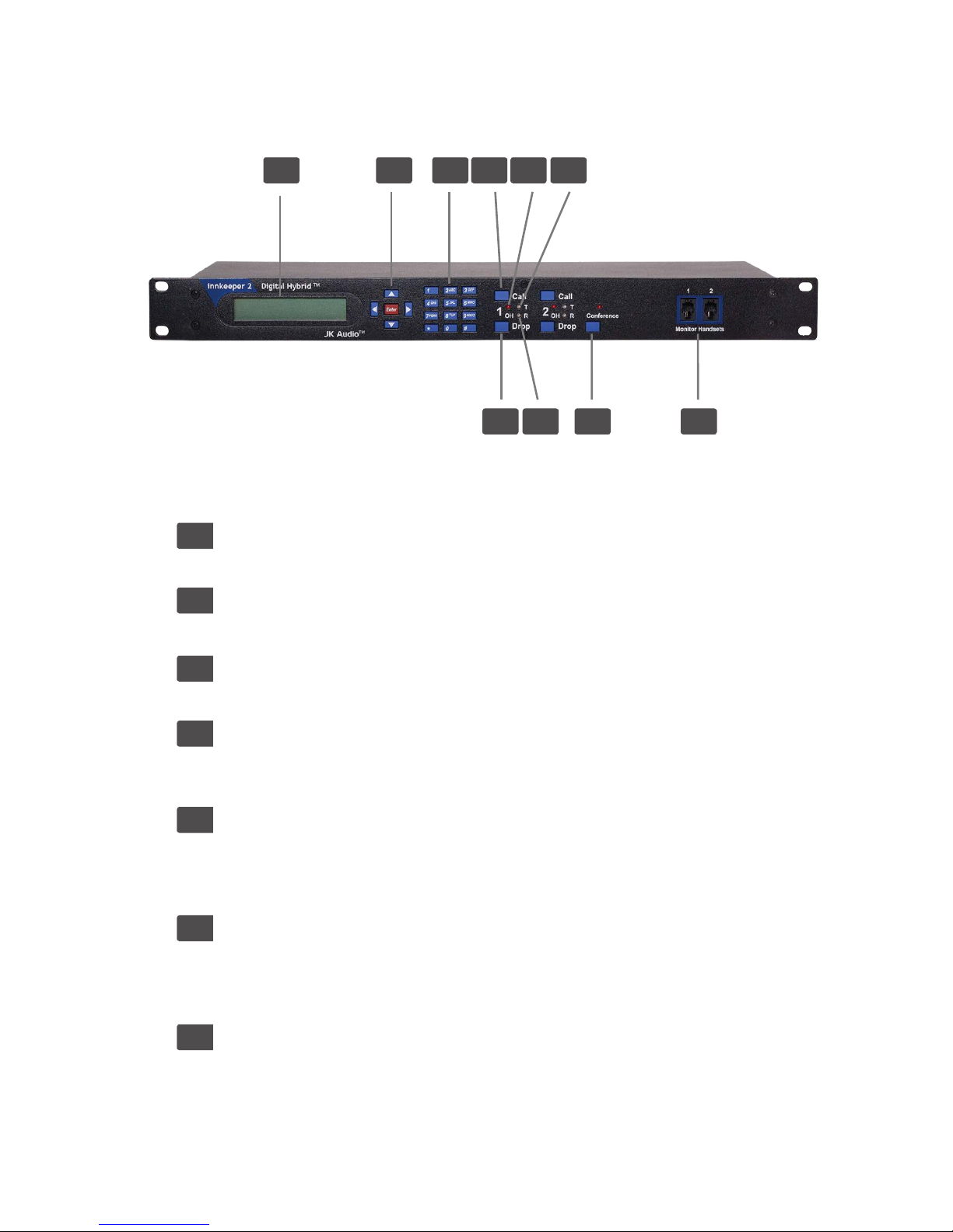
Getting to Know Your innkeeper 2/4
3 4 5 61 2
7 8 9 10
1. Menu Display
Backlit LCD, 2x20 characters.
2. Directional Control Pad
Navigate the menu. Press <Enter> to make a selection.
3. Numeric Keypad
Dial a number or manually enter menu selection codes.
4. Call Buttons
Takes the corresponding line off-hook; press this button to answer a call or
you can direct a call from your aux phone through the hybrid.
5. OH LED
Lit when the corresponding line is off-hook or on line with a call. Also
functions as a ring indicator and will icker when ring voltage is present on
the corresponding phone line.
6. Transmit LED
Bi-color Transmit LED will light green when audio is being sent down the
corresponding phone line at -20 dB or greater signal level.
LED will change to red to indicate clipping at -3 dB.
7. Drop Buttons
Press this button to drop (hang up) a call or place the correspnding phone
line on-hook.
Controls & Indicators
Page 7

Controls & Indicators
3
Getting to Know Your innkeeper 2/4
Indicators Cont’d
8. Receive LED
Bi-color Receive LED will light green when audio is received from the
corresponding phone line at -20 dB or greater signal level.
LED will change to red to indicate clipping at -3 dB.
9. Conference Button
Conference lines 1 & 2 together when both lines are off-hook.
This feature is available on innkeeper 2 only.
10. Monitor Handset Jacks
Connect an Electret type handset for communication on the
corresponding phone line.
Transmit Signals
The goal is to drive the phone line at high enough levels to avoid phone line
noise, but not so loud as to cause excessive clipping. Adjust your <Send> audio
signals to a level slightly less than the point where you see occasional ashes of
red on the Transmit LED. These ashes should occur during loud speech bursts
only. If the Transmit LED stays lit red for extended periods, you can assume
that much of your speech is being clipped or distorted. In this case you should
lower the audio levels for the signal that is causing the clipping. The innkeeper
2/4 menu will also allow you to adjust your input levels in 1 dB increments over a
+/-10 dB range.
Receive Signals
The innkeeper 2/4 menu will allow you to adjust individual Caller output levels in
1 dB increments over a +/-10 dB range to give you the best signal level at your
equipment. The Caller level control in the menu will not change what you see on
the Receive LED.
Auto-Answer
The Auto-Answer feature can be activated through the innkeeper 2/4 menu. You
may select which phone lines will have auto-answer enabled as well as how
many rings before autoanswer. When Auto-Answer is enabled, you can still take
calls manually using the call button. When nished, you can either drop the call
manually or allow the call to auto-disconnect. Innkeeper 2/4 will look for a CPC
disconnect signal or ROH message from the phone company to determine when
a call has disconnected. This can take up to a minute.
Page 8
4
innkeeper 2/4™ Digital Hybrid
Getting to Know Your innkeeper 2/4
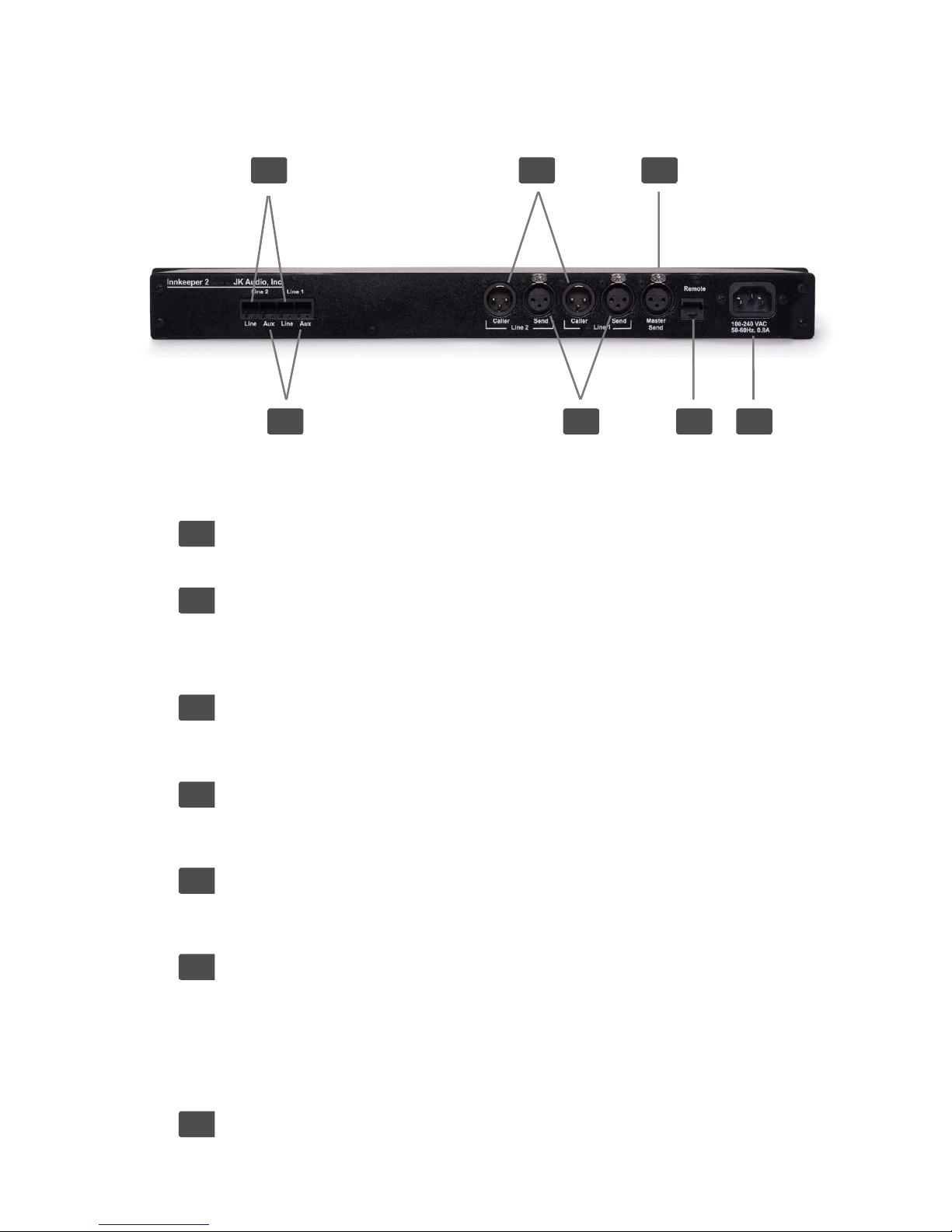
Inputs & Outputs
1. Phone Line
Connect to a standard, single line, analog telephone line.
2. Aux Phone
Connect a single line analog telephone for call setup / dialing, or producer
call screening. Telephones connected will only work with the corresponding
phone line.
3. Caller Output
Male balanced line level XLR output contains only the callers voice from the
corresponding phone line.
4. Send Input
Female balanced line level XLR input for signals going into the
corresponding telephone line. Mic or line level input.
5. Master Send
Female balanced line level XLR input sends audio to any or all of the phone
lines based upon controls set within the menu.
6. Remote Control Jack
10 pin RJ-50 modular jack for connection to:
A. RS-232 Cable (Included)
B. JK Audio RIU-IP Remote Interface
C. Remote Terminal Block (Included). See page 5.
D. JK Audio Concierge Switch Core (Not compatible with innkeeper 4.)
7. Power Jack
Universal AC power input for 100-240 Volt, 50-60 Hz supply current.
3 51
2 4 6 7
Page 9

Inputs & Outputs
5
Remote Terminal Block
Remote Jack
The 10 pin RJ-50 jack on the back of the innkeeper 2/4 provides a proprietary
connection to the supplied remote terminal block. A 1-meter cable is provided for
this connection. This jack can also be used to connect to the optional JK Audio
RIU-IP remote interface unit (page 12).
Remote Terminal Block
The Remote Terminal Block includes an Off-Hook signal pin and a Call/Drop
control pin for each phone line channel. The OH signal pin is current limited to 50
mA, 5 VDC. The control pin toggles the corresponding phone line off-hook/onhook with a connection/break from ground.
This terminal block was designed to allow remote off-hook/on-hook control and
status for each phone line. The innkeeper 2 model also provides on/off control
and status for the Conference feature. Use only the included RJ-50 cable to
connect the Remote Terminal Block to the <Remote> jack on the innkeeper 2/4.
Connecting the Line OH Control pin to the Ground pin will take the line off-hook,
breaking this contact will release the line and disconnect the call.
The OH Status pin will provide 5V, 50mA current when the corresponding line is
off-hook. You can use this pin to drive a relay, light an LED, etc.
Terminal Block Pinout
1 2 3 4 5 6 7 8 9 10
GRD L1-ST L1-CNT L2-ST L2-CNT L3-ST L3-CNT L4-ST L4-CNT GRD
Terminal Description
1: Ground
2: Line 1: OH Status Signal
3: Line 1: OH Control
4: Line 2: OH Status Signal
5: Line 2: OH Control
6: Line 3: OH Status Signal
7: Line 3: OH Control
8: Line 4: OH Status Signal
9: Line 4: OH Control
10: Ground
Page 10

6
innkeeper 2/4™ Digital Hybrid
Setting Up
Although each application will require a slightly different setup, following is a
general cable conneciton setup and explanation.
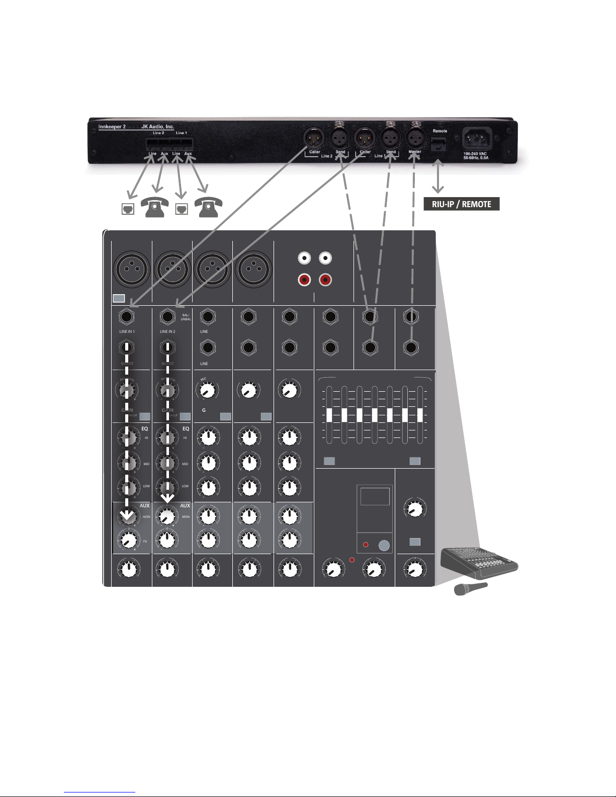
1. Connect the supplied RJ-11 phone line cable(s) between the jack marked
<Line> and your wall jack(s). Be sure these jacks supports standard single
line analog telephone operation. The innkeeper 2/4 will not work with "dry
pair" phone line connections
2. Connect to your mixer using the Mix-Minus method. See Figure 7a.
A mix-minus signal is an audio signal that contains a mix of your local
microphones plus any other audio, minus the Caller’s own voice. Sending
the Caller’s audio back to the innkeeper 2/4 will cause an echo, or feedback.
1. Connect a line-level audio signal to the innkeeper 2/4 <Send> jack(s):
a. <Send> jack(s): Audio will only be sent down the
corresponding line.
b. <Master Send> jack: Audio will be sent down either or both phone
lines based upon your selections in the menu. Each caller output
jack will contain audio only from its corresponding phone line.
2. Connect the <Caller> jack to a line-level input(s) on your
mixing console. Local audio and audio from alternate phone lines will
not be present on these jacks. Innkeeper 2 has the ability to send
isolated caller audio, mixed caller audio, or mixed caller and local audio
from the Caller XLR depending on selections made in the Conferencing
menu.
For whichever input channel you have the <Caller> connected to on
the mixer, turn the corresponding <Aux> control to minimum. All other
<Aux> controls should be set for audio sent to the phone line. Each
<Aux Send> bus is completely separate from all other outputs, so
these Aux controls will not affect what is heard on the Main outputs or
on any other Aux buses. We recommend using an <Aux Send> bus
that is pre-fader, so you can use the fader controls to set the levels
of each channel to the main output without affecting what is sent to
the phone line. If your mixer does not have an <Aux Send> bus, you
can use <Pan> controls with the Left and Right outputs. Pan all the
microphones, etc. to the Left output and pan the Caller to the Right
output. Then connect only the <Left> output to the innkeeper 2/4
<Send>. Or, you may use an external Mix-Minus box that will create
this signal for you.
3. Connect the supplied AC power cord to the back of the innkeeper and then
to an AC power outlet.
Your innkeeper 2/4 is now ready to take calls. You may want to connect an
auxiliary telephone to the innkeeper <Aux> jack so you can dial out and set up
calls, or use the <Auto-Answer> feature to answer incoming calls.
Getting Connected
Page 11
MIC
1 2 3/4 5/6 7/8
MIC MIC MIC
L L
R R
TAPE
IN
UNBALANCED
MAIN
METERS
USB
INPUT LEVEL L R
TAPE
OUT
INSERT
LINE IN 1 LINE IN 2
BAL/
UNBAL
BAL/
UNBAL
MONO MONO MONO MONO
POWER
BAL/
UNBAL
BAL/
UNBAL
HI
MID
LOW
BAL/
UNBAL
BAL/
UNBAL
BAL/
UNBAL
BAL/
UNBAL
LINE IN 3
LINE IN 4
LINE IN 5
LINE IN 6
LINE IN 7
LINE IN 8INSERT
ST RETURN
GAIN
EQEQEQEQ
AUX
PAN
PAN PAN PAN PAN
FX MASTER FX TO MON PHONES TAPE LEVEL
AUX AUX AUX AUX
EQ
GAINGAINGAINGAIN
FX SEND
MON SEND FOOTSWITCH
MAIN OUT PHONES
PHANTOM
POWER
STEREO GRAPHIC EQ
15
10
5
0
5
10
15
125 250 500 1K 2K 4K 8K
15
10
5
0
5
10
15
48V
M
I
C
G
A
I
N
M
I
C
G
A
I
N
M
I
C
G
A
I
N
M
I
C
G
A
I
N
U
LOW CUT LOW CUT LOW CUTLOW CUT
OL
15
10
6
3
0
2
4
7
10
30
20
HI
MID
LOW
HI
MID
LOW
HI
MID
LOW
HI
MID
LOW
MON
FX FX FX FX FX
MUTE
PRESETS
MON MON MON MON
U
U
U
U
00
U
-
+
-
+
-
+
-
+
-
+
-
+
-
+
-
+
-
+
-
+
-
+
-
+
-
+
-
+
-
+
-
+
-
+
-
+
-
+
-
+
-
+
-
+
-
+
-
+
-
+
-
+
-
+
-
+
-
+
-
+
U
U
U
U
U
U
U
U
U
U
U
U
U
U
U
U
U
U
U
U
U
U
U
U
U
RL
U
RL
U
RL
U
RL
U
RL
7
Getting Connected
RIU-IP / REMOTE
Figure 7a
Getting Connected
Auxiliary Telephone
innkeeper 2/4 does not disconnect the auxiliary telephone when you press the
<Call> button. You can use an auxiliary phone to place or screen a call and then
place it on hold. When you are ready to take the call on innkeeper 2/4, simply
press the <Call> button. Your telephone will automatically release the hold. If you
need to take the call back on the aux telephone, simply pick up the telephone
handset before the innkeeper 2/4 <Drop> button is pressed.
Page 12

8
Backlit Menu Display and Controls
The innkeeper 2/4 menu is controlled by the directional arrows, alpha numeric
keypad and <Enter> button. You may use either the arrow keys to scroll through
the menus or the keypad to directly select menus and use the <Enter> button
or the keypad to make your selections. Through the menu you have access to
the following. The (#,#) indicates the numeric entry used to access these menus
without scrolling. For example, to access the Call History View (2,1)
menu
directly, you would press: 2, <Enter>, 1, <Enter>.
Phone Book (1) A 50 entry name and number phone book for storing
speed dial numbers.
Phone Book View (1,1) Allows you to view name and phone numbers
of added entries. You may dial the selected entry from this menu by simply
pressing the Call button on any phone line.
Phone Book Add Entry (1,2) You may add new entries from this
menu. After pressing <Enter> you will be prompted for the phone number.
You may enter a 2 second pause in your phone number entry by pressing
the ">" key. Multiple ">" key presses will enter multiple 2-second pauses.
The display will show a "." between the numbers for each 2-second pause
entered. After the <Enter> key is pressed again you will be prompted for
the entry Name. Alpha characters may be selected by using the multi-tap
feature. For example, to enter the character "a" you would press the <2>
key. To enter "b" you would press the <2> key twice. Hitting a new key, the
Next ">" key or waiting 2 seconds will accept the current character and
move the cursor forward. See page 10 for multi-tap key legend.
Phone Book Delete Entry (1,3) Entries may be deleted individually
from this menu. You will be prompted to conrm delete of an entry.
Phone Book Clear (1,4) Press enter from this menu to clear all phone
book entries. You will be prompted to conrm your intent to clear the entire
phone book before deletion.
Call History (2) Calls you place will automatically be entered into the Call
History menu. The Call History menu will hold up to 16 numbers.
Call History View (2,1) Allows you to view name and phone numbers of
automatically added entries. You may dial the selected entry from this menu
by simply pressing the <Call> button on any phone line.
Call History Clear (2,2) Press <Enter> from this menu to clear all
automatically added history entries. You will be prompted to conrm your
intent to clear the entire call history before deletion.
Cong. (3) This menu allows you to control Auto-Answer, Auto-
Disconnect, Audio Levels, Master Send, Calibration and Restore Factory
Default or Custom Settings.
innkeeper 2/4™ Digital Hybrid
Menu Navigation
Page 13

Menu Navigation
9
Cong. Auto-Answer (3,1) Here you can congure Auto-Answer.
Cong. Auto-Answer On/Off (3,1,1) This menu allows you to turn
Auto-Answer on and off for each line independently or for all lines.
Cong. Auto-Answer Ring Count (3,1,2) Select the number of
rings before the unit auto-answers on each line individually or on all lines.
Cong. Audio Levels (3,2) Audio levels for each phone line input and
output can be set here. The Audio Levels menu allows you to adjust levels of
audio in 1dB increments over a +/- 10dB range. You may adjust the levels of
the Send inputs as well as the Caller outputs.
Cong. Audio Levels Send (3,2,1) Send input levels can be set for
each line individually or all lines. These settings affect the independent Send
input as well as the Master Send for the selected line(s).
Cong. Audio Levels Caller (3,2,2) Caller output levels can be set
here for each line independently or all lines.
Cong. Master Send (3,3) This menu gives you the ability to turn the
Master Send on or off for each line individually or all phone lines.
Cong. Calibration (3,4) Here you can send a 1kHz test tone down the
phone line(s) and the output jacks. You may turn the tone on or off for each
line individually or for all lines. This is not required for setting the null. This
tone is only for your convenience in setting your equipment audio levels.
Conference (3,5) innkeeper 2 Only This menu allows you to
congure settings for the Conference feature. (see page 11).
Conf. Send Mix Mode (3,5,1) innkeeper 2 Only Congure the
Send Mix Mode to "Send Mix" default or "No Mix" (page 11).
Conf. Caller Mix Mode (3,5,2) innkeeper 2 Only Congure
the Caller Mix Mode to "No Mix" default, "Caller Mix" or "Full Mix Minus"
(page11).
Cong. Presets (3,6) With this menu you can save and restore custom
presets or reset the unit to factory default presets.
Cong. Presets - Default (3,6,1) Here you may restore factory default
presets. You will be prompted to conrm Factory Reset after selecting this
option.
Cong. Presets - Custom (3,6,2) Here you may save and restore
custom presets based upon your current conguration.
Menu Navigation
Page 14

10
innkeeper 2/4™ Digital Hybrid
Menu Navigation
Multi-Tap Key Legend
These character sets are active only when entering the Name of your phone
book entry. While entering the phone number you will not have access to alpha
characters.
Control Keys: < Clear last character
> Next/Accept current character
* Shift (press before each uppercase entry)
# Space
Character Keys: 1 . @ ? ! -
/ , & : |
2 a b c 2
3 d e f 3
4 g h i 4
5 j k l 5
6 m n o 6
7 p q r s 7
8 t u v 8
9 w x y z 9
ASCII Command Remote Control
The ASCII commands listed on the following page can be entered through the
serial port on your computer by using the DB9 connector on the RIU.
Any terminal emulation program on your computer, such as HyperTerminal, can
be accessed using these parameters:
Baud Rate Stop Bits Parity Flow Control
9600 1 None None
All commands begin with the ‘/’ character, and will be automatically executed on
next ‘/’ or <Enter>.
The line number is set to ‘1’ by default and is changed by using the ‘Lx'
parameter with the specied control command.
x species the line number (1 to 4).
v species the parameter value to be used for the command.
y species the digit string used during manual dialing mode.
Status information is automatically returned during incoming state changes for
the specied line number for the following line conditions: on-hook, off-hook,
incoming ring, and line hold.
Page 15

11
Serial Port Interface
Conference
Serial Remote Control Commands
Command Feature Value Description
/AT or //
Version Status Returns product version and status.
/?
Help Status Returns Help Menu to screen.
/ST
Cong Status Returns option conguration settings.
/LxSTv
Line State
On-hook= 0
Off-hook= 1
Ring= 2
Hold= 3
Returns state information for the specied line
Esc
Escape Escape current command before execution.
/VBv
Verbose
0
1
2
3
VB0: No Echo of Response
VB1: Abbreviated Echo
VB2: Abbreviated Echo
VB3: Full Echo
/LxCL
Call Line
Off-hook line control for each line.
/LxDR
Drop Line
On-hook line control for each line.
/LxAAv
Auto
Answer
Off=0
On=1
Activate/deactivate auto-answer mode for
each line.
/LxARv
Ring
Count
RING CNT= v
Set auto-answer ring count from 1-7 rings per
line (default is 3).
/LxHDv
Line Hold
Off=0
Hold=1
Place specied line on hold or release hold.
/LxSLv
Send
Level
-10 to +10
Set send (transmit) audio level for specied line
from -10 to +10dBu.
/LxRLv
Receive
Level
-10 to +10
Set caller (receive) audio level for specied line
from -10 to +10dBu.
/LxDIy
Dial
Phone
Number
Digit String
Dial phone number on selected line, up to 20
digits (line will automatically go off-hook).
/CNv
Conference
Off=0
On=1
innkeeper 2 only. Conference both phone lines
together (both lines must be off-hook rst)
/PBv
Phone Book
Upload /
Download
UPLD=0
DNLD=1
Upload/download entire phonebook entry list
(20 characters per name and 20 digits per
phone number for each entry) from/to ASCII le
on user PC and innkeeper 2/4.
/PEv
Phone Book
View / Add /
Delete Entry
TBD Manipulate individual phone book entries.
/LxMSv
Master Send
Off=0
On=1
Activate/deactivate Master Send mode for
each line.
Page 16

12
innkeeper 2/4™ Digital Hybrid
Conference
Conference
One press of the <Conference> button will join the audio paths of both Line 1
and Line 2, provided there are calls present on both lines. A second press of
the <Conference> button will break the audio paths between the calls. An autodropped or manually dropped line will automatically break the conference. By
default, Line 1 <Send> and Line 2 <Send> audio will be mixed together digitally
and sent into both phone lines. Line 1 caller will hear Line 2 caller audio. Line 2
caller will also hear Line 1 caller audio. In the menu, this conguration is referred
to as Send-Mix, Caller-No Mix. This default conguration is by far the most
widely used. Advanced options are available for Conference mode; however for
most situations it will not be necessary to change these default options.
Innkeeper 2 Advanced Conference Options
The factory default conference mode provides both callers with a mix of Line 1
<Send> and Line 2 <Send> audio. Additional mix options can be found in the
Conguration menu. These options allow you to enable and disable <Send> and
<Caller> mix features. Keep in mind that no matter what options are selected,
both callers will always be able to communicate with each other in Conference
mode.
Send = Mix (default)
Line 1 <Send> and Line 2 <Send> audio is mixed and sent to both Callers.
Send = No Mix
Line 1 <Send> audio to Caller on Line 1.
Line 2 <Send> audio to Caller on Line 2.
Caller = No Mix (default)
Caller 1's voice/audio will only be on the Line 1 <Caller> output XLR.
Caller 2's voice/audio will only be on the Line 2 <Caller> output XLR.
<Send> audio will not be present on these outputs.
Caller = Caller Mix
Callers 1 and 2 voice will be mixed on both <Caller> XLR outputs.
<Send> audio will not be present on these outputs.
Caller = Full Mix Minus
A full mix of all audio on each of the caller XLR outputs, minus the <Send>
audio for that phone line.
Line 1 <Caller> XLR contains Caller 1 + Caller 2 + <Send> 2.
Line 2 <Caller> XLR contains Caller 1 + Caller 2 + <Send> 1.
Page 17

FAQs
13
Optional Remote Interface
RIU-IP (Sold Separately)
This remote control interface was designed for use with innkeeper 1x/1rx as well
as JK Audio innkeeper 2 and innkeeper 4 digital hybrids. This unit contains a web
server which allows the user to send and receive control data through their web
browser. RIU-IP can be connected to the user’s computer NIC card for direct
control, to a switch or hub for network control, or to an Ethernet port with internet
access for control from anywhere in the world.
RIU-IP Features and capabilities when used with innkeeper 2/4:
• RJ-45 Ethernet port
• RS-232 remote control port with simple ASCII protocol
• No external power required
• Indication of incoming ring per line
• On-Hook and Off-Hook
• Place call on hold or release hold.
• Dial (number) (line).
• Auto-Answer: On / Off, set ring count
• Test tone start / stop per line
• Audio level - Send and Receive
• Master Send on/off
• Phone Book updates
• Conference Mode on/off (innkeeper 2 only)
Page 18

14
innkeeper 2/4™ Digital Hybrid
FAQs
FAQs
1. Can I plug a mic into one of the female XLR jacks?
No, these are Line-Level inputs only.
2. How do I adjust signal levels?
Use menu settings to change input and output levels ±10dB.
3. How do I know what rmware my innkeeper 2/4 is running on
and how can I update it?
Contact [email protected] for possible rmware updates.
4. What happens to the phone connection if power is
momentarily interrupted?
FCC and International telecom rules require that we drop the connection if
power is lost for any period of time. We strongly suggest that you use a low
cost, computer style UPS system if uninterrupted service is required.
5. Does the innkeeper2/4 use a line polarity reversal to drop a
call automatically?
No, innkeeper 2/4 does not use line polarity reversal as means of
dropped-call detection.
Page 19

Input Impedance / Level
Balanced Female XLR:
20k ohms /
500 mV RMS; -4 dBu nom.; +10 dBu max
Output
Balanced Male XLR:
200 ohms / 500 mV RMS; -4 dBu nom.;
+10 dBu max; Caller Only
Handset:
Front panel handset jacks biased for
electret handset (not included)
Misc
Phone Line: RJ11C
Aux Phone: RJ11C
Ringer: 0.8B REN
Isolation: 1500 VAC
Frequency Response: Telephone Side 200 Hz-3.6 kHz
Power: 120-240 VAC Power Supply
Size: 1.75" x 7.3" x 19" (4.5 x 18.6 x 48.3 cm)
Weight: 7.2 lbs (3.2 kg)
Specications
Technical Information
15
Technical Information
Page 20
16
innkeeper 2/4™ Digital Hybrid
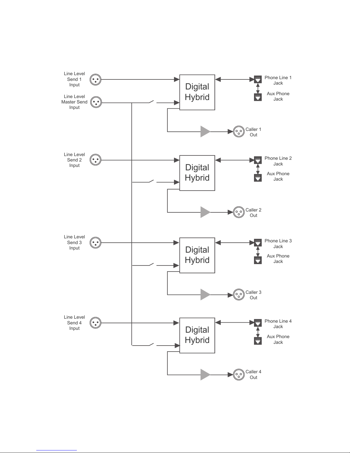
Block Diagram
Digital
Hybrid
Digital
Hybrid
Digital
Hybrid
Digital
Hybrid
Line Level
Send 1
Input
Line Level
Master Send
Input
Line Level
Send 2
Input
Line Level
Send 3
Input
Line Level
Send 4
Input
Phone Line 1
Jack
Aux Phone
Jack
Caller 1
Out
Phone Line 2
Jack
Aux Phone
Jack
Caller 2
Out
Phone Line 3
Jack
Aux Phone
Jack
Caller 3
Out
Phone Line 4
Jack
Aux Phone
Jack
Caller 4
Out
Block Diagram
Page 21

Declaration of Conformity
17
Declaration of Conformity
Manufacturer’s Name:
Manufacturer’s
Address:
JK Audio, Inc.
1311 E 6
th
Street
Sandwich, Illinois 60548 USA
Declares that the product:
Product Name:
Model Numbers:
innkeeper 2/4 Two-Line/Multi-Line Digital Hybrid
innkeeper 2/4
Conforms to the following Product Specications:
Safety:
ESD:
Emissions:
Telecom:
EN 60950 / AS/NZS 60950:2000
CAN/CSA-C22.2 No. 60950-01-03
EN 55024:1998; EN 61000-3-2; EN 61000-3-3
EN 55022:1998
AS/NZS CISPR 22 (2002)
FCC Part 15, Subpart B
ICES-003
AS/ACIF S002:2001
FCC CFR 47, Part 68
The product herewith complies with the requirements of the following Directives and
carries the CE marking accordingly:
LVD 2006/95/EC (Safety)
R&TTE 1999/5/EC (Telecom)
EMC 89/336/EEC (EMC)
RoHS Directive 2002/95/EC
The Technical File containing supporting documentation is maintained at:
JK Audio, Inc (Corporate Headquarters)
Compliance Manager
1311 E 6th Street
Sandwich, Illinois 60548 USA
815-786-2929 phone
815-786-8502 fax
Declaration of Conformity
Page 22

18
innkeeper 2/4™ Digital Hybrid
FCC Registration
Your new JK Audio product has been registered with the Federal Communications
Commission (FCC). This product complies with the standards in Part 68 of the
FCC rules.
1. Connection and use with the nationwide telephone network
The FCC requires that you connect this telephone equipment to the national telephone
network through a USOC RJ-11C modular telephone jack. This equipment may not be
used with Party Line Service or Coin Telephone Lines. This equipment is hearing aid
compatible.
2. Information for the telephone company
Upon request from your local telephone company, you are required to provide the
following information:
A. The “line” to which you will connect the telephone equipment (that is, your
telephone number), and
B. The telephone equipment’s FCC registration number.This can be found on the
bottom of your telephone equipment, and,
C. The ringer equivalence number (REN) for this equipment. The REN is used
to determine the quantity of devices which will be connected to the telephone
line. Excessive RENs on the telephone line may result in the devices not
ringing in response to an incoming call. In most, but not all areas, the sum of
the RENs should not exceed 5.0. To be certain of the number of devices that
may beconnected to the line, as determined by the total RENs, contact the
local telephone company.
3. Repair Instructions
If it is determined that your telephone equipment is malfunctioning, the FCC requires
that it not be used and that it be unplugged from the modular outlet until the problem
has been corrected. Repairs to this telephone equipment can only be made by the
manufacturer or its authorized agents or by others who may be authorized by the
FCC. For repair procedures, follow the instructions outlined under the warranty section
of the manual.
4. Rights of the telephone company
If telephone equipment is causing harm to the network, the telephone company may
temporarily discontinue your telephone service. If possible, they’ll notify you before
they interrupt service. If advanced notice isn’t practical, you’ll be notied as soon as
possible. You’ll be given the opportunity to correct the problem, and you’ll be informed
of your right to le a complaint with the FCC. Your telephone company may make
changes in its facilities, equipment, operations or procedures that could affect the
proper functioning of your JK Audio product. If such changes are planned, you’ll be
notied by your telephone company.
FCC Registration
Page 23

FCC Compliance Notice
19
FCC Part 15 Subpart A Compliance
This equipment has been tested and found to comply with the limits for a Class A
digital device, pursuant to Part 15 of the FCC Rules. These limits are designed to
provide reasonable protection against harmful interference when the equipment is
operated in a commercial environment. This equipment generates, uses, and can
radiate radio frequency energy and, if not installed and used in accordance with
the instruction manual, may cause harmful interference to radio communications.
Operation of this equipment in a residential area is likely to cause harmful interference
in which case the user will be required to correct the interference at his/her own
expense.
Changes or modications not expressly approved by JK Audio can void the user’s
authority to operate the equipment.
FCC Compliance Notice
Page 24

JK Audio, Inc.
1311 E 6th St.
Sandwich, IL 60548
United States
Telephone: 815.786.2929
Toll Free: 1.800.jkaudio
Fax: 815.786.8502
www.jkaudio.com
© 2014 JK Audio, Inc. All rights reserved.
innkeeper 2/4™
Digital Hybrid
User Guide Version 8/11/15
JK Audio
 Loading...