

Page 1
Warranty
Inline Patch is covered by a 2 year warranty to be free from
defective workmanship and materials. In the event that the
Inline Patch needs repair, you must call us to get an authorization, and then carefully pack and ship it to us. You
will pay for shipping to us and we will pay for return back to
you, UPS ground. No free repairs will be made if the defect
was caused by misuse, weather conditions, or other cause,
except for defective workmanship or materials. THERE
ARE NO EXPRESSED OR IMPLIED WARRANTIES
WHICH EXTEND BEYOND THE WARRANTY HERE
MADE.
INLINE
PATCH
Telephone Audio Interface
4/07
JK Audio, Inc. 1311 E 6th Street, Sandwich, IL 60548 USA
Voice: (815) 786-2929 Toll Free: 800-JK-Audio Fax: 815-786-8502
Info@jkaudio.com www.jkaudio.com
Copyright © 2007 JK Audio. All Rights Reserved.
User Guide
JK Audio
Page 2
Description
FCC Registration (continued)
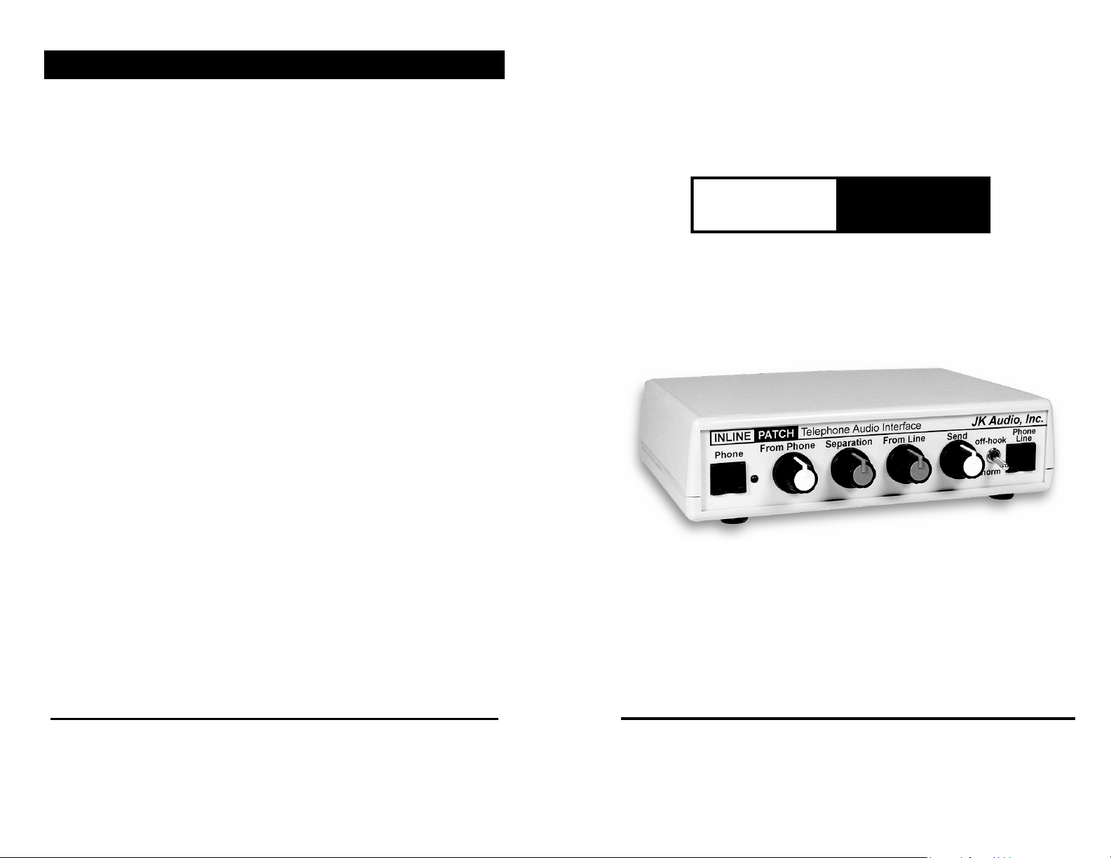
The Inline Patch gives you access to the audio from both
sides of your telephone call. Simply install this little box
“inline” between the telephone wall jack and the base of your
telephone. You can use any single-line residential (analog)
corded or cordless telephone or if available the data / modem
port on a digital or PBX telephone. Add a pair of powered
speakers and everyone in the room will hear both sides of the
conversation. Separate volume controls ensure that both
sides of the call are heard at the same level. Inline Patch is
not the same as a speakerphone. Only the person with the
telephone handset can talk while everyone else listens in.
You can pass around the handset with more control over
your teleconference or IVR demo.
You can also use Inline Patch to add audio to your conversation, or send audio into the phone line instead of your voice.
3. Repair Instructions
If it is determined that your telephone equipment is mal-
functioning, the FCC requires that it not be used and
that it be unplugged from the modular outlet until the
problem has been corrected. Repairs to this telephone
equipment can only be made by the manufacturer or its
authorized agents or by others who may be authorized
by the FCC. For repair procedures, follow the instructions outlined under the warranty section of the manual.
4. Rights of the telephone company
If telephone equipment is causing harm to the network,
the telephone company may temporarily discontinue
your telephone service. If possible, they'll notify you before they
interrupt service. If advanced notice isn't practi-
cal, you'll be notified as soon as possible. You'll be
given the opportunity to correct the problem, and you'll
be informed of your right to file a complaint with the
FCC.
Your telephone company may make changes in its fa-
cilities, equipment, operations or procedures that could
affect the proper functioning of your JK Audio product.
If such changes are planned, you'll be notified by your
telephone company.
2
11
Page 3
FCC Registration
Connection
Your new JK Audio product has been registered with the
Federal Communications Commission (FCC). This product
complies with the standards in Part 68 of the FCC rules.
1. Connection and use with the nationwide telephone
network
The FCC requires that you connect this telephone
equipment to the national telephone network through a
USOC RJ-11C modular telephone jack.
This equipment may not be used with Party Line Service
or Coin Telephone Lines.
This equipment is hearing aid compatible.
2. Information for the telephone company
Upon request from your local telephone company, you
are required to provide the following information:
a) The "line" to which you will connect the telephone
equipment (that is, your telephone number), and
b) The telephone equipment's FCC registration number.
This can be found on the bottom of your telephone
equipment, and,
c) The ringer equivalence number (REN) for this equip-
ment.
The REN is used to determine the quantity of de v i c e s
which will be connected to the telephone line. Excessive
RENs on the telephone line may result in the devices
not ringing in response to an incoming call. In most, but
not all areas, the sum of the RENs should not exceed
5.0. To be certain of the number of devices that may be
connected to the line, as determined by the total RENs,
contact the local telephone company.
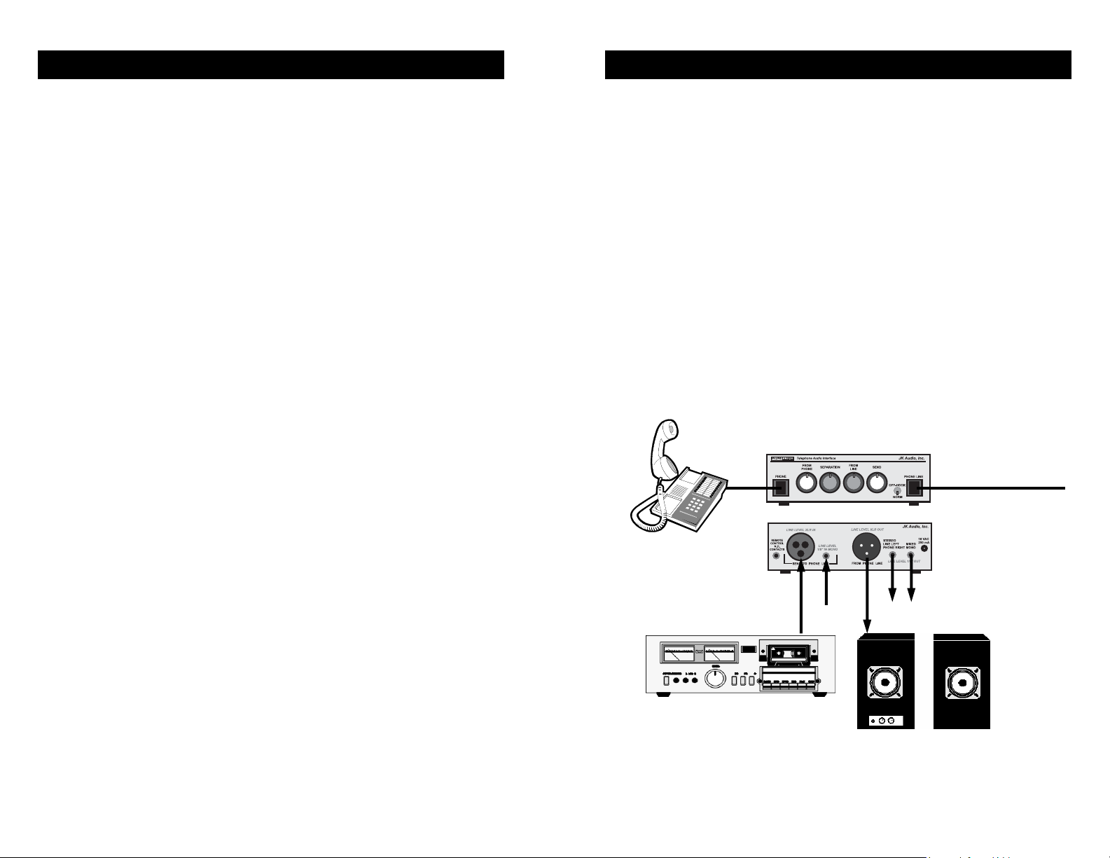
Setup for use with residential / analog telephones:
1. Unplug the telephone cord from the base of your telephone.
2. Plug that telephone cord into the jack on the Inline Patch
marked “Phone Line”.
3. Using the telephone cable we have provided, plug one
end into your Inline Patch marked ‘Phone” and the other
end of the cable into your telephone.
4. Connect your audio equipment to the 3.5mm and / or XLR
line input and output jacks on the Inline Patch.
5. Connect the power supply to the back of the Inline Patch.
Inline Patch
To analog RJ11
Wall Jack
Analog Telephone
Audio Equipment
To send audio into
phone line
Powered Speakers or audio
equipment to receive audio
from phone line
10
3
Page 4
Connection (continued)
FAQ’s
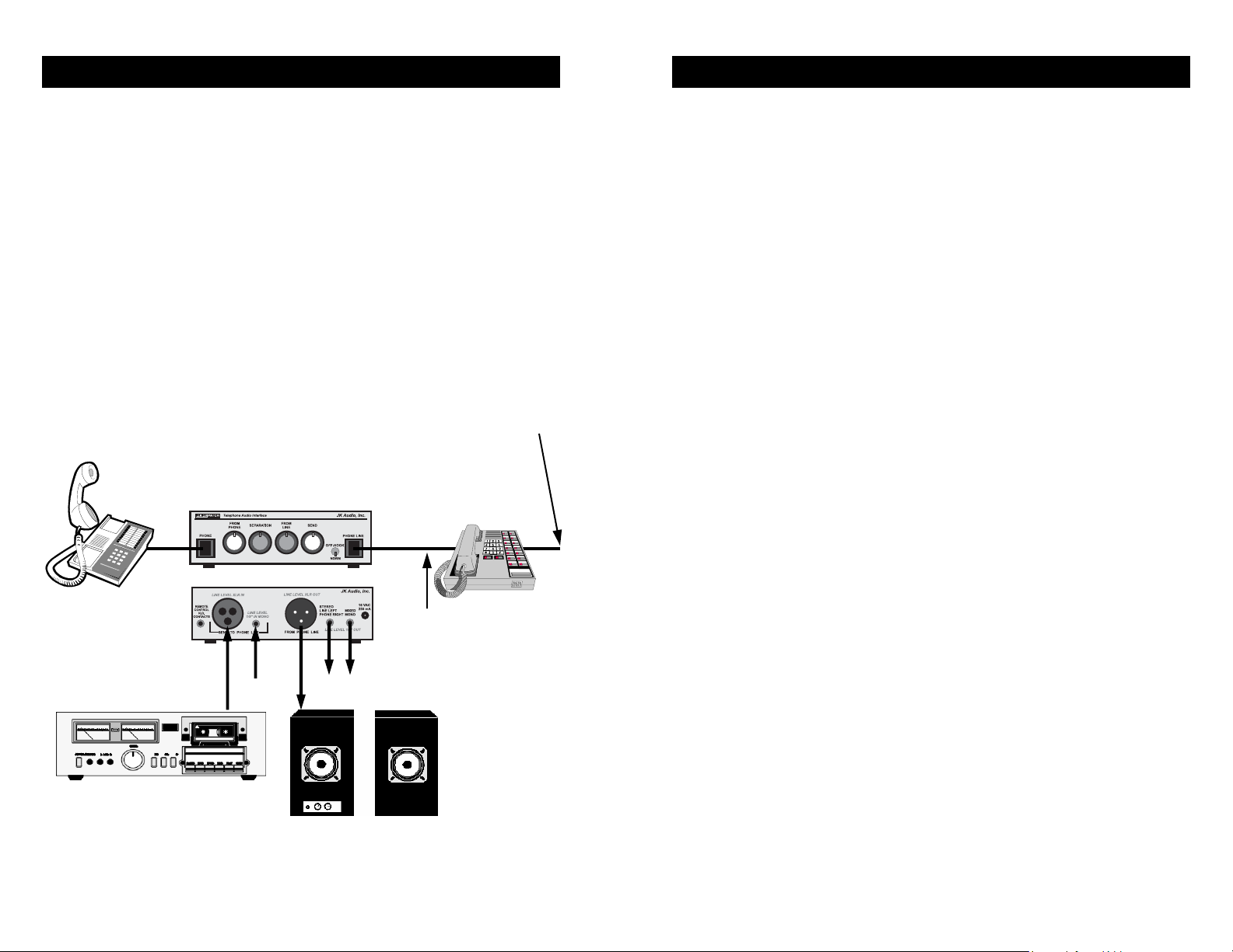
Setup for use with PBX phone systems:
Setup for use with PBX phone systems is the same as for
analog telephones with one exception. Instead of connecting
the Phone Line jack of the Inline Patch to a wall jack, you will
connect to the data / modem jack on your PBX phone. You
will still need a regular analog telephone connected to the
Phone jack of the Inline Patch. When dialing out you will
need to take the necessary steps to get a direct connection to
the main analog phone line (example: dialing 9 + 1 + phone
number). You will not physically use your PBX phone while
operating the Inline Patch. It simply acts as your connection
to the telephone line. Dialing, speaking, etc. will be done
through the separate analog telephone.
Analog Telephone
Inline Patch
To digital or
PBX Wall Jack
Digital or PBX
Telephone
To Data /
Modem Port
on phone
? I'm using a CD player with an Inline Patch to send audio
down the phone line and then recording that audio with
the caller's comments. The CD audio is overpowering the
caller audio even when I turn the "From Phone" control all
the way down. What's wrong?
! The "From Phone" control only adjusts the output of your
voice that is sent through your telephone. The audio you
are feeding into the inputs on the back of the Inline Patch
comes back mixed with the caller's voice. The Inline Patch
does not attempt to separate audio sent into the inputs,
only your voice sent through your telephone. You'll have
to lower the "Send" level on the Inline Patch to correct this
problem.
? Can I connect the Inline Patch directly to my multi-line,
PBX or ISDN phone system wall jack?
! NO! Connecting the Inline Patch to anything other than
a single line POTS (analog) phone line or emulated
analog phone line could irreversibly damage the unit.
If you do not know what type of phone line you have,
it is best to err on the side of caution and not connect
it. Call our technical support department and we will
assist you. Page 4 of this user guide illustrates how you
may use the Inline Patch if you do not have an analog line.
Audio Equipment
To send audio into
phone line
Powered Speakers or audio
equipment to receive audio
from phone line
4
9
Page 5

FAQ’s
Operation
? There is a small amount of hum in the background of my
recordings made from the Inline Patch. What’s wrong?
! Try turning up the “From Line” volume control knob to
around 2:00. That should decrease line resistance and
help eliminate the hum.
? I recently purchased the Inline Patch, which works great,
but I don't seem to be getting as much volume out of the
XLR output as promised in your catalog. What's wrong?
! Check your XLR Cable. Some Sound Engineers are in the
habit of connecting the "ground wire" (pin 1) and the
"negative wire" together. This is sometimes done to convert transformer output signals into a single ended output.
Inline Patch uses an active differential output so grounding one of the hot pins will drop the output in half. Separate these two wires and you should hear a difference.
? There is a hum on the output of my Inline Patch, even
when nothing else is connected. What else could it be?
! Make certain you are using the power supply that was
shipped with the unit. Power supplies are not all the
same.
? We purchased an Inline Patch to take callers on our radio
show. It functions just as promised but we've now found
that 20 dB of separation really isn't enough for us. What
can we do?
! The Inline Patch was designed primarily for interview re-
cording and telecom demos. If you're looking for something to put callers on the air for a radio show you should
purchase a digital hybrid instead. Our Broadcast Host and
innkeeper 1x digital hybrids typically provide greater than
50 dB separation between send and receive and have
great sound quality.
Output Jacks
The Inline Patch has three audio output jacks on the back
panel. The 3.5 mm stereo jack has the phone line audio on
the left channel and your voice on the right channel. The second 3.5 mm jack has both sides of the call combined on both
left and right channels. You may use either a mono or stereo
plug in this jack. The third output is a balanced male XLR
jack. The XLR jack contains only the audio coming from the
phone line with a nominal 20 dB of trans-hybrid loss (your
voice will be mixed with the caller’s audio, but about 20 dB
lower).
There are three output controls on the front of the Inline
Patch. From Phone adjusts the level of your voice on both
output mini jacks. From Line adjusts the level of the audio
coming from the phone line on all three output jacks.
The Separation control is used to achieve t he best match between your voice and the audio coming from the phone line.
When you send your voice into the phone line it comes back
to you mixed in with the audio from the other side of the call,
although it will be about 20 dB lower than your original transmit level. This means that if your audio is sent at 0 dB, and
you receive the caller’s audio at –10 dB, then you would have
10 dB of separation between your voice and the caller audio.
The goal is to have a minimum amount of your voice coming
back to you from the phone line.
To fine tune the separation, first connect your audio equipment (powered speakers, mixer with a VU meter, etc.) to the
mixed mono output jack on the back of the Inline Patch. Next
turn the From Phone control all the way down and the From
Line control all the way up. Now place a phone call. Without
any audio coming from the other end of the call, hold down a
touch tone on your telephone while adjusting the Separation
control to find the most quiet position. Now turn the From
Line control to about 12:00 and use the From Phone control
8
5
Page 6

Operation (continued)
Specifications
The hybrid circuitry in the Inline Patch can provide a nominal
20 dB of transmit / receive isolation. When using the stereo
jack with stereo speakers, the 20 dB isolation will give you
substantial left / right separation. The separation on FM stereo is typically around 20 dB.
Send Side (To Phone Line)
The Inline Patch includes a balanced female XLR jack and a
3.5mm (1/8”) mono mini jack to send audio to the telephone
line. These jacks can be connected to an audio output such
as the headphone output jack on a tape recorder, or the line
output of a PC audio card, CD player or audio mixer.
If you want to use a microphone to add extra audio to the
call, you will first need to add an amplifier to your microphone
so that the signal is boosted to line level. You can use both
the XLR and the mini jack input at the same time, and add it
to the audio coming from the handset microphone. The level
of the audio you send through the input jacks into the phone
line can be adjusted with the Send control. Note that this audio will come back mixed with the caller audio, so be sure not
to overpower the caller’s voice with your own audio.
Off Hook - Norm Switch
This switch allows you to seize the phone line without using a
telephone. The switch should be set to “Norm” to dial out using a telephone. Set the switch to “Off-Hook” to seize the line
and answer an incoming call without using a telephone. This
switch can be remotely operated using your own switch contacts connected to the N.O. Contacts jack on the back of the
unit. Simply wire a 3.5 mm plug to a normally open switch. A
short across tip and ring on a stereo plug will take the phone
line off-hook. You can also use a 3.5 mm mono plug.
Note: Seizing the phone line activates the internal circuitry of
the Inline Patch, essentially “turning it on”. The green LED on
the front panel only indicates that the unit is receiving power.
Inputs (to phone line):
Balanced Connector Female XLR
Input Impedance 1 k ohms
Level 250 mV RMS (-10 dBm nom.)
Line Connector 1/8” (3.5mm) mono mini jack
Input Impedance 20 k ohms
Level 250 mV RMS (-10 dBm nom)
Outputs:
Balanced Connector Male XLR
Output Impedance 50 ohms
Level 500 mV RMS (+12 dBm max.)
Stereo Connector 1/8” (3.5mm) stereo mini jack
Output Impedance 50 ohms
Level 250 mV RMS (+12 dBm max.)
Mono Connector 1/8” (3.5mm) stereo mini jack
Output Impedance 50 ohms
Level 250 mV RMS (+12 dBm max.)
Remote:
Connector 1/8” (3.5mm) TRS stereo jack
Connect tip to ring to go Off-hook
Phone line:
Connector RJ11C
Isolation 1500 volts
Phone:
Connector RJ11C
Voltage 32 VDC
6
7
 Loading...