

J&J Electronics Color Splash, Color Splash LPL-F1C, Color Splash LPL-S1C Installation And Operation Manual
Technical Support
Phone: 800.735.4553 ext. 242
For more information about this or other J&J Electronics lighting products,
please visit www.jandjpoolspa.com
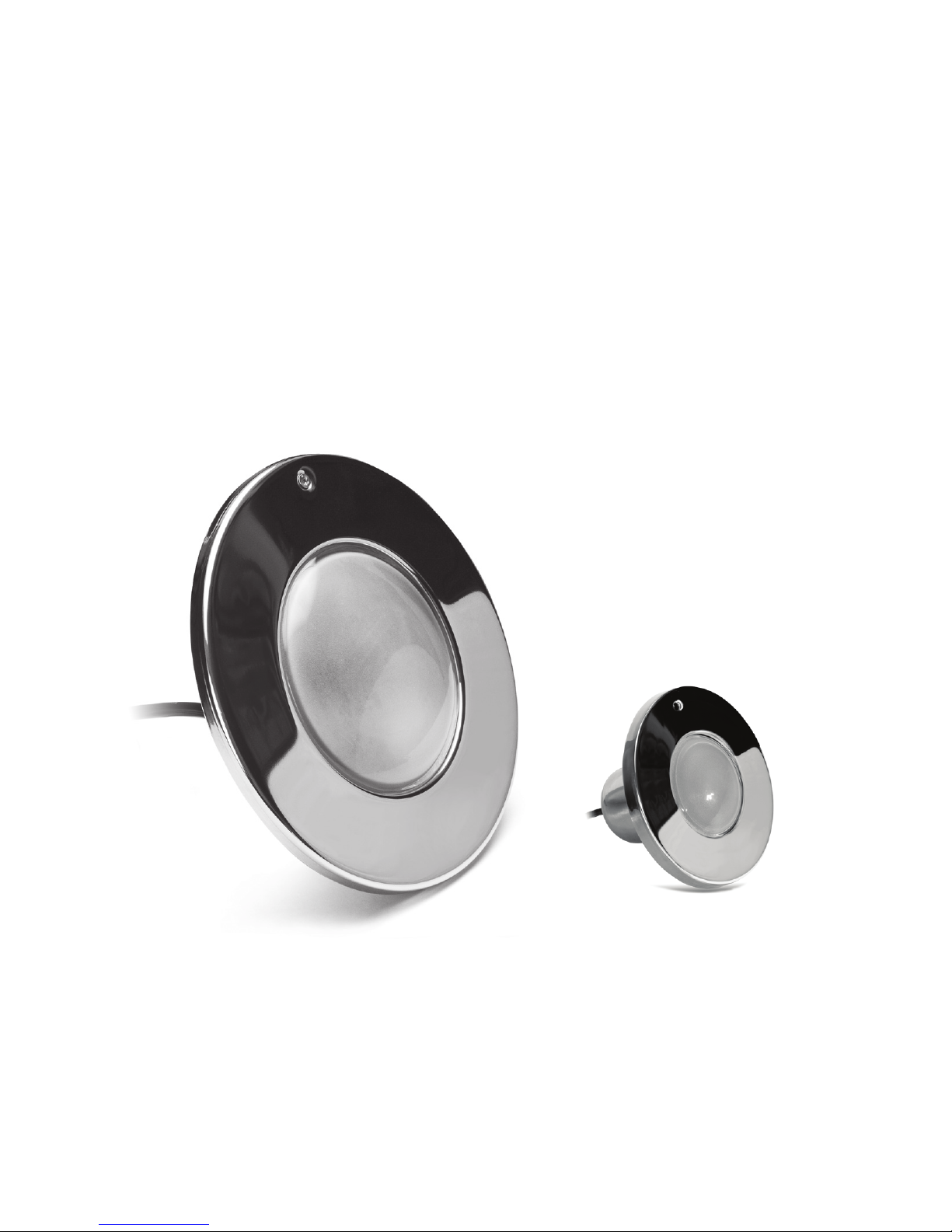
Color Splash® LED Pool and Spa
Light Fixture Installation and
Operation Guide
Color Splash® LED POOL AND SPA LIGHT FIXTURES
Available in 120VAC and 12VAC models
Color Splash LED Pool and Spa light xtures offer superior, color illumination for
your pool and spa. This owner’s manual contains important information on installing
and using your new Color Splash LED Pool and Spa light xture. Read and follow all
instructions contained in this manual. Please keep it in a safe place for future reference.
Most states and local codes regulate the construction, installation, and operation of
public pools and spas, and the construction of residential pools and spas. It is important
to comply with these codes, many of which directly regulate the installation and use
of this product. Consult your local building and health codes for more information.
Read and follow all warning notices and instructions contained in this guide before
installing or using the product. Severe injury, death or property damage may result if
the warnings and instructions contained in this manual are not followed.
INSTALLER NOTICE: This Installation and Operation Guide contains important
information about this LED light. Be sure to give this guide to the owner and/or
operator of the LED light for reference regarding the proper installation, operation
and use of this product.
DANGER! FAILURE TO PROPERLY INSTALL AND USE THIS PRODUCT CAN
RESULT IN SERIOUS BODILY INJURY OR DEATH.
WARNING! Comply with all related codes for the installation and
use of this product.
WARNING! Before installing or using this light, read all warnings and
instructions contained in this manual.
pg 1
COLOR SPLASH LED POOL AND SPA LIGHT FIXTURE NICHE COMPATIBILITY
For LPL-F1C ONLY
Pentair®: 78210400, 78210500,
78210600, 78210700, 79206700
Hayward®: SP0604C, SP0600U
Jandy®: PLNICLRG, SSNICLRG1R,
SSNICLRG1S
Jacuzzi®: 94131234
For LPL-S1C ONLY
Pentair®: 78244200, 78244300, 78243200,
78243300, 79206600
Hayward®: SP0606C, SP0610C
Jandy®: PLNICSM, SSNICSM1R, SSNICSM1S
Always disconnect power to the pool and/or spa light at the circuit breaker panel
before attempting to service the light. Failure to do so could result in serious injury
or death due to electrical shock. Installation must be performed in accordance with
all applicable federal, state & local installation codes and ordinances by a licensed or
certied electrician or a qualied pool professional. Improper installation may result
in death or serious injury to pool and/or spa users, installers or others due to electrical
shock. In addition, improper installation may cause property damage. This device is
not intended for use in anything other than in-ground pools/spas.
WARNING! Risk of electrical shock or electrocution
Do not, under any circumstances, splice wire underwater or behind the light niche
during the installation of this light.
Color Splash LED Pool and Spa light xtures are operated through the light’s switch.
No special controller or interface is required. Use a junction box to connect and
operate multiple lights with a single switch.
The following steps detail installation of the Color Splash LED light xture into a new
pool and/or spa construction. Read this section in its entirety prior to beginning any
installation.
WARNING! Important Safety Information for Light Installation
INSTALLER NOTICE: This light’s external cord cannot be replaced and should be
handled with care. Any damage to this external cord necessitates replacing the light.
pg 2
OPERATION FOR 120VAC AND 12VAC
COLOR SPLASH LED POOL AND SPA LIGHT FIXTURES
COLOR SPLASH LED POOL AND SPA LIGHT FIXTURES INSTALLATION
(NEW POOL AND/OR SPA CONSTRUCTION)
INSTALLER NOTICE: A licensed electrician must complete the following steps prior to
installation of this light in a new pool or spa construction.
RATED FIXTURE LIFE: The illumination generated by Color Splash LED light xtures
are based on Light Emitting Diode (LED) technology. The average expected xture
life is rated 50,000 elapsed time hours under normal operating conditions. Pool Water
Temp: 33°F to 97°F (1°C to 36°C), humidity: 0-95% non-condensing.

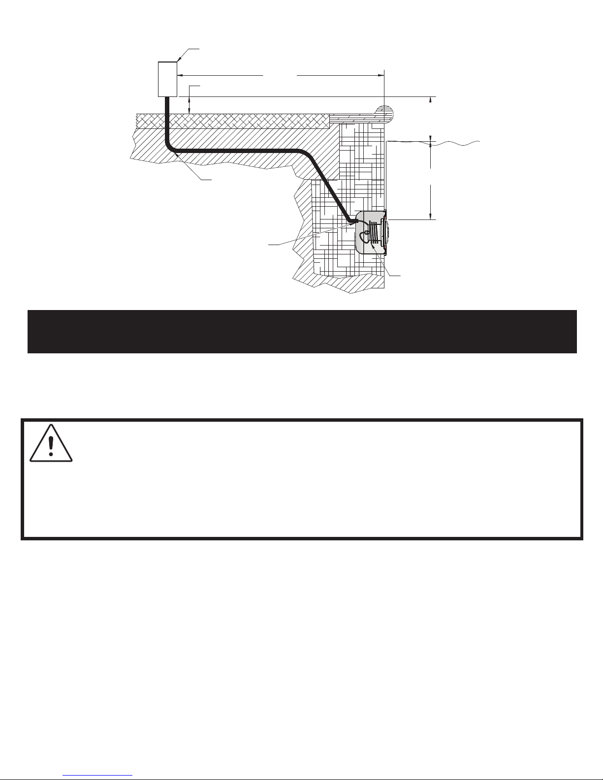
4" Min.
48" Min.
18" Min. Top of Lens
to Water Level
8" Min. Junction Box
or Low Voltage
Transformer to the
Max. Water Level of Pool
To: GFCI, Circuit Breaker,
and Power Source
Rigid Conduit
#8 AWG Ground
Connector Bonding
Lug is Located at
Rear of Niche
Coil 4 ft. of Power
Cord Around Fixture
Concrete Must Be Cut
Back Around Niche to
Allow for a Compacted
Plaster Seal
1. Feed the xture cord through the conduit to the junction box. Be sure to leave at
least four (4) feet of cord at base of the xture to coil around the light to ensure ease
of servicing once the pool and/or spa is lled; reference Figure 1.
Figure 1.
NEW CONSTRUCTION INSTALLATION STEPS
(ONCE ALL ELECTRICAL REQUIREMENTS ARE MET)
pg 3
ordinances. The electrical system must be installed by a licensed or certied electrician to
meet or exceed those requirements prior to installation of the light. This includes, but is not
limited to, the following National Electrical Code requirements:
• Installation of a ground fault circuit interrupter (GFCI) for line voltage models on the
lighting circuit with an appropriately rated circuit breaker.
• A junction box or low voltage transformer is located at least 8 inches above the maximum
pool water level and at least 48 inches from the pool edge; reference Figure 1.
• Proper electrical bonding of the light xture and all metal items within 5 feet of the pool
• Proper wet niche installation with the top edge of the underwater light’s lens at least
18 inches below the surface of the water in the pool and not more than 20” in Canada;
reference Figure 1.
• Proper electrical wet niche bonding and grounding using the #8 AWG ground connector
at the rear of the niche; reference Figure 1.
WARNING!
Conrm that the pool and/or spa meets all current National Electrical
Code (N.E.C.) Article 680-22 requirements and any applicable local codes or
2. At the junction box, cut the cord. Be sure to leave at least six (6) inches of cord for
making connections.
3. Carefully strip the outer cord jacket to expose six (6) inches of the underlying three
insulated wires.
4. Connect these three (3) wires to their corresponding junction box circuit wires and
secure the junction box cover in place.
damage to the light. If the light is operating without being fully submerged in water,
the light’s circuitry will automatically shut down for a cooling period before powering
back on within 10 minutes to prevent damage to the light.
WARNING! Do not operate this light for more than two minutes without
completely submerging it in water. Failure to do so can result in permanent
pg 4
This special pilot screw secures and electrically grounds the xture to the mounting
ring and wet niche. Failure to install the stainless steel pilot screw provided could
create an electrical shock hazard, resulting in death or serious injury to pool users,
installers or others.
5. Using the stainless steel pilot screw provided, install the Color Splash light assembly
into the niche, carefully tightening the pilot screw. (Reference Figure 1)
WARNING! Use only the stainless steel pilot screw provided with this
underwater light.
6. Fill the pool to completely submerge the light prior to operating the light. Do not
operate light out of water, this may cause damage to the light.
7. Make a nal check to conrm proper light operation by switching “on” the main
switch or circuit breaker and the light switch. The light should illuminate when
power is switched “on”. If the light is not operating, go back to Step 1 to recheck each
installation step for proper completion.
pg 5
Installation of this light must be completed by a licensed or certied electrician or a qualied
pool professional in accordance with the National Electrical Code and any applicable local
codes and ordinances. Improper installation may result in death or serious injury to pool
users, installers or others due to electrical shock. In addition, improper installation may
cause property damage.
Always disconnect power to the pool and/or spa light at the circuit breaker panel before
attempting to service the light. Failure to do so could result in serious injury or death due
to electrical shock.
Conrm that the pool or spa meets the current National Electrical Code requirements and
any applicable local codes or ordinances. The electrical system must be installed by a
licensed or certied electrician to meet or exceed those requirements prior to installation
of the light. This includes, but is not limited to, the following National Electrical Code
requirements:
• Installation of a ground fault circuit interrupter (GFCI) for line voltage models on the
lighting circuit with an appropriately rated circuit breaker.
• A junction box or low voltage transformer is located at least 8 inches above the maximum
pool water level and at least 48 inches from the pool edge; reference Figure 1.
• Proper electrical bonding of the light xture and all metal items within 5 feet
of the pool and/or spa.
• Proper wet niche installation with the top edge of the underwater light’s lens at least
18 inches below the surface of the water in the pool and not more than 20” in Canada;
reference Figure 1.
• Proper electrical wet niche bonding and grounding using the #8 AWG ground connector
at the rear of the niche; reference Figure 1.
• The wet niche is properly electrically bonded and grounded via the No. 8 AWG ground
connector located at the rear of the niche; see Figure 1.
COLOR SPLASH LED POOL AND SPA LIGHT FIXTURE INSTALLATION
(EXISTING POOL AND/OR SPA)
Danger - Risk of electrical shock or electrocution!
The following steps detail installation of the Color Splash LED light xture into an
existing pool. Read this section in its entirety prior to beginning any installation.
1. Disconnect the main electrical switch or circuit breaker and the switch which
operates the installed light.
2. Remove the existing light per the original manufacturer’s instructions. Place the
light xture on the deck.
3. Leaving the light xture on the deck, cut the light cord. Be sure to leave at least
six (6) inches of cord in order to connect it to the replacement light cord. Discard the
light xture.
4. Remove the existing cord by pulling it up out of the niche and onto the deck.
Failure to bring the pool and/or spa electrical system up to current code requirements
prior to light installation may create an electrical shock hazard resulting in death or
serious injury to users, installers, or others due to electrical shock, and may also cause
property damage.
WARNING! Pool or spa electrical system must meeting current
code requirements.
4" Min.
48" Min.
18" Min. Top of Lens
to Water Level
8" Min. Junction Box
or Low Voltage
Transformer to the
Max. Water Level of Pool
To: GFCI, Circuit Breaker,
and Power Source
Rigid Conduit
#8 AWG Ground
Connector Bonding
Lug is Located at
Rear of Niche
Coil 4 ft. of Power
Cord Around Fixture
Concrete Must Be Cut
Back Around Niche to
Allow for a Compacted
Plaster Seal
Figure 1.
EXISTING CONSTRUCTION INSTALLATION STEPS
(ONCE ALL ELECTRICAL REQUIREMENTS ARE MET)
pg 6

pg 7
Carefully strip the outer cord jacket to expose six (6) inches of the underlying three
insulated wires.
5. Tape the three existing light wires to the replacement light cord with electrical
insulating tape. Avoid wrapping too much tape around the cords. Otherwise, the
thickness will be too great for the cord to be able to be pulled through the conduit
to the junction box.
6. After removing the junction box cover, disconnect the light xture wires. Then, pull
the cord through the conduit until it is visible in the junction box conduit. Remove the
tape from the cords and separate the wires.
7. Carefully strip the outer cord jacket from the new light cord to expose six (6) inches
of the underlying three insulated wires.
8. Connect these three (3) wires to their corresponding junction box circuit wires and
secure the junction box cover in place.
9. Be sure to leave at least four (4) feet of cord at base of the xture to coil around the
light to ensure ease of servicing; reference Figure 1.
10. Install the Color Splash LED light xture into the niche.
11. Using the stainless steel pilot screw provided, install the Color Splash LED light
xture assembly into the niche, carefully tightening the pilot screw. (Reference Figure
1)
12. Make a nal check to conrm proper light operation by switching “on” the main
switch or circuit breaker and the light switch. The light should illuminate when
power is switched “on”. If the light is not operating, go back to Step 1 to recheck each
installation step for proper completion.
INSTALLER NOTICE: This light’s external cord cannot be replaced and should be
handled with care. Any damage to this external cord necessitates replacing the light.
This special pilot screw secures and electrically grounds the xture to the mounting
ring and wet niche. Failure to install the stainless steel pilot screw provided could
create an electrical shock hazard, resulting in death or serious injury to pool users,
installers or others.
WARNING! Use only the stainless steel screw provided with this underwater
light.

Color Splash LED light xtures are pre-programmed and synchronous with each other
while offering a wide array of lighting effects and options. They offer ve different
light shows to choose from, as well as a Color Lock feature which allows you to “lock”
the light on any solid color.
Color Splash LED light xture features are selectable by turning the existing pool
light switch off and on, known as power cycling. The amount of time the light is off
during the power cycling determines the light feature activated.
1. Parisian Blue
2. Brazilian Red
3. Tahitian Blue
4. Miami Pink
5. Tuscan Orange
6. Arctic White
7. New Zealand Green
1. Northern Lights
2. Super Nova
3. Desert Bloom
4. Patriot Dream
5. Tidal Wash
SOLID COLORS
Your Color Splash LED light xture has seven colors available for you to experience.
Available colors are:
LIGHT SHOWS
Your Color Splash LED light xture has ve light shows from which you can choose.
The rst three light shows display all seven solid colors, while the last two display
selected colors.
SELECT SOLID COLORS
You can select a solid color at anytime by activating the “Color Lock” feature. The Color
Lock feature allows you to stop a light show and “lock” Color Splash on a solid color.
CHANGE LIGHT SHOW
Changing light shows: Turn the pool light power off for 3 seconds and then back on
again. Color Splash LED light xture will advance from the show that is was previously
on, to the next show. Repeat the “change light shows” procedure until the desired light
show is reached.
LIGHTING OPERATION:
CHOOSING COLORS AND LIGHT SHOWS
LIGHTING OPERATION:
HOW TO CHANGE LIGHT SHOW AND SELECT SOLID COLORS
pg 8

pg 9
DEACTIVATION THE COLOR LOCK FEATURE
Turn the pool light power off and then back on again within 2 seconds. Color Splash
will resume light show.
MEMORY MODE
When your Color Splash LED light xtures are turned off for more than 10 seconds,
the solid color or light show on display will be stored. The next time the power is
turned on, the xture will resume displaying that same color or light show.
RESET/SYNCHRONIZE MODE
To activate the reset mode, turn the power off and back on again within 1 second,
three times in a row (off/on, off/on, off/on). All the xtures connected to the switch
will indicate they have been reset and synchronized by ashing red four times. When
you rest the Color Splash LED light xtures they will go back to the Northern Lights
light show.
1. NORTHERN LIGHTS (FACTORY DEFAULT LIGHT SHOW)
Show: Slow cross-fade through all seven solid colors.
Cycle: Two minute color sequence cycle with slow cross-fade between colors. Fixture
will hold on each solid color for 8 seconds before moving to the next.
2. SUPER NOVA
Show: Quick and random ashes through all seven solid colors.
Cycle: Random fast change between solid colors in half second intervals.
NOTE: Your Color Splash LED light xtures are “synchronous”, meaning you can experience
the same light shows in your pool and spa at the same time. However, all of the pool lights
must be on the same electrical circuit for this feature to be operational. Please consult a
qualied electrician to determine your specic pool and spa circuit conguration.
DESCRIPTION OF LIGHT SHOWS AND SOLID COLORS
ACTIVATING THE COLOR LOCK FEATURE
Turn the pool light power off and then back again in 2 seconds. Color Splash will
“lock” on the color it was displaying at the time when you turned it off.
pg 10
5. TIDAL WAVE
Show: Slow cross-fade between green and blue.
Cycle: 24 second cycle through green and blue with slow cross-fade between solid
colors.
(TIP: The Northern Lights show is the best show to use in order to practice using the Color
Lock feature of the xture.)
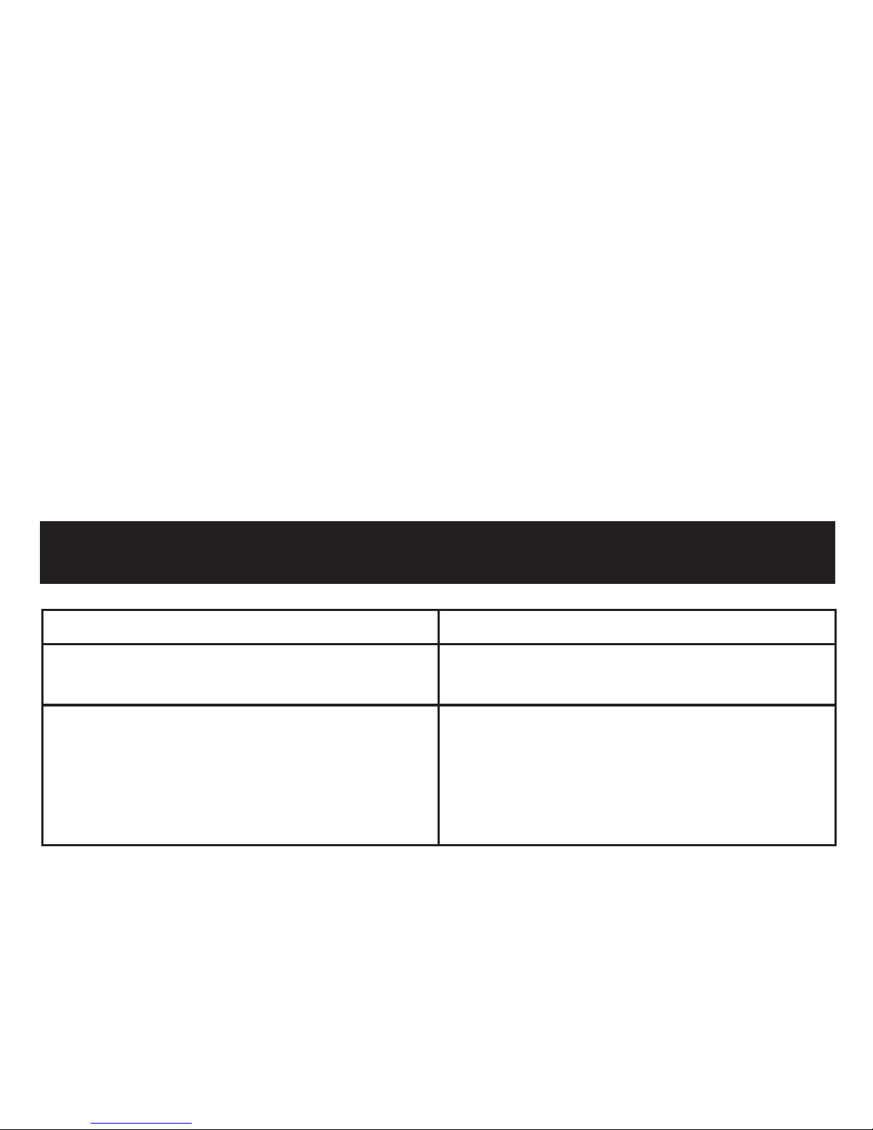
PROBLEM REASON/CAUSE
The light xture will not illuminate Check the GCFI ground fault wiring and
reset if necessary
Light xture does not function properly Check the xture wiring connection to
the junction box at the pool side and
the AC power swtich.
Be sure that there is proper AC power
applied to the xture.
TROUBLESHOOTING
4. PATRIOT DREAM
Show: Quick cross-fade through red, white and blue only.
Cycle: 11 second cycle through red, white and blue with quick cross-fade between
colors. Fixture will stay on each solid color for 3 seconds before moving to the next..
3. DESERT BLOOM
Show: Very slow cross-fade through all seven solid colors.
Cycle: Seventy-seven minute color sequence cycle with super slow cross-fade between
solid colors. Fixture will stay on each solid color for 10 minutes before moving to the
next.

© 2013 J&J Electronics, Inc. All rights reserved. Color Splash® is a trademark of and manufactured by J&J Electronics, Inc. All registered and trademarked brands and names are
the property of their respective companies. REF. 051513
J&J Electronics | Irvine, California
www.jandjpoolspa.com
J&J ELECTRONICS, INC. 3-YEAR LIMITED WARRANTY
COLOR SPLASH® and PUREWHITE
TM
LED LIGHT FIXTURES
J&J Electronics, Inc. (“J&J”) warrants its LED In-Ground Light Fixtures to be free from defects in material and workmanship, under normal
use, conditions and service, from the date of purchase and warrants its products as follows:
Product Line Structural Housing LED Module
Pool/Large Fixture Three (3) Year Three (3) Year*
Spa/Small Fixture Three (3) Year Two (2) Year*
*If during the rst twenty-four (24) months (Pool/Large Fixture) and rst twelve (12) months (Spa/Small Fixture) of the warranty period,
the LED Module fails to operate due to a defect in material or workmanship, J&J will, at its option, repair or replace xture at no charge. If
during months twenty-ve (25) through thirty-six (36) (Pool/Large Fixture) and months thirteen (13) through twenty-four (24) (Spa/Small
Fixture), the LED Module fails to operate due to a defect in material or workmanship, J&J will grant the purchaser a pro-rated credit for
purchase of a J&J LED Light Fixture, as the purchaser’s sole remedy.
TERMS AND CONDITIONS
This warranty is available to the original purchaser of the product(s) only. This warranty applies only when products are properly installed
in an in-ground pool/spa; any other use voids the warranty. Products must be used in lighting equipment designed and approved for the
application and in environmental conditions within the normal specied operating range. This warranty does not apply to any abnormal
use of product(s), use in violation of any applicable standard, code or instructions for use in installations including those contained in the
latest National Electrical Code (NEC), the Standards for Safety of Underwriters Laboratory, Inc. (UL), Standards for the American National
Standards Institute (ANSI). This warranty will not apply in the event of conditions demonstrating abnormal use or stress, under/over
voltage/current conditions, excessive switching cycles or operating hours or outside the recommended operating conditions. This warranty
does not apply to color shifts or dimming caused by emissions. LED color shifts and dimming occur normally over time. This warranty does
not cover damage occurring during shipment, damage or failure resulting from alteration, accident, acts of God, theft, abuse, negligent
installation, improper service, unauthorized repairs, freezing or where adequate care has not been taken to prevent damage to the
product(s). Tampering with any internal component of this product(s) will void the warranty.
This warranty gives you specic rights. You may have other rights that vary according to the laws of your state.
LIMITATION OF LIABILITY
THE FOREGOING SHALL CONSTITUTE THE EXCLUSIVE REMEDY OF THE PURCHASER AND IS IN LIEU OF ALL OTHER WARRANTIES,
WHETHER EXPRESS OR IMPLIED, INCLUDING ALL WARRANTIES OF MERCHANTABILITY OR FITNESS FOR A PARTICULAR PURPOSE, AND
ALL WARRANTIES ARISING FROM COURSE OF DEALING OR USAGE OR TRADE. THE LIABILITY OF J&J UNDER THIS WARRANTY SHALL
BE LIMITED TO THE REPLACEMENT, REPAIR OR PRO-RATED CREDIT OF THE PRODUCT(S) AS STATED HEREIN. J&J IS NOT RESPONSIBLE
FOR SHIPPING OR TRANSPORTATION COSTS RELATED TO OBTAINING WARRANTY SERVICE. IN NO EVENT SHALL J&J BE LIABLE FOR
ANY OTHER COSTS OR DAMAGES, INCLUDING LOST PROFITS OR REVENUES, LABOR CHARGES OR FOR ANY INCIDENTAL, SPECIAL OR
CONSEQUENTIAL DAMAGES.
J&J reserves the right to change the warranty, warranty period without prior notice and without incurring obligation.
To obtain warranty service, retain the failed Product; retain the installation invoice showing product purchase price and contact J&J
Electronics, Inc. at 800.735.4553 ext. 242 or warranty@jandjelectronics.com. As of 05/14/2013
 Loading...