

Page 1

1
K3-A
USER MANUAL
Ver.1.0.6
Last updated:2017/07/24
Thank you for choosing K3-A flight controller. Hope you will have a good
flight with K3-A. We strongly recommend you to read this manual
carefully before you install K3-A flight controller. The following
instructions will help you to make your K3-A flight controller work
perfectly.
Note: This manual shall be used together with the K3-A assistant
software. If you find differences between this manual and the assistant
software, please follow the assistant software.
If you have any difficulty during the usage, please contact with JIYI
Robotic Co., Ltd. at [email protected]
JIYI Robotics CO. Ltd
Page 2

2
Content
1. Technical Terms and Abbreviations ............................................................................... 5
2. Packing List .............................................................................................................................. 5
3. Setup Wizard ........................................................................................................................... 6
3.1 Aircraft Types ............................................................................................................... 6
3.2 Wiring Diagram ........................................................................................................... 6
3.3 FCU Setup ...................................................................................................................... 8
3.4 GPS Setup ...................................................................................................................... 8
4. Configuring by Assistant Software ............................................................................... 10
4.1 Installing driver and Assistant Software .......................................................... 10
4.2 Connect to the FCU .................................................................................................. 11
4.3 The configuration FCU ............................................................................................ 12
5. Fligth ........................................................................................................................................ 13
5.1 Flight mode introduction ....................................................................................... 13
5.2 Advanced Fountion .................................................................................................. 13
5.3 Introduction to the Functions of Remote Controller ......................................... 23
Appendix: ................................................................................................................................. 28
Appendix1 Product Specification: ........................................................................... 28
Appendix2:LES STATUS DESCRIPTION ..................................................................... 30
Appendix3 :JIYI Technical Suppport .......................................................................... 31
JIYI Robotics CO. Ltd
Page 3

3
Disclaimer
Kindly Reminder: K3-A is not a toy, please read the manual carefully before you use
this product. Upon reading this, you’re deemed to agree with the disclaimer, this
products is not suitable for people aged below 18 years old.
This product is a professional flight controller developed by JIYI for industrial
application. Under the normal electric supply and instant condition, this controller
can satisfy plant protection, mapping, Aerial photography and other purposes . JIYI
is always aiming high quality, reliable and stable products. As safety consideration,
we strongly recommend you to remove the propeller during the configuration,
ensure the wiring connection and electric supply are in place, and stay away from
crowd, fragile and dangerous objects during the flight. If any of below reason (not
limited to below reason) occur during the use of our products, JIYI shall not be
liable for any direct or indirect loss, damages and injuries that result from the usage
of our products. JIYI shall only be responsible for flight controller damaged which is
caused by the controller itself. JIYI shall not be liable for any other form of Liability
and Compensation.
1.User do not follow the manual during the usage;
2.Weak structure of aircraft or damage on aircraft structure;
3.User using third party product which caused the abnormal flight;
4.User’s wrong judgment or improper handling;
5.User intended to against others;
JIYI Robotics CO. Ltd
Page 4

4
6.User continue with the flight even though knew that the product is function
abnormally;
7.Flying under the condition of strong interference, radio interference and
prohibited area or vision unclear or blocked or unable to judge and identify the
flight condition;
8.Under bad weather condition or not suitable flight condition;
9.Abnormal working condition of flight controller where caused by user tearing or
modifying the JIYI product and accessories;
10.Flight where user under drunk, drug abuse or any other unhealthy condition;
11.Any others products defects which is not caused by JIYI products.
JIYI Robotics CO. Ltd
Page 5
5
CH
Channel
FS
Fail Safe Protection
FCU
Flight Controller Unit
PMM
Power Management Module
ESC
Electronic speed controller
JIYI
JIYI Robotics CO.,Ltd.
1. Technical Terms and Abbreviations
2. Packing List
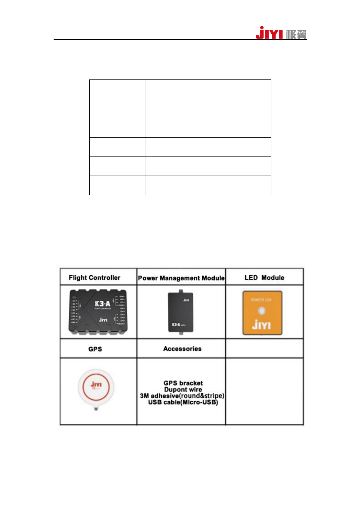
Standard Packing:FCU1, PMM 1, GPS/Magnetic Compass Module 2, GPS
Folding bracket 2, LED Module 1, Dupont cables 8, Micro-USB cable1,
3M MoveDots(ROUND)2, 3M MoveDots (STRIPE)2
The Optional Module : Flow Sensor 1; Radar Module 1;
Bluetooth Datalink 1 ;RTK Module1;
JIYI Robotics CO. Ltd
Page 6
6
3. Setup Wizard
3.1 Aircraft Types
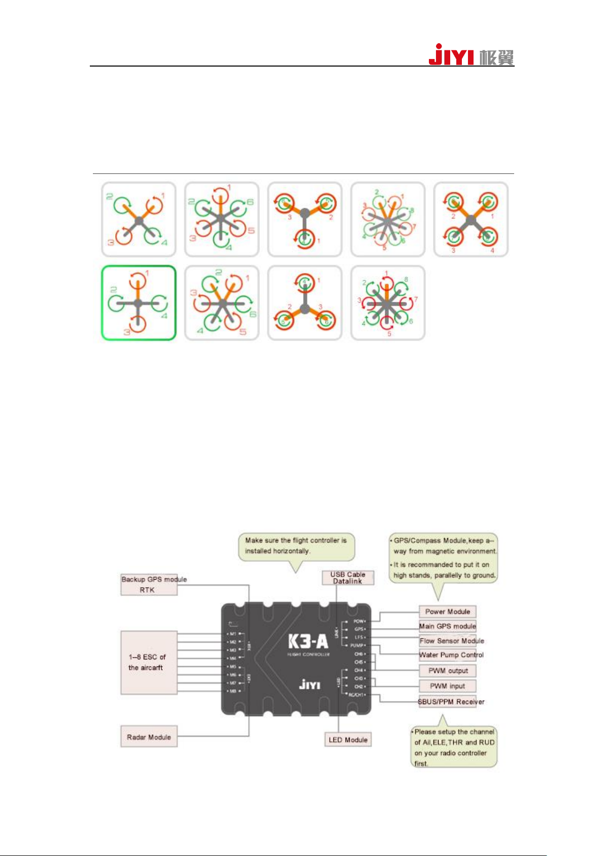
Supported Aircraft Types are showing in the following figures:
Notes :
(1) It uses the yellow arms to show the nose direction;
(2) Those marked numbers matches the input ports M1 to M8 of FCU;
(3) The upper propellers of coaxial multicopter indicates by green and the lower
indicates by red.
3.2 Wiring Diagram
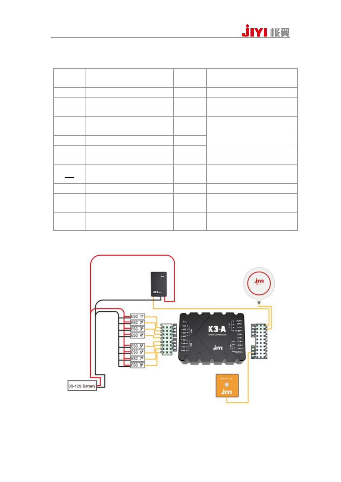
3.2.1 Instruction of Ports
JIYI Robotics CO. Ltd
Page 7
7
The port definitions of K3A is showing in the following table:
M1
Connects to ESC 1 #
POW
Connects to power management
module
M2
Connects to ESC 2 #
GPS
Connects to GPS module
M3
Connects to ESC 3 #
LFS
Connects to flow sensor
M4
Connects to ESC 4 #
PUMP
Communicates to water pump
M5
Connects to ESC 5 #
CH6
Communicates to the second
water pump
M6
Connects to ESC 6 #
CH5
PWM output, controlled by OUT2
M7
Connects to ESC 7 #
CH4
PWM output, controlled by OUT1
M8
Connects to ESC 8 #
CH3
Connects to switchlevel meter
RTK
Connects to GPS2 module or RTK
module
CH2
Connects to percentage level
meter
EXT
Connects to radar module
RC/CH1
Connects to PPM/SBUS receiver
LINK
Use USB to connects to Assistant2
or use datalink to connect to APP
LED
Connects to LED tricolored light
module
2、Overall Wiring Diagram
JIYI Robotics CO. Ltd
Page 8
8
3.3 FCU Setup
3.3.1 The Direction of K3A FCU
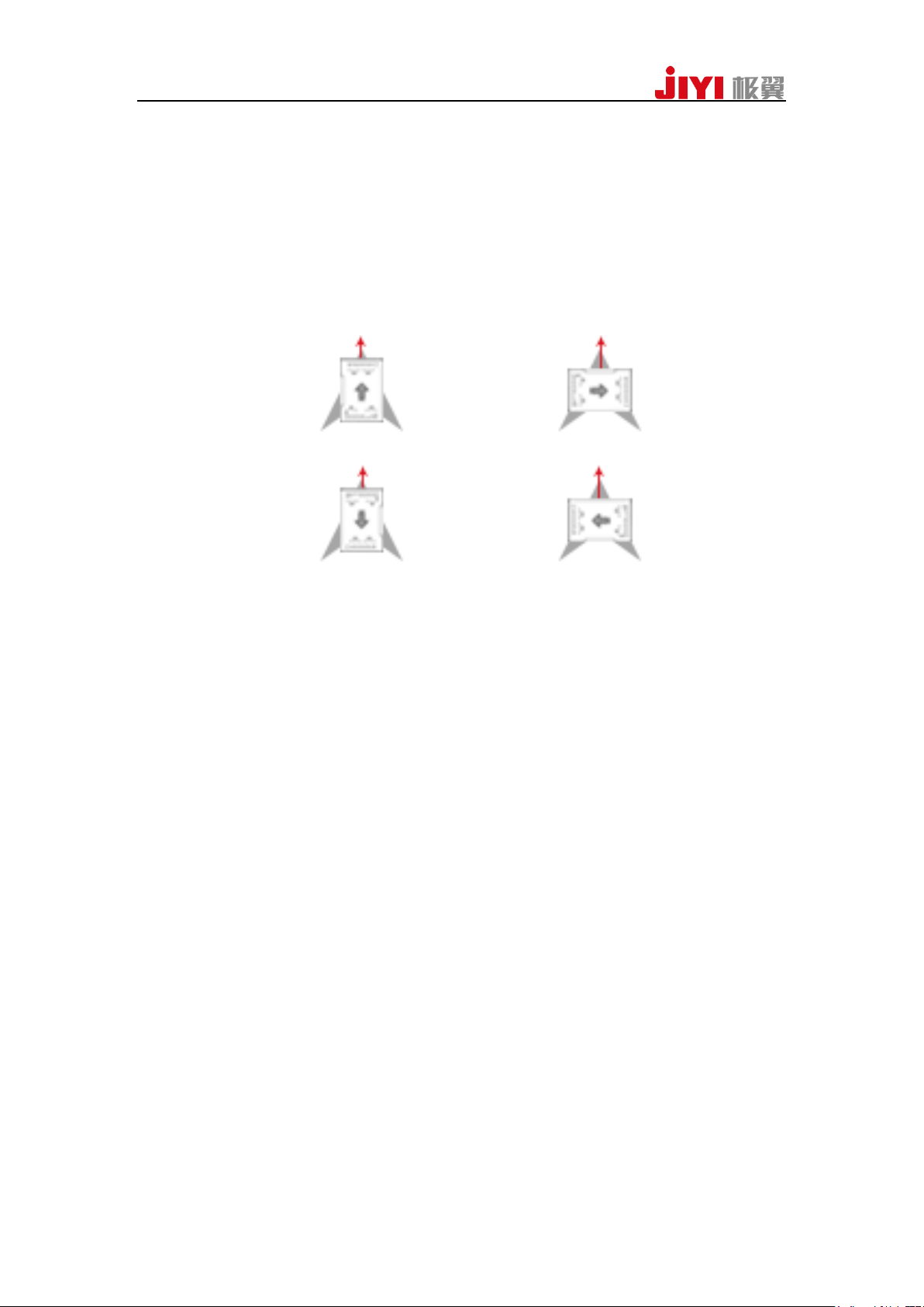
Please choose a direction as the following figure shown. And set the
corresponding configuration in the Assistant2 Software.
PATH: Basic Setting ->Installation - > IMU Direction. ( Nose direction indicates
by the red arrow).
3.3.2 Installation Position
(1) The K3A FCU must be face-up. Please don’t invert it and try your best to keep
paralleled .
(2) In order to guarantee the best flight effect, we suggest to install FCU horizontally
in the gravity center of the aircraft.
(3) The internal vibration reduction system has been assembled in FCU, so please use
tough 3M movedots to fix the FCU.
3.4 GPS Setup
3.4.1 Install Direction
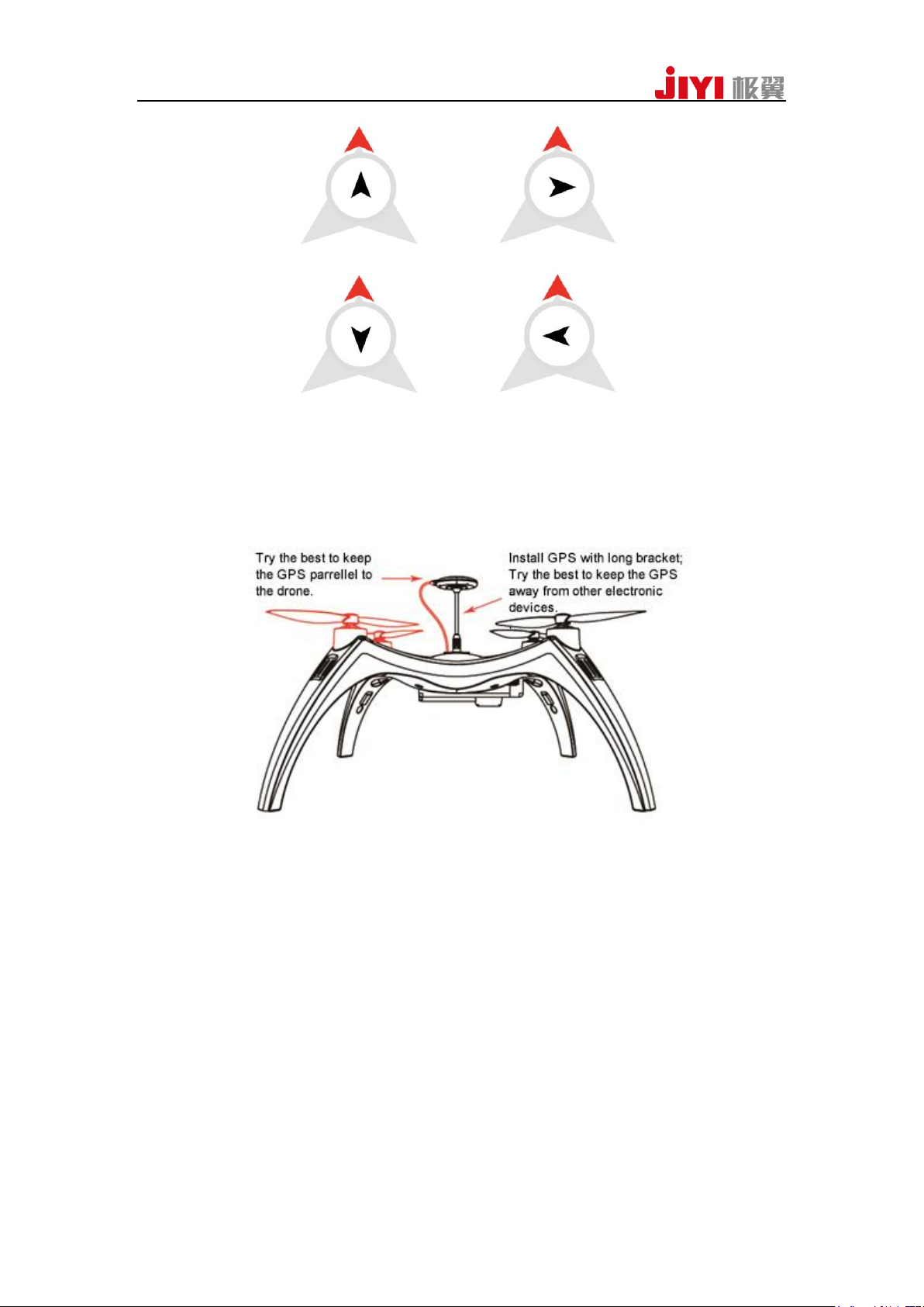
Please choose a direction as the following figure shown.And set the
corresponding configuration in the Assistant2 Software.
PATH:Basic Setting ->Installation - >GPS direction . ( Red arrow indicates the
nose direction).
JIYI Robotics CO. Ltd
Page 9
9
3.4.2 Installation Position
(1) GPS module should be installed as high as possible. And keep it far away from
ESC, power wires, motors and battery;
(2) Ensure to fly in open environment (no shield);
(3) Avoid flying under magnetic interference;
(4) Please don’t put magnetic stuff close to the GPS, otherwise it could be cause to
permanent damage of the compass.
JIYI Robotics CO. Ltd
Page 10
10
4. Configuring by Assistant Software
4.1 Installing driver and Assistant Software
1、Boot up the computer, and then visit JIYI’s official website (www.jiyiuav.com).
Download the driver program and K3A Assistant2 software;
2、Run the installation program of the driver and the assistant software installation
program;
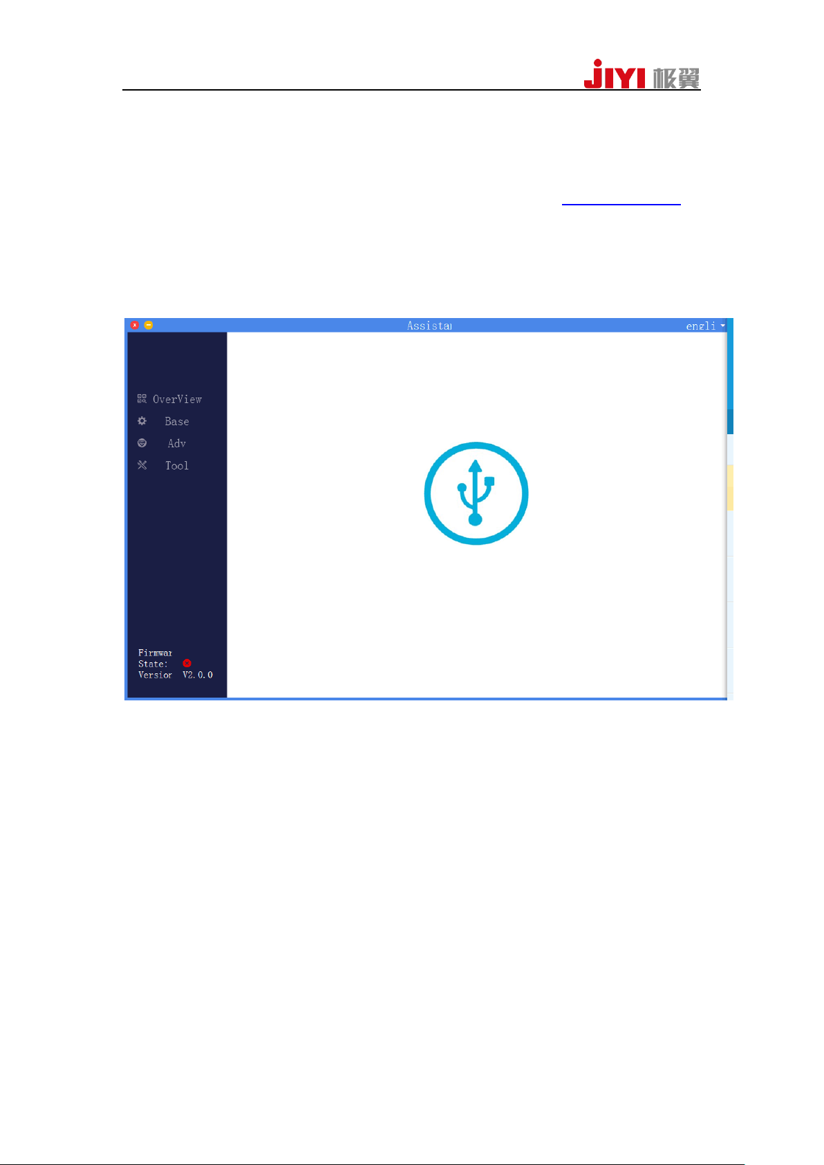
3、After the installation is completed, open the assistant software. The interface is
shown as below:
JIYI Robotics CO. Ltd
Page 11
11
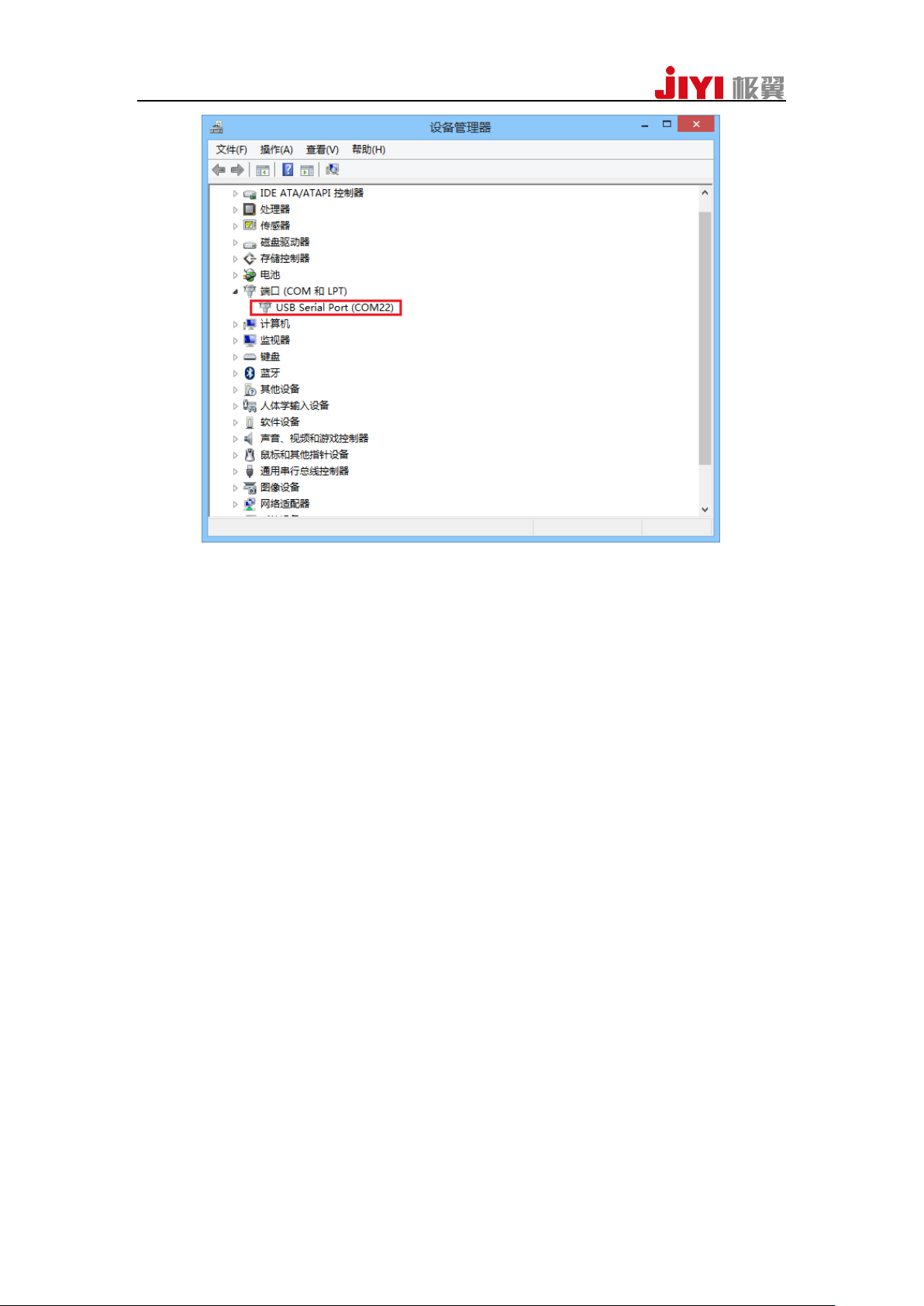
Attention: USB port of computer just can supply 0.5A current at most for flight
controller. If there are excessive peripherals mounted on flight controller, it
would lead to insufficient power supply and connection failure, and at this
moment it needs power supply. The propeller must be discharged when you use
power supply, meanwhile the motor should be turned off.
4.2 Connect to the FCU
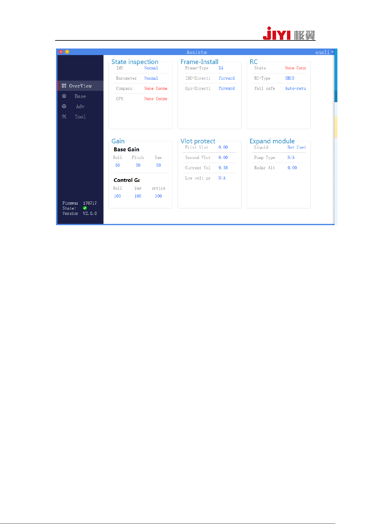
Click the “Connect” button , the following interface shows the FCU had beed
connected successfully.
JIYI Robotics CO. Ltd
Page 12
12
4.3 The configuration FCU
Please read < ASSISTANT2>
JIYI Robotics CO. Ltd
Page 13
13
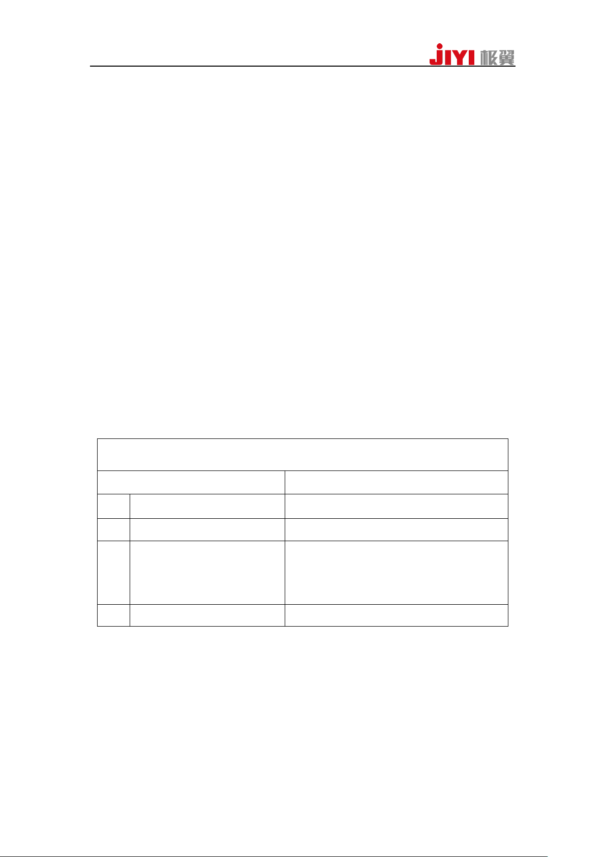
ATT-STA
Channel setting
Description
CH1
Control roll angle
To change the desire roll angle of aircraft
CH2
Control pitch angle
To change the desire pitch angle of aircraft
CH3
Control throttle value
Different from ATT-ALT mode, flight
controller doesn’t involve in altitude
control. the hover-throttle value will be
changed with the driver system of aircraft.
CH4
Control the rate of yaw
To change the desire rate of pitch angle
5. Flight
5.1 Flight mode introduction
5.1.1 ATT-STA
ATT-STA is the basic mode of all flight mode ,which only depends on the
IMU .And it couldn’t be influenced by other sensors. It’s the most stable and safest
flight mode.
1、Working condition
The ATT-STA mode can be switched in any status. And it also supports arm and
disarm the FCU. If the aircraft is in the mode, LED will be flashed single green.
2、Operation description
Switch CH5 of the remote controller to the ATT-STA mode. Arm FCU and push
the throttle until the aircraft taking off. The taking-off throttle depends on the driver
system of the aircraft. Because of the advanced algorithm of flight controller, you can
easily make aircraft hover without controlling the throttle lever under indoors or
breezeless environment.
To find the respective function of the stick, please refer to the following table:
5.1.2 ATT-ALT
ATT-ALT mode is suitable for central-control remote controller. In the mode,
IMU and Barometer will both involve in flight control.
JIYI Robotics CO. Ltd
Page 14
14
1、Working condition
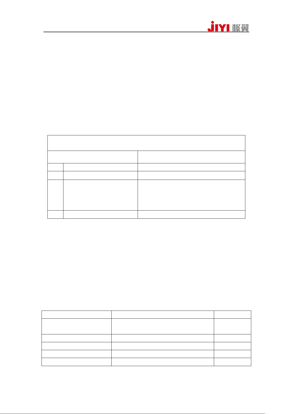
ATT-ALT
Channel setting
Description
CH1
Control roll angle
To change the desire roll angle of aircraft
CH2
Control pitch angle
To change the desire pitch angle of aircraft
CH3
Control speed of altitude
Different from ATT-STA mode, flight
controller would involve in altitude
control. When the throttle is in the middle,
the aircraft stays in constant altitude.
CH4
Control the rate of yaw
To change the desire rate of pitch angle
GPS Status
Indicator Light Status
Priority
Unconnected GPS/GPS no
receives satellite
Red indicator blinks for three times
Low
Bad signal
Red indicator blinks twice
low
Normal signal
Red indicator blinks once
low
Good signal
Red indicator doesn’t blink
low
RTK positioning
Yellow indicator blinks once
The ATT-ALT mode can be switched in any status. And it also supports arm and
disarm the FCU. If the aircraft is in the mode, LED will be flashed single green.
2、Operation description
Switch CH5 of the remote controller to the ATT-ALT mode. Arm FCU and push
the throttle. If throttle stick under 50%, motors will be idling. And you can push the
throttle stick gently to make the aircraft take off. If the throttle is placed in 50%
position, the aircraft will be in alt-hold flight .
To find the respective function of the stick, please refer to the following table:
5.1.3 GPS-ANGLE
GPS-ANGLE mode is the most commonly flight mode, and it can meet with most
demands of customers on flight control. In the mode, Besides IMU and Barometer,
compass and GPS also involve in flight control.
1、Working condition
Owning to use GPS to control the aircraft, so it has to wait for the complete of
searching satellite and achieve to the required positioning precision. You can arm the
aircraft, when GPS status in normal ,good or RTK positioning. The following table
shows different LED status with different GPS status.
JIYI Robotics CO. Ltd
Page 15
15
If the aircraft is in the mode, LED will be flashed green twice.
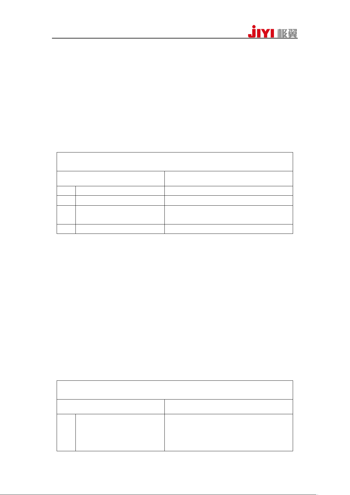
GPS-ANGLE
Channel setting
Description
CH1
Control roll angle
To change the desire roll angle of aircraft
CH2
Control pitch angle
To change the desire pitch angle of aircraft
CH3
Control speed of altitude
When the throttle is in the middle, the
aircraft stays in constant altitude.
CH4
Control the rate of yaw
To change the desire rate of pitch angle
GPS-ANGLE
Channel setting
Description
CH1
Control the rate of
roll angle
Different from GPS-angle mode, the stick
couldn’t control the roll angle of the
aircraft any more, but strictly controls the
flight speed of the aircraft in roll direction.
2、Operation description
After searching satellite or RTK positioning, switch CH5 of the remote controller
to the ATT-ALT mode. Arm FCU and push the throttle. If throttle stick under 50%,
motors will be idling. And you can push the throttle stick gently to make the aircraft
take off. If the throttle is placed in 50% position, the aircraft will be in alt-hold
flight .If the aircraft is in motion, all the control sticks of remote controller return to
the middle position, the aircraft will brake and hover automatically.
To find the respective function of the stick, please refer to the following table:
5.1.4 GPS-SPEED
GPS-speed mode is the strictest flight mode to control the flight speed of aircraft,
It can meet with the demands of the speed-sensitive users. In the mode, Besides IMU
and Barometer, compass and GPS also involve in flight control.
1、Working condition
The working condition is as same as GPS-angle mode.
2、Operation description
The description of control stick is different from GPS–ANGLE mode, other
operations are as the same as GPS-angle mode.
To find the respective function of the stick, please refer to the following table:
JIYI Robotics CO. Ltd
Page 16
16
CH2
Control the pitch of
roll angle
Different from GPS-angle mode, the stick
couldn’t control the pitch angle of the
aircraft any more, but strictly controls the
flight speed of the aircraft in pitch
direction.
CH3
Control speed of altitude
When the throttle is in the middle, the
aircraft stays in constant altitude.
CH4
Control the rate of yaw
To change the desire rate of pitch angle
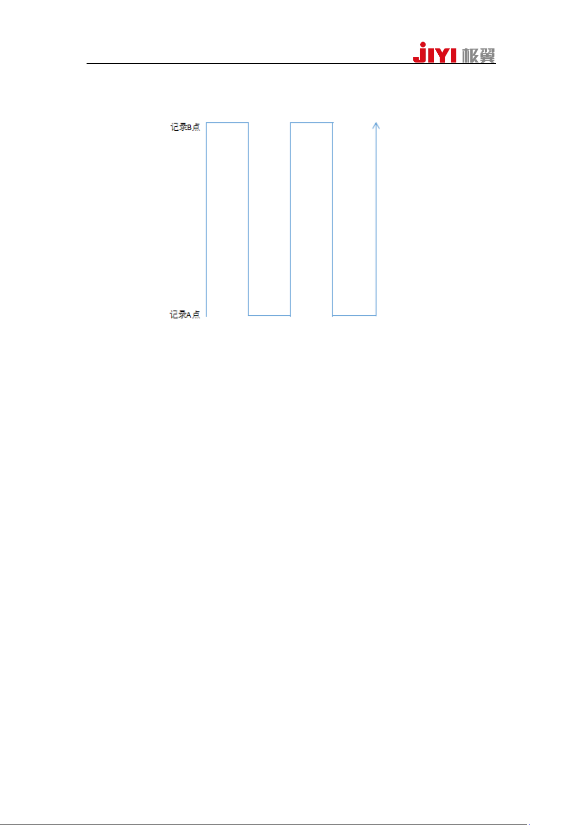
Gear 1: close
Gear 2: record A
Gear 3: record B
AB record
channel value
p<=1200
1400<=p<=1600
p>=1800
5.1.5 AB-MODE
1、Setting
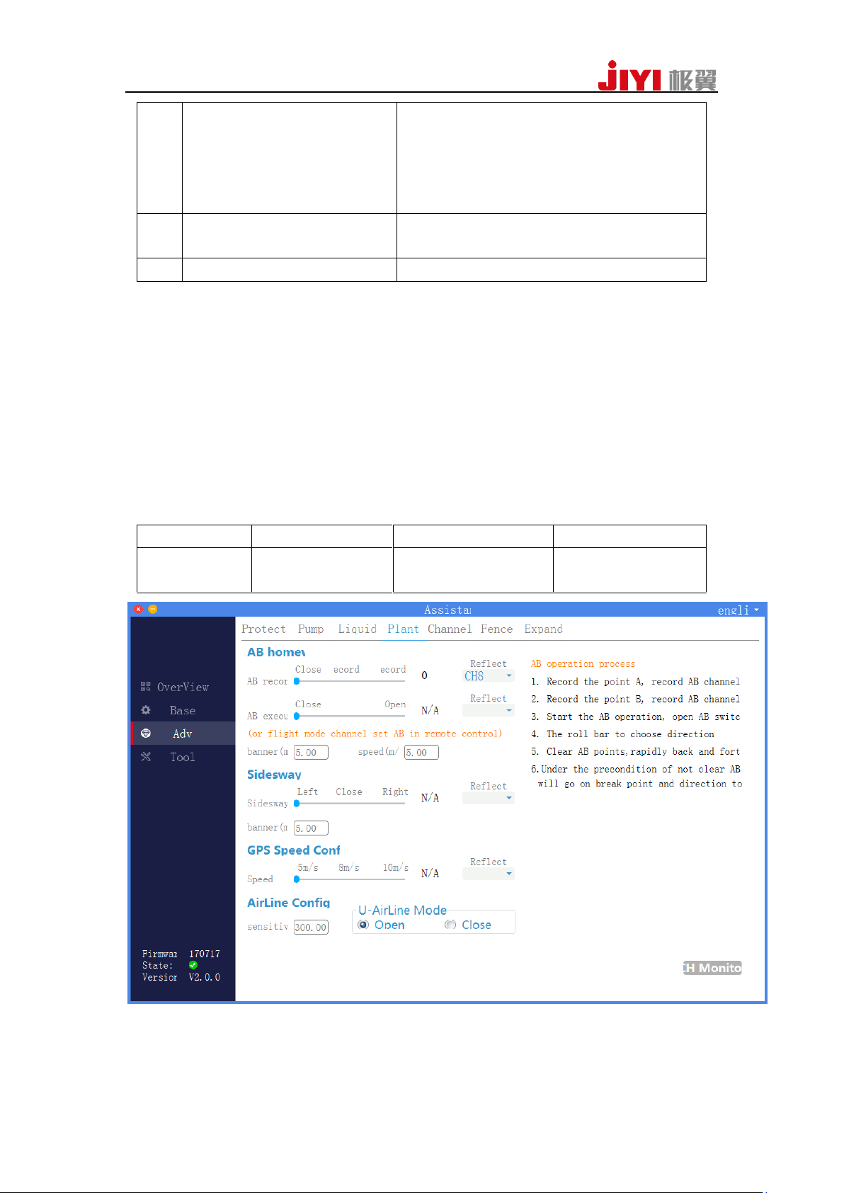
Before using the mode, you need connect to the Assistant2 Software for some
channel setting.
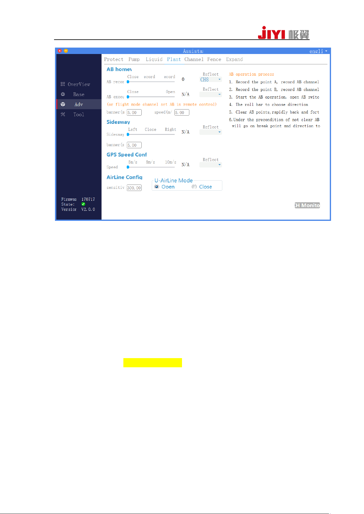
Settings of AB record: connect to Assistant2 Software and enter the path of
“Adv”—“Plant”. Read AB operation process.
JIYI Robotics CO. Ltd
Page 17
17
2、Operation description
Step 1: Record A waypoint:
Hovering in GPS mode, switch the control stick of AB record to Gear 2. If
recording has finished, LED will flash yellow light for 2 seconds.
Step 2: Record B waypoint:
Making the aircraft to fly to the wanted place and hovering the aircraft .Switch
the control stick of AB record to Gear 3. If recording has finished, LED will flash
green light for 2 seconds.
Step 3: AB execution
Switch the control stick of AB mode execution.
Step 4: Select direction
Push the CH1 to select the direction. If you push CH1 to the left, it will move to
the left. If you push CH1 to the right, it will move to the right. Most important is that
it has to clean AB waypoints which recorded last time before you execute those steps.
Otherwise it will execute the AB points of operation settings which recorded last time.
Step 5: Interrupt AB operation
AB operation can be interrupted by the following ways: shift CH5 bar to an other
flight mode, switch control stick of AB operation to Gear 1, or switch to the
return-to-home.
During the execution, LED flash green light for four times.
During the execution, the CH3 and CH4 of remote controller can be used to
control the altitude and flight direction.
3、Correction function
AB points distance correction :
push pitch bar upwards or downwards, it can lengthened or shortened the AB
waypoint length.
JIYI Robotics CO. Ltd
Page 18

18
4、Parameters setting
Supporting the configurations of the banner and speed in AB operation by both
Assistant2 Software and APP.
Assistant Software setting:connect to Assistant2 Software and enter the path of
“Adv”—“Plant”. Read AB operation process.
APP setting: use data-link to connect the FCU. Please refer to the port definitions
table.
5、 Others
Clear AB waypoints: shift the control stick of AB records quickly for 4 to 5 times,
then LED will flash red, green and yellow rapidly and alternately. This meas AB
points has been clearly deleted. If you forget clear AB waypoints whitch recorded last
time, you will not be able to record new AB waypoints.
5.1.6 Auto-return-to-home mode
Auto-return-to-home mode provides the safety guarantee for long-distance flight
and FS protection.
1、Working condition
The working condition is as same as GPS-angle mode. FCU will record the
current position as the return-to-home waypoint when everytime users unclock the
aircraft. If the aircraft is in the mode, LED will be flashed green quickly.
2、Operation description
The automatic return-to-home mode can be triggered by control stick, also can be
triggered through lost control protection. When CH6 switch to one-key
return-to-home position or the FCU is in FS protection status, the aircraft will
automatically lift to a set altitude if the distance between the aircraft and the return
waypoint is more than 2m(if the current altitude is higher than the setting
return-to-home altitude, it takes the current altitude for return-to-home). During
return-to-home the aircraft won’t be interfered manually by the control stick channel.
After the aircraft arrives at the return-to-home waypoint, firstly it will hover for about
3 seconds, and then slowly land, at this time you can control the flight status of the
aircraft (but no response to throttle stick) by the ch1 ch2 ch4 channels, which making
the aircraft to seek a more suitable landing place. Until the aircraft landing completes,
the aircraft will lock automatically. If the distance between the aircraft and
return-to-homewaypoint is less than 2m, the aircraft will land and lock automatically.
JIYI Robotics CO. Ltd
Page 19

19
Attentions
1. The premise of automatic return-to-home is that the aircraft return-to-home
waypoint has been recorded. If you need to use automatic return-to-home, please arm
it after searching satellite . You can refer to the appendix about LED tricolored light
indication and meaning.
2. When the aircraft is near people, we suggestted not to switch into the automatic
return-to-home mode in case of accident.
5.2 Advanced functions
5.2.1Cut-out and continue spraying
If you interrupt AB operation and change battery, it will continue to execute the
latest AB operation after switching the control stick to AB mode.
Please read the ASSISTANT2 description before use this functions.
5.2.2One-key sidesway
1 Parameters setting
Supporting the configurations of the banner in sidesway by both Assistant2
Software and APP.
Assistant Software setting:connect to Assistant2 Software and enter the path of
“Adv”—“Plant”. Read AB operation process.
APP setting: use data-link to connect the FCU. Please refer to the port definitions
table.
JIYI Robotics CO. Ltd
Page 20
20
3、Operation: switch to “ Close”–“Move to the left”–“Close”, and it will execute a
left side-move once; switch to “ Close”—“Move to the right”–“Close”, and it will
execute a right side-move once.
5.2.3Pump control function
The function is to control flow of the pump.It supports two kinds of control
modes: one is manual control mode which means output of pump is controlled by the
remote controller directly. the other is linkage mode which means when the pump is
switched on, the flow speed of the water pump is corresponding to the horizontal
flight speed of the aircraft. In other words, the higher flight speed and the larger flow.
1、Connection : connect the ESC signal wire of the water pump to the PUMP port on
the FCU.
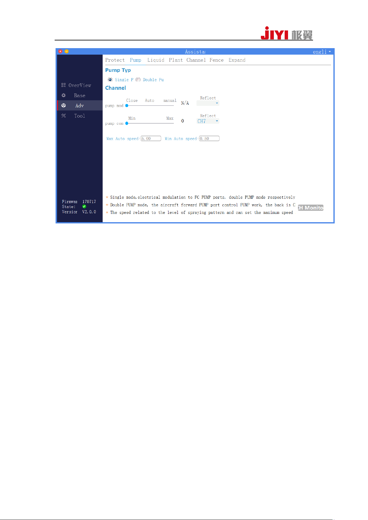
2、Setting: connect to Assistant2 Software, configure the channel to control the water
pump.
Supporting the configurations of the PUMP by both Assistant2 Software and
APP.
Assistant Software setting:connect to Assistant2 Software and enter the path of
“Adv”—“Pump”.
APP setting: use data-link to connect the FCU. Please refer to the port definitions
table.
JIYI Robotics CO. Ltd
Page 21
21
5.2.4 Terrain following function
Under the function, the aircraft can keep the fixed height above ground during
flying.
To use the function, you need a radar module.
1、Connection :connect the radar to the EXT port of the FCU;
2、Setting Up:Setting up the radar facing downwards in the inferior part of the aircraft.
Make sure no shielding barriers are in the range of 30CM diameter. Make sure it is
firmly, no offset, no loosing and be dropped to ground during landing.
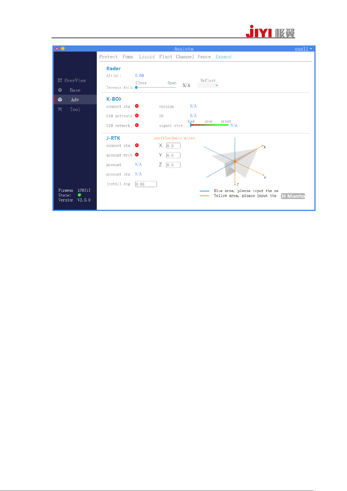
3 Test:when you connect the radar to flight controller, you can test in Assistant2
Software and APP whether the radar works normally or not .
Supporting the configurations of the PUMP by both Assistant2 Software and
APP.
Assistant Software setting:connect to Assistant2 Software and enter the path of
“Adv”—“Expand”.
APP setting: use data-link to connect the FCU. Please refer to the port definitions
table.
JIYI Robotics CO. Ltd
Page 22
22
5.2.6 GPS Speed Shifting Function
1 Setting:
Supporting the configurations of the GPS Speed Shifting by both Assistant2
Software and APP.
Assistant Software setting:connect to Assistant2 Software and enter the path of
“Adv”—“plant”.
APP setting: use data-link to connect the FCU. Please refer to the port definitions
table.
JIYI Robotics CO. Ltd
Page 23
23
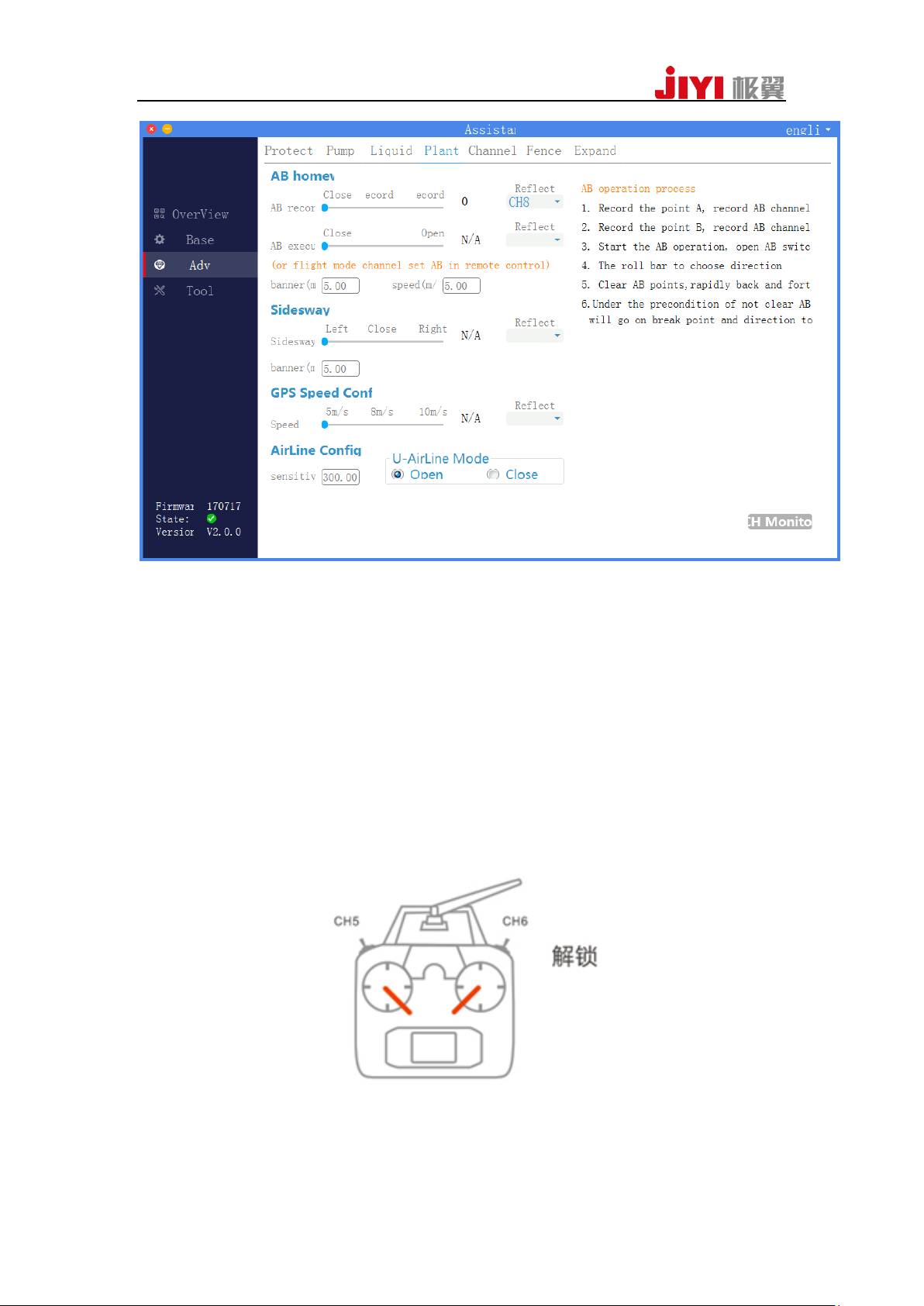
2、Operation:the maximum flight speed can be limited at 5m/s,8m/s or 10m/s by
switching the control stick when the aircraft is flying under GPS speed mode.
5.3 Introduction to the Functions of Remote Controller
5.3.1Arm And Disarm
1.Arm
You can arm the aircraft as is shown in following figure. The motor will be in an
idling status after being armed.
JIYI Robotics CO. Ltd
Page 24
24
2.Disarm
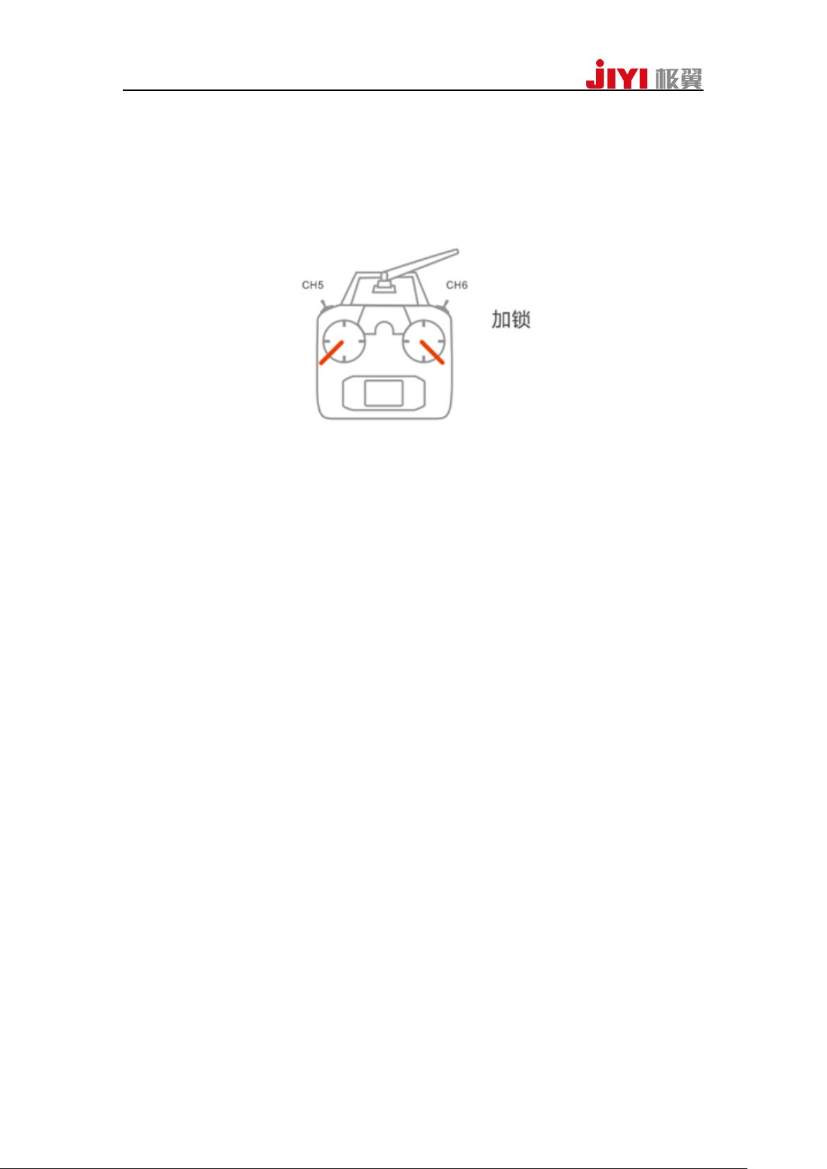
(1)Lmmediate disarmed
under all control modes, as long as motor is turned on, motors will stop spinning
immediately after you pull the sticks as it is shown in following figure.
Note:Do not pull the stick as is shown in the above figure during flight, otherwise the
motor will stop spinning immediately.
(2)Auto disarmed
a.No matter what flight mode it is in, if the aircraft doesn’t take off and at the same
time the throttle is put at lowest level after it is armed, and there are no operations in 3
seconds, the motors will be disarmed automatically.
b.Except in ATT-STA mode, FCU can auto recognize landing, and the aircraft will
stop automatically.
c.Except in ATT-STA mode, if the throttle is put at lowest level, the motor will not
stop spinning.
5.3.2Accelerometer calibration
Flight controller supports horizontal accelerometer calibration with remote controller,
and the calibration method is as follows.
1、Place aircraft horizontally.
2、Switch the return-to-home channel to the highest position, push the control stick of
the remote controller as ↘↗ (American style remote controller) or ↗↘ (Japanese
style remote controller), and when there is an alternating blinking of red, green and
yellow light, accelerometer calibration starts. The calibration will complete in 1 or 2
second(s), and then the LED light will blink normally.
5.3.3Compass Calibration
Flight controller supports compass calibration on remote controller.
JIYI Robotics CO. Ltd
Page 25
25
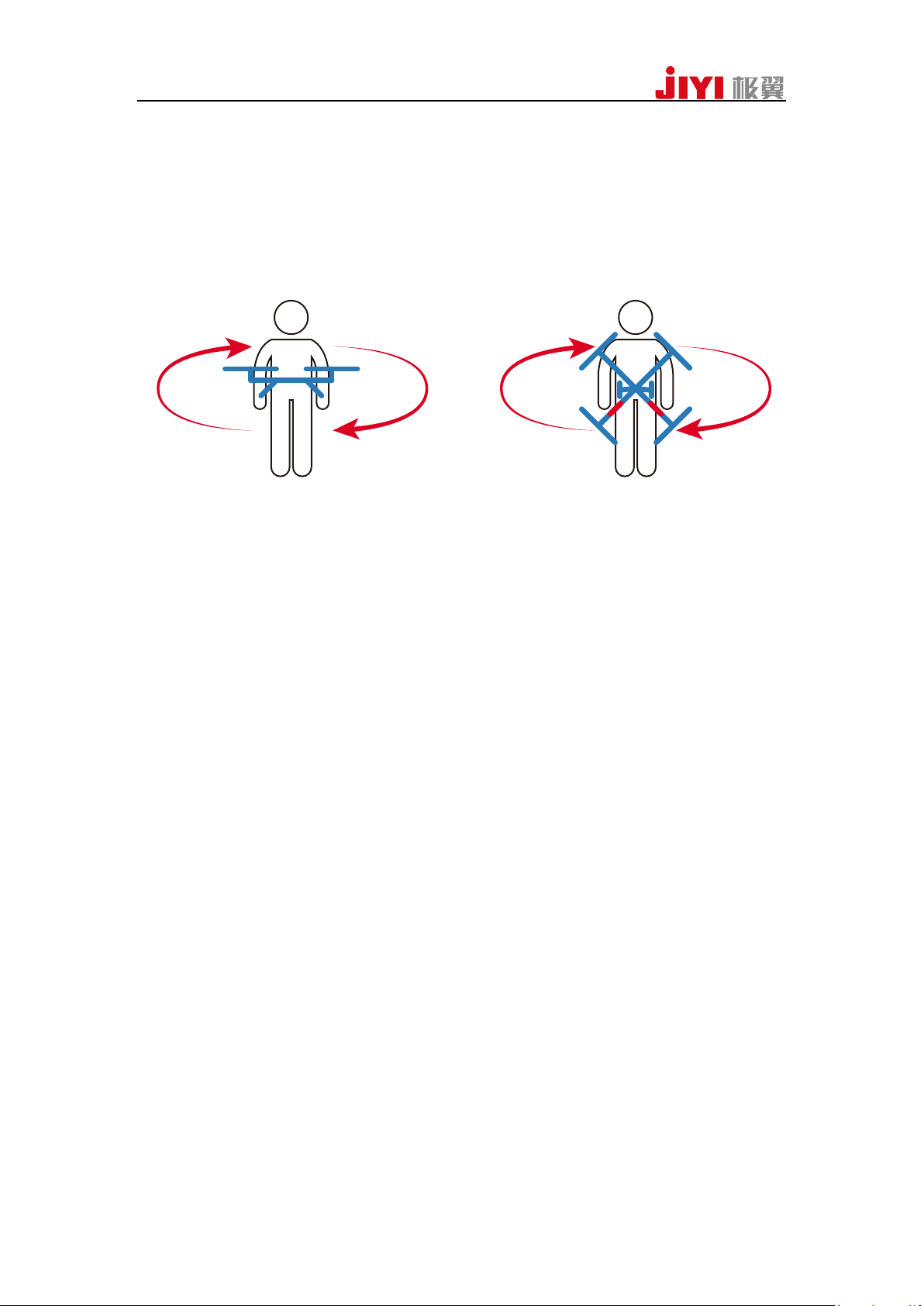
Quickly shift back and forward the 5thchannel before the fight controller is armed,
and then it will enter compass calibration mode. The solid yellow light indicates it is
in horizontal calibration. Place aircraft horizontally at the moment, and do clockwise
rotation around the axis along with the gravity direction. When the LED green light is
solid on, it enters in vertical direction calibration. Put the nose face-down, rotate the
aircraft round the axis along with the gravity direction until the LED red light, green
light and yellow light blink alternately, and that indicates calibration is completed.
After calibration is completed, it will exit from calibration mode automatically,
LED indicatorblinks normally.
Attentions:
When the flight field changes, you need to calibrate magnetic compass.
Before calibration, please check whether there’s strong magnetic interference
nearby or not.
5.3.4 Motor Test
Motor test function includes motor sequence test and movement direction test. It
is mainly used to inspect whether the installation sequence number and rotation
direction of motor are correctly or not . It can avoid the error installation and
accident from happening.
1、Motor Sequence Test
When the aircraft is disarmed, push the LH stick of the remote controller as ↙
prevent
and make the RH stick to do anti-clockwise circling (American style remote
controller), and then the motor sequence testing is triggering. Motors will start idling
spinning in sequence from No.1 motor to No.8 motor.
Japanese style remote controllers: 1. push the LH stick on the remote controller as
↙ and push the RH stick as ↘, keep them in the position. 2. And then push
sequentially the LH stick as ↖, the RH stick as ↙,the LH stick as ↙, the RH stick as
↘. The left rod sha
ll be maintained at the most left side and the right rod shall be
maintained at the most downward side during you push the sticks. Repeat the 4 stick
nd
pushing actions in the 2
step in sequence, the motor sequence test will be triggered.
Attention: Under normal conditions, motor sequence test can be triggered after one
time stick pushing action . But if the sticks are pushed in wrong positions, the motor
sequence test can only be triggered after repeating the 4 stick pushing actions in step
JIYI Robotics CO. Ltd
Page 26
26
2th.
2、Move Direction Test
After the aircraft is armed, the propeller of the aircraft will spin lowly and
steadily in idle speed (power output will be shut down if there is no action in 3s). You
can judge whether the propeller rotates are in reverse direction or not by the remote
controller. For example, when you are pushing the front control stick under the idle
speed, the rear propeller of aircraft should start rotating while the front propeller of
aircraft should stop rotating. Likewise, when you are pushing the left control stick
under the idle speed, the left propeller of aircraft should stop rotating while the right
propeller of aircraft should start rotating.
5.3.5 Fail-safe Protection
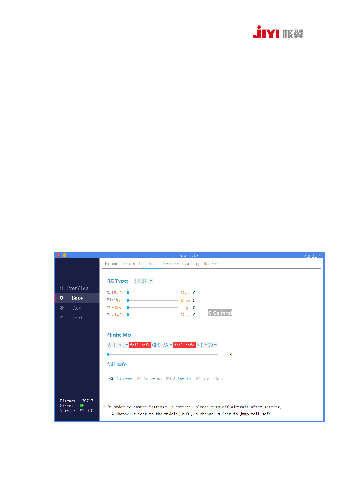
Firstly you are required to set the FS protection of remote controller correctly
according to the user’s manual of remote controller.
Setting in the assiatant2 software (path : Base –RC) .When GPS satellite signal is
good, no matter what kind of aircraft is in, FCU will execute automatic
return-to-home if the signal of receiver is lost. If the signal of remote controller is
recovered during return-to-home, switch the flight mode control channel back and
forward to get control right if you want to control aircraft again.
JIYI Robotics CO. Ltd
Page 27

27
6 User Manual of Mobile Ground Station
Please refer to user manual of mobile ground station for detailed information.
JIYI Robotics CO. Ltd
Page 28

28
Appendix:
Global Feature
Function Description
Supporting PPM and S-BUS receivers
Supporting double GPS
Supporting RTK module
Supporting ground station
Supporting OSD module
Supporting low voltage protection
Supporting FS protection
Peripheral Equipment
Supported Aircraft Module: Axis distance within 1500mm, quadcopter (I4,X4),
hexacopter (I6,X6,Y6,IY6, IY6 coaxial),
octocopter (X8,I8,V8)
Supported ESC: PWM ESC of 490Hz and below
Recommended RC: SBUS receiver
PC system requirement: Windows XP SP3, Windows 7, Window 8, IOS X
Basic Specs
Working Voltage:
Core flight controller: 4.8v to 5.3v
Power module: input 11.1v to 50v (recommended 3S to 12S LiPo), maximum
Appendix1 Product Specification:
JIYI Robotics CO. Ltd
Page 29

29
output 3A@5V
LED Light Module: 5V
Battery voltage: 3S to 12S
Power: less than 2Watt
Working environment temperature: -10℃—60℃
Storage environment temperature: -40℃—60℃
Weights:
Core Flight Controller:56g
GPS/magnetic compass module: 45g
LED light module: 13g
Power Module: 39g
Size:
The Core Flight Controller:53.5mm×40.0mm×21.0mm
GPS/Compass module:63.0mm(diameter)×15.0mm
LED light module:24mm×24mm×8mm
Power Management Module:53.5mm×34.5mm×14.5mm
Flight Performance
Hovering Accuracy: Horizontal:±1.5m
Vertical:±0.5m
Maximum Tilt Angle:30°
Max Yaw Angular Velocity:150°/s
Max Vertical Volocity:6m/s
JIYI Robotics CO. Ltd
Page 30
30
Maximum Wind Resistance: Sustained wind: Force 4
Gusty wind: Force 5
Flight Modes and Functions:ATT-STA Mode, ATT-ALTMode, GPS-SPEED
Mode, GPS-ANGLE Mode,AB Mode, Auto Reuturn to Home Mode, Failsafe
Protection, Low Battery Warning Protection, Cut-out and continue spraying,
One-key Sidesway, Water Pump Control, Terrain Follow, GPS Velocity
Switching,Supporting Datalink and Ground Station, supportting configuration
on mobile phone
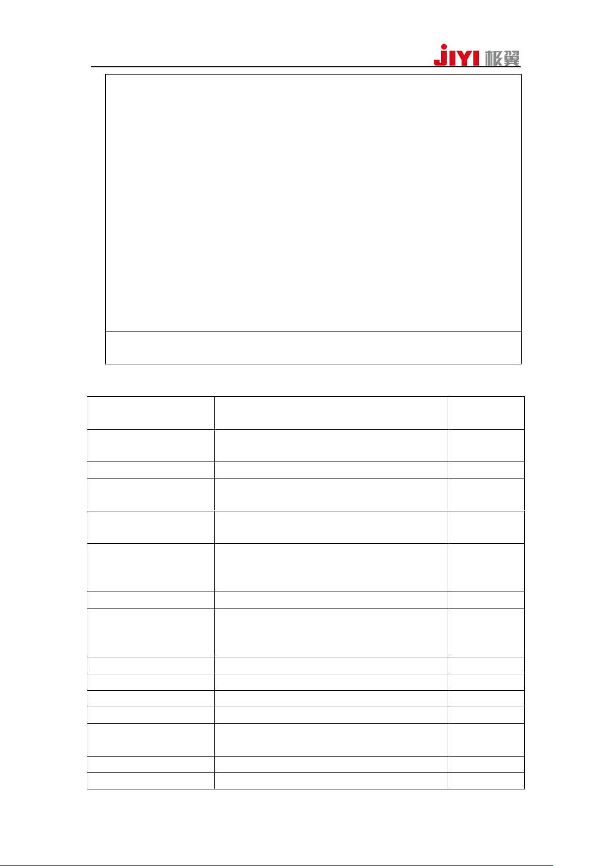
Indication of Flying
Mode
Status Indicator
Priority Level
Attitude(ATT-STA,
ATT-ALT)
green indicator blinks once
Low
GPS mode(angle, speed)
green indicator blinks twice
Low
Function mode(circling,
patrol and agriculture etc)
green indicator blinks three times
Low
Start of intelligence
direction
green indicator blinks four times
Low
Self-driving mode(ground
station control,
return-to-home )
green indicator blinks quickly
Medium
Indication of GPS
Status Indicator
Priority Level
Disconnection of GPS or
GPS didn’t receive the
satellite
red indicator blinks three times
Low
Poor GPS signal
red indicator blinks twice
Low
Ordinary GPS signal
red indicator blinks once
Low
Strong GPS signal
No blink of red indicator
Low
RTK positioning
yellow indicator blinks once
Indication of Low
Voltage Alarm
Status Indicator
Priority Level
Level one alarm
yellow indicator blinks three times
Low
Level two alarm
yellow indicatorblinks quickly
High
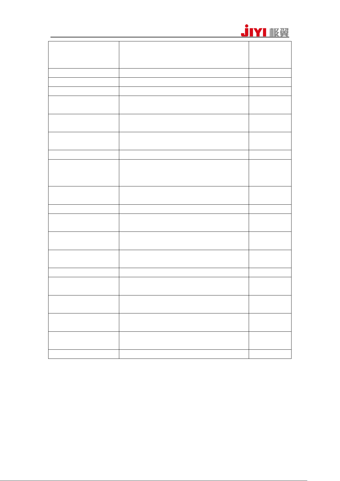
Appendix2:LES STATUS DESCRIPTION
JIYI Robotics CO. Ltd
Page 31
31
Indication of
double-faced
calibration
Status Indicator
Priority Level
Horizontal calibration
Yellow indicator is solidon
Medium
Vertical calibration
Green indicator is solidon
Medium
Calibration failure
Red indicator is solid on
Medium
Calibration success
Alternating blink among red, green and yellow
indicators
Indication of spherical
calibration
Status Indicator
Priority Level
Being calibrated
Alternating blink among red, green and yellow
indicators
Medium
Calibration success
The indicator returns to normal
Medium
Indication
of accelerometer
Calibration
Status Indicator
Priority Level
Being calibrated
Alternating blink among red, green and yellow
indicators
Medium
Calibration success
The green indicator is solidon
Medium
Indication of Abnormal
status
Status Indicator
Priority Level
Lost control of remote
controller
Quick blink of red indicator
High
Compass is disturbed/
abnormal
Alternating blink between green and yellow
indicators
High
GPS loses the signal
Alternating blink betweengreen and redindicators
High
IMU vibration is too
fierce/ abnormal
Alternating blink betweenred and yellow
indicators
High
Indication of Other
Status
Status Indicator
Priority Level
Initialization of power up
Alternating blink among red, green and yellow
indicators
High
Unlock
Alternating blink among red, green and yellow
indicators
High
Unlock failure
Red indicator is normally on
High
Appendix3 :JIYI Technical Suppport
If you have any problem during your usage,please contact JIYI for technical support.
You can download relevant information from JIYI official website.
JIYI Robotics CO. Ltd
Page 32

 Loading...