

Jiuzhou DTT1609 Schematic
service manual
DTT1609

CONTENTS
1 MAIN BOARD TROUBLE SHOOTING GUIDE
1.1 SHORT TEST
1.2 POWER
1.3 MAIN CLOCK
1.4 CVBS
1.5 RGB
1.6 AUDIO
# ADDITIONAL TROUBLESOOTHING
2 SCHEMATIC.COMPONENT LAYOUT AND BOM OF POWER SUPPLY
2.1 SCHEMATIC OF POWER SUPPLY
2.2 COMPONENT LAYOUT OF POWER SUPPLY
3 SCHEMATIC.COMPONENT LAYOUT AND BOM OF MAIN BOARD
3.1 SCHEMATIC OF MAIN BOARD
3.2 COMPONENT LAYOUT OF MAIN BOARD
3.3 BOM OF MAIN BOARD
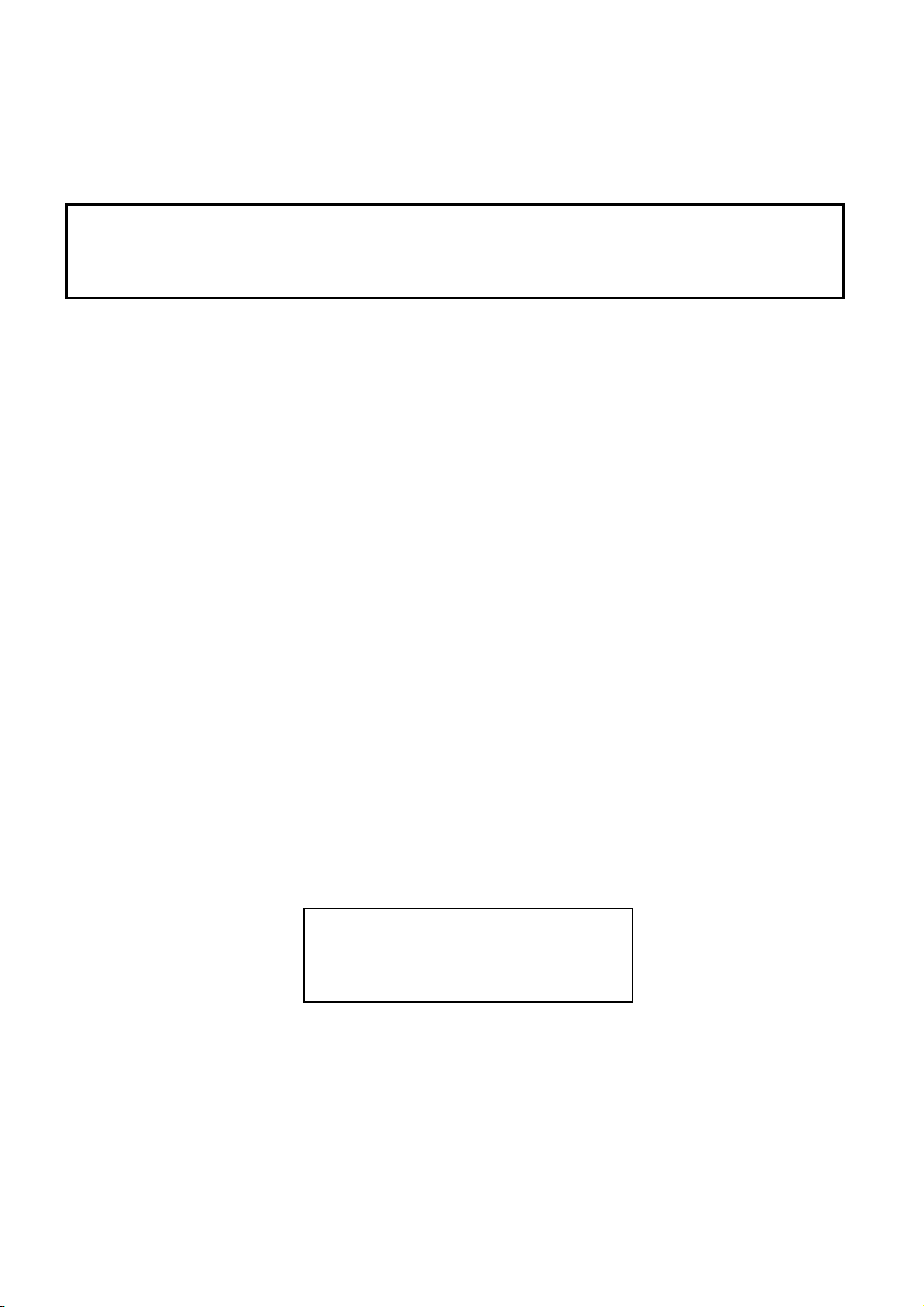
Main Board
8
7
4
2
3
1
9
6
5
10
Main Board Trouble Shooting Guide
(DTT1609)
Here are the procedures you can refer to whenever terrestrial receivers do not
operate properly. You can check problems and repair the units on the basic level
according to the following procedures
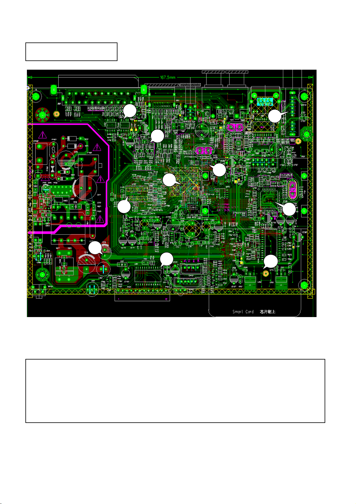
1. SHORT TEST
☞Before turning on AC power, check POSITIVE VOLTAGE and also check whether SHORT
between GROUND's and PIN SHORT for TUNER are detected or not.
1
2. Checking POWER.
☞ +12V(SCART),+5V(ANTENNA_POWER,IR,VIDEO BUFFER,HDMI,USB), +3.3V(TUNER, FLASH,
CPU),+2.5V(DEMOD),+1.5V(DDR3,CPU),+1.3V(CPU DEMOD)
1
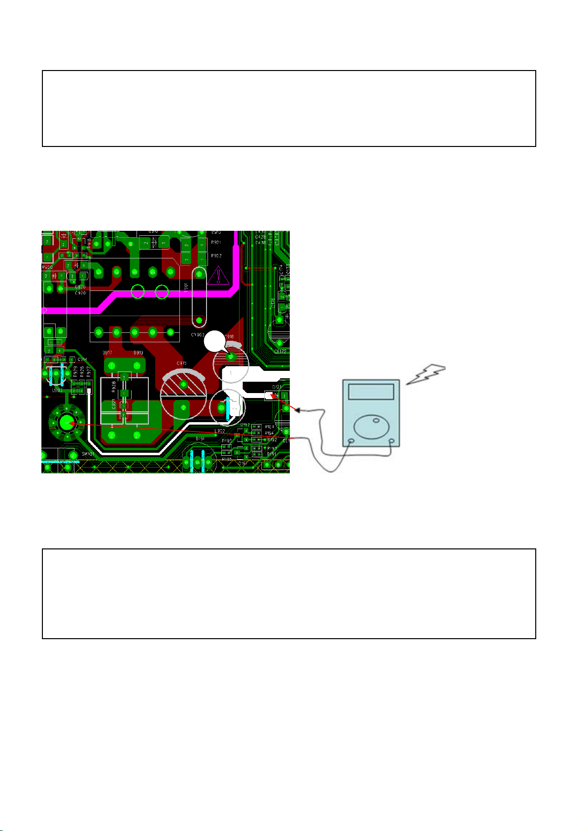
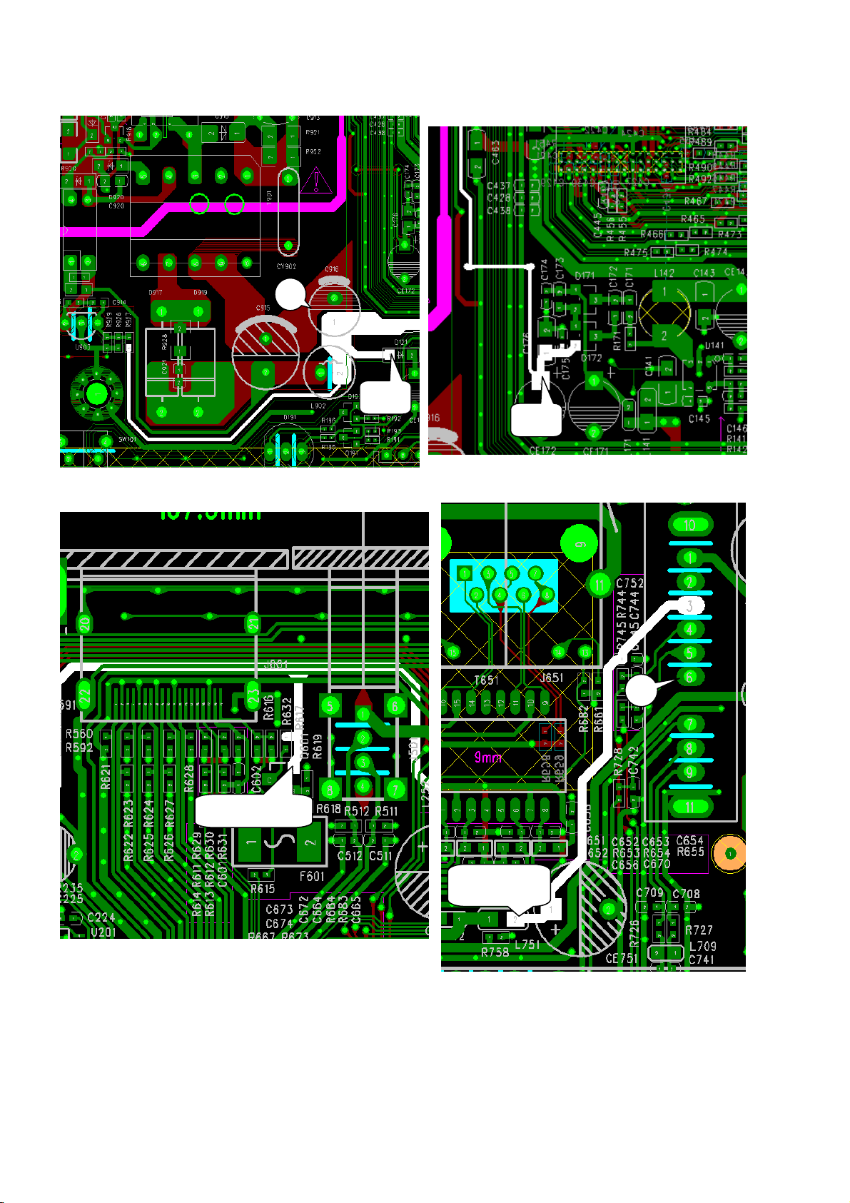
+5V
+12V
6
+5V For HDMI
+3V3 For
Tuner
2
p
p
+3V3
For C
+3V3
10
u
2
+1V5
For C
u
3
Cpu
+1V5 For
DDR3
+1V3 For
10
+2V5 For
DEMOD
5
+1V3 For
DEMOD
8
+5V For
USB
+5V For Video
Buffer
+5V For Audio
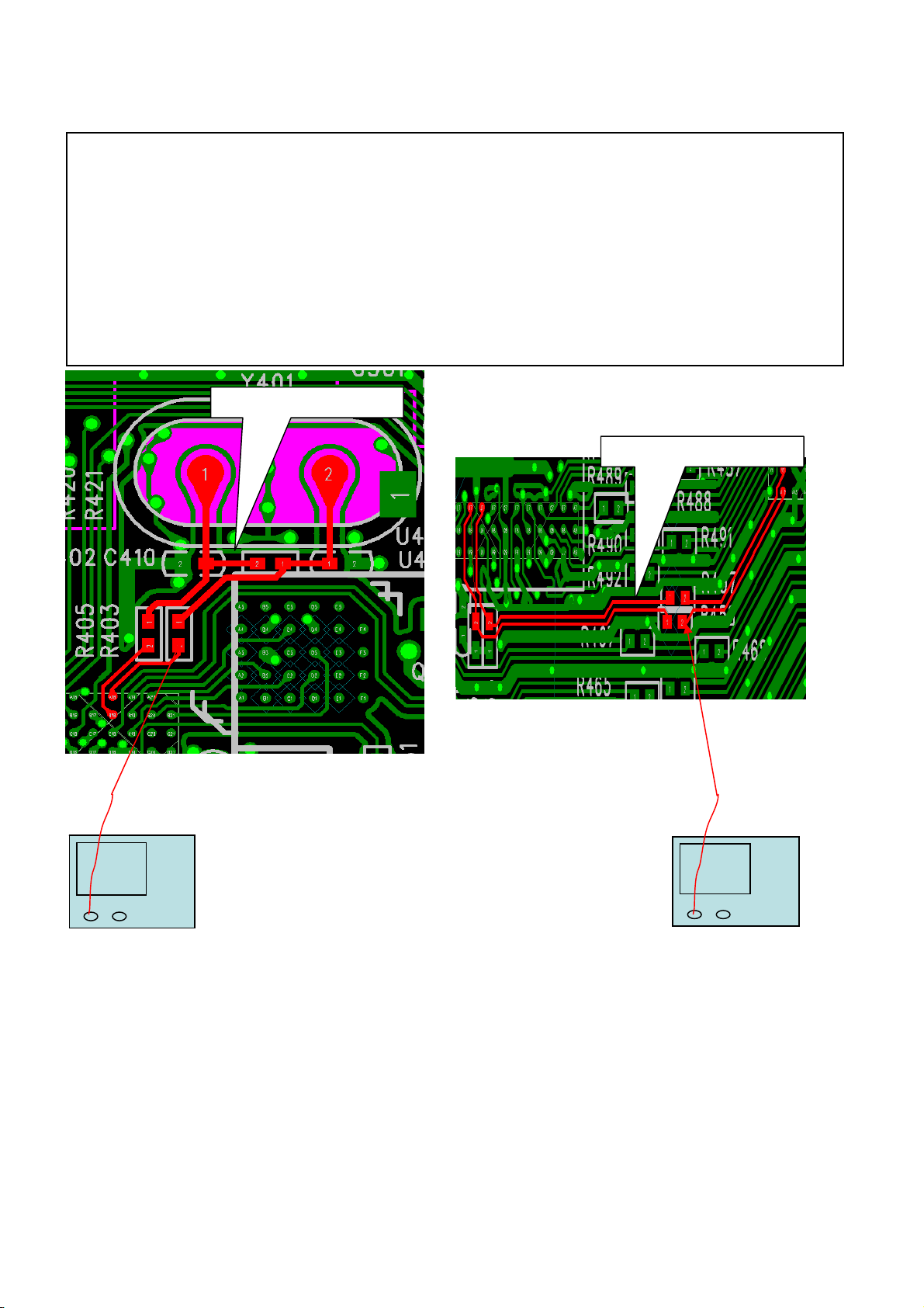
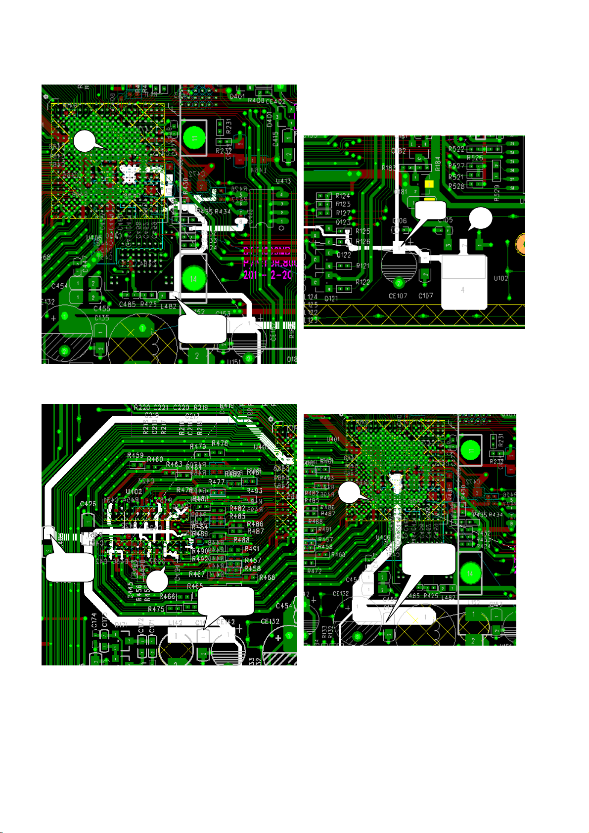
3. Check MAIN CLOCK 24MHz and SYSTEM CLOCK (PLL) to operate normally after SYSTEM
operates.
☞For the first thing, check 24MHz from Y401 flows into [OSCI(PIN B18)] of MAIN
CPU
If the 24MHz is unstable, Check Y401 is damaged or not.
If you are firm belief of damage for the device, then replace the device.
☞ And then, check that 800MHz is being supplied to DDR3 with RESET
If the clock 800MHz on Pin-J7&K7 of U401 is not generated from inside of the
chip,Please check the soldering state of U401,U402 and U403
(MAIN CLOCK) 24MHz
(DDR3 CLOCK) 800MHz
MAIN CLOCK
DDR3 CLOCK 800Mhz

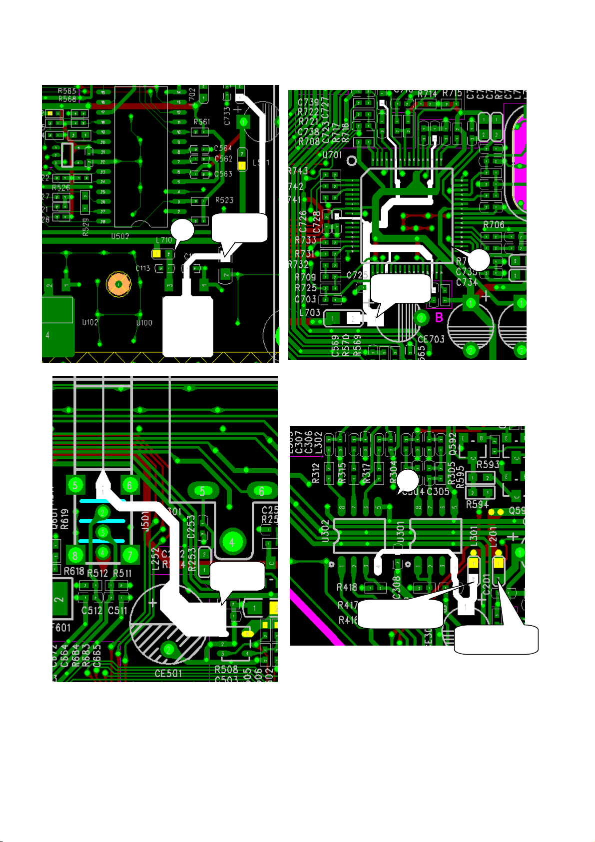
4. In case that MAIN CPU operates normally but there is no VIDEO display.
▶ In case of no OSD display.
☞ If OSD is not displayed, check first if VIDEO SIGNAL is detected from
[R419(CVBS),R416(R),R417(G),R418(B)] of MAIN CPU.
☞ And then, check any part with no DATA after checking VIDEO SIGNAL from VIDEO
SIGNAL PORT of MAIN CPU, or SCART
▶ In case of no MPEG display
☞ There can be a variety of reasons for the case
☞ Check first that CHANNEL of TP SIGNAL is locked properly.
☞ After this signal input to the resistor connected to MAIN CPU is done normally,
A/V DATA comes out from MAIN CPU and flows into MPEG CHIP(MAIN CPU). If there is no
problem to here, it is thought that MAIN CPU and channel are operating without any
fault.
☞ In case of no MPEG display to this point, inspect any disorder by checking
U701(TUNER IC) and I/F of MAIN CPU.
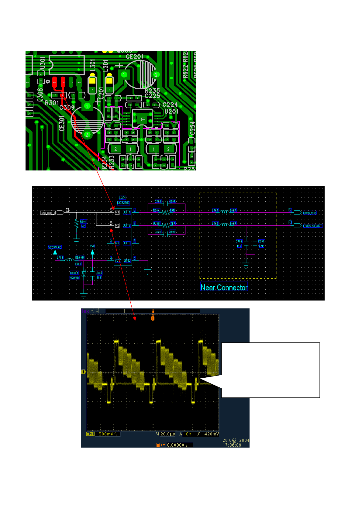
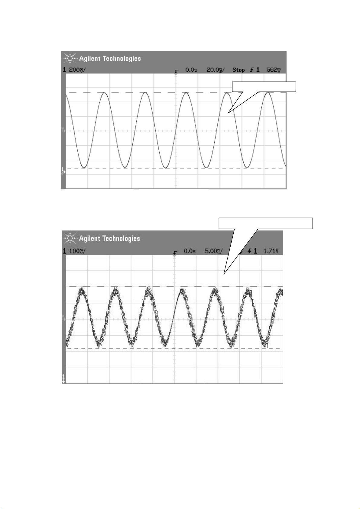
VIDEO SIGNAL
If wave-form is not like this
picture, check that wave-form
output is normal from each
terminal
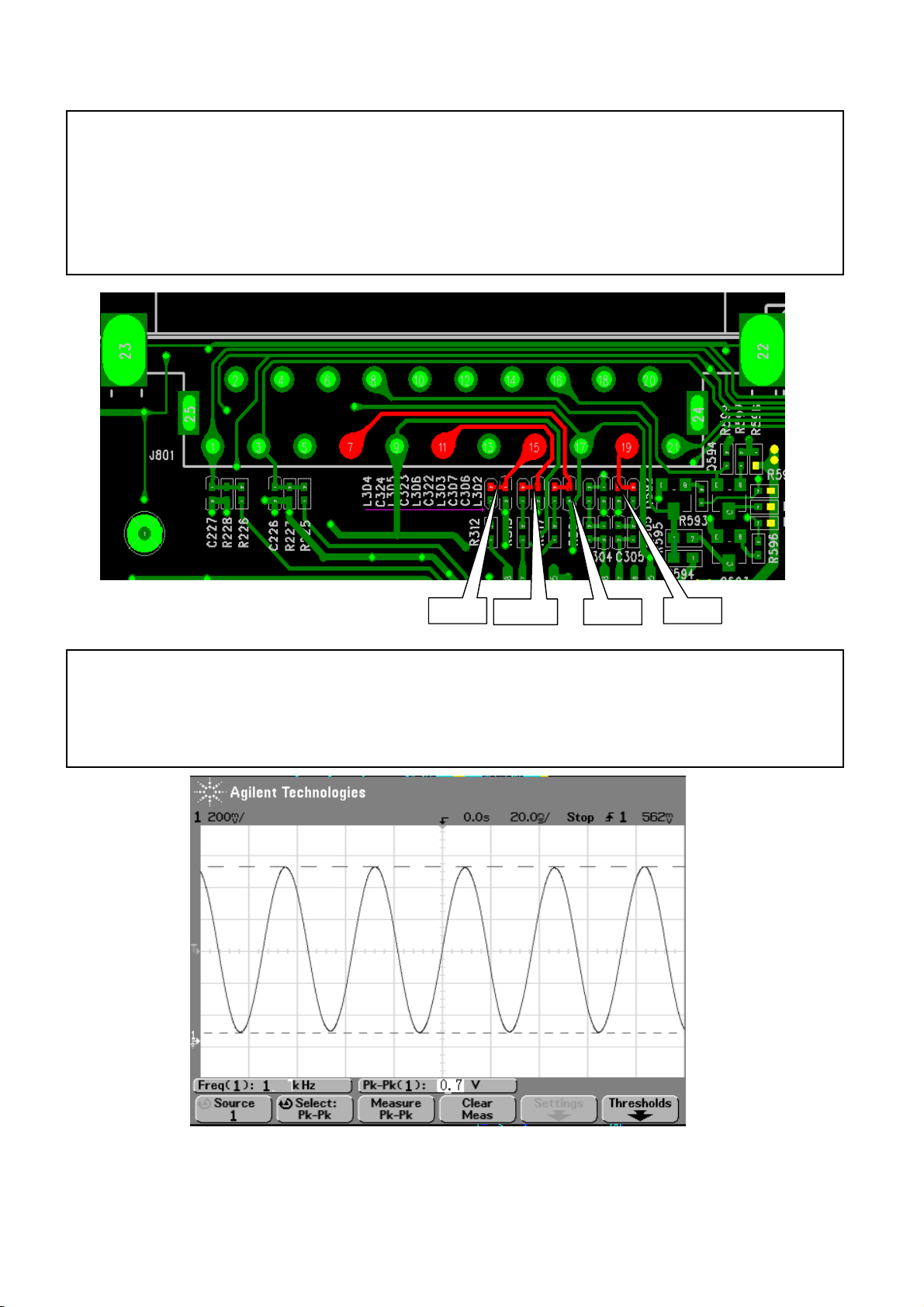
5. In case of no MPEG and no OSD at the same time.
☞ Check that 1Vp_p(0.7Vp_p for RGB) comes out normally from VIDEO PART(CVBS) of
MAIN CPU.
RED CVBS
BLUEGREEN
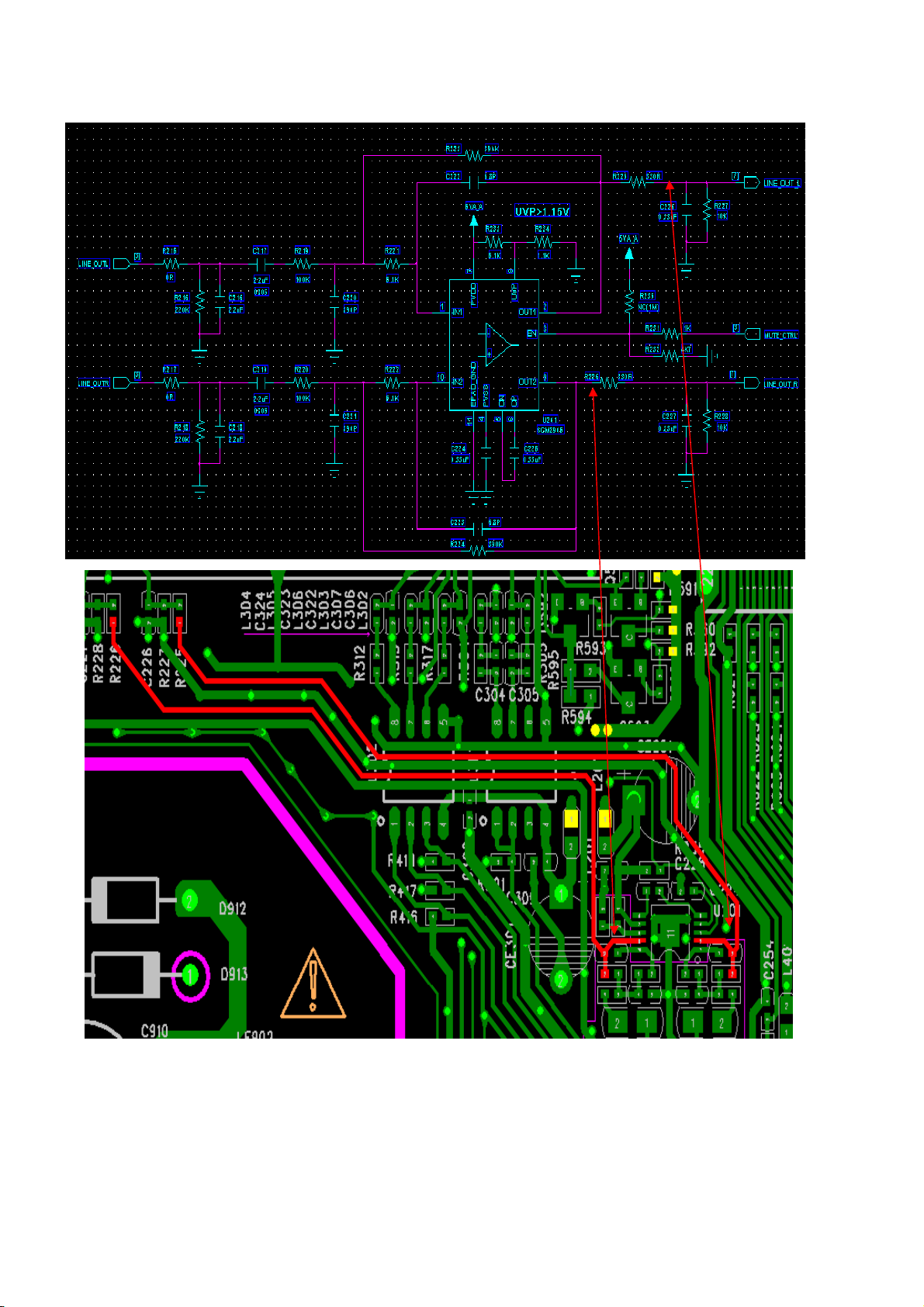
7. In case of normal VIDEO SIGNAL flowing out but abnormal AUDIO SIGNAL.
☞ Check that ADAC_L(U201 PIN2),ADAC_R(U201 PIN9) signals have normal inputting and
outputting from MAIN CPU. The signal is linked to SCART.
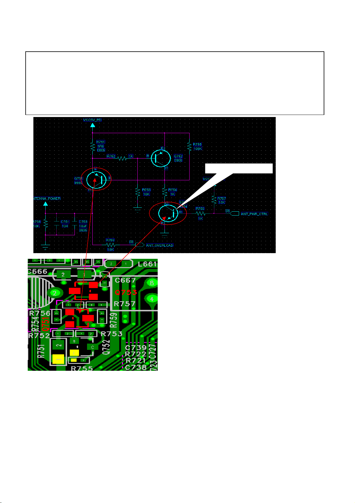
# ADDITIONAL TROUBLESOOTHING
1) STAND-BY mode on Set.
Ordinarily, STAND-BY mode results from SHORT on LNB. Check first if TR on LNB has
stopped, and then in case that STAND-BY mode resulted from wrong software, down-load
a proper software.
POWER SWITCH
There is a TR's as a switching
role on the LNB bundle. 5V comes
out normally from Q751. If
voltage is not enough or steady,
check if the voltage is impressed
properly from Q751.
 Loading...