

Page 1

DJ0050 Rev 03.1
Low Profile, Small Diameter Scanner
Page 2
PAGE i
DJ0050 Rev 03.1
SAFETY WARNINGS / PRECAUTIONS
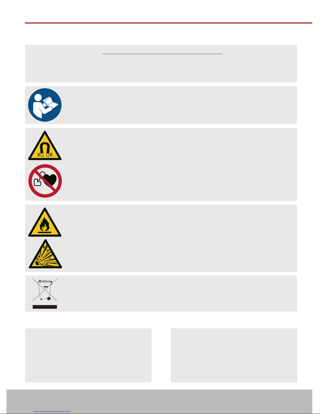
DANGER! The CIRC-IT is designed for a specic use. Using the
CIRC-IT outside of its intended use could cause damage to the product.
Read and understand this manual before using.
KEEP THIS MANUAL – DO NOT LOSE
THIS MANUAL IS PART OF THE CIRC-IT AND MUST BE RETAINED FOR THE LIFE OF
THE PRODUCT. PASS ON TO SUBSEQUENT OWNERS.
Ensure any amendments are incorporated with this document.
WARNING! Can be harmful to pacemaker and ICD wearers. Stay
at least 10 cm (4 in) away.
WARNING! Do NOT operate scanner in an explosive environment.
Do NOT operate scanner in the presence of volatile substances.
The WEEE symbol indicates that the product must not be disposed of as
unsorted municipal waste, but should be collected separately.
(see Disposal on page 36)
Jireh Industries Ltd.
53158 Range Road 224
Ardrossan, Alberta, Canada
T8E 2K4
Phone: (780) 922-4534
Fax: (780) 922-5766
jireh-industries.com
DISTRIBUTOR: MANUFACTURER:
Page 3

PAGE ii
Chapter
1
Introduction 1
1.1. Product information 1
1.1.1. Intended use 1
1.1.2. Performance specifications 1
1.1.3. Operating environment 1
1.1.4. Environmental Sealing 1
1.2. Definition of symbols 2
1.3. Hardware 2
1.3.1. Included tools 2
1.3.2. Maintenance 3
1.4. Circ-it Configuration Chart 4
Chapter
2
Preparation for Use 5
2.1. Scanner Component Identification 5
2.2. Scanner Identification (Single Side) 6
2.3. Scanner Identification (Dual Side) 7
Chapter
3
Configurations 8
3.1. Single Probe 8
3.2. Dual Probe 8
Chapter
4
Operation 9
4.1. Setup of Circ-it on a Pipe or Tube 9
4.1.1. Setup on diameters smaller than 31.75 mm (1.25 in) 13
4.2. Single Probe Scanner Setup 14
4.3. Installing Wedges 15
4.4. Sleeve Setup 18
4.5. Setting Wedge Spacing 23
4.5.1. Wedge Separation Indicators 25
4.6. Circ-it Setup (Single-Sided Access) 28
4.7. Latch Connection 32
4.8. Link Connection 33
4.8.1. Correct Link Configuration 34
TABLE OF CONTENTS
Page 4

PAGE iii
DJ0050 Rev 03.1
Chapter
5
Service and Repair 35
5.1. Troubleshooting 35
5.2. Technical Support 35
5.3. Disposal 36
Chapter
6
Spare Parts 37
6.1. Circ-it Kit Components 37
6.2. Circ-it Scanner 38
6.2.1. Encoder Connector Type 40
6.3. Accessories 40
6.3.1. Crossbars 40
6.3.2. Circ-it Spare Parts Kit 40
Chapter
7
Limited Warranty 41
Page 5

PAGE iv
Page 6

PAGE 1
DJ0050 Rev 03.1
CHAPTER 1
INTRODUCTION
1.1. Product information
1.1.1. Intended use
The CIRC-IT is a manual small diameter, low prole scanner. It is designed
to provide encoded probe positioning, circumferentially, around piping and
tubing.
1. The intended scan surface is to:
►
free of debris, scale, soot, etc
►
no smaller than 21.3 mm (0.84 in) outer diameter
►
no larger than 114.3 mm (4.5 in) outer diameter
2. The CIRC-IT is intended for both dual and single probe scanning
applications.
1.1.2. Performance specications
Minimum Maximum
Scanner Diameter Range 21.44 mm (0.84 in) 114.30 mm (4.5 in)
Scanner Width 53.5 mm (2.11 in)
Encoder Resolution 31.30 counts/mm (795.0 counts/inch)
Required Radial Clearance* 11.0 mm (0.433 in)
* Scanner only. Transducers and wedges not included.
1.1.3. Operating environment
The CIRC-IT is designed for use in industrial environments that are between
-20° C (-4° F) and 50° C (122° F).
1.1.4. Environmental Sealing
Dust tight, water tight (not submersible).
Page 7
PAGE 2
1.2. Denition of symbols
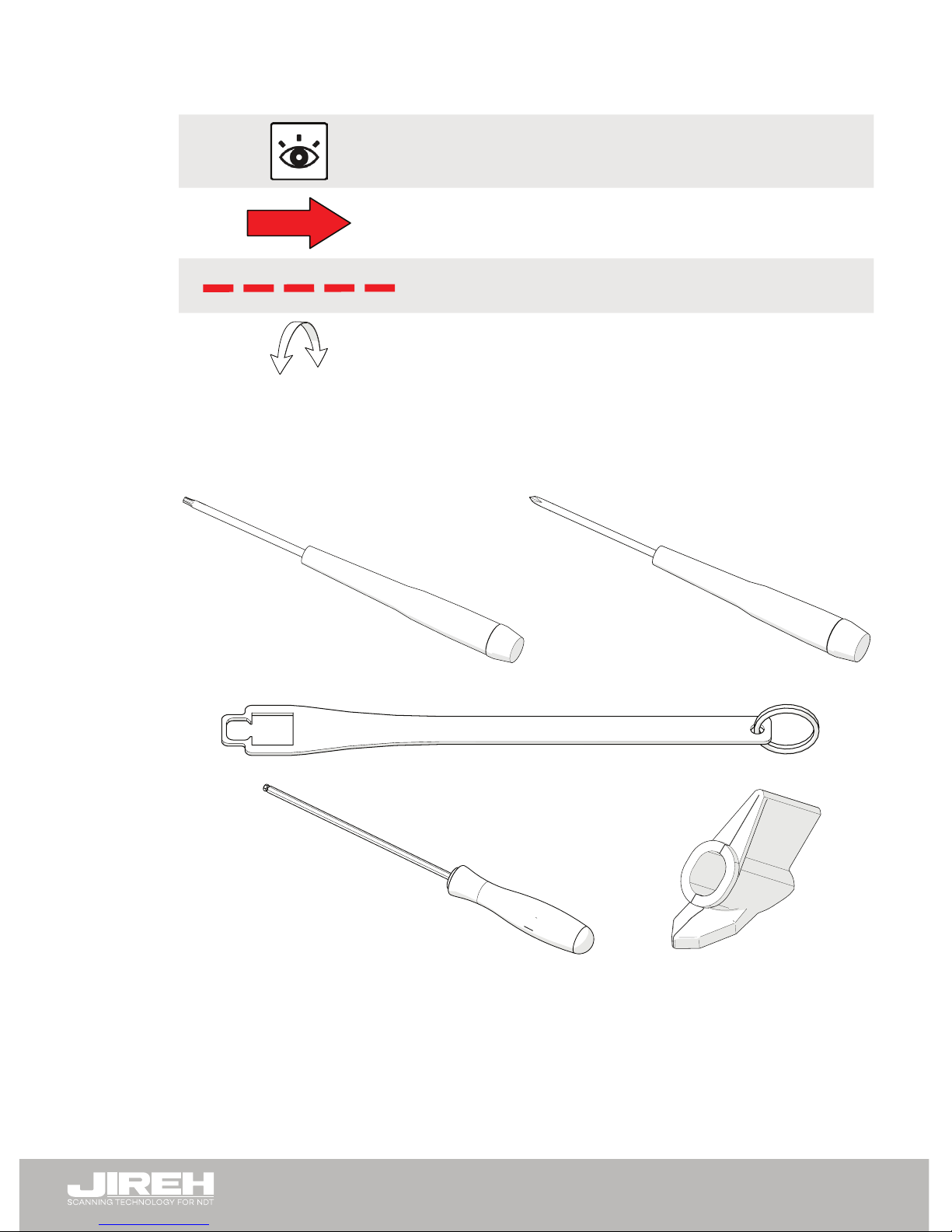
Instructions to ‘look here’ or to ‘see this part’
Denotes movement. Instructing user to carry out
action in a specied direction.
Indicates alignment axis, can also indicate
insertion or movement of parts.
Alerts user that view has changed to a reverse
angle.
1.3. Hardware
1.3.1. Included tools
►
The Torx® driver (Fig. 1) is sufcient for typical operations and
adjustments of the CIRC-IT.
►
The Phillips driver (Fig. 2) is sufcient for typical operations and adjustments of the CIRC-IT.
Fig. 1 - Torx® driver
Fig. 2 - Phillips driver
Fig. 3 - Chain retrieval tool
Fig. 4 - 2 mm hex driver
Fig. 5 - Loom installation tool
Page 8

PAGE 3
DJ0050 Rev 03.1
►
The chain retrieval tool (Fig. 3) is used when installing the scanner
during single sided access situations.
►
The 2 mm hex driver is required for removal of the encoder cable guard.
►
The loom installation tool (Fig. 5) is used for setup of the scanner’s
sleeving.
1.3.2. Maintenance
General cleaning of components is important to keep your system working
well. All components that have no wiring or cables are completely waterproof.
Components can be washed with warm water, dish soap and a medium bristle
brush.
Before using the scanner, ensure all connectors are free of water and
moisture.
NOTE: All components with wiring, cables or electrical connections are splash
proof. However, these components are NOT submersible.
NOTE: Never use strong solvents or abrasive materials to clean your scanner
components.
Page 9

PAGE 4
1.4. Circ-it Conguration Chart
CIRC-IT: Setup Chart
MIN
(in)
MAX
(in)
MIN
(mm)
MAX
(mm)
SHORT MEDIUM LONG WHEEL
0.84 0.94 21 24 0 0 0 0 0.84 0.88
0.94 1.03 24 26 1 0 0 0 1.00
1.02 1.11 26 28 0 0 0 1 1.05
1.11 1.20 28 30 1 0 0 1 1.13
1.20 1.28 30 33 0 0 0 2
1.28 1.37 33 35 1 0 0 2 1.32 1.32
1.37 1.45 35 37 0 0 0 3 1.38
1.45 1.53 37 39 1 0 0 3 1.50
1.53 1.62 39 41 0 0 0 4
1.61 1.70 41 43 1 0 0 4 1.66
1.70 1.78 43 45 0 0 0 5 1.75
1.78 1.86 45 47 1 0 0 5
1.86 1.95 47 49 0 0 0 6 1.90
1.94 2.03 49 51 1 0 0 6 2.00
PIPE OD
(in)
TUBE OD
(in)
LINK T YPEOUTER ∅ RANGE
MIN
(in)
MAX
(in)
MIN
(mm)
MAX
(mm)
SHORT MEDIUM LONG WHEEL
PIPE OD
(in)
TUBE OD
(in)
LINK T YPEOUTER ∅ RANGE
2.01 2.15 51 55 0 1 0 5
2.14 2.28 54 58 1 2 0 4 2.25
2.27 2.41 58 61 0 3 0 4 2.38
2.38 2.52 61 64 0 2 0 6 2.50
2.51 2.64 64 67 1 3 0 5 2.50
2.64 2.77 67 70 0 4 0 5
2.76 2.89 70 73 0 1 2 4 2.88
2.88 3.01 73 76 0 3 1 5 2.88
2.99 3.12 76 79 0 0 3 4 3.00
3.11 3.24 79 82 0 2 2 5
3.23 3.37 82 86 0 4 1 6 3.25
3.34 3.47 85 88 0 1 3 5
3.47 3.60 88 91 0 3 2 6 3.50 3.50
3.57 3.70 91 94 0 0 4 5
3.69 3.83 94 97 0 2 3 6 3.75
3.80 3.93 96 100 1 0 4 6
3.92 4.05 100 103 0 1 4 6
4.00 4.13 101 105 1 1 4 6 4.00 4.00
4.12 4.25 105 108 0 2 4 6
4.19 4.32 106 110 1 2 4 6
4.31 4.45 110 113 0 3 4 6
4
.42 4.55 112 115 1 1 5 6 4.50 4.50
4.54 4.67 115 119 0 2 5 6
LONG LATCH REQUIRED
SHORT LATCH REQUIRED
DJ0051 Rev 04
Fig. 6 - Conguration chart
Page 10
PAGE 5
DJ0050 Rev 03.1
CHAPTER 2
PREPARATION FOR USE
2.1. Scanner Component Identication
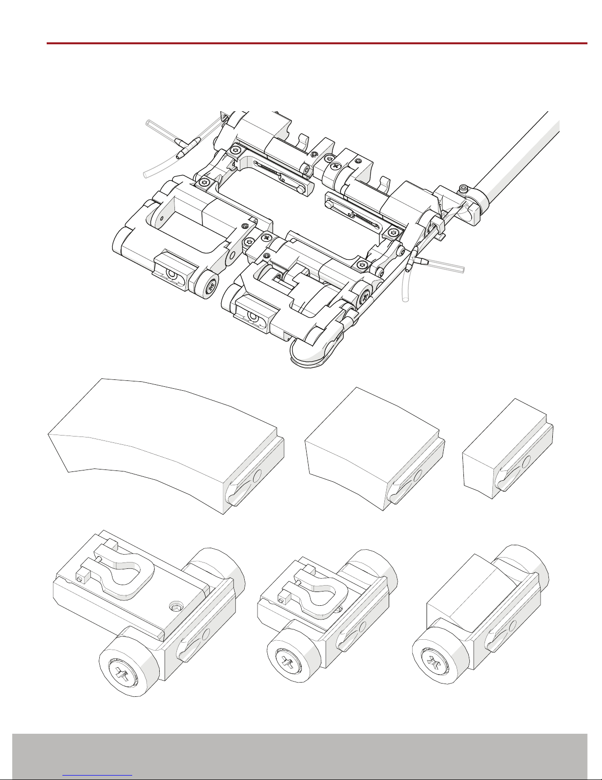
Fig. 7 - Circ-it Scanner
Fig. 8 - Long link
Fig. 9 - Medium link
Fig. 10 - Short link
Fig. 11 - Long latch
Fig. 12 - Short latch Fig. 13 - Wheel block
Page 11
PAGE 6
2.2. Scanner Identication (Single Side)
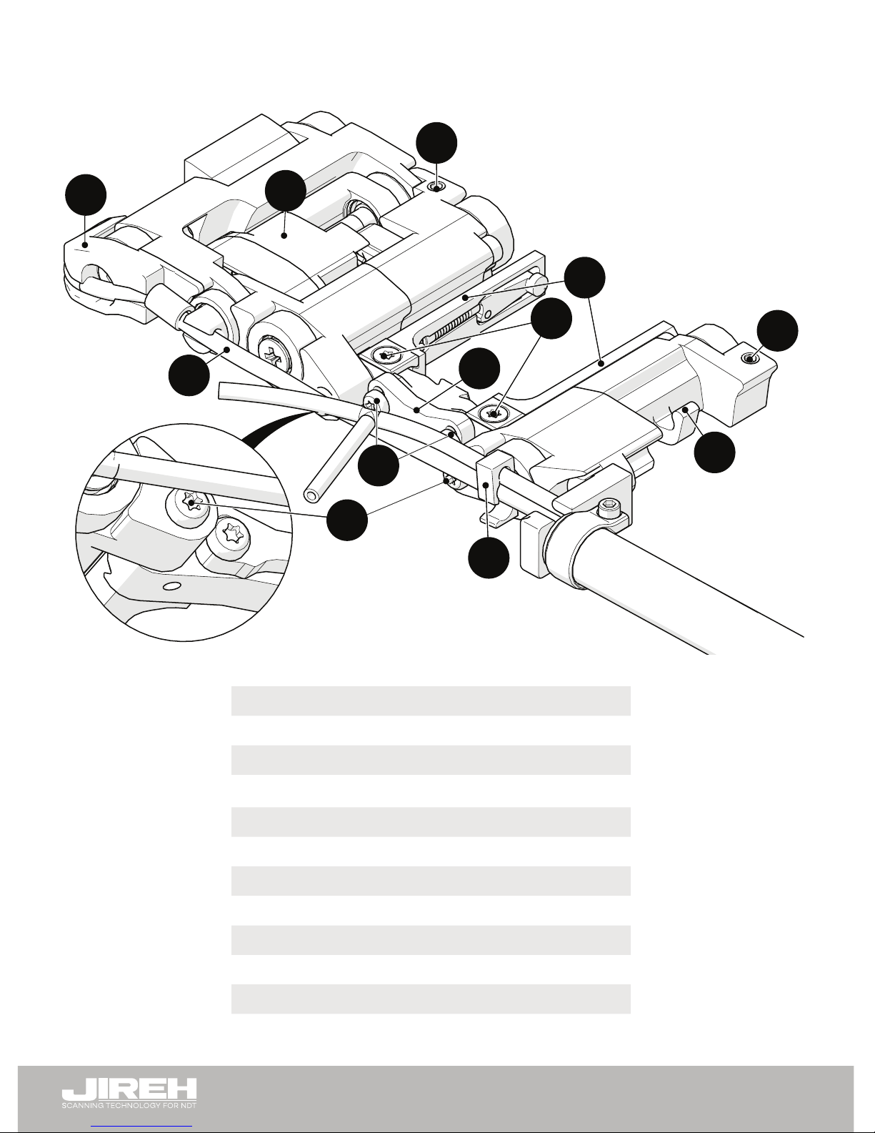
A
Encoder Cable Guard
B
Encoder
C
Crossbar Retaining Screw
D
Probe Holder Arm
E
Probe Holder Adjustment Screw
F
Setup Tab
G
Encoder Cable
H
Setup Tab Screws
I
Pivot Adjustment Screw
J
Cable Management Clip
K
Latch Hook
B
D
G
E
C
F
K
J
C
A
B
H
I
Fig. 14 - Scanner component identication (single side)
Page 12
PAGE 7
DJ0050 Rev 03.1
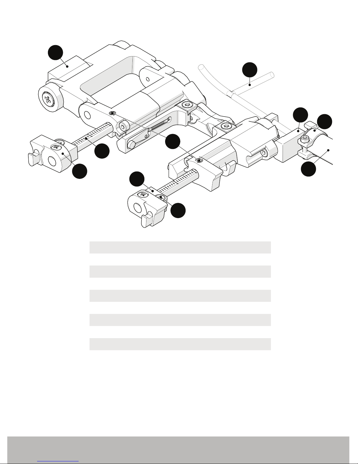
2.3. Scanner Identication (Dual Side)
L
Link Mount
M
Crossbar
N
Crossbar Clamp Bracket
O
Wedge Separation Indicator
P
Crossbar Clamp Screw
Q
Wedge Separation Indicator Clamp Screw
R
Irrigation Tube
S
Sleeve Clamp Bracket
T
Sleeve Clamp
U
Sleeve
Fig. 15 - Scanner component identication (dual side)
L
M
U
O
Q
R
N
P
T
S
Page 13
PAGE 8
CHAPTER 3
CONFIGURATIONS
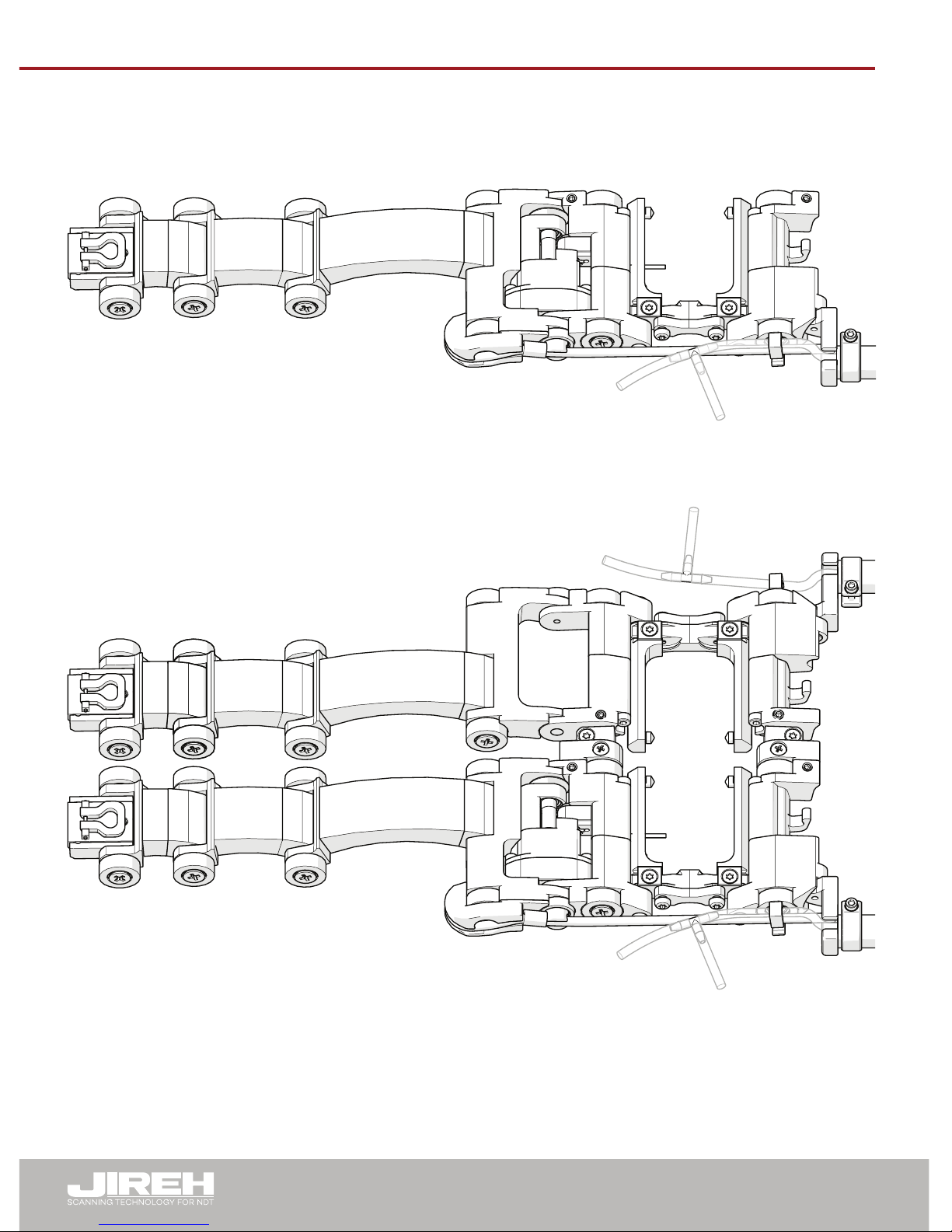
3.1. Single Probe
3.2. Dual Probe
Fig. 16 - Single probe scanning
Fig. 17 - Dual probe scanning
Page 14
PAGE 9
DJ0050 Rev 03.1
CHAPTER 4
OPERATION
4.1. Setup of Circ-it on a Pipe or Tube
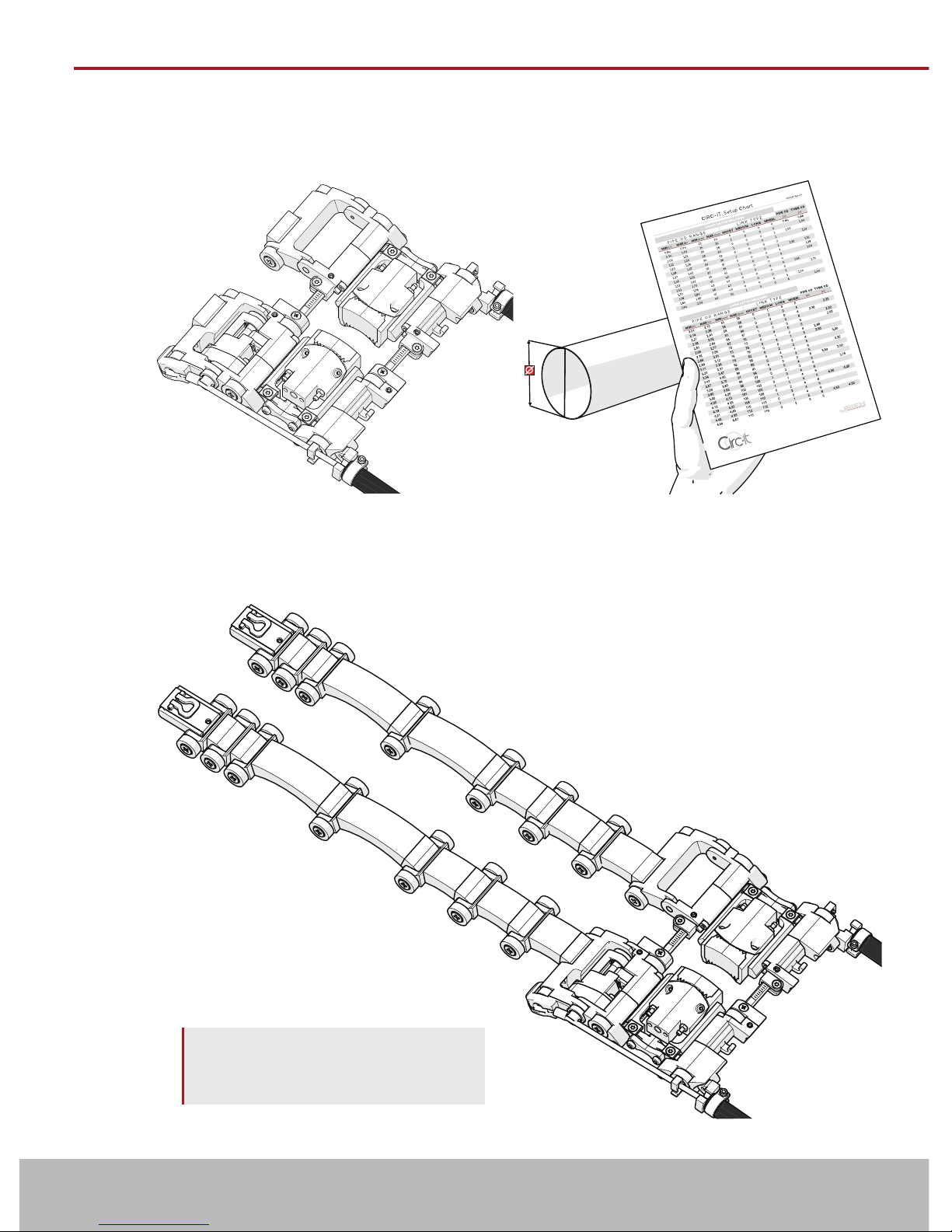
1. Install the wedges (see Installing Wedges on page 15) as well as set the desired
probe spacing (see Setting Wedge Spacing on page 23) (Fig. 18).
2. Determine the diameter of the pipe or tube to be
scanned. Included in the CIRC-IT kit is a setup
chart which will indicate the number of links,
wheel blocks and type of latch required
based on the pipe/tube diameter
(Fig. 19).
3. Assemble the
appropriate conguration of
links, wheel blocks and latches
(see Link Connection on page 33) to
the scanner body (Fig. 20).
TIP: This example provided is a
conguration for a 3.5 inch
tube diameter.
Fig. 18 - Set wedge spacing
Fig. 19 - Refer to setup chart
Fig. 20 - Assemble links on a at surface
Page 15
PAGE 10
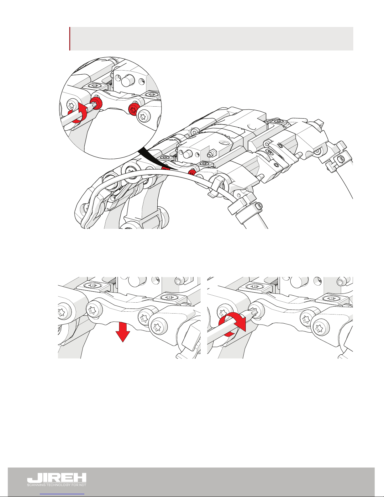
NOTE: Alternate wheel blocks and links ensuring links are always separated by a
wheel block (see Correct Link Conguration on page 34).
4. Loosen the two screws (Fig. 14-H) on either side of the setup tab (Fig. 14-F), do
not remove these screws, a 1/4th turn should be sufcient. Perform this task on
both sides of the scanner (Fig. 21).
5. Lower the setup tab on both sides of the scanner (Fig. 22).
6. Tighten the screws of the setup tabs (Fig. 23).
Fig. 21 - Loosen the setup tab screws
Fig. 22 - Lower setup tab Fig. 23 - Tighten screws
Page 16
PAGE 11
DJ0050 Rev 03.1
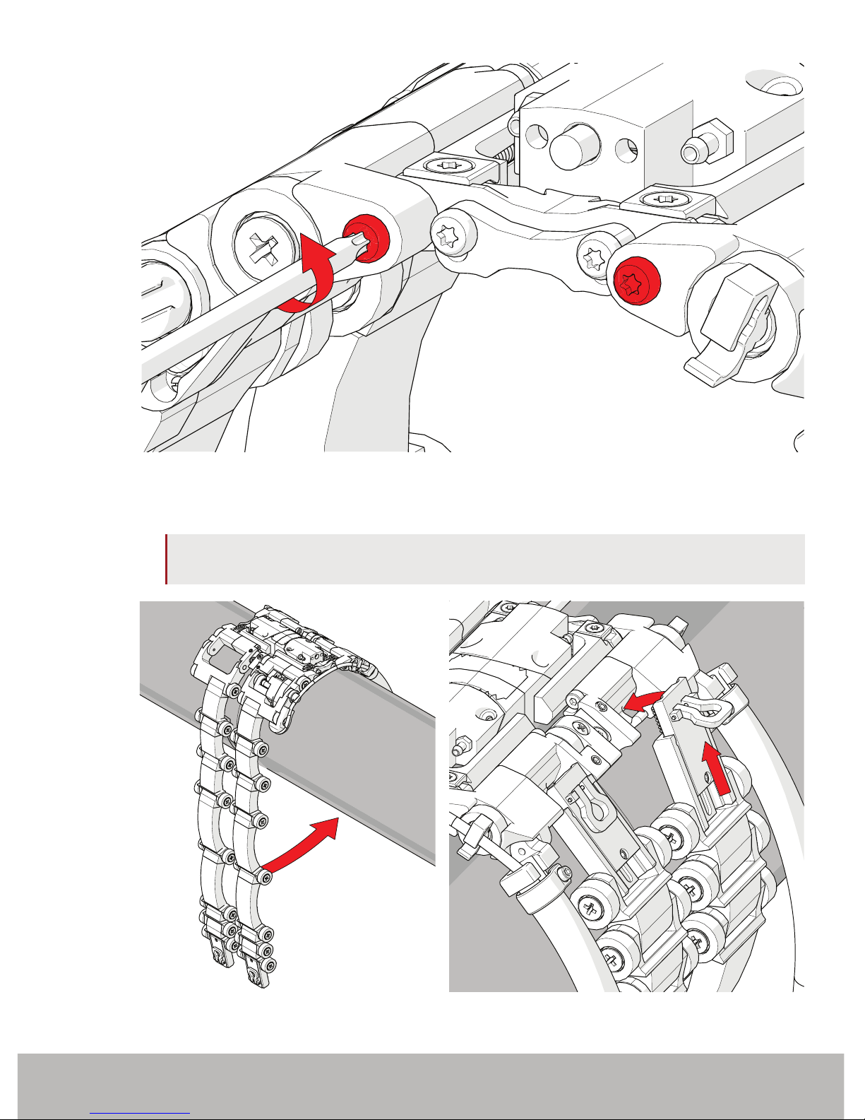
7. Loosen the pivot adjustment screws (Fig. 14-I) of the scanner 1/8
th
of a turn
(Fig. 24).
NOTE: It is unnecessary to loosen pivot adjustment screws beyond a 1/8th turn.
Doing so can hinder proper scanner setup.
Fig. 24 - Loosen pivot adjustment screws
Fig. 25 - Wrap scanner around pipe/tube Fig. 26 - Pull and fasten latches
Page 17
PAGE 12
8. Wrap the scanner around the pipe or tube (Fig. 25).
9. Bring the scanner body around the pipe/tube. Pull and fasten latches (see Latch
Connection on page 32) to the latch hooks (Fig. 14-K) of the scanner. (Fig. 26).
Ensure the latch is in the at position prior to scanning.
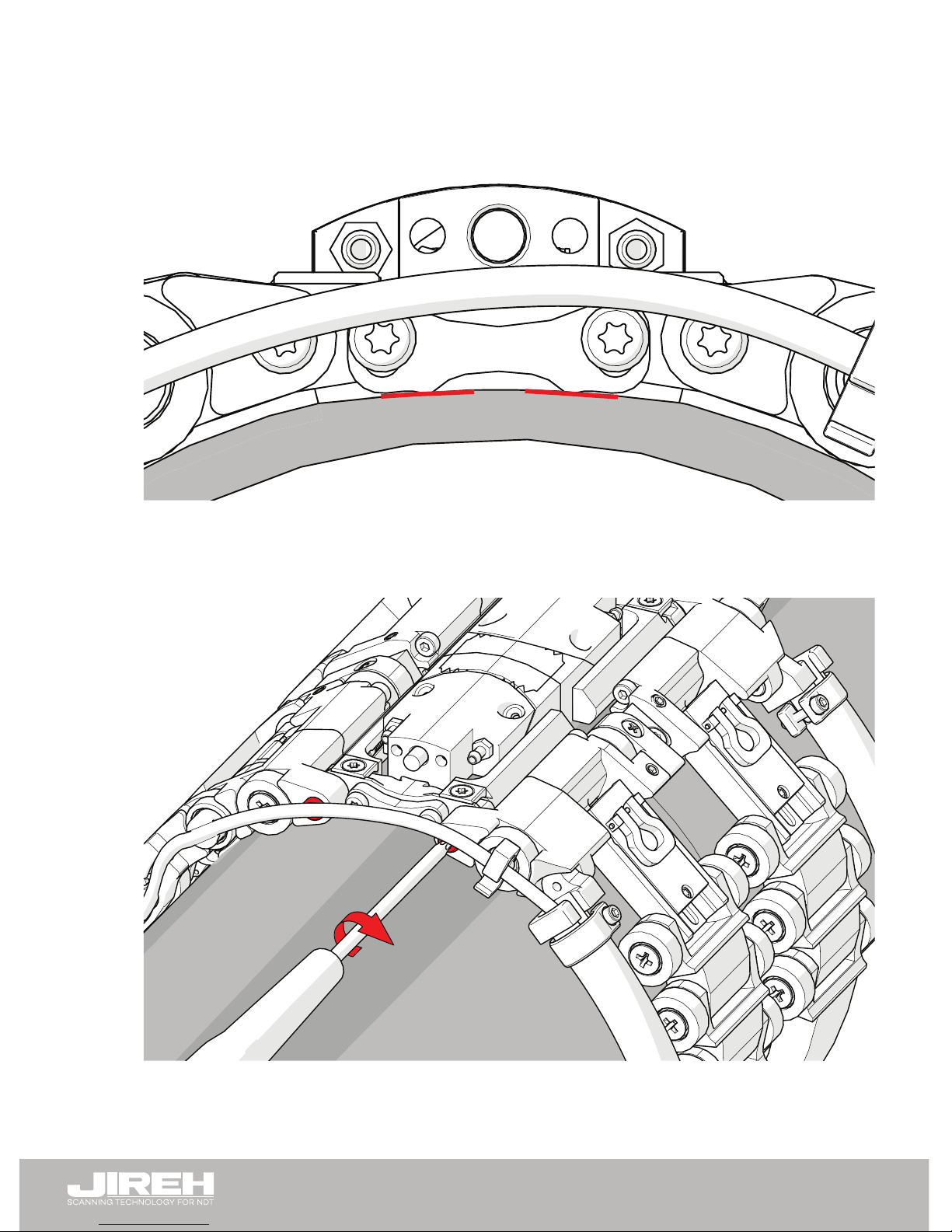
10. Ensure that all wheels and both indicator points of the setup tab are contacting
the tube/pipe surface (Fig. 27).
11. Tighten the pivot adjustment screws on both sides of the scanner (Fig. 28).
Fig. 27 - Ensure setup tab contacts scan surface
Fig. 28 - Tighten pivot adjustment screws
Page 18
PAGE 13
DJ0050 Rev 03.1
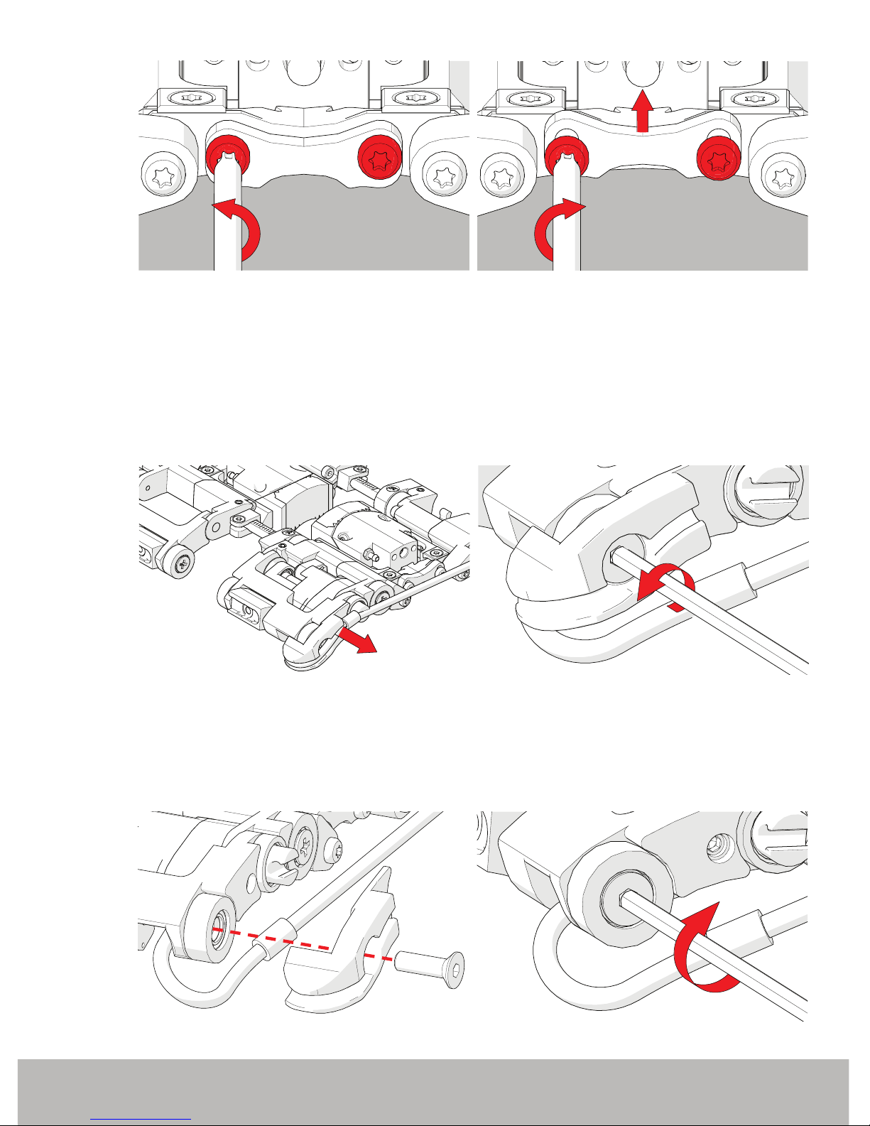
12. Loosen the screws of the setup tab on both sides of the scanner (Fig. 29).
13. Lift the setup tabs of the scanner and tighten the screws (Fig. 30).
4.1.1. Setup on diameters smaller than 31.75 mm (1.25 in)
Low clearance scanning on diameters smaller than 31.75 mm (1.25 in) may
require removal of the encoder cable guard (Fig. 14-A).
1. Remove the encoder cable from the clips along the side of the scanner
(Fig. 31).
2. Use the supplied 2 mm hex driver (Fig. 4) to remove the screw from the
wheel and encoder cable guard (Fig. 32).
Fig. 29 - Loosen setup tab screws
Fig. 30 - Lift setup tab and tighten screws
Fig. 31 - Remove encoder cable from clips Fig. 32 - Remove screw
Fig. 33 - Remove encoder cable guard Fig. 34 - Replace screw
Page 19
PAGE 14
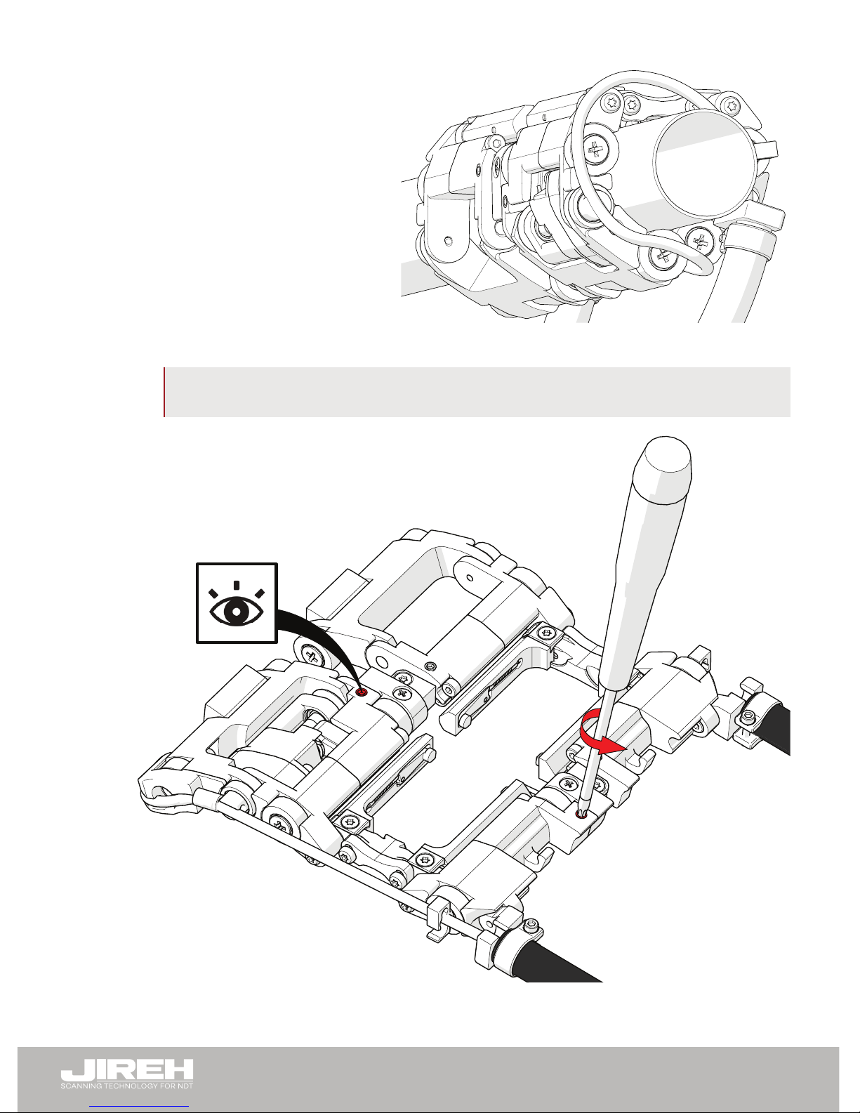
3. Remove the encoder cable guard (Fig. 33).
4. Replace the screw using
the 2 mm hex driver
(Fig. 34).
5. Place the encoder cable
in the clips along the
side of the scanner
(Fig. 35).
6. When low clearance
scanning is not required.
Replace the encoder cable guard by reversing
these steps.
NOTE: When scanning without the encoder cable guard, use caution to prevent
pinching/wearing the encoder cable.
4.2. Single Probe Scanner Setup
To use the CIRC-IT in a single probe scanning conguration,
follow these steps:
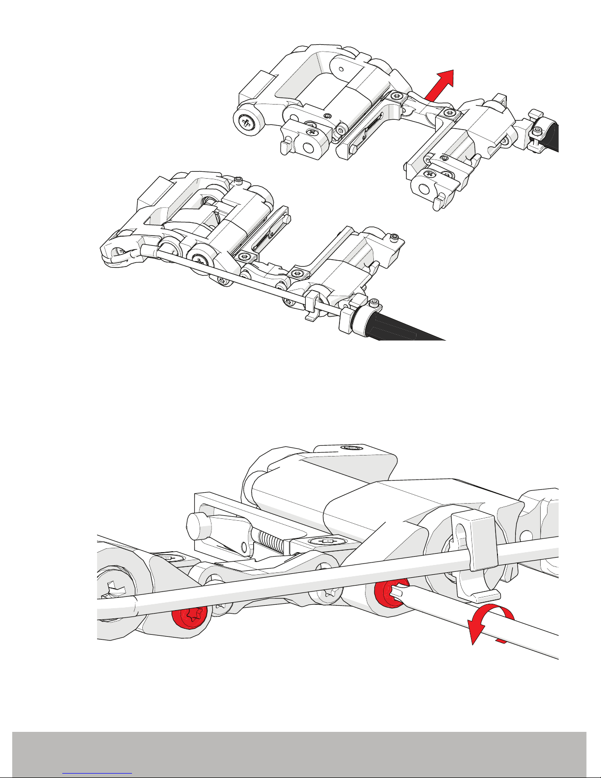
1. Loosen the crossbar retaining screws (Fig. 36).
Fig. 35 - Small diameter scanning
Fig. 36 - Loosen crossbar retaining screws
Page 20
PAGE 15
DJ0050 Rev 03.1
2. Separate the two scanner sections (Fig. 37).
4.3. Installing Wedges
1. If present, remove chain assemblies from the scanner.
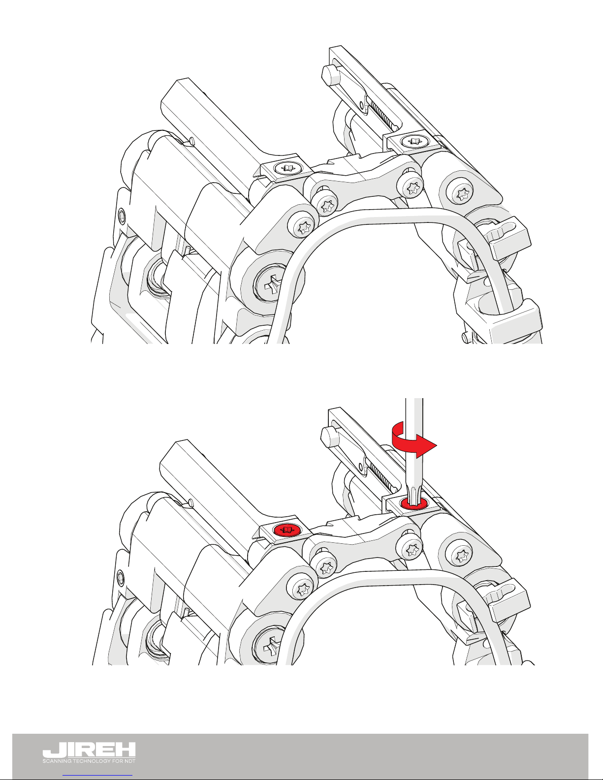
2. Loosen the pivot adjustment screws (Fig. 38)
Fig. 37 - Separate scanner
Fig. 38 - Loosen pivot adjustment screws
Page 21
PAGE 16
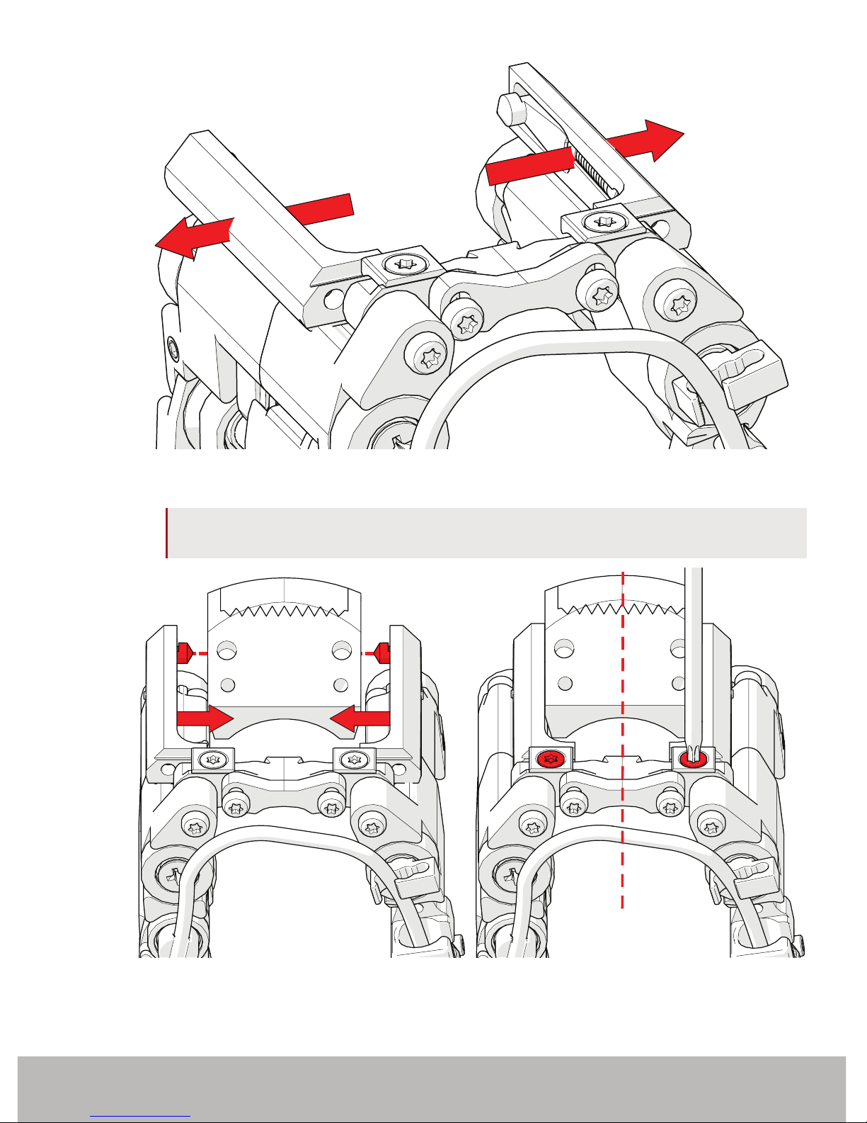
3. Fold the scanner as illustrated (Fig. 39).
4. Loosen the probe holder adjustment screws 1/8
th
of a turn to relieve clamp
pressure (Fig. 40).
Fig. 39 - Fold scanner
Fig. 40 - Loosen probe holder adjustment screws
Page 22
PAGE 17
DJ0050 Rev 03.1
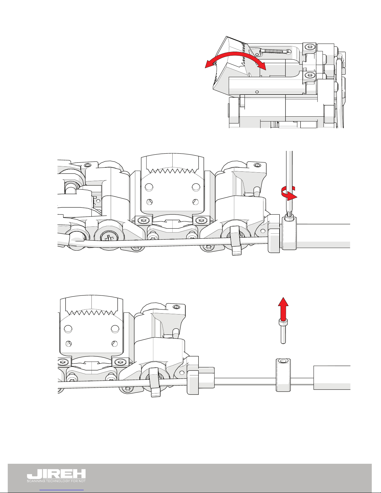
5. Slide the probe holder arms out, without removing them (Fig. 41).
NOTE: It is not necessary to remove the probe holder arms. Be sure to only loosen
and slide the arms outward.
6. Slide the probe holder arms around the wedge. Line up the pivot holes of the
wedge with the probe holder arm pivot buttons (Fig. 42).
Fig. 41 - Loosen probe holder adjustment screws
Fig. 42 - Install wedge Fig. 43 - Centre wedge
Page 23
PAGE 18
7. Align the wedge in the centre of the
probe holder arms (Fig. 43). Tighten
the probe holder adjustment screws
while ensuring they arms are not
pinching the wedge too tightly
restricting wedge pivoting (Fig. 44).
4.4. Sleeve Setup
1. Remove the sleeve clamp screw (Fig. 45) using the supplied Torx® driver
(Fig. 1).
2. Slide the protective sleeve and the sleeve clamp from the sleeve clamp bracket
(Fig. 46). Remove the sleeve and sleeve clamp from the (if applicable) encoder
cable, irrigation hose and encoder cable.
Fig. 44 - Ensure wedge pivoting
Fig. 45 - Remove sleeve clamp screw
Fig. 46 - Remove sleeve, sleeve camp and sleeve clamp screw
Page 24
PAGE 19
DJ0050 Rev 03.1
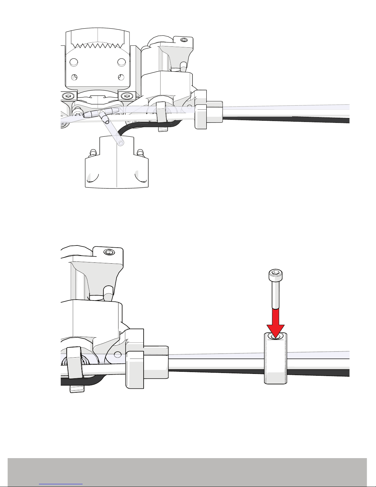
3. Place the encoder cable, irrigation hose and encoder cable in the cable
management clip and run the cable/tube bundle through the sleeve clamp
bracket (Fig. 47).
4. Place the sleeve clamp around the cable and hoses, loosely screw in the
sleeve clamp screw (Fig. 48).
Fig. 47 - Position cables and hose
Fig. 48 - Replace sleeve clamp screw
Page 25
PAGE 20
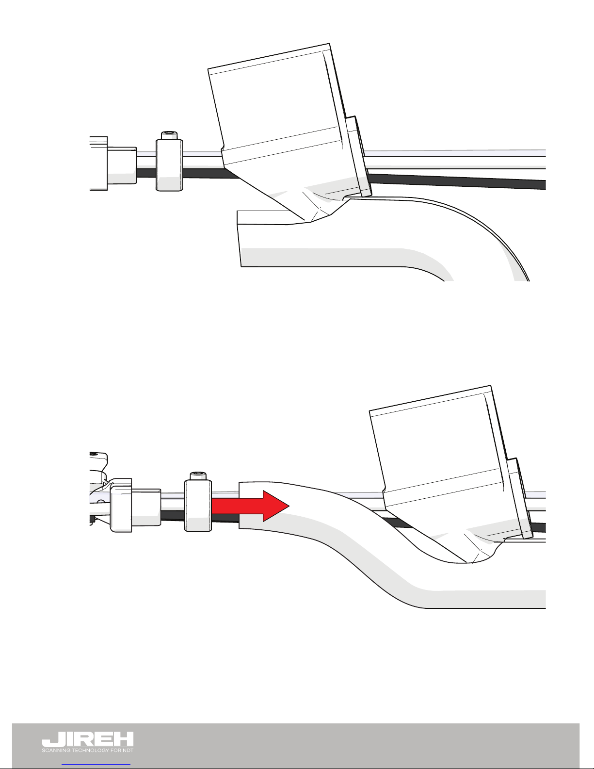
5. Use the loom installation tool to install the protective sleeving over the cable/
tube bundle (Fig. 49).
6. Begin at the scanner end, wrap the tool around the cables with the shoe
pointing away from the scanner. Use the shoe of the loom to open the sleeving
and begin wrapping the open sleeve around the cables (Fig. 49).
7. Once an amount of the sleeving has been installed around the cables, slide the
sleeve clamp around the sleeving (Fig. 50).
Fig. 49 - Loom installation tool
Fig. 50 - Slide the sleeve clamp around sleeving
Page 26
PAGE 21
DJ0050 Rev 03.1
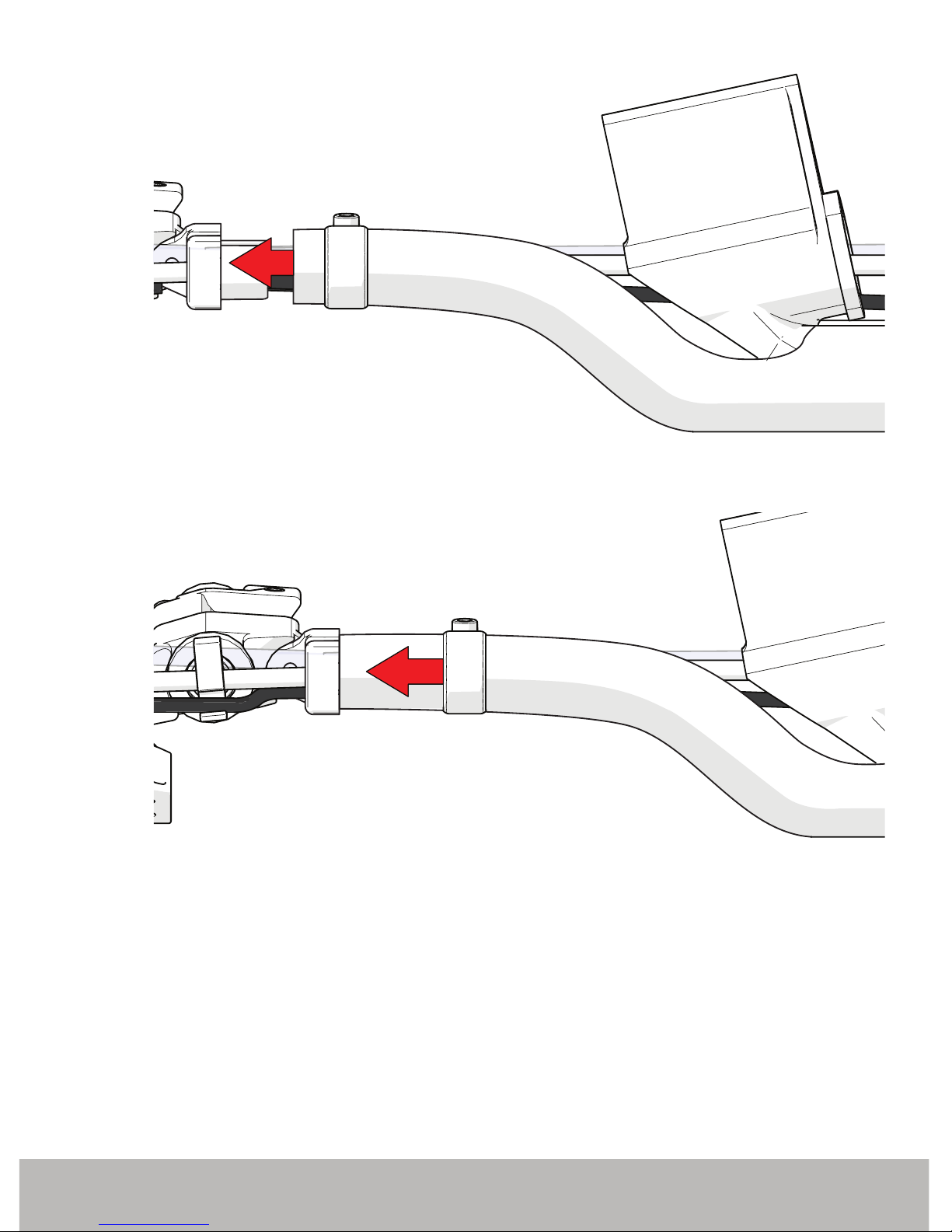
8. Bring the sleeving around the sleeve clamp bracket (Fig. 51).
9. Slide the sleeve clamp over the sleeve clamp bracket and the protective sleeve
(Fig. 52).
Fig. 51 - Position around sleeve clamp bracket
Fig. 52 - Place sleeve clamp around sleeving and sleeve clamp bracket
Page 27
PAGE 22
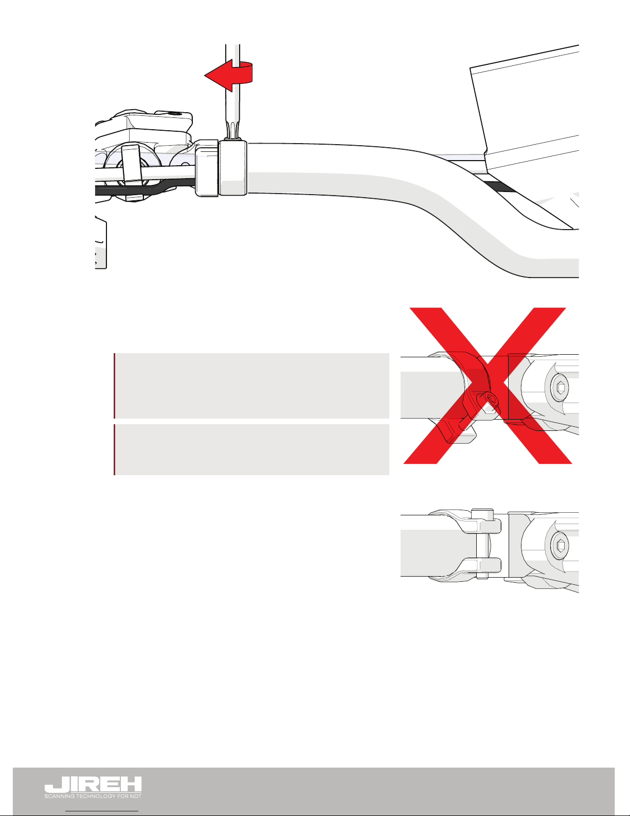
10. Tighten the sleeve clamp screw pinching the
sleeve in place with the sleeve clamp bracket
(Fig. 53).
TIP: Ensure the sleeve clamp is oriented
correctly (Fig. 55) and the sleeve clamp
screw will not protrude lower than the
scanner wheels (Fig. 54).
NOTE: Do not over tighten the sleeve clamp
screw as this may cause the screw to
break.
11. Continue inserting the remaining cable and
hoses into the protective sleeve using the loom
installation tool.
12. Repeat this sleeving process with scanners
opposite side.
Fig. 53 - Tighten sleeve clamp screw
Fig. 54 - Incorrect clamp alignment
Fig. 55 - Correct clamp alignment
Page 28
PAGE 23
DJ0050 Rev 03.1
4.5. Setting Wedge Spacing
1. If present, remove all chain assemblies from the scanner.
2. Ensure wedges are installed (see Installing Wedges on page 15).
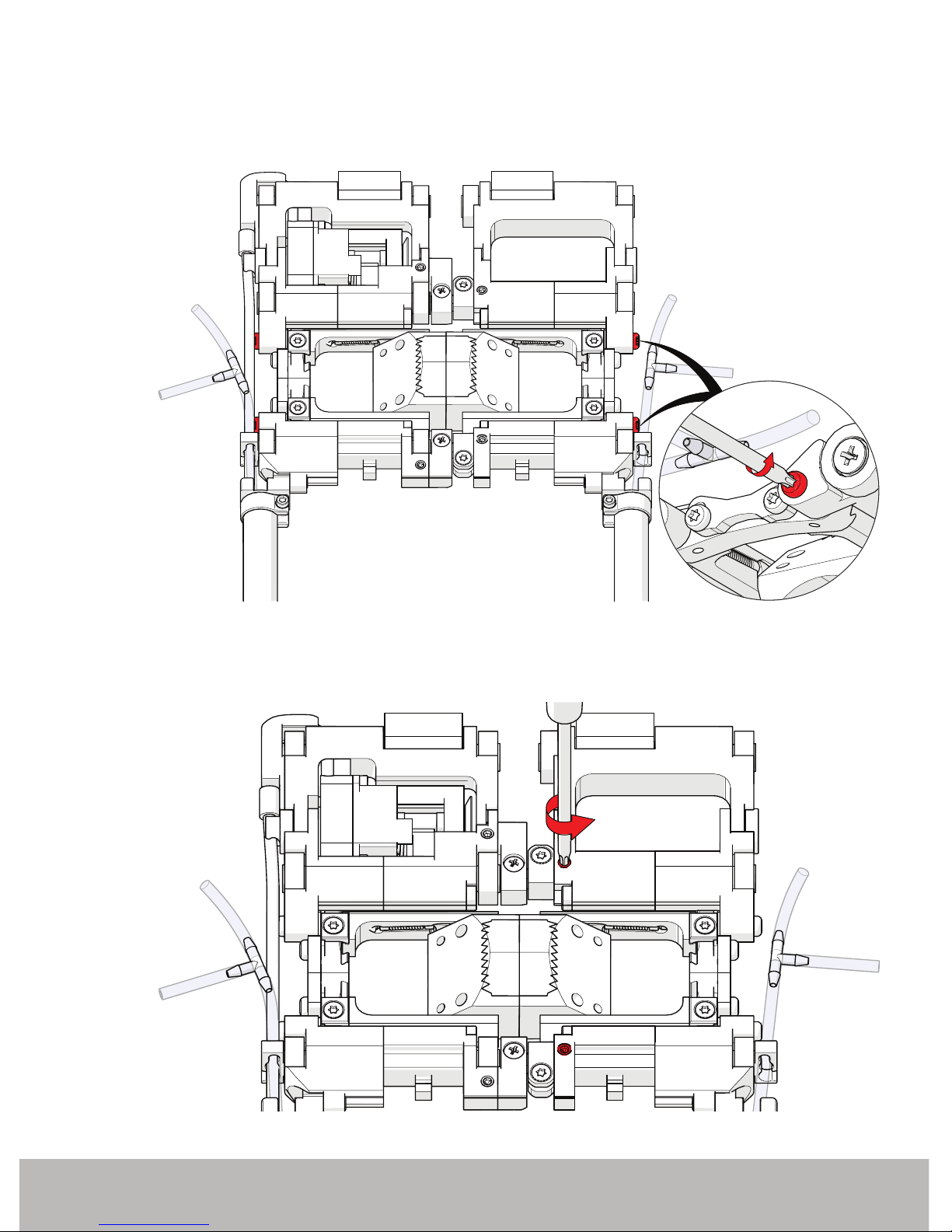
3. Use the supplied Torx® driver (Fig. 1), loosen the four pivot adjustment screws
(Fig. 56) and press the scanner against a at surface straightening out the
scanner.
Fig. 56 - Loosen the pivot adjustment screws
Fig. 57 - Loosen the crossbar clamp screws
Page 29
PAGE 24
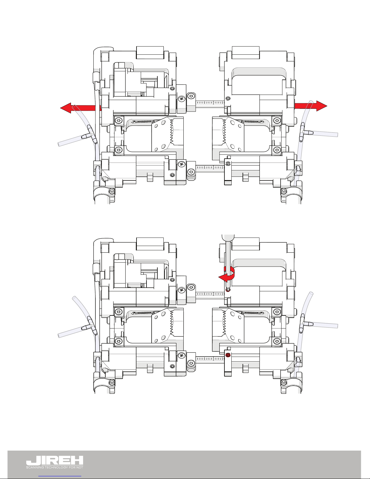
4. Loosen the two crossbar clamp screws located on the dual side of the scanner
(Fig. 57).
5. Slide the two sides of the scanner apart, use the measurements of the
crossbar to determine desired spacing (Fig. 58).
6. Ensure alignment of the scanner using the measurements on the crossbar and
tighten the crossbar clamp screws (Fig. 59).
Fig. 58 - Slide apart to required spacing
Fig. 59 - Tighten crossbar clamp screws
Page 30
PAGE 25
DJ0050 Rev 03.1
4.5.1. Wedge Separation Indicators
The wedge separation indicators allow precise probe/wedge spacing. The
crossbar graduations indicate millimeter measurement. To utilize the wedge
separation indicators, follow these steps:
1. If present, remove all chain assemblies from the scanner.
2. Ensure wedges are installed (see Installing Wedges on page 15).
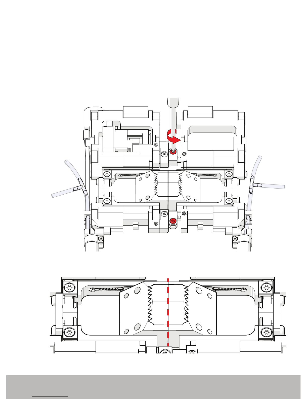
3. Use the supplied Torx® driver (Fig. 1) to loosen the four pivot adjustment
screws (Fig. 56), press the scanner against a at surface to straighten.
4. Use the supplied Torx® driver to loosen the both wedge separation
indicator clamp screws (Fig. 60).
5. Slide the scanner together until the wedges make contact (Fig. 61).
Fig. 60 - Loosen the pivot adjustment screws
Fig. 61 - Ensure wedge contact
Page 31
PAGE 26
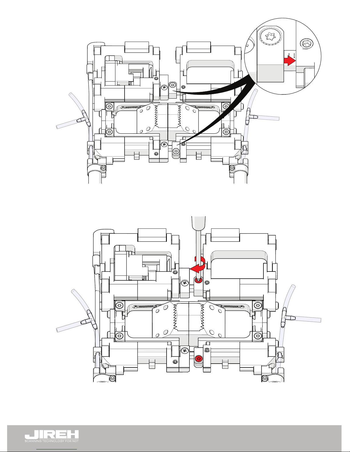
6. Ensure the wedges continue to touch while sliding the wedge separation
indicators to contact the dual side of the scanner (Fig. 62).
7. Tighten the wedge separation indicator clamp screws (Fig. 63).
Fig. 62 - Position wedge separation indicators
Fig. 63 - Tighten wedge separation indicator clamp screws
Page 32
PAGE 27
DJ0050 Rev 03.1
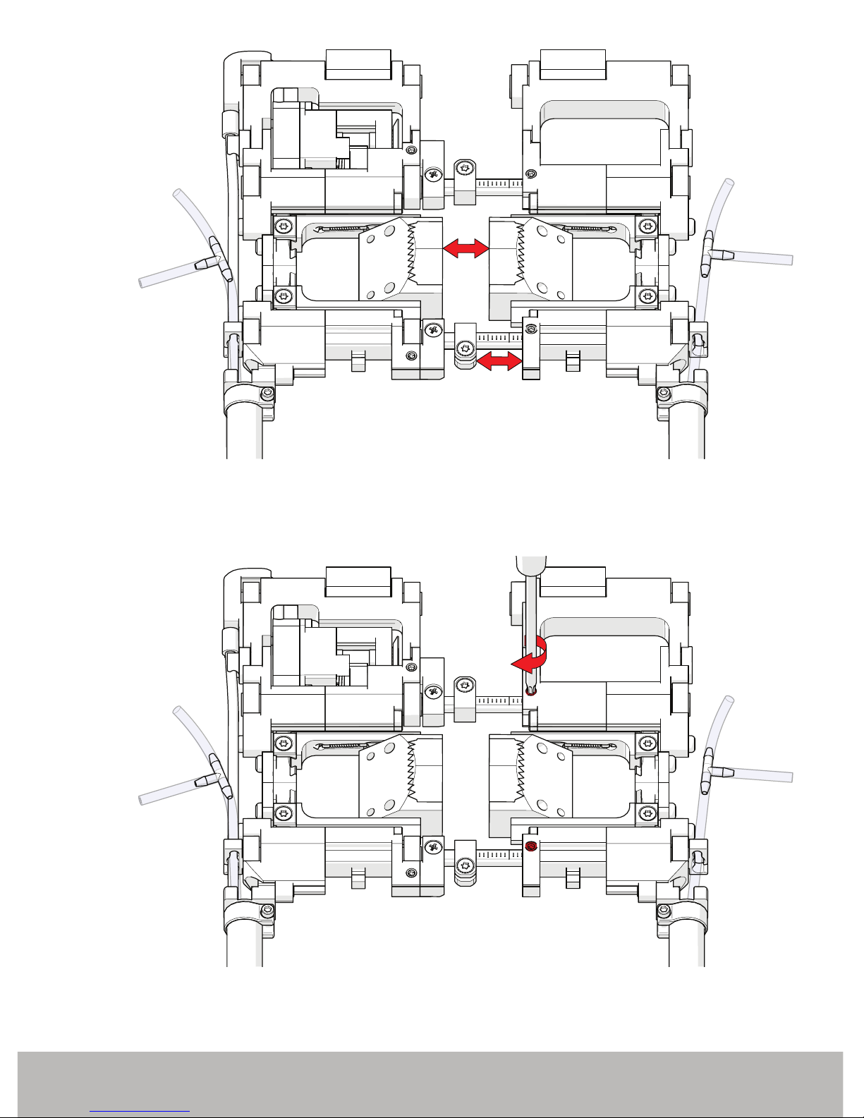
8. Slide the two sides apart until desired wedge separation is achieved
(Fig. 64). Use the graduations on the crossbar for precise positioning. The
graduations indicate millimeter measurement.
9. Tighten both crossbar clamp screws (Fig. 65).
X
X
Fig. 64 - Set precise wedge separation
Fig. 65 - Tighten crossbar clamp screws
Page 33
PAGE 28
4.6. Circ-it Setup (Single-Sided Access)
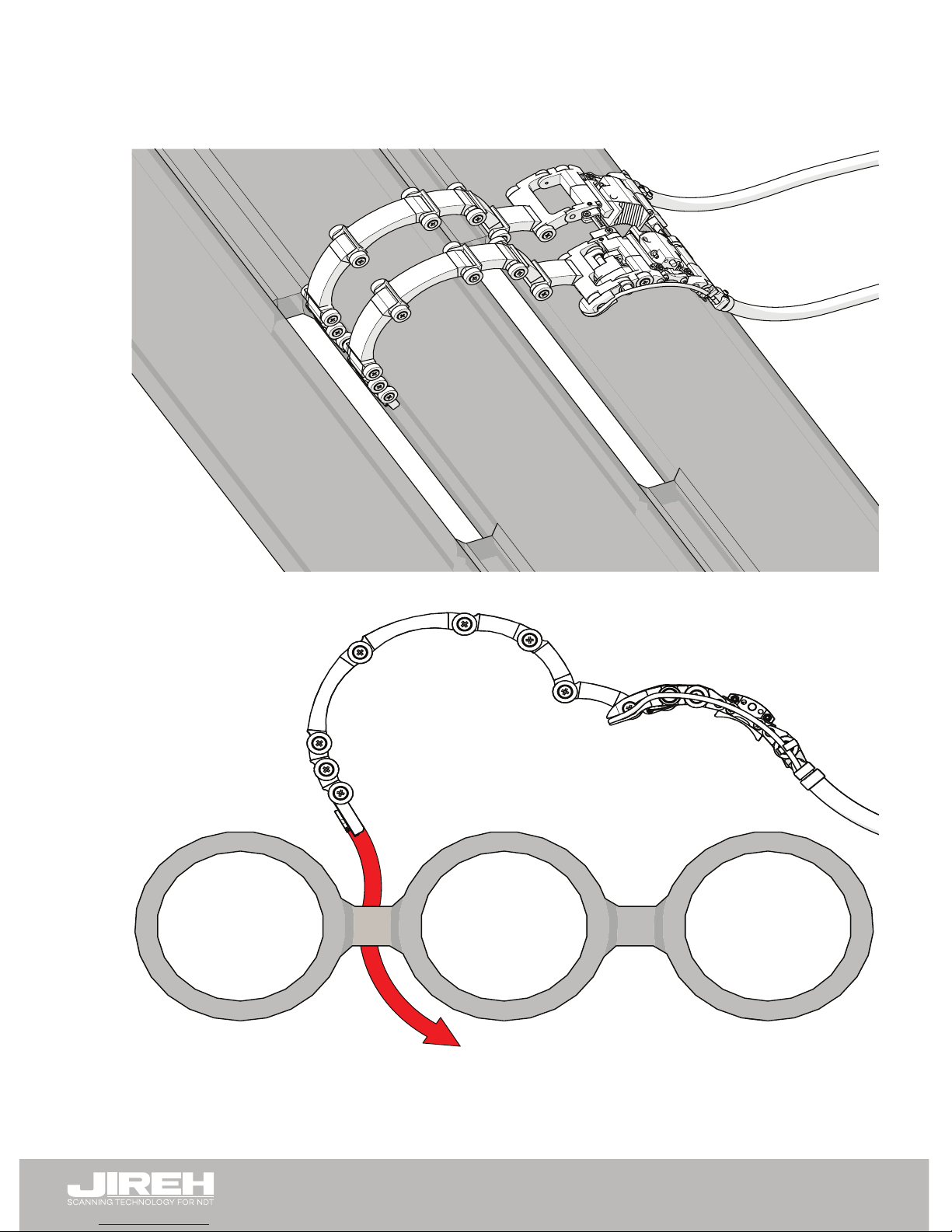
To congure the CIRC-IT for applications when access to the pipe/tube is single-
sided, use the supplied chain retrieval tool (Fig. 3) and follow these steps:
1. Shape the links and wheels to a slight curve not including the scanner body
(Fig. 66) and (Fig. 67).
Fig. 66 - Position links as illustrated
Fig. 67 - Position links as illustrated
Page 34
PAGE 29
DJ0050 Rev 03.1
2.
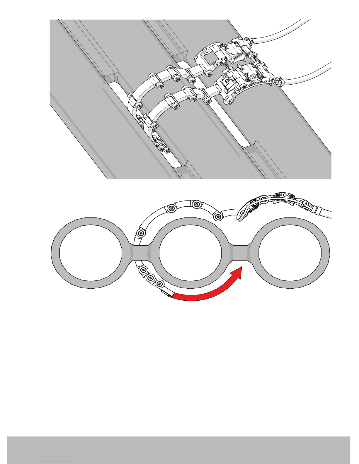
3. While guiding the links around the pipe/tube, pivot the scanner body as
required (Fig. 68) and (Fig. 69).
Fig. 68 - Pivot scanner while rotating links around pipe/tube
Fig. 69 - Pivot scanner while rotating links around pipe/tube
Page 35
PAGE 30
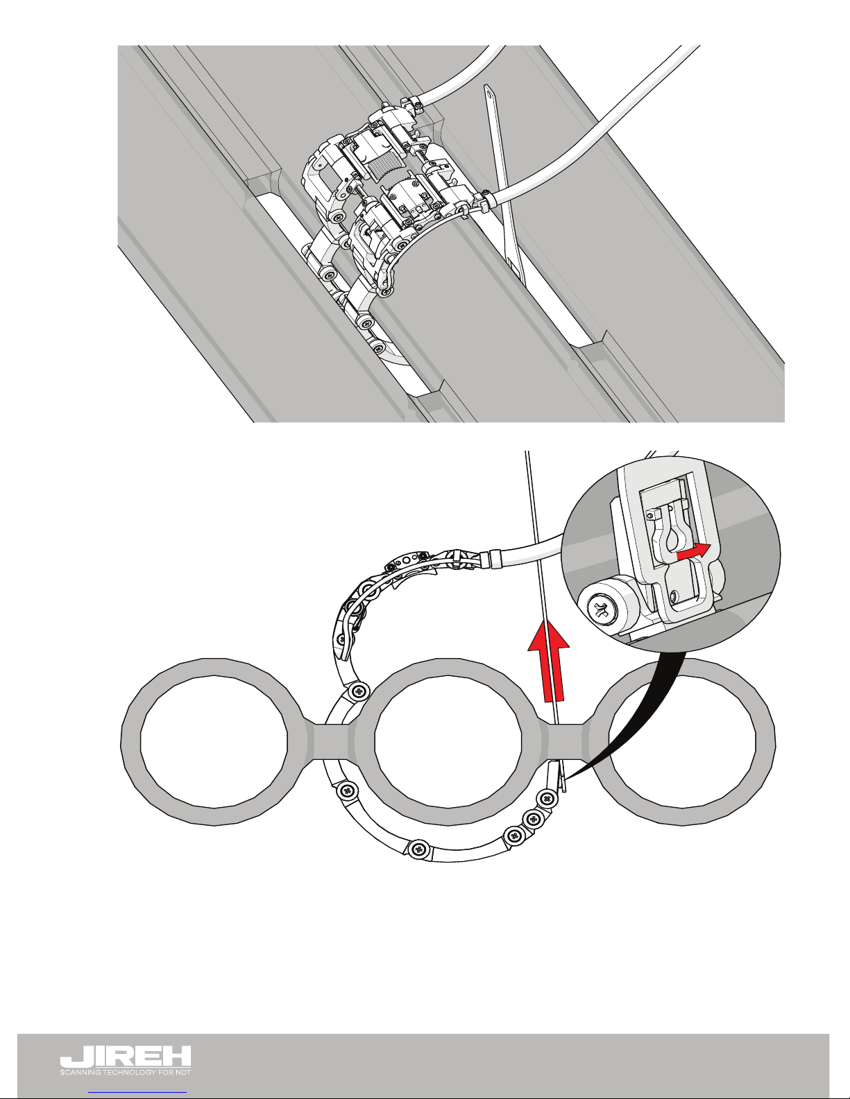
4. The chain retrieval tool is used to pull the latch through a tight space. The chain
retrieval tool is designed to ip open the latch’s tab, allowing the chain retrieval
tool to hook the latch tab (Fig. 70) and (Fig. 71). The chain retrieval tool can also
be used if available space to retrieve the latch is too small and the tab can not
be opened.
Fig. 70 - Use chain retrieval tool to access latch
Fig. 71 - Use chain retrieval tool to access latch
Page 36
PAGE 31
DJ0050 Rev 03.1
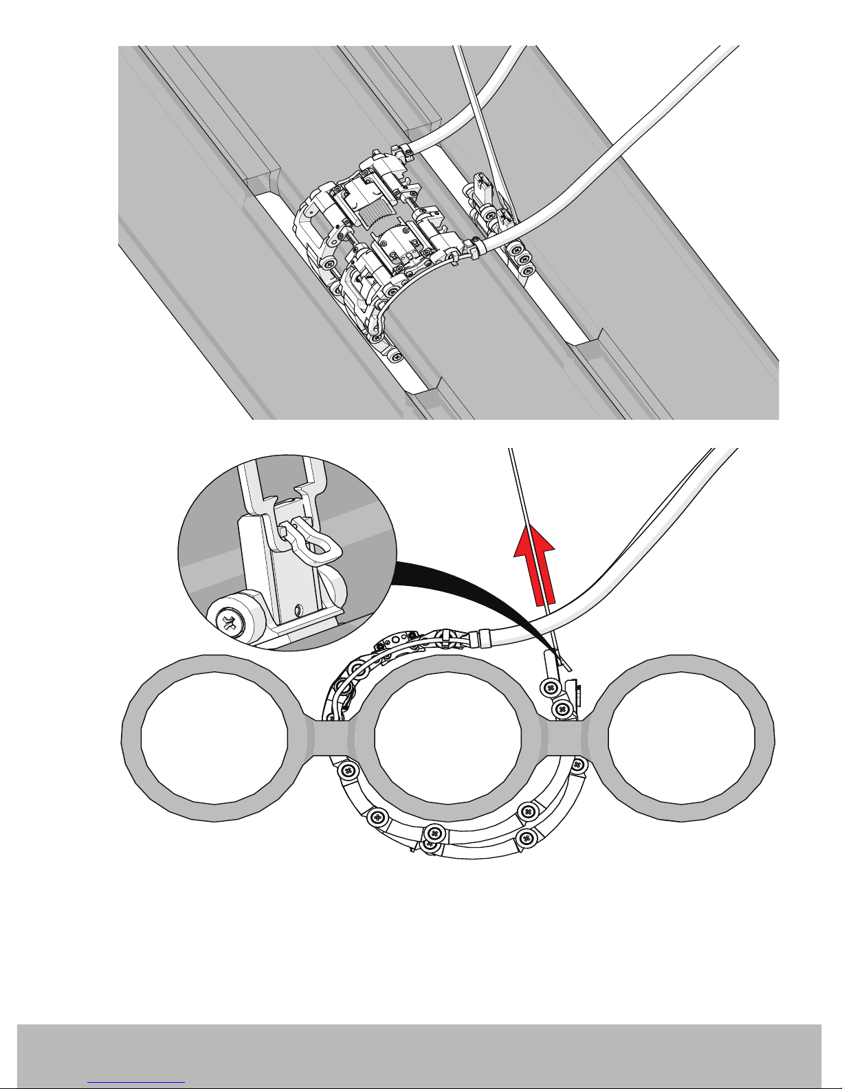
5. Bring the latch around the scan surface (Fig. 72) and (Fig. 73).
Fig. 72 - Bring latch towards the latch hook
Fig. 73 - Bring latch towards the latch hook
Page 37
PAGE 32
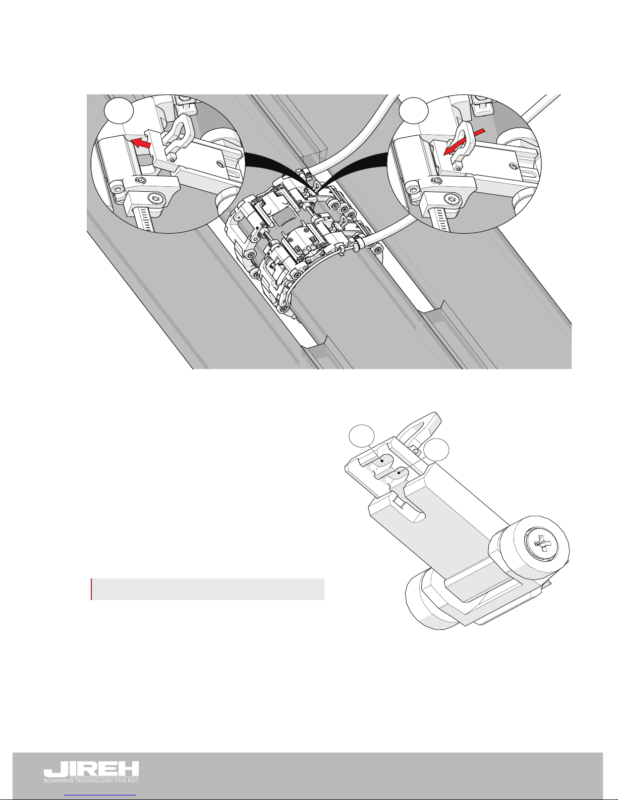
6. To complete the installation of the scanner, pull the latch over the latch hook of
the scanner. Bring the latch down and hook the scanner’s latch hook. (see Latch
Connection on page 32).
4.7. Latch Connection
The short and long latch are the nal
connection point of the scanner. Either
of these latches may be used depending
on the size of the pipe or tube to being
scanned (see Circ-it Conguration Chart
on page 4). To achieve optimal
performance, use the latch connection
that offers the tightest t.
TIP: This example displays a long latch.
1 2
Fig. 74 - Tighten wedge separation indicator clamp screws
2
1
Fig. 75 - Two latching points
Page 38
PAGE 33
DJ0050 Rev 03.1
4.8. Link Connection
A variety of links are included with the CIRC-IT. To connect the links, see the
following steps:
TIP: These connection instructions also apply to wheel blocks and latches.
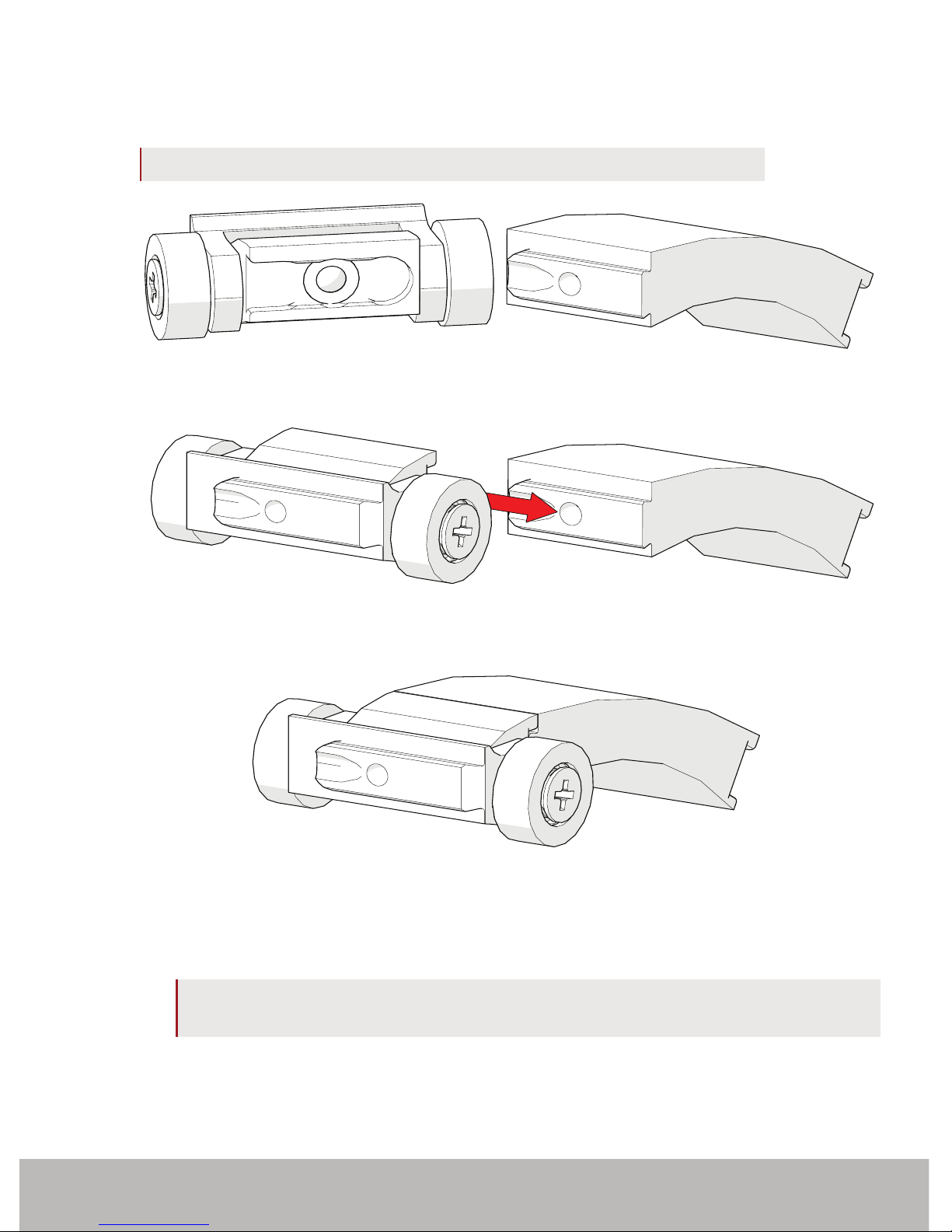
1. Note the different ends of the links which will provide the connection (Fig. 76).
2. Align the two links horizontally and slide them together (Fig. 77).
3. When the links are ush and you feel/hear the spring plunger click, the links are
properly connected (Fig. 78).
4. To disconnect links and wheel blocks, reverse these steps.
NOTE: Alternate wheel blocks and links ensuring links are always separated by a
wheel block (see Correct Link Conguration on page 34).
Fig. 76 - Link ends differ
Fig. 77 - Slide links together
Fig. 78 - Connected link and wheel block
Page 39
PAGE 34
4.8.1. Correct Link Conguration
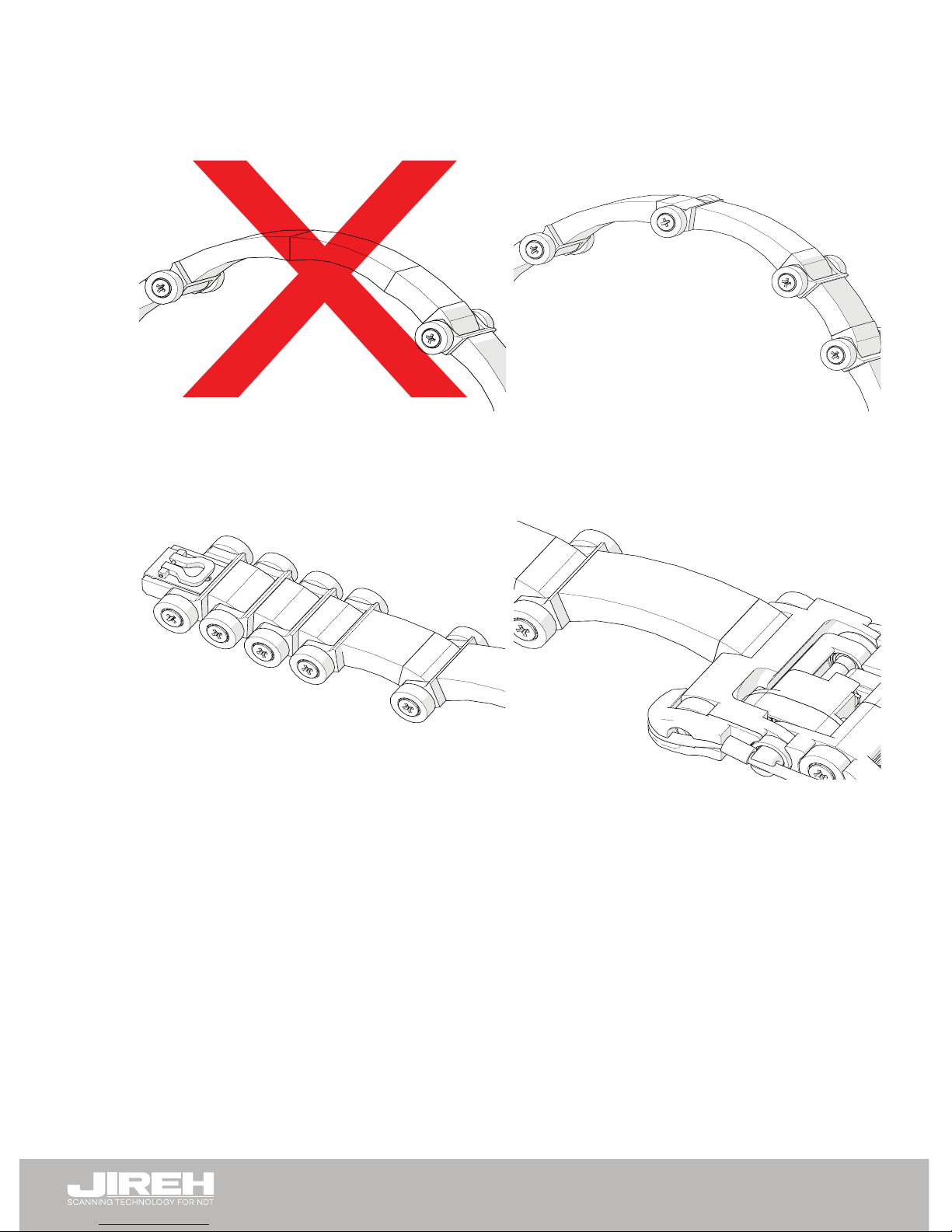
Proper link conguration and setup is necessary to achieve optimal scanner
performance. Ensure the following points are implemented:
1. Do not connect a link of any size directly to another link (Fig. 79).
2. Alternate wheel blocks and links ensuring links are always separated by a
wheel block (Fig. 80).
3. When the number of wheel blocks required (according to the chain conguration
chart) is more than the required links, connect the additional wheel blocks to the
latch end of the chain conguration (Fig. 81).
4. A wheel block is not required when connecting the scanner’s link mount
(Fig. 15-L) to the chain conguration (Fig. 82).
x
Fig. 79 - Incorrect link connection Fig. 80 - Alternate wheel blocks and links
Fig. 81 - Connect wheel blocks to latch Fig. 82 - No wheel block between scanner and link
Page 40

PAGE 35
DJ0050 Rev 03.1
CHAPTER 5
SERVICE AND REPAIR
5.1. Troubleshooting
Problem Possible Cause Solution
1. Chain is too
loose/tight.
Incorrect number or
combination of links.
Refer to the CIRC-IT setup chart (see Circ-it
Conguration Chart on page 4) to assemble
the correct conguration for the size of pipe/
tube being scanned.
Incorrect latch setting.
Ensure the latch is set using the tightest notch
possible (see Latch Connection on page 32).
Incorrect latch used. When scanning pipe/tube with an OD less
than 50.8 mm (2 in), the short latch must be
used. When scanning pipe/tube with an OD
greater than 50.8 mm (2 in), the long latch
must be used (see Circ-it Conguration Chart on
page 4).
2. Insufcient
probe contact.
Scanner not set
properly.
Recongure the scanner as per instructions
(see Setup of Circ-it on a Pipe or Tube on page
9).
Pivot adjustment
screws were not
adequately tightened.
Recongure the scanner as per instructions
(see Setup of Circ-it on a Pipe or Tube on page
9) and ensure pivot adjustment screws
are tight.
Setup tab not raised. Ensure the setup tab has been raised and
its screws tightened. (see Loosen the screws
of the setup tab on both sides of the scanner (Fig.
29). on page 13) There is a setup tab on
each side of the scanner.
Cables and/or hoses
are routed incorrectly.
Ensure the cables and hoses are not
impeding proper scanner operation.
3. Clearance
issues when
scanning
small
diameters.
Remove encoder
cable guard.
(see Setup on diameters smaller than 31.75 mm
(1.25 in) on page 13)
5.2. Technical Support
For technical support contact Jireh Industries (see Jireh Industries Ltd. on page i).
Page 41

PAGE 36
5.3. Disposal
WEEE Directive
In accordance with European Directive on Waste Electrical and
Electronic Equipment (WEEE), this symbol indicated that the
product must not be disposed of as unsorted municipal waste,
but should be collected separately. Refer to Jireh Industries for
return and/or collection systems available in your country.
Page 42
PAGE 37
DJ0050 Rev 03.1
CHAPTER 6
SPARE PARTS
To order accessories or replacement parts for your CIRC-IT system.
(contact Jireh Industries Ltd. on page i)
NOTE: These drawings are for parts order. This is not a list of kit contents.
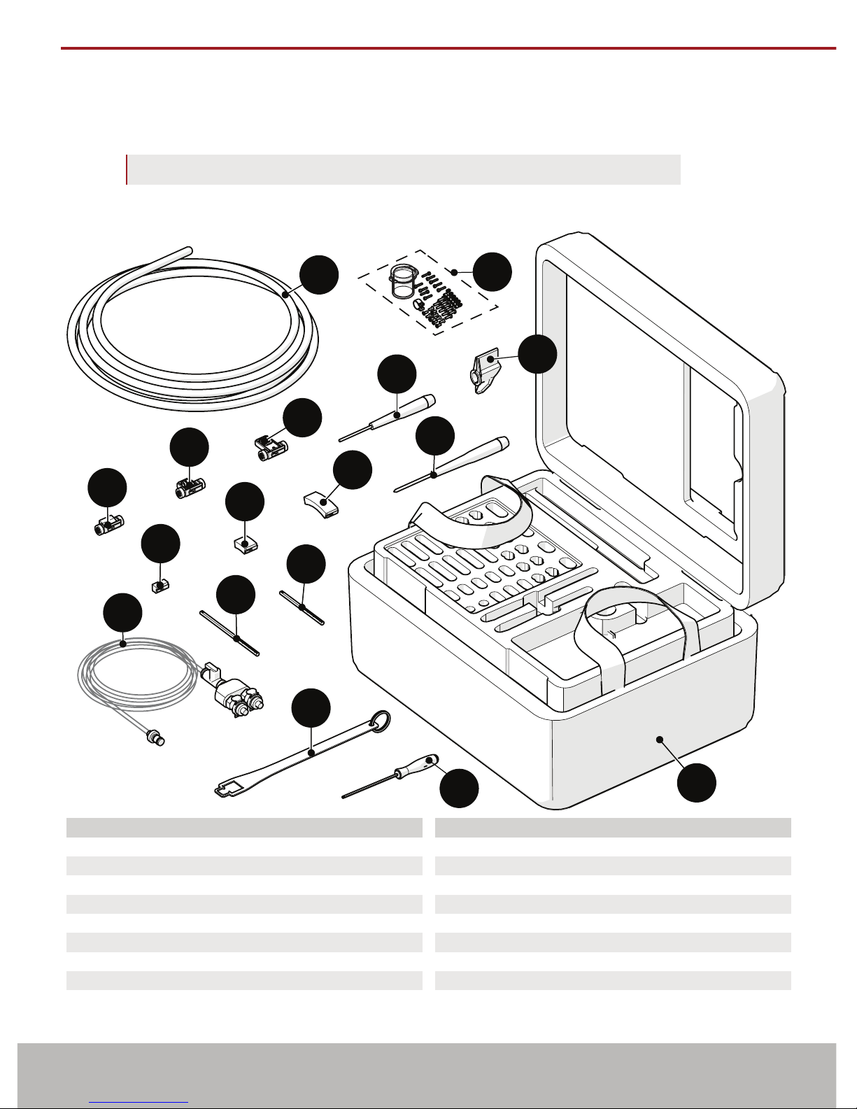
6.1. Circ-it Kit Components
2
12
17
1
6
4
3
10
9
5
8
11
13
14
15
16
BOM ID Part # Description
1 CTL-SP036-1.500
2 DJG002 Circ-it Spare Fasteners
Sleeve
3 DJS006 Wheel Block
4 DJS008 Short Latch
5 DJS012 Long Latch
6 EA303 Torx® Driver
7 EA302 Loom Installation Tool
9
EA307 Phillips Driver
BOM ID Part # Description
8 DJS013-0.735 Short Link
10
DJS013-1.125 Medium Link
11
DJS013-1.815 Long Link
12
13
14
DJS020 Irrigation Splitter
15 DJS018 Chain Retrieval Tool
16
DJA002 Circ-it Case17
EA476 2 mm Hex Driver
7
DJ0034-094 Crossbar
DJ0034-069 Crossbar
Fig. 83 - Circ-it kit components
Page 43
PAGE 38
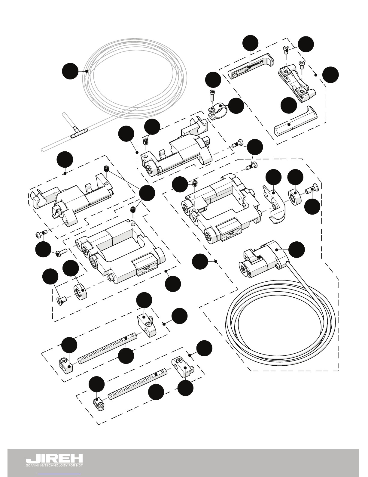
6.2. Circ-it Scanner
1
4
2
9
3
7
5
23
6
8
25
10
11
18
14
17
13
12
1
4
5
10
19
13
11
15
20
22
21
21
20
24
16 13
17
15
Fig. 84 - Circ-it scanner parts
Page 44

PAGE 39
DJ0050 Rev 03.1
BOM ID Part # Description
1 DJS017 Irrigation Tube
2 DJS001-R Probe Holder Arm, Right
3 MA126 Probe Holder Adjustment Screw
4 DJS002 Probe Holder
5 DJS001-L Probe Holder Arm, Left
6 MD046-008
7 DJ0013 Sleeve Clamp
8 DJS007 Primary Swing Arm, Right
9 MA155 Crossbar Clamp Screw
10 DJS010 Secondary Swing Arm, Left
11 MA125 Pivot Adjustment Screw
12 MD308-005
13 DGS006 Wheel
14 DJS009 Encoderless Link
15 MA054 Crossbar Retaining Screw
16 DJ0063 Encoder Cable Guard
17 MD028-008 FHCS, M3 x 0.5 x 8 mm, SST
Sleeve Clamp Screw
FHMS, M3 x 0.5 x 5 mm, Phillips, SST
18 DJS023-X Encoded Link
(see Encoder Connector Type)
19 DJS019-X Circ-it Encoder (see Encoder Connector Type)
20 DJS027 Wedge Separation Indicator
21 DJ0034-X Crossbar
(see Crossbars)
22 DJS026-R Crossbar Clamp Bracket, Right
23 DJS011-R Crossbar Assembly, Right
24 DJS026-L Crossbar Clamp Bracket, Left
25 DJS011-L Crossbar Assembly, Left
Fig. 85 - Circ-it scanner parts (continued)
Page 45
PAGE 40
6.2.1. Encoder Connector Type
NOTE: Additional encoder connector styles available.
(contact Jireh Industries Ltd. on page i)
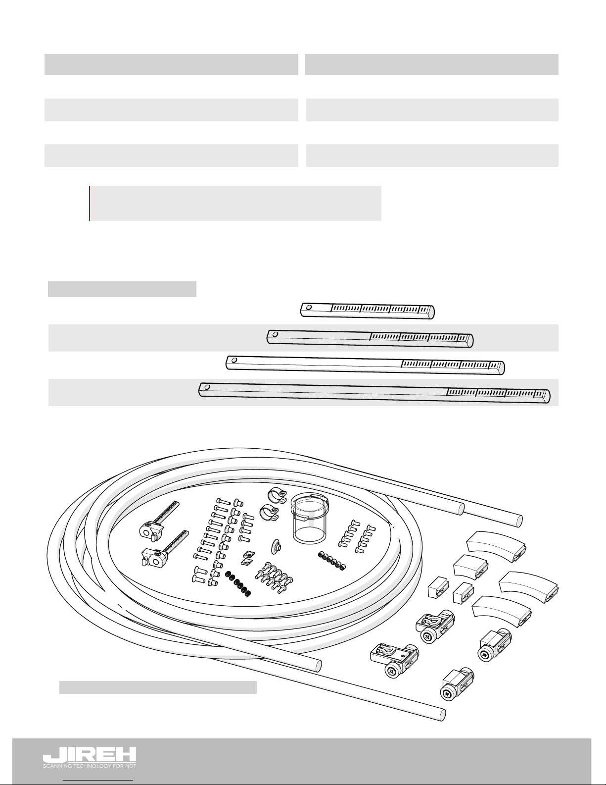
6.3. Accessories
6.3.1. Crossbars
6.3.2. Circ-it Spare Parts Kit
A
B
C
D
E
F
G
H
Arm Style
Short
Long
Standard, Drop
Short, Drop
Long, Drop
Standard,
Extra-Drop
Short, Extra-Drop
Standard
PH0089
PH0099
PH0093
I
J
Extra-Short
Extra-Short, Drop
PH0159
PH0161
PH0092
PH0094
PH0095
PH0096
PH0090
Part #
Arm Style Part #
Part #
BG0038-15
BG0038-05
15
cm (5.91 in)
5
cm (1.97 in)
BG0038-35
BG0038-25
35
cm (13.78 in)
25
cm (9.84 in)
BG0038-55
BG0038-45
55
cm (21.65 in)
45
cm (17.72 in)
Length Part #
BG0038-20
BG0038-10
20
cm (7.87 in)
10
cm (3.94 in)
BG0038-40
BG0038-30
40
cm (15.75 in)
30
cm (11.81 in)
BG0038-50
50
cm (19.69 in)
Length
01
02
03
04
Pivot Hole Size
5.0 mm (0.20 in)
2.7
mm (0.11 in)
9.5
mm (0.38 in)
8.0
mm (0.32 in)
Olympus TOFD
Sonatest DAAH PA
-
Olympus PA
06
07
08
09
2.3 mm (0.09 in)
Conical Head
5
mm (0.20 in) Internal
3.0 mm (0.12 in)
-
-
Zetec PA/TOFD
-
Wedge Type
Pivot Hole Size Wedge Type
Large
Standard
PHS048
8.3
cm (3.26 in)
12.2 cm (4.79 in)
LengthYoke Style
Yoke Style Part #
PHS047
Part #Length
S
W
S
W
Yoke Style
Wide
Standard
PHS027
PHS017
Part #
6.3 cm (2.47 in)
Length
7.9 cm (3.06 in)
Length
Yoke Style Part #
B
C
Connector
Type
Olympus - Focus LT / Zetec Z-Scan
Olympus - OmniScan MX / Zetec - ZIRCON, TOPAZ
Company/Instrument
G
M
Connector
Type
GE - USM Vision
Sonotron - Isonic
D
F
TD - Focus Scan, Handy Scan, Pocket Scan
Olympus - OmniScan MX2, OmniScan SX
U
Sonatest - VEO, PRISMA
Company/Instrument
V
Pragma PAUT 16/128, PragmaLite / Pragma UT400
Fig. 86 - Encoder connectors
Part #
DJ0034-069
DJ0034-044
69 mm
(2.7 in)
44 mm (1.7 in)
DJ0034-119
DJ0034-094
119 mm
(4.7 in)
94 mm (3.7 in)
Length
Fig. 87 - Crossbars
Part # Description
DJG003 Circ-it Spare Parts Kit
Fig. 88 - Circ-it spare parts kit
Page 46

PAGE 41
DJ0050 Rev 03.1
CHAPTER 7
LIMITED WARRANTY
WARRANTY COVERAGE
Jireh Industries warranty obligations are limited to the terms set forth below: Jireh
Industries Ltd. (“Jireh”) warrants this hardware product against defects in materials and
workmanship for a period of THREE (3) YEARS from the original date of purchase. If
a defect exists, at its option Jireh will (1) repair the product at no charge, using new
or refurbished replacement parts, (2) exchange the product with a product that is new
or which has been manufactured from new or serviceable used parts and is at least
functionally equivalent to the original product, or (3) refund the purchase price of the
product. A replacement product/part assumes the remaining warranty of the original
product or ninety (90) days from the date of replacement or repair, whichever provides
longer coverage for you. When a product or part is exchanged, any replacement item
becomes your property and the replaced item becomes Jireh’s property. When a refund
is given, your product becomes Jireh’s property.
OBTAINING WARRANTY SERVICE
To utilize Jireh’s warranty service you must ship the product, at your expense, to and
from Jireh Industries. Before you deliver your product for warranty service you must
phone Jireh and obtain an RMA number. This number will be used to process and track
your product. Jireh is not responsible for any damage incurred during transit.
EXCLUSIONS AND LIMITATIONS
This Limited Warranty applies only to hardware products manufactured by or for
Jireh Industries. This warranty does not apply: (a) to damage caused by accident,
abuse, misuse, misapplication, or non-Jireh products; (b) to damage caused by
service (including upgrades and expansions) performed by anyone who is not a Jireh
Authorized Service Provider; (c) to a product or a part that has been modied without
the written permission of Jireh.
Jireh Industries Ltd.
53158 Range Rd 224
Ardrossan, AB T8E 2K4
Canada
Phone: 780-922-4534
Fax: 780-922-5766
jireh-industries.com
Page 47

PAGE 42
All brands are trademarks or registered trademarks of their respective owners and third party
entities.
Changes or modications to this unit or accessories, not expressly approved by the party
responsible for compliance could void the user’s authority to operate the equipment.
All specications are subject to change without notice.
© 2016 Jireh Industries Ltd.
Page 48

Jireh Industries Ltd.
53158 Range Road 224
Ardrossan, Alberta
Canada
T8E 2k4
780-922-4534
jireh-industries.com
 Loading...