

Page 1

Do Žlábku 733, 514 01 Jilemnice
Subject: MTP Technical documentation Page No./No. of pages: 1/20
Approved by: Date: 12. 2. 2018
TECHNICAL DOCUMENTATION FOR USERS OF AIR HEATERS
MTP, MTPAL, MTP-V
Contents:
Page: 2 Warranty card
3 Certificate of product quality and completeness. (Unit test report)
5 Technical conditions
11 Installation, operating and maintenance instructions
17 Related documents
17 List of warranty and post-warranty repair services
18 Optional equipment
Warranty card
Page 2

Do Žlábku 733, 514 01 Jilemnice
Subject: MTP Technical documentation Page No./No. of pages: 2/20
The manufacturer is responsible for defects in the product that have been proven to be
incurred in the warranty period by a faulty construction or faulty design.
The warranty does not apply to cases where the user
- makes adjustments or changes to the product
- violently breaks the product
- connects the product with incorrect values (e.g. lower amount of air, higher heat output)
- chooses a different working environment for the product than that recommended by the
manufacturer in the enclosed information
- does not comply with the technical conditions supplied with the product
Warranty period:
24 months from the date of delivery of the product, subject to all of the above stated
conditions (instructions and recommendations of the manufacturer).
The manufacturer reserves the following as a warranty condition - commissioning and
checking by a qualified worker of an assembly company and completing and signing the
“Heat exchanger unit commissioning protocol”, which is an integral part of this warranty
card.
If it is contractually agreed in some cases during the sale, the manufacturer reserves
commissioning or checking by their own personnel as a warranty condition.
The warranty can also be contractually conditioned by regular inspections by
manufacturer’s personnel.
Product name: AIR HEATER
Type/design: MTP
Combustion chamber used: BK
Serial number:
Product delivery date confirmed by the Seller:
Product commissioning date confirmed by the Supplier:
___________________________________________________________________________
When you submit a claim, please, provide this warranty card together with the heater
commissioning protocol with confirmed participation of a worker of the manufacturer
during start-up of the equipment and together with the protocol on setting up the burner to
the prescribed values.
The warranty card is invalid without confirmation of product commissioning!
Page 3

Do Žlábku 733, 514 01 Jilemnice
Subject: MTP Technical documentation Page No./No. of pages: 3/20
AIR HEATER COMMISSIONING PROTOCOL
TO BE FILLED IN BY A QUALIFIED WORKER OF THE ASSEMBLY COMPANY
TYPE: MTP Ser. No.:
Compliance with all installation conditions according to this “MTP Technical
documentation” has been checked. Installation instructions (installation, safety distances,
connection of the air-conditioning circuit, smoke flue connection including condensate
drainage, assembly of burner and electrical installation).
In particular, connection of all thermostats has been checked:
T1 (safety) - switches off the burner feed phase
T2 (operational) - switches off the burner
T3 (operational) - switches the fans and ensures their slowdown (cooling down the
heat exchanger chamber) after switching off the unit
The amount of air flowing through the heat exchanger chamber has been checked.
Overall installation (quality, completeness, craftsmanship) has been checked.
For heaters equipped with bypass, the following has been checked:
- control of valve actuators (in particular the direction of rotation)
- no valve position causes overheating of the heat exchanger and thus activation of
the operating thermostat
- there is no excessive condensation
For heaters equipped with a fan, the following has been checked:
- correct direction of rotation of the fan
- correct belt tension, if it is a belt drive
The stated heater has been installed and connected according to the “Technical
documentation” of the manufacturer and is capable of continuous operation.
The commissioning and check has been carried out by:
Name: ................................ signature: .............................. date:.........................
Page 4

Do Žlábku 733, 514 01 Jilemnice
Subject: MTP Technical documentation Page No./No. of pages: 4/20
Certificate
of product quality and completeness
Unit test report
By this certificate the manufacturer confirms that the properties of the product,
name: AIR HEATER
type/design: MTP
serial number: ............................................
basic tech. data: Nominal heat input ........................................ kW
Nominal heat output ..................................... kW
Nominal air flow ............................................ m3/h
External air pressure ...................................... Pa
Nominal electrical input................................. kW
Weight............................................................ kg
Protection IP
Voltage 3x400 V + N + PE 50 Hz
Electric engine used: .....................................
V-belt: ...........................................................
comply with the test regulations:
..................................................................................................
date:
technical control department:
___________________________________________________________________________
production plant director
Ing. Václav Šubrta
Page 5

Do Žlábku 733, 514 01 Jilemnice
Subject: MTP Technical documentation Page No./No. of pages: 5/20
TECHNICAL CONDITIONS
INSTRUCTIONS FOR INSTALLATION, OPERATION
AND MAINTENANCE OF AIR HEATER MTP,
MTPAL, MTP-V
1. Use:
Air heaters using gaseous fuels are used to heat the air for purposes of heating or
ventilation with heating and are designed for separate operation or for installation in airconditioning systems, air-conditioning units and other applications.
2. Function description
The basis of the heaters MTP, MTPAL, MTP-V is a closed air-flue gas exchanger which
consists of a combustion chamber and a tube heat exchanger. The air-conditioning and
combustion circuit of the air heater are therefore separated. The heater heats the air
conveyed by the fan that is or is not part of the heater (depending on the type). The air is
sucked directly from the heated space or via the air-conditioning piping. The air is heated
while circling around the combustion chamber and the tube heat exchanger and being
heated it flows through the heater to its discharge section.
The burners are always pressure burners and only separately certified highquality burners are used. The burner is designed according to the fuel used, its inlet
pressure and the regulation requirement. Flue gases are drawn from the combustion
chamber by a chimney (the chimney is not a part of the heater).
3. Type designation:
Produced heaters are marked with a type designation, the meaning of which is as
follows:
MTP 50
MTPAL 50
MTP-V 50
designation of the heater
type size (according to the table of basic parameters)
MTP 25, 37, 50, 65, 85, 100, 125, 150, 175, 225, 300, 350, 400, 525, 650,
850, 1000, 1500, 2000, 2500
MTPAL 50, 80, 150, 200, 300, 500, 700, 900, 1200
MTP-V P1, P2, 25, 37, 50, 65, 85, 100, 125, 150, 175, 225, 300, 350, 400, 525,
650, 850, 1000, 1500, 2000, 2500
4. Design description:
Page 6

Do Žlábku 733, 514 01 Jilemnice
Subject: MTP Technical documentation Page No./No. of pages: 6/20
1. Heat exchanger
The heat exchanger used in the MTP, MTP-AL and MTP-V air heaters is a weldment
consisting of a cylindrical or a drop-shaped combustion chamber and a subsequent tube
heat exchanger. According to the size, heat exchanger is made as a three-tier (up to MTP
400) and four-tier for larger sizes. The combustion chamber is reversing, for the heat
exchangers of P1 and P2 type, it is a one-way chamber. The heat exchangers are
manufactured according to the thermal load and according to the customer requirements
from the materials of the class 11, stainless steel and refractory materials.
The heat exchanger is circled around and cooled down from outside by the air that is
thus heated.
2. Heat exchanger unit
The heat exchanger is located in a cabinet that is made of frame structure and
casing, or can be made from components according to the customer requirements, but
must always be made of insulated sandwich panels with a minimum thickness of 20 mm.
Typically, the casing consists of a perimeter construction made from modular profiles
filled with panels, possibly also a frameless casing structure. The combustion chamber
is anchored in the casing by means of the heat exchanger legs, which are free due to
the dilatation, and by means of a burner flange for fixing the burner and the chimney.
The chimney serves for removing the spent fuel from the combustion chamber through
a chimney outlet, usually in the rear wall of the heater, the heater with the heat exchanger
525 and higher, on the burner wall, optionally on another side.
In most cases, the heater is equipped with a bypass, which is a separate part in the
casing outside the space that is occupied by the heat exchanger and is fitted with a valve.
A portion of the heated air can then flow through the bypass completely outside the heat
exchanger, however, in such a way that the amount of air passing through the heat
exchanger is not less than the amount of air required for maximum heating on the heat
exchanger (30-55 °C unless otherwise specified).
Each heat exchanger unit of the heater is fitted with a triple thermostat (T1, T2, T3)
at the output of the heated air, which must be connected to the electrical control circuits of
the complete air heater and which ensures its safe operation mode (for more information
see instructions for installation/electrical installation).
The air is divided by the walls into the heat exchanger and bypass area. In the heat
exchanger area, there are also guide plates which direct the air between the heat exchanger
tubes and an aperture which provides air inlet for sufficient cooling of the combustion
chamber.
3. MTP-V Specifications:
MTP-V are gas air heaters without their own fan that are designed for installation
into the air-conditioning unit or air-conditioning piping. They do not contain an air fan, but it
is always part of the system and the heater cannot be operated without it.
The MTP-V heaters cover the required dT heating range for air-conditioning heating
from the outside air heating to the required temperature to small air heating to e.g. heat
recovery.
Page 7
Do Žlábku 733, 514 01 Jilemnice
Subject: MTP Technical documentation Page No./No. of pages: 7/20
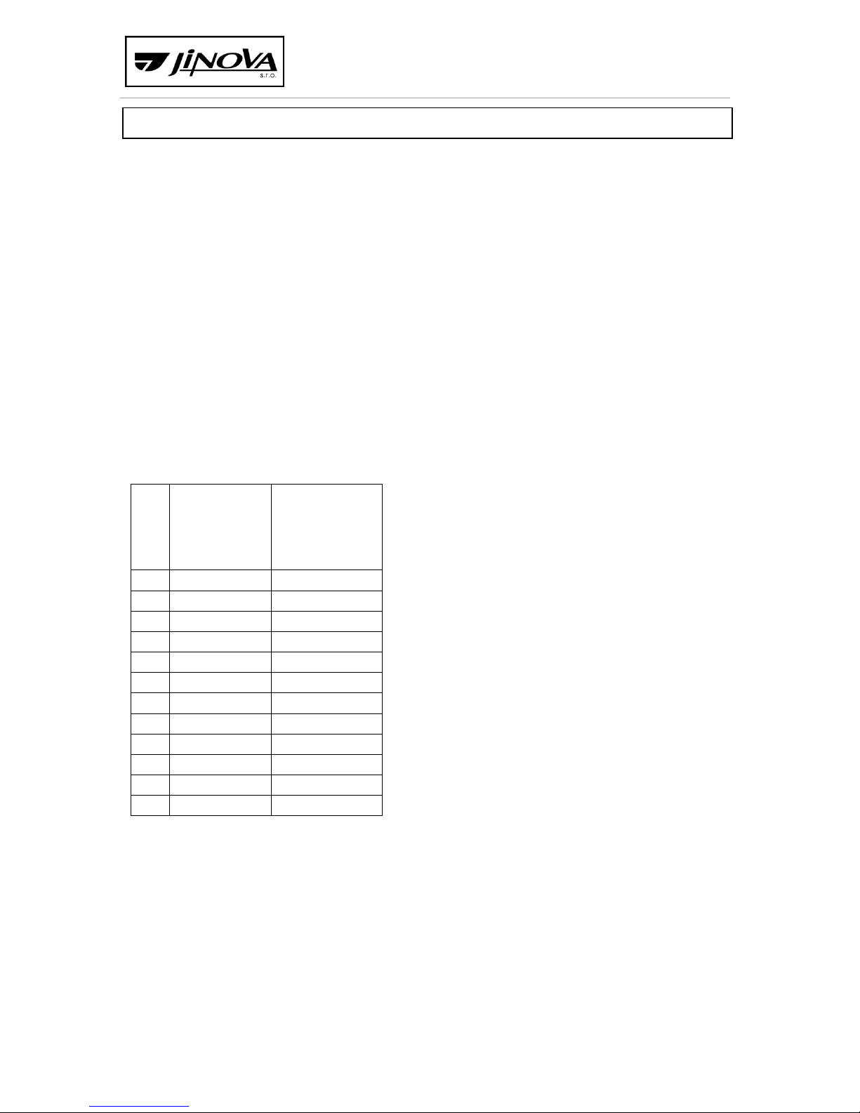
The basis of the MTP-V heater is always the BK heat exchanger selected according to
the required output; the required output is then the nominal output of the heater. The heat
exchanger table is below. The heat exchanger may be extended or shortened according to
the spatial disposition. Depending on customer requirements or specific needs, the heat
exchangers are made of steel of class 11 and stainless-steel materials.
Each heater has a nominal amount of air determined. With less air, the heater
cannot be operated for the required output.
The optimal air dT passing through the heat exchanger is c. 30 °C, so as to avoid
unwanted excessive condensation, so that the flue gas temperature is relatively low, and
the resistance of the heat exchanger on the side of the air is not too high. Basically, the
bypass is designed to keep “excess” heated air in the heater out of the heat exchanger.
The specific technical parameters of the supplied heater are always included in this
documentation in the “Certificate of product quality and completeness” and on the
nameplate.
Table of MTP-V technical parameters
BK
maximum heat
output
standard
design
minimum air
flow standard
design
kW
m3/h
P1
45
2400
P2
60
3300
37
50
2700
65
85
4600
100
130
7100
150
180
9800
225
300
16300
400
500
27100
525
650
35300
650
790
42900
1000
1100
59700
4. MTP Specifications:
MTP heaters are always supplied as a composition of a heat exchanger unit and
radial fan. The heat exchanger unit is not fitted with a bypass. The frame consists of welded
steel profiles, usually in a compact monoblock design.
MTP air heaters are delivered in an upright or horizontal design. Both versions can be
equipped with a wide range of accessories such as e.g. blind shutters, filters, elastic
connections, etc. that do not affect the function of the gas heater.
The heaters are supplied with fans and engines as required by customers with the
required disposition pressure for connection to air-conditioning piping.
Page 8
Do Žlábku 733, 514 01 Jilemnice
Subject: MTP Technical documentation Page No./No. of pages: 8/20
The casing is made with sandwich panels with mineral insulation of 30 mm. Surface
treatment of panels is made of galvanized sheet metal. At customerʼs request, the heater
can be supplied in any desired colour according to the RAL sampler.
The design for the outdoor environment is supplemented with a cover for the
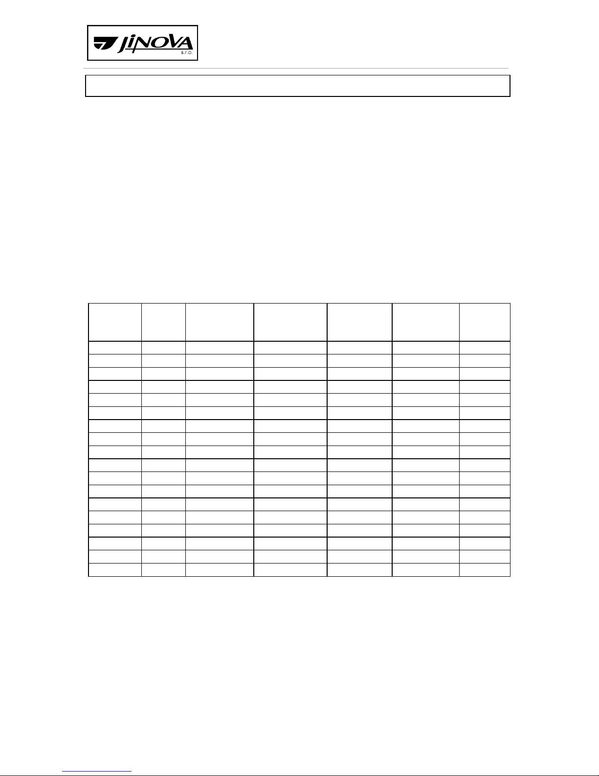
burner, or with a roof. Compared to the standard technical parameters stated below, the
parameters can be adjusted according to the application requirements by using the
appropriate engines and by adjusting the amount of air and heat output, always only within
the parameters of the corresponding heat exchangers and MTP-V. The specific technical
parameters of the supplied heater are always included in this documentation in the
“Certificate of product quality and completeness” and on the nameplate.
MTP air heaters can be equipped by the manufacturer with an electrical switchboard
located on the heater or designed for a stand-alone installation that provides control of the
burner, engine protection and start up and triple thermostat safety functions.
Table of MTP technical parameters
TYPE
Max.
heat
output
Air flow
Output
pressure
Consumption
- natural gas
Nominal input
Weight
kW
m3/h
Pa
m3/h
kW
kg
MTP 25
29
2200
40 - 300
3.11
0.50 - 1.00
220
MTP 37
45
3000
40 - 260
4.87
0.50 - 1.00
220
MTP 50
60
4000
40 - 340
6.47
0.70 - 1.50
310
MTP 65
75
5100
40 - 260
8.06
1.15 - 1.90
310
MTP 85
100
6600
40 - 300
10.75
1.15 - 2.60
450
MTP 100
120
7500
40 - 280
12.94
1.15 - 2.60
450
MTP 125
150
10000
40 - 300
16.13
1.60 - 3.60
585
MTP 150
175
12000
40 - 340
18.82
2.70 - 4.50
590
MTP 175
200
14000
40 - 360
21.50
2.70 - 4.50
800
MTP 225
260
18000
40 - 260
29.97
4.70 - 6.20
803
MTP 300
350
24000
40 - 380
37.63
6.50 - 12.00
1100
MTP 350
400
28000
40 - 450
43.00
8.50 - 16.00
1120
MTP 400
465
32000
40 - 280
49.98
12.00 - 16.00
1200
MTP 525
600
41000
40 - 250
64.51
17.00 - 20.50
2300
MTP 650
750
52000
40 - 280
80.64
17.00 - 24.00
2800
MTP 850
990
62000
40 - 300
106.43
25.00 - 33.00
5700
MTP 1000
1160
73500
40 - 300
124.74
25.00 - 33.00
6000
5 MTP-AL Specifications:
MTPAL air heaters are produced in block and chamber designs. They are produced
only in a horizontal design on the base frame.
The gas heating components are always equipped with a ventilation bypass
with a valve. The fans are on a common frame with the engine and stored on the vibration
isolators. The units are supplemented by a basic range of pocket filters, valves, mixing
chambers and other common accessories that do not affect the function of the gas heater.
The unit frames are made from modular aluminium profiles of a square cross section
with a side length of 50 mm. The casing is done with respect to the maximum thermal
Page 9
Do Žlábku 733, 514 01 Jilemnice
Subject: MTP Technical documentation Page No./No. of pages: 9/20
insulation of the unit from sandwich panels filled with mineral wool of thickness of 45 mm.
Panels are reinforced with glued and riveted profiles for firmness and durability.
Panels are attached into the aluminium frames according to their position with
rivets, bolts and nuts, plastic fasteners or hinges and handles. In addition to standard highquality seals, the panels without the need for access regarding the outdoor units are
cemented. Panels can be supplied powder-coated in any colour according to the RAL
sampler at the customerʼs request and for an extra charge.
All parts of the unit are produced as standard in silicon-free design.
The heaters are supplied in designs for indoor and outdoor use.
The fan component of the heaters is equipped with radial fans or fans with a free
impeller, with the amount of air and heat output as required by the customer. The engines
are together with the fans located on an integral frame.
The specific technical parameters of the supplied heater are always included in this
documentation in the “Certificate of product quality and completeness” and on the
nameplate.
MTPAL can be equipped with a wide range of accessories such as e.g. blind shutters,
filters, recuperators, cooling exchangers, elastic connections etc. that do not affect the
function of the gas heater.
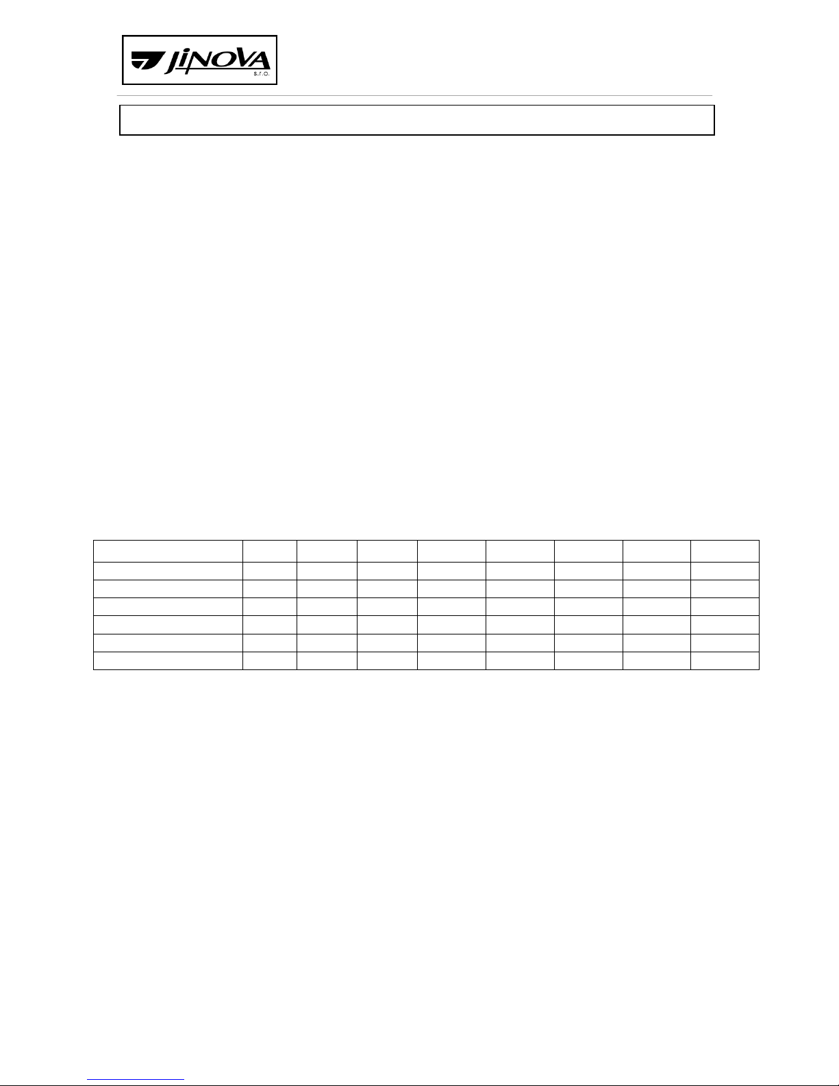
Table of MTP technical parameters
parameters/type
50
80
150
200
300
500
700
900
max. output [KW]
50
80
140
200
275
460
700
900
max. flow at 300 Pa
5200
8800
12500
18000
25000
36000
48000
60000
standard engine [KW]
1.1 - 3
2.2 - 4
3 - 5.5
4 - 7.5
5.5 - 11
11 - 18.5
15 - 30
22 - 30
BK
P1-37
37-65
37-100
37-150
37-225
37-400
37-525
37-650
cross section width [mm]
900
1100
1350
1450
1600
2000
2400
2800
cross section height [mm]
700
900
1000
1250
1500
1650
2100
2200
6. Working conditions and conditions for installation
The function of the air heater can only be guaranteed if the following working
conditions are met:
(a) compliance with the following parameters:
- nominal heat input (kW)
- nominal air flow (m3/h)
- external resistance must correspond to the proposed value
- input temperature (for standard design up to 40 °C, unless otherwise
specified)
- prevention of the chimney effect and return flow
- correct connection of thermostats T1, T2, T3
b) compliance with the environment
The air heaters are made in indoor or outdoor designs.
- the indoor design with IP 40 electrical protection can be used in an ordinary basic
environment.
Page 10

Do Žlábku 733, 514 01 Jilemnice
Subject: MTP Technical documentation Page No./No. of pages: 10/20
- the outdoor design with IP 43 electrical protection is designed for outdoor
environment. The burner and the triple thermostat are provided with appropriate
covers to protect these devices against atmospheric precipitation.
- with this design, prevention of the possibility of sucking up coarse dirt (e.g. leaves
from trees).
c) no flammable materials can be stored in the area of the air heater - fire hazard!!!
The heater interference suppression corresponds to ČSN 334200.
d) if the air heater is supplied in a design without the fan or without electrical
installation and MaR system, it is necessary to ensure their connection and
installation according to the applicable standards for gas equipment, thus in
particular 2016/426.
7. Technical supervision and inspection
Technical supervision and inspection during production as well as acceptance are
performed by the technical committee of the manufacturer.
Furthermore, the manufacturer reserves participation of their representative in
putting the heater into service as the warranty condition.
8. Marking
On each heater there is a non-removable label that contains:
a) manufacturerʼs designation
b) product identification number
c) type designation
d) serial number
e) year of production
f) nominal heat input (kW)
g) nominal heat output (kW)
h) nominal air flow (m
3
/h)
i) external air pressure (Pa)
j) nominal electrical input (kW)
k) weight (kg)
l) voltage system (3x400 V + N + PE 50 Hz)
m) protection
n) destination country
In addition, on each heat exchanger unit there is a label with the following text:
“This heater must be installed in accordance with the applicable instructions and its use is
permitted only in a well-ventilated area. Please read the instructions before installing and
using it.”
Page 11

Do Žlábku 733, 514 01 Jilemnice
Subject: MTP Technical documentation Page No./No. of pages: 11/20
9. Testing
Type tests
These tests are carried out by the Engineering Test Institute, Public Enterprise in
Brno, test room 202, Hudcova 56b, 621 00 Brno.
Production tests
These tests are carried out at production plant JINOVA s.r.o., Do Žlábku 733,
Jilemnice on each produced heat exchanger unit.
The following tests and checks are carried out in terms of production tests:
- cabinet welds check
- heat exchanger welds check
- external connection dimensions check
- surface treatment check
- check of completeness of the device and accessories
- check of electrical connection
See: “Unit test report”
Packaging, transport and storage
- Supplied heaters are packaged on the request of the customer in a fixation foil to
reduce damage of the surface treatment and are stored on wooden prisms or
pallets.
- It is necessary to ensure careful handling during transport and loading. Handling
must be carried out only via the pallet, the lower frame (between the wooden
prisms) or the welded loop. If there are two loops on the device, it is necessary to
use both of them, suspension on one loop is not permitted! Packaging must not be
exposed to direct influences of weather, long-term exposure to humidity and
impacts.
- Storage of heaters must be carried out in well-ventilated rooms without the effects
of corrosive vapours and aggressive gases or under a shelter that safely covers the
heater against atmospheric precipitation.
INSTRUCTIONS FOR INSTALLATION
Installation of the heater in place
The heater is placed on a horizontal, solid enough floor or frame. It is necessary to
keep the horizontal position of the heater, or slight slope towards the condensate
outlet to ensure its easy drainage. The slope must not be greater than 5 mm in
width of the heater. The location must be such as to allow the combustion chamber to be
replaced and the tube space to be cleaned. This means that at the front (on the side of the
burner) there must be free space equal to the dimensions “length x width x height” of the
heater. On the panel covering the tube plate of the heat exchanger chamber (opposite the
chimney), nothing can be installed there due to dismantling when cleaning the tube plate.
Page 12

Do Žlábku 733, 514 01 Jilemnice
Subject: MTP Technical documentation Page No./No. of pages: 12/20
For the outdoor design when placed on the roof of the building, the installation
company is obliged to provide the heater with a lightning conductor in accordance
with ČSN EN 62 305.
Safety distances
The actual distance of the air heater from the flammable material must not be less
than the safety distance that is 200 mm, according to ČSN 06 1008:97. If this distance
cannot be met, it is necessary to use a protective screen made of flammable material A or B.
The thickness of the protective screen must be at least 3 mm. The protective screen must
have a permanent position between the appliance and the protected material at a distance
(30 + 5 mm) from the protected material. The protective screen must extend beyond the
protected material to the nearest wall (ceiling) of non-flammable material, but at least
300 mm on the top and 150 mm on the sides. When using the protective screen, the
required distance can be reduced by no more than half.
If the heater is installed on the floor of flammable material, an insulating, nonconducting pad is used in this case. The material used for insulating pads - the degree of
flammability A, B, must be resistant to the mechanical effects of the load. The dimensions of
the pad must be at least the same as the heater floor plan. The thickness of the insulating
pad must be at least 5 mm.
No flammable materials can be stored at the location of the heater, as this could
create a fire hazard!
Interconnection of air-conditioning circuit
The air-conditioning piping can be screwed directly onto the frame or through the
flange damping insert. The connection on the inlet and outlet side of the air heating
element must always be a full-area connection, in case of connection to sub-accessories
according to the specification of this accessory.
Connection to smoke flue
The installation of the smoke flue must comply with all applicable regulations and
must be carried out by a specialist company. For calculation of the smoke flue, 0 Pa per
throat and the mass flow of flue gases according to the burner setting and the heat input
(usually approx. 14 kg/h for every 10 kW of output) is considered.
Note : Each heater fitted with a gas overpressure burner must be connected through
a separate smoke flue to a separate chimney flue.
Page 13

Do Žlábku 733, 514 01 Jilemnice
Subject: MTP Technical documentation Page No./No. of pages: 13/20
The necessity for all designs of MTP heaters is to ensure condensate drainage from
the chimney flue.
Condensate drainage
If the heater contains condensate drainage, it is advisable to ensure condensate
drainage from the heater. Condensate drainage must be designed in such a way that it
cannot be frozen in the winter period (for outdoor installations).
Assembly of burner
The heat exchanger units are fitted with pressure burners with one-stage, two-stage
or continuous regulation for the respective heating medium and according to the required
output given by the designer. Min. output of the burner is generally set to 50-65 % of the
nominal output. It cannot be operated in the full range of the work field. The nominal
output is set according to gas pressure, swirler and air damper. The burner is not part of the
supply of heat exchanger units.
Prior to installing the burner, it is necessary to tighten the burner flange bolts.
The heating medium connection must be carried out by a specialist company
(according to the relevant project) and must comply with the standards for
operation of the given type of burner.
The gas supply and orientation of the burner must be such that the gas inlet does
not prevent service access to the tube plate cover. For this reason, it is advisable to
lead the gas supply to the burner in the direction of the air flow. If this is not
possible, it is necessary to allow easy dismantling of the part of the piping in front of the
removable panel above the tube plate cover.
Assembly and adjustment of the burner will be performed by a service worker of the
burner manufacturer or an authorized worker. After the burner adjustment protocol has
been handed over and the relevant revisions have been made, the heat exchanger unit is
ready for approval and operation.
Heat exchanger units are, as standard, fitted with flanges with seals for assembly of
the burner by means of bolt connections. For the outdoor design of the heat exchanger unit,
the corresponding cover is screwed over the burner.
Before installation, check that the local conditions of fuel distribution, fuel
properties, overpressure and current heater settings are compatible.
Electrical installation
The electrical installation must be carried out by a specialist company which must
also provide electrical revision in the sense of ČSN 33 2000-6-61.
Page 14
Do Žlábku 733, 514 01 Jilemnice
Subject: MTP Technical documentation Page No./No. of pages: 14/20
Do not install any elements that make it difficult to dismantle the panel covering the tube
plate cover.
The ESD3J safety thermostat is not designed to regulate the required temperature. It is
placed in the heated air behind the heat exchanger, in its upper part max. 20 cm behind the
heat exchanger tubes. The contact of the safety thermostat T1 must be connected to the
burner feed phase to ensure that it is switched off in any (even malfunctioning) condition of
the burner.
The contact of the operating thermostat T2 is connected to the control terminals
circuit (usually marked T1 and T2) of the burner and it switches it off when the temperature
is above the set value.
The contact of the fan thermostat T3 ensures switching on of the fan and its
slowdown
(cooling the combustion chamber) when the burner is switched off.
Recommended electrical connection, see drawing No.:
3-JH-2001C - for ESD3J electronic thermostat
The heater is equipped with a clamp for protective connection according to ČSN 32 2000-
4.41.
For the outdoor design of the heater, the triple thermostat is provided with a cover.
Once connected, it is necessary to check the direction of speed of the fan engine!
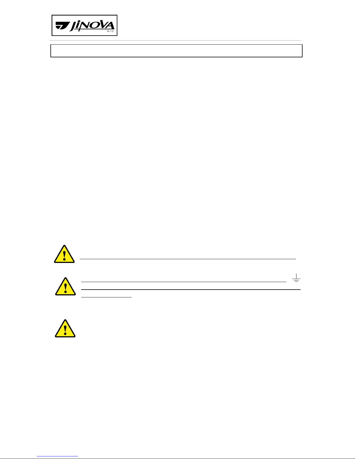
In case of a triple thermostat, it is absolutely necessary to connect the clamp
with PE conductor to prevent the influence of any induced voltages on the
thermostat sensor.
Note: It is not possible to switch off the whole device (both burner and fans)
without ensuring fan slowdown to cool the heat exchanger. The heat
accumulated in the heat exchanger could damage the surrounding equipment
due to the flow! It must not be possible to switch off the fans and leave the
burner on!
OPERATING INSTRUCTIONS
For the burner installed on the heat exchanger unit, the “Instructions” supplied
together with it by the manufacturer, apply to it.
Each heater is fitted at the output with a triple thermostat that provides safe
operating mode. This thermostat is not designed to regulate the required temperature.
Page 15

Do Žlábku 733, 514 01 Jilemnice
Subject: MTP Technical documentation Page No./No. of pages: 15/20
T1 - safety
- switches the burner off by disconnecting its supply voltage and it is blocked
in its off state. To enable a new automatic start of the burner, it is necessary
to press the button on the triple thermostat. Between the moment of the
burner blocking and the unblocking of the triple thermostat, the temperature
must drop below the value set on the thermostat T1. The condition for restart
of the heater is removing the cause of overheating.
The electronic thermostat used allows remote resetting of the safety
thermostat T1 (e.g. by a button located on the door of the control cabinet),
which is advantageous for heat exchanger units located in poorly accessible
places (e.g. suspended from the ceiling).
In the event of a power supply failure (during burner operation), due to the
accumulated heat in the heat exchanger chamber and the fan malfunction,
the temperature will increase. If the temperature exceeds the value set on
the safety thermostat T1, this thermostat will disconnect the burner supply.
The electronic thermostat resets itself when the network is switched on again
if the temperature has already dropped below the set value (for a long-term
power outage). For a short-term power outage, it is necessary to wait for the
fan to cool the chamber and to reset it by pressing the button on the
thermostat.
T2 - operational
- switches off the burner when the set temperature is exceeded and switches
it on again when the temperature drops
T3 - fan
- switches the fan on after reaching the set temperature, ensures fan
slowdown and cooling the chamber after switching off the burner.
Important information
The main switch can only be switched off after the fan has been completely
stopped. For longer shutdowns, it is necessary to close the fuel supply.
After professional commissioning, the set device parameters cannot be further changed to
ensure trouble-free operation.
In order to increase safety, we recommend the operator to inspect this heating system at
least once a year by a supplier worker or a service worker!
The heater can only be operated by persons over the age of 18.
The heater can only be operated by persons physically and mentally competent for this
activity.
Page 16
Do Žlábku 733, 514 01 Jilemnice
Subject: MTP Technical documentation Page No./No. of pages: 16/20
MAINTENANCE INSTRUCTIONS
The maintenance of the heater is always carried out while it is out of service.
Maintenance service must be in accordance with the operating instructions.
The following activities are performed during maintenance:
a) To ensure at least once a year, in accordance with the valid Decree 85/1975 Coll.,
checking and adjusting of the burner by an authorized mechanic (preferably before
the start of the heating season). The operation of the heater is required for adjusting
the burner.
Inspections and revisions of gas equipment
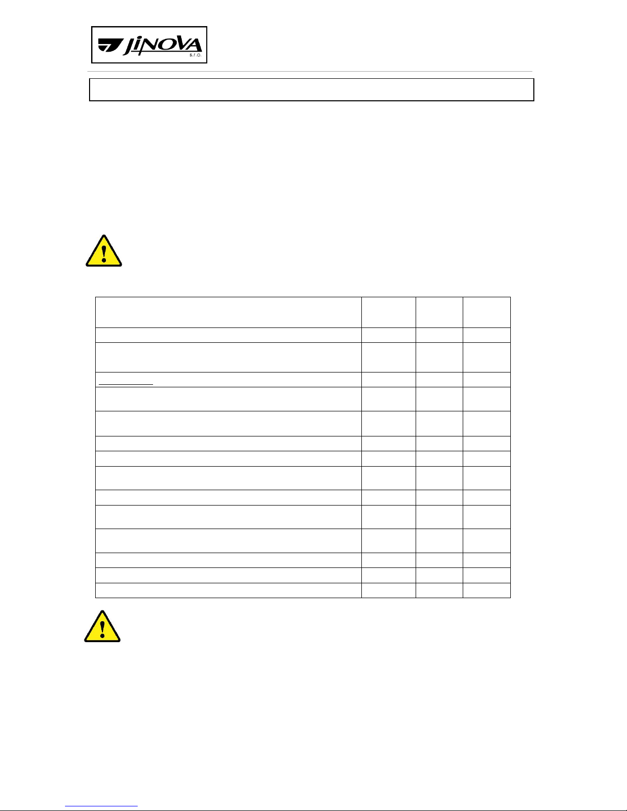
Gas
Gas
Service
control
control
inspection
When:
1 year
3 years
1 year
Who:
operator
inspecting
service
technician
technician
What is done:
Check of the location, functionality and tightness of the main
valve
X
X
Check of the location, functionality and tightness of branch
closures of ascending lines
X
X
Check of the location, functionality and tightness of gas meters
X
X
Check of the location, functionality and tightness of regulators
X
X
Check of the location, functionality and tightness of gas
appliances.
X
X
Check of the location of appliances in terms of space ventilation
X
Visual check of the location and condition of the common space
gas pipeline
X
X
Overall visual check of the location and condition of the domestic
gas pipeline
X
Check of the tightness of all detachable joints
X
X
Check of the presence of CO (carbon monoxide)
X
Cleaning, adjustment and check of gas appliance
X
b) Tightening the bolts of the burner plate and the tube plate cover, check after the
first month of operation, then regularly before the start of the heating season.
c) Cleaning the tube plate and the condensate drainage at least once a year (as
needed). For LFO (light fuel oils) and diesel burners, cleaning of the tube plate
must be carried out regularly whenever the heating efficiency decreases (even
once a month, if needed). After cleaning, the bolts at the tube plate must always be
tightened properly, or, if necessary, the seal should be replaced (check tightening of
the bolts repeatedly after a month of operation!)
If the heater contains the following, we also check:
Page 17

Do Žlábku 733, 514 01 Jilemnice
Subject: MTP Technical documentation Page No./No. of pages: 17/20
d) Check of V-belt tension and wear (as needed).
e) Regular check of input filters (min. once a month) - if the heater is equipped with
them or they are in the air-conditioning line with the heater. When clogged, clean
them or replace the filter cloth. Filter clogging time depends on the intake air
pollution. Clogging of the filters significantly reduces the amount of air supplied by
the heater and increases the temperature of the heat exchanger chamber. The heat
exchanger may be overheated and thus its service life may be reduced.
f) Lubrication of fan bearings - applies only to some fans, e.g. fans with bearings for
high temperatures (of ADH-RDH K / K2 type).
Note: for MTP (MTPAL) standard sets, maintenance-free bearings with permanent
grease filling are used.
Defects:
a) Overheating of heat exchanger, failure of safety thermostat T1
- check whether the suction and discharge spaces (piping, ...) are passable
- check fan condition, loose V-belts, seized bearings
- check the filter cloth, or also filter inserts
- if the filters are not clogged, it is necessary to consult the defect with the
production plant.
b) Flue gases flow into the heated space or higher oxygen content is measured in flue
gases
- check bolt tightening of the tube plate cover and the burner flange.
- replace the seal of the burner flange and the tube plate cover.
- check whether the combustion chamber is not burned.
LIST OF ACCESSORIES AND SPARE PARTS
Spare parts are not supplied with the heater. For warranty repairs, the spare parts
are available at the production plant which is authorized to carry out warranty repairs on
the heater (except the burner).
Post-warranty and non-warranty repairs are arranged by the customers themselves,
the spare parts can be ordered at the production plant.
The warranty does not apply to V-belts and filter cloths.
This documentation provides the basis for elaboration of operating rules in
accordance with ČSN 386405.
Page 18

Do Žlábku 733, 514 01 Jilemnice
Subject: MTP Technical documentation Page No./No. of pages: 18/20
RELATED DOCUMENTS
This technical documentation follows the following standards:
ČSN EN 1020 Air heaters for solid, liquid and gaseous fuels.
ČSN 33 2000-1 El. regulations - El. equipment - Determination of basic characteristics.
ČSN 33 2000-5-51 El. regulations - El. equipment - Selection and construction of el.
equipment.
Chap. 51: General regulations
ČSN 33 2000-6 El. regulations - El. equipment - Initial revision procedures
ČSN 32 2000-4-41 Electrical equipment. Safety. Protection against electric shock.
ČSN 06 1008:97 Fire safety of local appliances and heat sources
ČSN EN 62305 ČSN el. regulations. Chapter: Lightning protection.
ČSN EN 60335-1 Safety of el. appliances for household and similar purposes
part 1; general requirements
Act No. 22/1997 Coll. as subsequently amended.
Government Regulation No. 22/2003 Coll.
EU Regulation 2016/426 on Gas Appliances (GAR)
Final protocol No. 40-11101 SZU Brno
LIST OF WARRANTY AND POST-WARRANTY REPAIR SERVICES
Warranty and post-warranty service of MTP air heaters is provided by our company:
JINOVA s.r.o. , Do Žlábku 733, 514 01 Jilemnice
tel.: 481 541 518, 481 549 351, e-mail: [email protected]
In case of use of Weishaupt burners, the warranty and post-warranty service is
provided by Weishaupt company; our company only provides regular burner
adjustment together with heater service.
Weishaupt s.r.o.
Strašnická 1C/3177
102 00 Praha 10
tel.: 272 652 142-5, 602 372 218, fax: 272,652,146
Alternatively, they recommend one of the contractual mechanics from the
immediate vicinity.
In case of use of Riello burners, the warranty and post-warranty service is provided
by the company:
GFE s.r.o.
Obránců Míru 132
503 02 Předměřice nad Labem
tel.: 495 581 864, fax: 495,582,045
Page 19

Do Žlábku 733, 514 01 Jilemnice
Subject: MTP Technical documentation Page No./No. of pages: 19/20
Alternatively, they recommend one of the contractual mechanics from the
immediate vicinity.
OPTIONAL EQUIPMENT
The air heater can be supplemented by additional, optional accessories, especially
those stated below, according to the wishes and requirements of the customer.
Fan component
The fan component of the units is combined with a diffuser chamber of suitable
length. The fans of MTPAL units are always radial fans with spiral cabinet, low-pressure or
medium-pressure fans according to customer requirements. According to specific
parameters, the fans are in basic design or in a reinforcing frame. Fan displacement can also
be oriented up or down, and it is also possible to have the air suction into the fan
component from vertical directions.
Engines are together with fans located on an integral frame that is stored in the unit
frame and, if necessary, is completely removable. The frame is fastened to the structure and
the unit cabinet panels; larger fans are attached to the base frame through a specially
reinforced floor panel. Transmission is provided by euro pulleys with V-belts.
Non-standard units are equipped with double fans with a shared shaft, or two
parallel fans.
The fan component, as a standard, includes a door for access to the engine and the
fan. Upon request it is possible to deliver fan components with eye-slits and transmission
coverings.
Filtration component
Standard filtration components can be equipped with a whole range of standard
cartridge filters - EU-3 to EU-9 class pocket filters, frame pre-filters, filters from synthetic
materials, from fibreglass etc. Upon request, we can also deliver carbon filters.
Pocket filters are produced from standard-size cartridges that are placed in lateral
guide rails. Filter replacement is then carried out by the customers themselves by simply
drawing the filters out one after another into the service side of the unit.
Mixing and valve components, valves
As a standard, the valve components are equipped with aluminium valves with
plastic boxes that fully cover the control wheels. This significantly reduces the possibility of
deposition of impurities in the wheel cogs and reduces demands on valve maintenance.
Mixing chambers are fitted with all-covering valves from outside, or with valves with
a small hole inside the mixing chamber, upon request of the customer or according to the
mixing ratio. In units for indoor use, the valves for suction of air from the surrounding
Page 20

Do Žlábku 733, 514 01 Jilemnice
Subject: MTP Technical documentation Page No./No. of pages: 20/20
environment are covered with grids, in units for outdoor use they can be complemented by
weather-proof blinds.
Valves with a small hole designed for connection of air-conditioning piping are,
as a standard, supplied with an elastic cuff.
The valves are supplied ready for fitting with actuators (actuators may already be
part of the supply) or with manual control. Large valves are split to allow multiple actuators
to operate. Mixing valves can be coupled with a pull rod for one joint control.
Recuperation chamber
The chamber for recovery of heat from exhaust air may be equipped with a rotary
heat exchanger or plate heat exchanger. The heat exchanger consists of a system of
aluminium plates (slats) connected to each other in such a way as to allow for alternate
passage of the exhaust and supplied air between the plates. In winter period, the exhaust
air transfers heat to the aluminium plates, and they then heat the supplied fresh air. The
plate heat exchanger can also
be used for mixing.
Cooling chamber
The cooling chamber is equipped with a Cu/Al plate heat exchanger, where water,
anti-freezing mix or other refrigerant can be the heat transfer medium, according to the
request of the customer. The heat exchanger is equipped with a gradient stainless-steel
condensate drainage pan and a dropper eliminator.
Burners
As a standard, Weishaupt pressure burners burning natural gas, propane-butane,
ELFO (extra light fuel oils) and other types of fuel are supplied with the unit. Burners are
supplied, as a standard, with two-stage or modulation regulation. Burners include complete
gas fittings, electrical controls and all safety features.
Electrical equipment of the units and MaR
The units can be supplied with control and protection elements in any range
according to the request of the customer. The units can be supplied, for example, only with
fitted actuators, can be supplied incl. basic control cabinet only to protect and start up the
main engines.
Regulation supplied with the unit is designed for particular action, e.g. in terms of
regulation requirements on room temperature (halls) or inlet temperature (e.g. paint
boxes).
Unit control can be manual (a combination of basic electrical control and manual
valve control), manually electronically from a security cabinet or through advanced
regulators with a link to other control systems.
 Loading...