

Page 1

20AB CNC SWISS TYPE LATHE20AB CNC SWISS TYPE LATHE
OPERATION MANUALOPERATION MANUAL
VER1.0 960518VER1.0 960518
Page 2

I N D E XI N D E X
CHAPTER 1CHAPTER 1
PREFACE AND SAFETY PRECAUTIONSPREFACE AND SAFETY PRECAUTIONS
1-11-1
1.1 1.1 SAFETY SAFETY SYMBOLS SYMBOLS AND AND WORDSWORDS
1.2 1.2 LOCATION LOCATION OF OF WARNING WARNING TAG TAG 1-21-2
1.3 1.3 SAFETY SAFETY PRECAUTION PRECAUTION 1-81-8
1.4 1.4 OPERATION OPERATION NOTICE NOTICE 1-111-11
CHAPTER 2CHAPTER 2 MACHINE OUTLINEMACHINE OUTLINE
2-12-1
2.1 2.1 MACHINE MACHINE INSTALLATION INSTALLATION AND AND POWER POWER ON/OFFON/OFF
2.2 2.2 MACHINE MACHINE DESCRIPTION DESCRIPTION 2-32-3
STRUCTURE OVERVIEW(JSL-20AB)STRUCTURE OVERVIEW(JSL-20AB)
STRUCTURE OVERVIEW (JSL-20BSTRUCTURE OVERVIEW (JSL-20B))
2-52-5
SYSTEM OVERVIEW(JSL-20AB)SYSTEM OVERVIEW(JSL-20AB)
2-72-7
SYSTEM OVERVIEW(JSL-20B)SYSTEM OVERVIEW(JSL-20B)
2-82-8
2.3 2.3 MACHINE MACHINE DIMENSIONDIMENSION
2-92-9
2.4 2.4 TOOL TOOL SYSTEM SYSTEM OVERVIEW OVERVIEW 2-112-11
2.4.1 CONSUMPTION PARTS LIST2.4.1 CONSUMPTION PARTS LIST
2.4.2 TOOL SYSTEM OVERVIEW2.4.2 TOOL SYSTEM OVERVIEW
2-122-12
CHAPTER 3CHAPTER 3
OPERATION AND PANEL INSTRUCTIONOPERATION AND PANEL INSTRUCTION
3-13-1
3.1 3.1 OPERATION OPERATION PANEL PANEL INSTRUCTIONINSTRUCTION
OPERATION PANELOPERATION PANEL
Page 3

FUNCTION CODEFUNCTION CODE
3-33-3
FUNCTION INSTRUCTIONFUNCTION INSTRUCTION
3-53-5
3.2 3.2 FANUC FANUC 32I 32I PANEL PANEL INSTRUCTION INSTRUCTION 3-103-10
FUNCTION KEY INSTRUCTIONFUNCTION KEY INSTRUCTION
3-113-11
3.3 3.3 G G CODE CODE LIST LIST 3-133-13
3.4 3.4 M M CODE CODE LIST LIST FOR FOR MAIN MAIN SYSTEM SYSTEM 3-143-14
3.5 3.5 M M CODE CODE LIST LIST FOR FOR SUB SUB SYSTEM SYSTEM 3-163-16
3.6 3.6 JSL-20AB JSL-20AB PARAMETER PARAMETER K K SERIES SERIES 3-173-17
3.7 3.7 JSL-20AB JSL-20AB PARAMETER PARAMETER D D SERIES SERIES 3-193-19
3.8 3.8 MACHINE MACHINE MOVEMENT MOVEMENT INSTRUCTION INSTRUCTION 3-213-21
MAIN MECHANICAL STRUCTUREMAIN MECHANICAL STRUCTURE
MAIN SPINDLE AND TOOL SYSTEMMAIN SPINDLE AND TOOL SYSTEM
3-223-22
GUIDE BUSHING HOLDERGUIDE BUSHING HOLDER
3-233-23
SUB SPINDLE AND TOOL SYSTEM(JSL-20AB/B)SUB SPINDLE AND TOOL SYSTEM(JSL-20AB/B)
3-243-24
3.9 3.9 MACHINE MACHINE SETTING SETTING AND AND ADJUSTMENT ADJUSTMENT 3-253-25
COLLET CHUCK INSTALLATION AND ADJUSTMENTCOLLET CHUCK INSTALLATION AND ADJUSTMENT
GUIDE BUSHING HOLDER INSTALL AND ADJUSTGUIDE BUSHING HOLDER INSTALL AND ADJUST
3-263-26
EJECT PART DEVICE INSTALLATIONEJECT PART DEVICE INSTALLATION
3-293-29
LONG PARTS CATCHERLONG PARTS CATCHER
3-313-31
LONG PARTS CATCHER INSTALLATIONLONG PARTS CATCHER INSTALLATION
Page 4

CHANGE GRIPPERCHANGE GRIPPER
3-333-33
3.10 3.10 SETTING SETTING MODE MODE OF OF GUIDE GUIDE BUSHING BUSHING HOLDER HOLDER 3-353-35
3.11 3.11 WAITING WAITING M M CODE CODE INSTRUCTION INSTRUCTION 3-363-36
PROGRAM EXAMPLE 1PROGRAM EXAMPLE 1
3-393-39
PROGRAM EXAMPLE 2PROGRAM EXAMPLE 2
3-443-44
PROGRAM EXAMPLE 3PROGRAM EXAMPLE 3
3-483-48
3.12 3.12 CUTTING CUTTING TOOL TOOL INSTALL INSTALL AND AND OPERATE OPERATE 3-533-53
MAIN SYSTEM O.D. TOOL INSTALLATIONMAIN SYSTEM O.D. TOOL INSTALLATION
SUB SYSTEM SIDE DRILLING INSTALLATIONSUB SYSTEM SIDE DRILLING INSTALLATION
MAIN SYSTEM FACE DRILLING DEVICE INSTALLMAIN SYSTEM FACE DRILLING DEVICE INSTALL
3-543-54
TOOL OPERATION OF SUB SYSTEMTOOL OPERATION OF SUB SYSTEM
SUB SYSTEM TOOL INSTALLATIONSUB SYSTEM TOOL INSTALLATION
3-553-55
3.13 3.13 EDIT EDIT AND AND EXECUTE EXECUTE NC NC PROGRAM PROGRAM 3-563-56
CREATE A NEW PROGRAMCREATE A NEW PROGRAM
CALL NC PROGRAMCALL NC PROGRAM
3-583-58
EXECUTE NC PROGRAMEXECUTE NC PROGRAM
3-593-59
3.14 3.14 G188/G284/G300 G188/G284/G300 INSTRUCTION INSTRUCTION 3-603-60
G188:MAIN SYSTEM X AXIS SIDE RIGID TAPPINGG188:MAIN SYSTEM X AXIS SIDE RIGID TAPPING
G284:SUB SYSTEM Z AXIS FACE RIGID TAPPINGG284:SUB SYSTEM Z AXIS FACE RIGID TAPPING
3-613-61
G300:PROGRAM ZERO POINT RETUNG300:PROGRAM ZERO POINT RETUN
3-623-62
Page 5

3.15 3.15 WORK WORK PIECE PIECE COUNT COUNT FUNCTION FUNCTION 3-633-63
CHAPTER 4CHAPTER 4MAINTAIN AND TROUBLESHOOTINGMAINTAIN AND TROUBLESHOOTING
4-14-1
4.1 4.1 TOOL TOOL OFFEST OFFEST FUNCTIONFUNCTION
4.2 4.2 TOOL TOOL GEOMETRY GEOMETRY COMPENSATION COMPENSATION 4-24-2
4.3 4.3 TOOL TOOL WEAR WEAR COMPENSATION COMPENSATION 4-34-3
4.4 4.4 TOOL TOOL NOSE NOSE RADIUS RADIUS COMPENSATION COMPENSATION 4-44-4
4.5 4.5 Y Y AXIS AXIS TOOL TOOL OFFSET OFFSET 4-64-6
4.6 4.6 ALARM ALARM MESSAGE MESSAGE AND AND TROUBLESHOOTING TROUBLESHOOTING 4-74-7
Page 6
1. PREFACE AND SAFETY PRECAUTIONS
1.1 SAFETY SYMBOLS AND WORDS
SAFETY SYMBOLS & WORDS
Following are safety symbols and words. They indicate potentially hazardous
situations which, if not avoided, may result in injury or damage to the machine.
Please read carefully and obey all warnings and instructions.
Symbol Definitions
DANGER
DANGER indicates a potentially hazardous situation
which, if not avoided, may result in death or serious
injury.
WARNING
WARNING indicates a potentially hazardous situation
which if not avoided, may result in machine malfunctions
or breakage. .
WARNING!!
*Please read and obey the following precautions.
DANGER
Hazardous Situations
1. To prevent electric shocks and incorrect operation, please close electrical
cabinet before operating machine.
2. It is necessary to close the door before machine running.
3. For the purpose of adjusting, measuring, or cleaning, stop the spindle
before operating.
4. Please notice that the tail of bar might be twisted and becoming
dangerous if bar feeding device is not working not normally.
5. Insufficient use of cutting oil while cutting may result in fire. Please confirm
that the cutting oil capacity is sufficient and check the pressure sensor
regularly before operating.
WARNING Danger of Machine Malfunction
Any attempt to modify or rebuild of this machine will cause unexpected danger.
1-1
Page 7
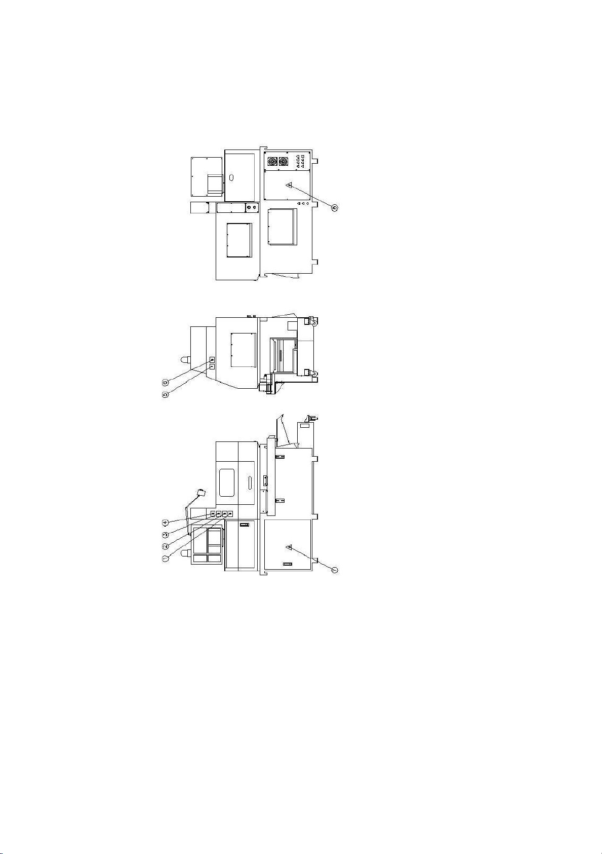
1.2 LOCATION OF WARNING TAG
1-2
Page 8
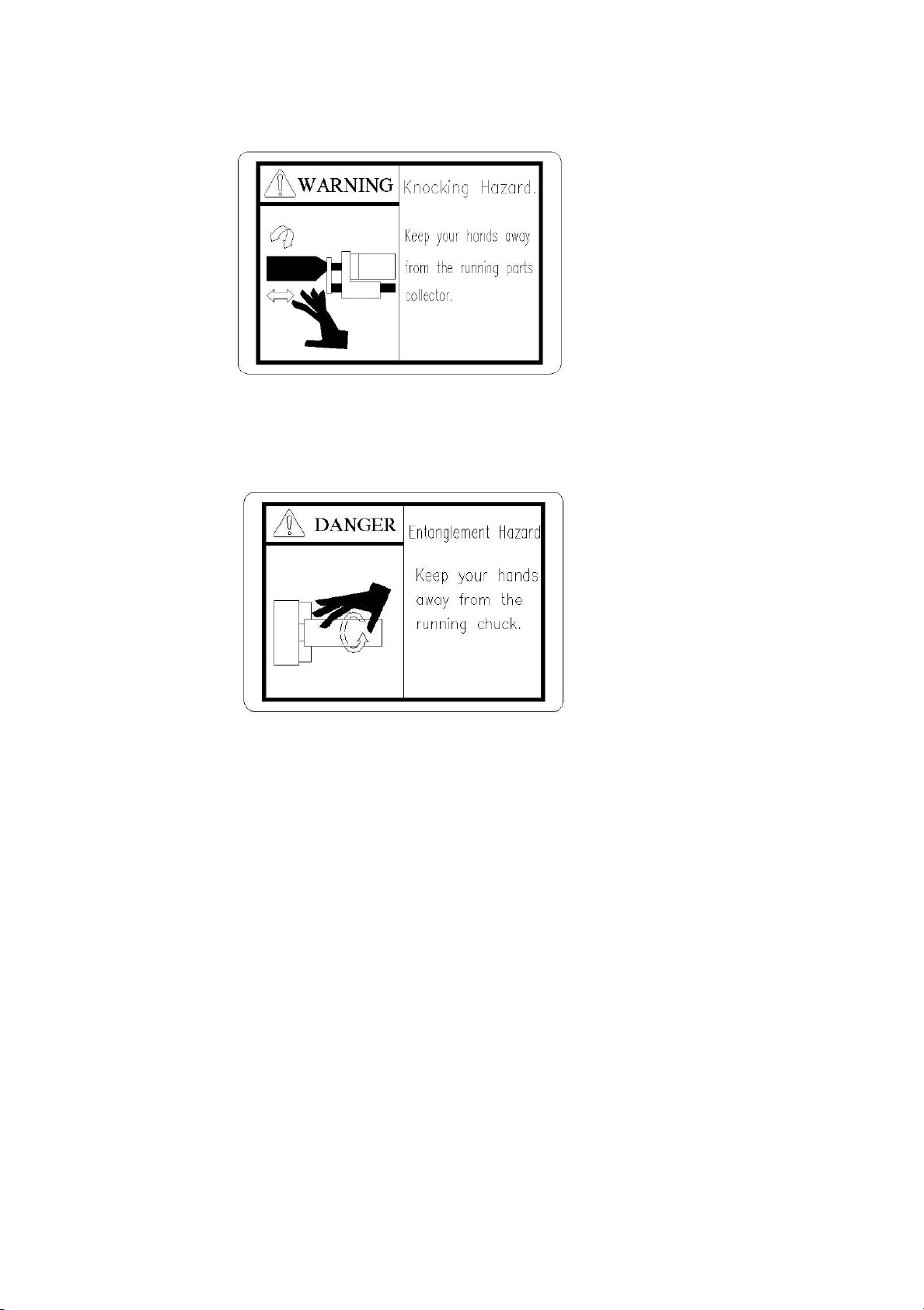
(1)
(2)
1-3
Page 9
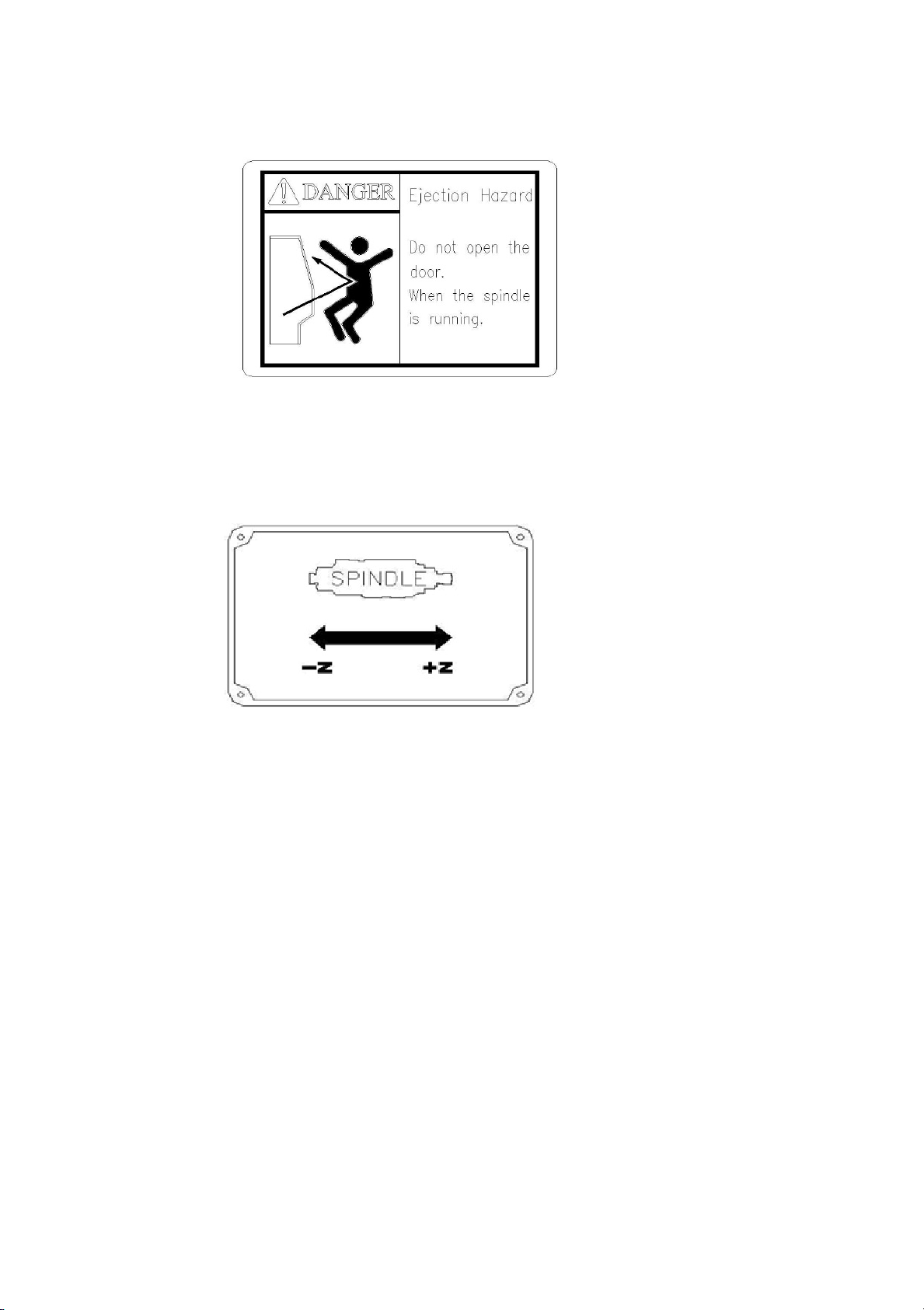
(3)
(4)
1-4
Page 10
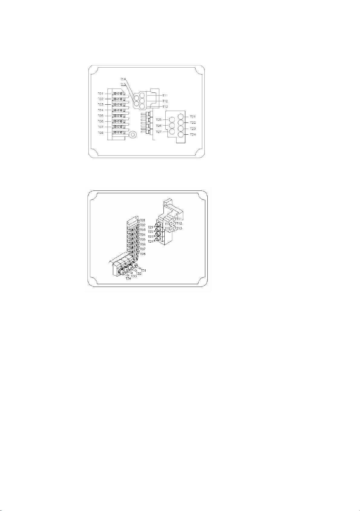
(5)
(5)
1-5
Page 11
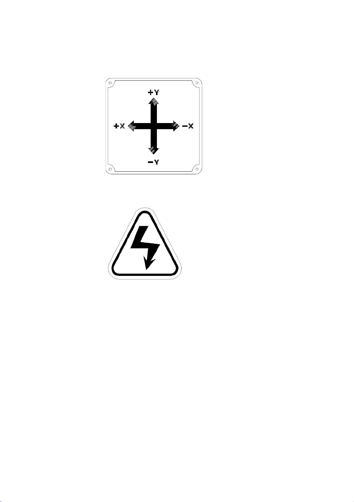
(6)
(7)(8)
High voltage and current inside electrical cabinet and operation panel.
Incorrect operation might cause electric shock and minor injury. It
indicates that only maintenance engineers can enter this area.
Please replace with new tag if it becomes blurred or faded.
1-6
Page 12

1.3 SAFETY PRECAUTION
WARNING Notice while maintenance
Be sure the machine situation after take out splash guard or sheet metal.
If not notice , following situations might happen;
1. Operator‘s cloth might be entangled by the spindle and will cause
unexpected danger.
2. Please keep staying in safety area to operate machine.
3. Please always free run machine while maintenance.
4. If practical machining is necessary, please keep staying in safety area to
run this machine.
Be sure the machine situation before open the electrical cabinet:
1. The tag of means high voltage area. Touch the area may get an
electric shock.
2. Please put a cover on the high voltage area before maintenance operation.
3. The wiring panel has many sharp components. Be careful while
maintenance operation.
For practical machining , please check following points before press cycle start
1. Use single block to adjust feed rate, machine lock or take out all tools and
material to use free run only.
2. Incorrect values, parameters, and NC program will cause unexpected
danger while machine is running.
3. For tool offset, please be sure the offset value and direction. With incorrect
values, it will cause unexpected danger and damage operator.
1-7
Page 13
WARNING Change controller spare parts
1. Switch off the main power and controller power before maintenance.
2. If only switch off the controller power, the servo amplifier may still active. It
will damage the devices or get an electric shock.
3. It is necessary at least two people to change the heavy device. Only one
person may damage by device falling down.
4. To change amplifier, please wait after switch off power 20 minutes.
5. Please keep same parameter values while change device.
6. Keep safety situation changing device , or it will cause unexpected danger.
WARNING Controller parameter setting
After modified parameters, install splash guard and sheet metal to start
machine running.
Please double check following steps for practical machining.
1. Use single block to adjust feed rate , machine lock or take out all tools and
material to use free run only.
2. Incorrect values, parameters, and NC program will cause unexpected
danger while machine is running.
WARNING CNC Parameter setting
The controller manufacturer has optimized the CNC and PMC parameter
values. Please do not change any values to avoid any unexpected danger.
WARNING Change Battery
The operation only allowed technicians who had been well trained in this field.
The tag of means high voltage area. Touch the area may get an electric
shock.
1-8
Page 14
WARNING Parameters Backup
Please backup all parameters in case of out of battery.
When low battery, the system will show alarm on the screen. Please do
change the battery in one week.
WARNING Change ABS. encoder Battery
The operation only allowed technicians who had been well trained in this field.
The tag of means high voltage area. Touch the area may get an electric
shock.
WARNING ABS. encoder value backup
The operation only allowed technicians who had been well trained in this field.
The tag of means high voltage area. Touch the area may get an electric
shock.
WARNING Change Fuse
To proceed
The operation only allowed technicians who had been well trained in this field.
The tag of means high voltage area. Touch the area may get an electric
shock.
1-9
Page 15

1.4 OPERATION NOTICE
BAR MATERIAL SELECTION
Please choose grinded bar material. The diameter tolerance should not
exceed 0.02mm, and chamfer both sides. It should not be twisted or deformed
in any way, otherwise the bar and guide bush holder will damage with each
other.
GUIDE BUSH HOLDER SELECTION
The specification of guide bush holder is suitable for TSUGAMI model 20. One
is tungsten steel and the other is ceramic. The tungsten steel guide bush
holder is good for cutting brass, aluminum, easy cutting steel, and medium
carbon steel. Others, like stainless steel are better for the ceramic guide bush
holder.
OPERATION OF GUIDE BUSH HOLDER
There are two ways to operate the guide bush holder. One is fixed guide bush
holder, and the other is rotary guide bush holder. Each one has its own
mounting device. The purpose of the guide bush holder is to hold the bar and
prevents vibration for long part turning. The suitable turning models are as
follows:
A. Fixed guide bush holder:It is good for turning the cylinder bar. It will not
rotate with spindle. Please notice that cutting oil must gush on the guide
bush holder for lubrication.
B. Rotary guide bush holder:It is good for turning the polygon bar. It will
rotate with spindle. Under this mode, the Z-axis traveling distance is about
90mm.
NOTE: To change mode, it is necessary to change the mounting device and
PN parameters. (Refer to 3.10)
GUIDE BUSH HOLDER ADJUSTMENT
A. The distance between the bar and fixed guide bush holder should not
exceed 0.03mm.
B. The distance between the bar and traveling guide bush holder should not
exceed 0.02mm.
TRAVELING GUIDE BUSH HOLDER
If the work piece is short (normally the length is shorter than 2.5 times diameter
and total length not exceeding 40mm). There is no guide bush holder for this
mode, but it is necessary to change mounting device and PN parameters.
(Refer to 3.10)
CUTTING TOOL SELECTION
1-10
Page 16

Please choose cutting tool for 12mm shank for swiss type lathe.
CUT OFF TOOL POSITION
The cut-off tool should be installed at No.8 tool position to prevent interference
while the parts catcher is active.
CUTTING OIL SELECTION
Please use good quality cutting oil for turning. The oil must gush on the guide
bush holder for lubrication between the bar and guide bush holder.
SIDE DRILLING DEVICE
Use M113 for CW, M114 for CCW, and the CNC system will change direction
itself.
(Refer to instruction of side drilling device)
1-11
Page 17

2. MACHINE OUTLINE
2.1 MACHINE INSTALLATION AND POWER ON / OFF
A. MACHINE INSTALLATION
1. Moving the machine to the specified place.
2. Place six machine base blocks at the specified location at the bottom of
machine.
3. Place leveling indicator to the plane below the control box (see Figure 1),
and adjust the screw until machine is on the horizontal plane.
4. Confirm each screw of machine base is screwed tight with base blocks.
5. Push coolant tank into machine base, and connect the pipe with coolant
motor.
6. Connect plugs of other motors with the outlet behind the machine.
7. Connect air unit with air compressor. The pressure should be at least
6Kgf/cm2
8. Open the electrical cabinet and connect with power and grounding.
9. Make sure the three phase cables connect with the correct terminals and
close the cover ( confirm the connection of three phase cable by checking
the rotating direction of coolant motor)
10. The safety distance between machines is one meter.
B. POWER ON
1. Make sure power cable connection is correct.
2. Turn on the switch at the left side of operation panel
3. Press green button (ON)
4. After the starting system procedure is finished, release EMERGENCY
STOP.
5. Finish ( no necessary to return home position)
C. Power OFF
1. Make sure machine is stopped.
2. Press EMERGENCY STOP.
3. Press red button (OFF).
4. Turn off the switch at the left side of the operation panel.
5. Finish.
2-1
Page 18
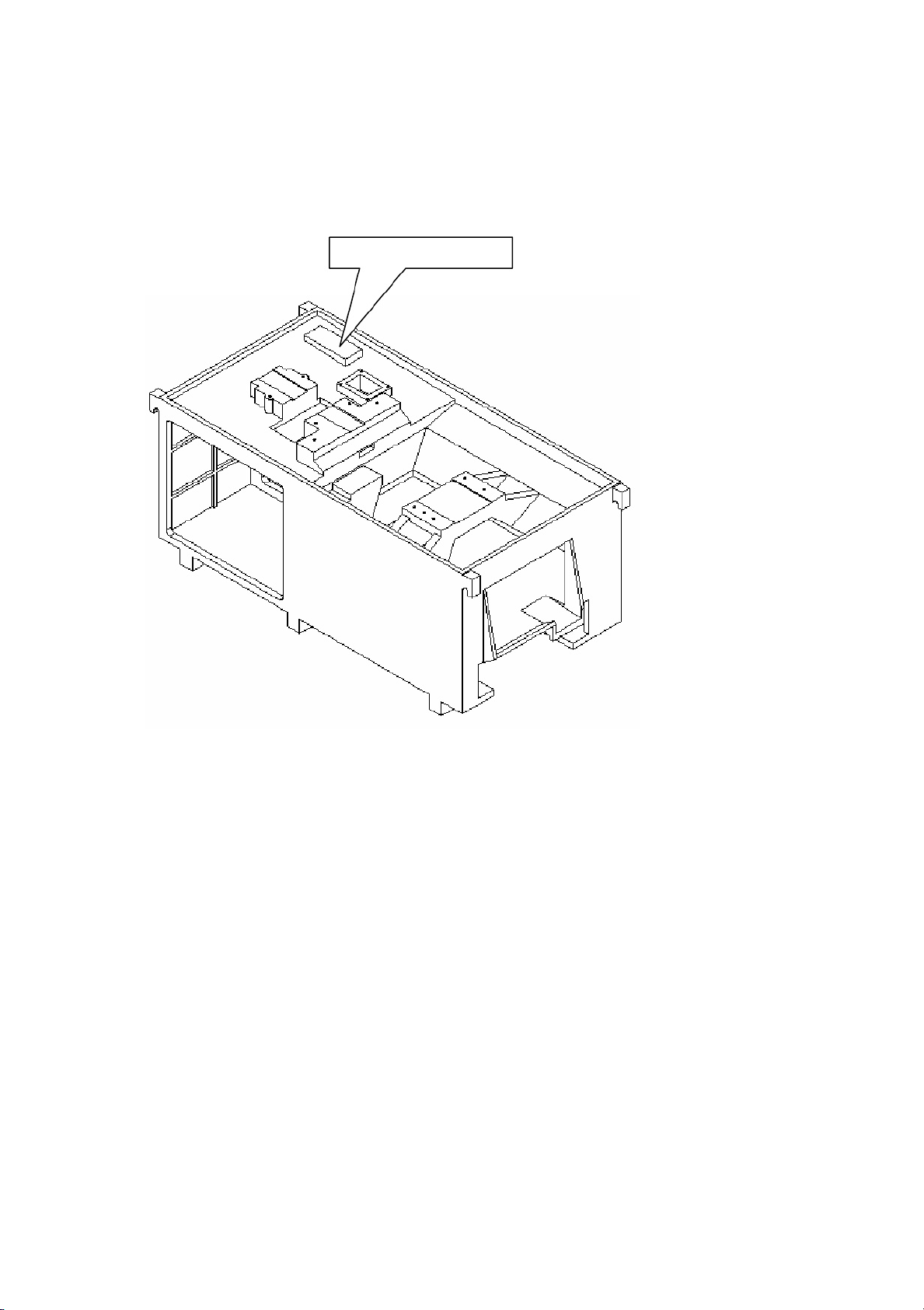
2
Leveling indicator plane
FIGURE 1
2-
Page 19
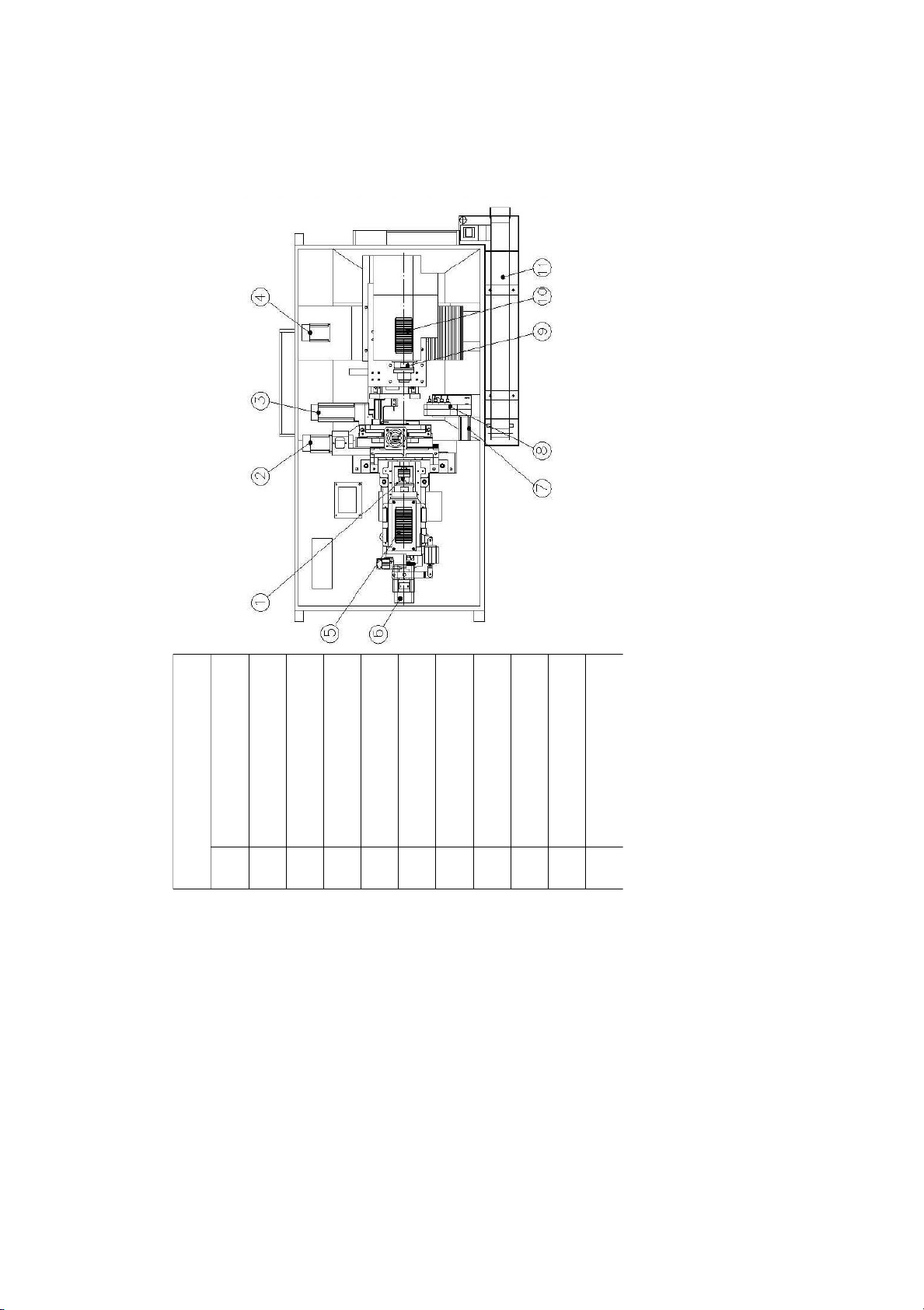
2.2 MACHINE DESCRIPTION
STRUCTURE OVERVIEW -1 (JSL-20AB)
S
p
i
n
d
l
e
X
1
-
a
x
i
s
s
e r
v
o
m
o
t
o
r
S
i
d
e
d
r
i
l
l
s e
r
v
o
m
o
t
o
r
X
2
-
a
x
i
s
s
e r
v
o
m
o
t
o
r
B
u
i
l
t
i
n
s
p i n
d
l
e
(
M
a
i
n
s
p
i
n
d
l
e
)
Z
-
a
x
i
s
s
e
r v
o
m
o
t
o
r
S
u
b
s
y
s
t
e m
d
r
i
l
l
s
e
r
v
o
m
o
t
o
r
S
u
b
s
y
s
t
e m
f
a
c
e
d
r
i
l
l
d
e
v
i
c
e
S
u
b
s
p
i
n
d l e
B
u
i
l
t
i
n
s
p i n
d
l
e
(
s
u
b
s
p
i
n
d
l
e
)
P
a
r
t
s
c
o
n
v e
y
o
r
D
e
s c
r
i
p
t
i
o
n
1 2 3 4 5 6 7 8 9
1
0
1
1
2-3
Page 20
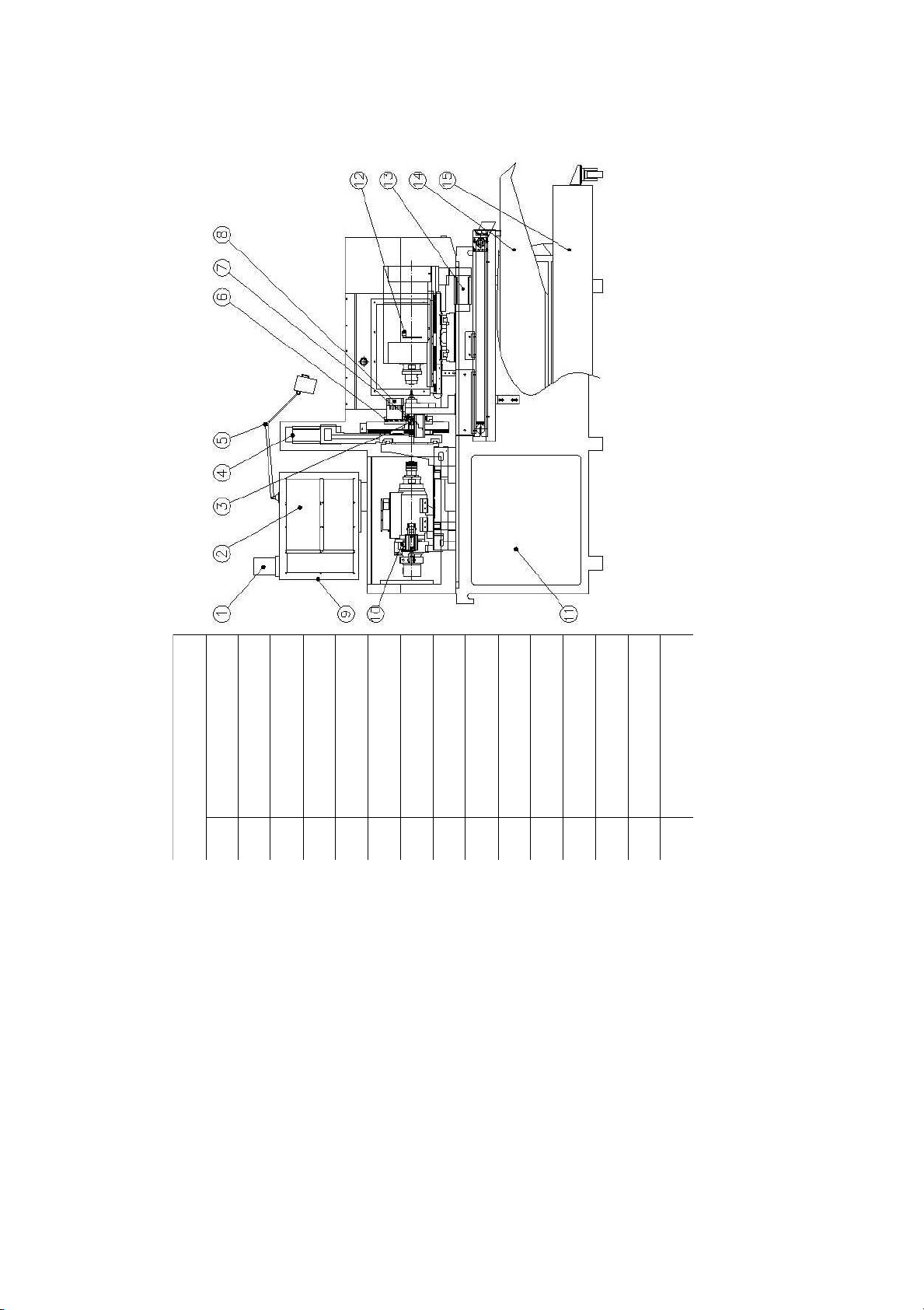
STRUCTURE OVERVIEW -2 (JSL-20AB)
A
l
a
r
m
l
a
m
p
O
p
e
r a
t
i
o
n
p
a
n
e
l
a
n
d
s
c
r
e
e
n
G
u
i
d
e
b
u
s
h
h
o
l
d
e
r
Y
-
A
x i s
s
e
r
v
o
m
o
t
o
r
L
i
g
h
t i n
g
d
e
v
i
c
e
T
o
o
l h
o
l
d
e
r
S
i
d
e
d
r
i
l
l
D
r
i
l
l
t o
o
l
h
o
l
d
e
r
P
o
w
e r
s
w
i
t
c
h
M
a
i
n s
p
i
n
d
l
e
e
n
c
o
d
e
r
E
l
e
c
t r
i
c
a
l
c
a
b
i
n
e
t
S
u
b
s
p
i
n
d
l
e
e
n
c
o
d
e
r
Z
2
-
a
x
i
s
s
e
r
v
o
m
o
t
o
r
C
h
i
p
c
o
l
l
e
c
t
o
r
t
a
n
k
C
o
o
l a
n
t
t
a
n
k
D
e
s
c
r
i
p
t
i
o
n
1 2 3 4 5 6 7 8 9
1
0
1
1
1
2
1
3
1
4
1
5
2-4
Page 21
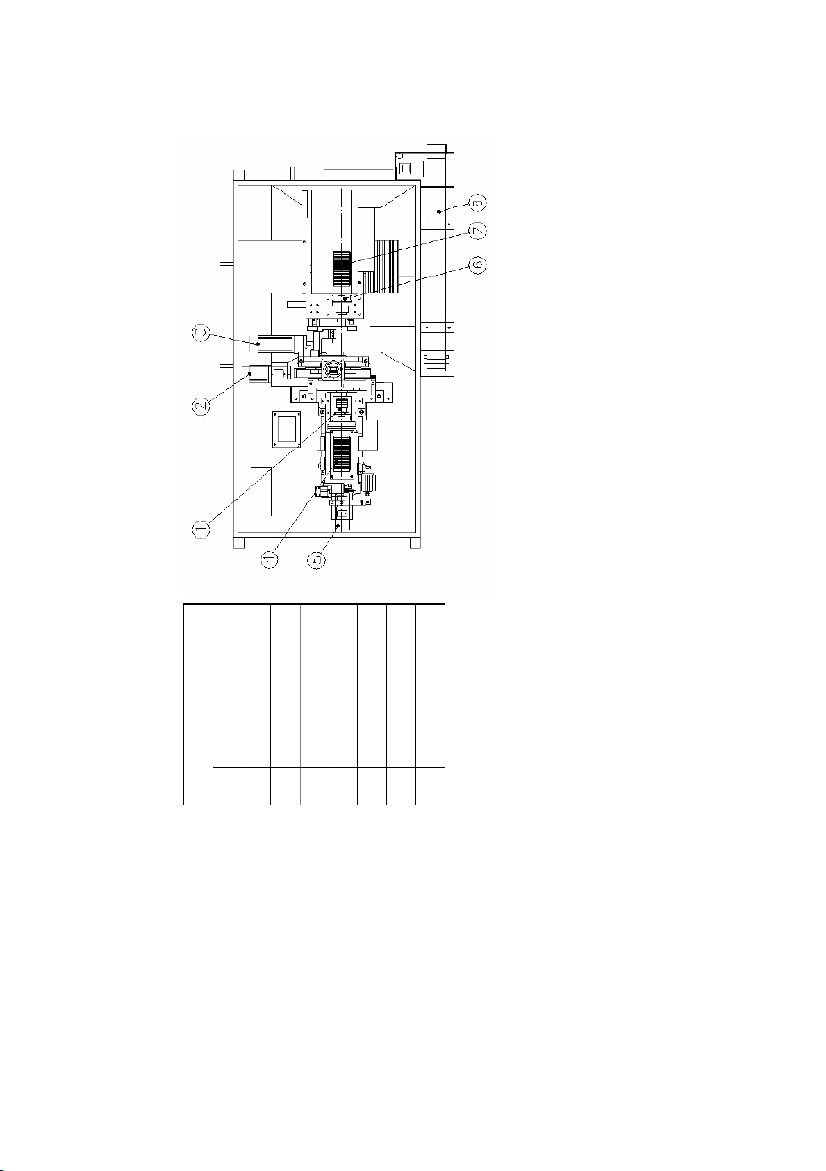
STRUCTURE OVERVIEW -3 (JSL-20B)
M
a
i
n
S
p
i
n
d
l e
X
1
a
x
i
s
s
e
r v o
m
o
t
o
r
S
i
d
e
d
r
i
l
l
i
n
g s
e
r
v
o
m
o
t
o
r
B
u
i
l
t
-
i
n
s
p
i
n d
l
e
s
e
r
v
o
m
o
t
o
r
Z
1
-
a
x
i
s
s
e
r v o
m
o
t
o
r
S
u
b
s
p
i
n
d
l
e
B
u
i
l
t
-
i
n
s
p
i
n d
l
e
s
e
r
v
o
m
o
t
o
r
P
a
r
t
s
c
o
n
v
e y
o
r
D
e
s
c
r
i p
t
i
o
n
1 2 3 4 5 6 7 8
2-5
Page 22
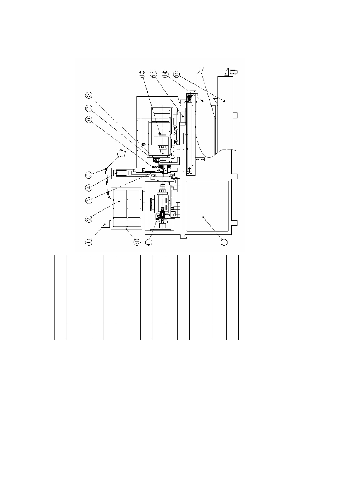
STRUCTURE OVERVIEW -4 (JSL-20B)
A
l
a
r
m
l
a
m
p
O
p
e
r
a
t
i
o
n
p a
n
e
l
G
u
i
d
e
b
u
s
h
Y
1
a
x
i
s
s
e
r v o
m
o
t
o
r
W
o
r
k
l
i
g
h
t
T
o
o
l
h
o
l
d
e
r s
y
s
t
e
m
S
i
d
e
d
r
i
l
l
i
n
g d
e
v
i
c
e
F
a
c
e
d
r
i
l
l
i
n
g
d
e
v
i
c
e
M
a
i
n
p
o
w
e
r s
w
i
t
c
h
M
a
i
n
s
p
i
n
d
l e
i
n
d
i
c
a
t
o
r
E
l
e
c
t
r
i
c
a
l
c
a b
i
n
e
t
S
u
b
s
p
i
n
d
l
e i
n
d
i
c
a
t
o
r
Z
2
a
x
i
s
s
e
r v o
m
o
t
o
r
C
h
i
p
c
o
l
l
e
c
t o
r
C
o
o
l
a
n
t
t
a
n
k
D
e
s
c
r
i p
t
i
o
n
1 2 3 4 5 6 7 8 9
1
0
1
1
1
2
1
3
1
4
1
5
2-6
Page 23
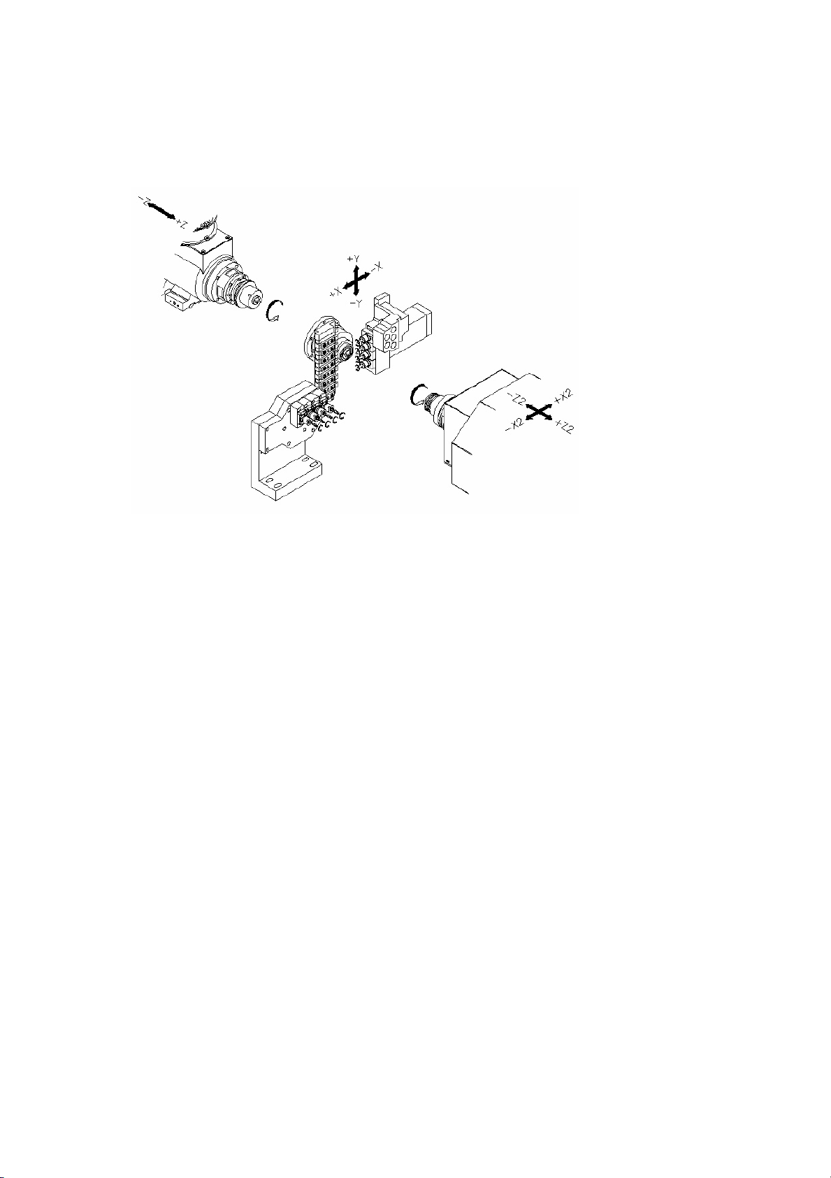
SYSTEM OVERVIEW (JSL-20AB)
2-7
Page 24
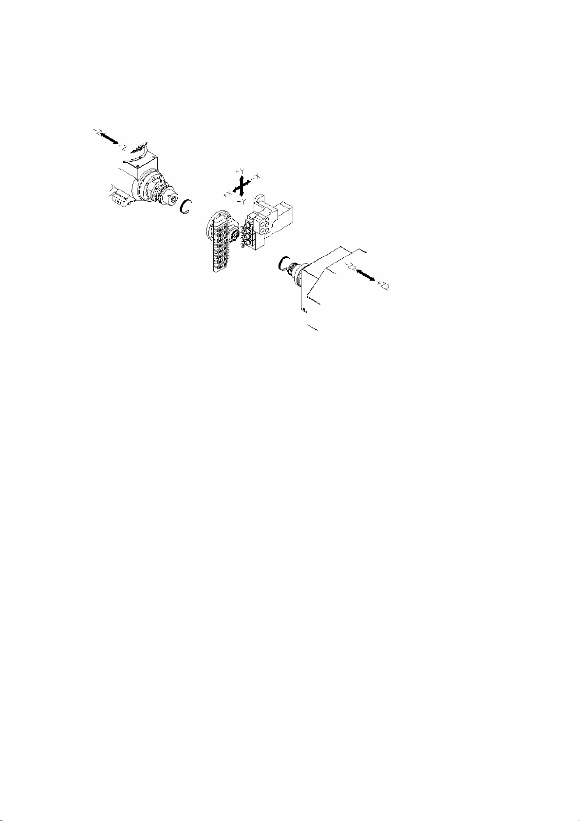
SYSTEM OVERVIEW (JSL-20B)
2-8
Page 25
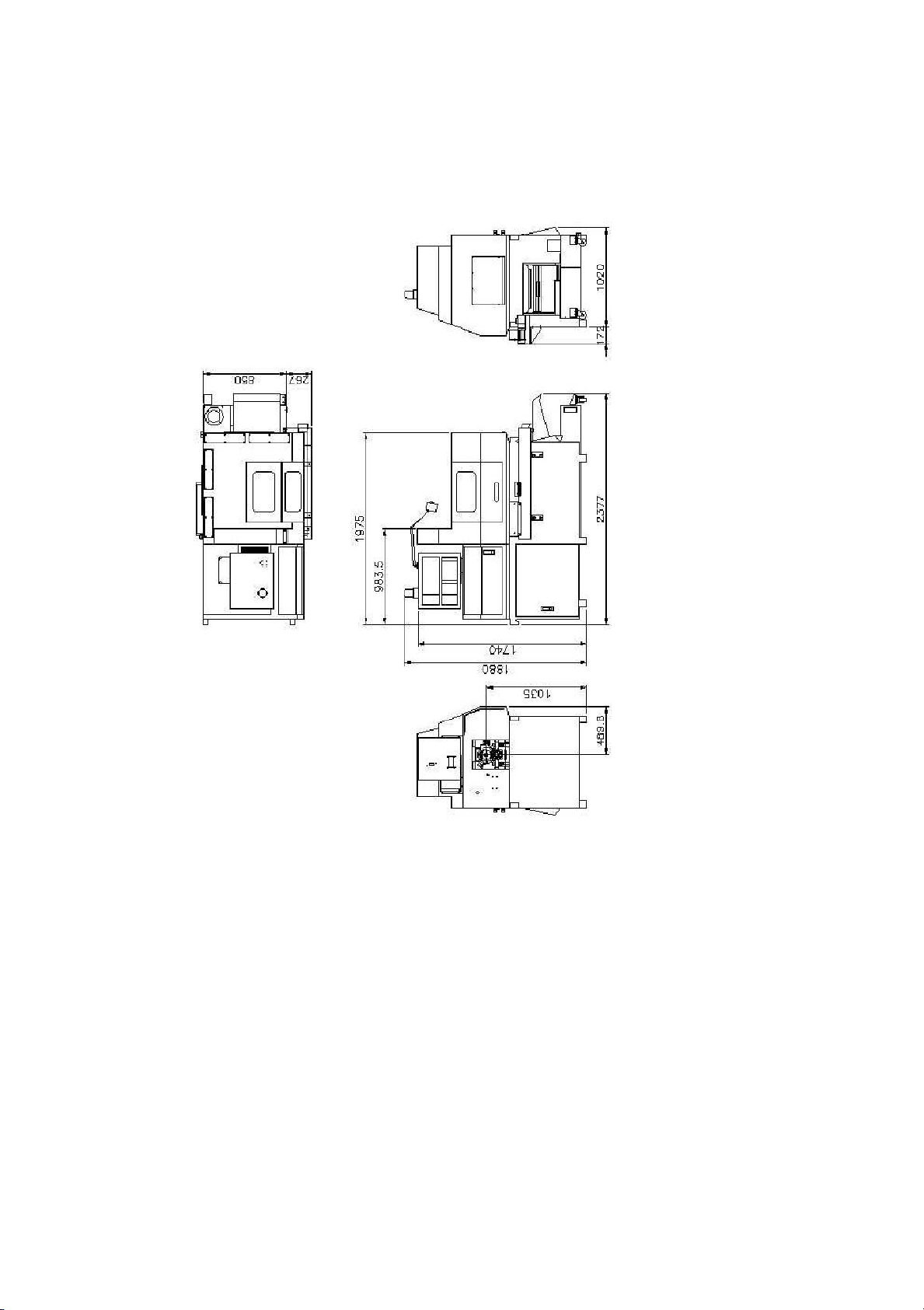
2.3 MACHINE DIMENSION
MACHINE DIMENSION JSL-20AB/B)
2-9
Page 26
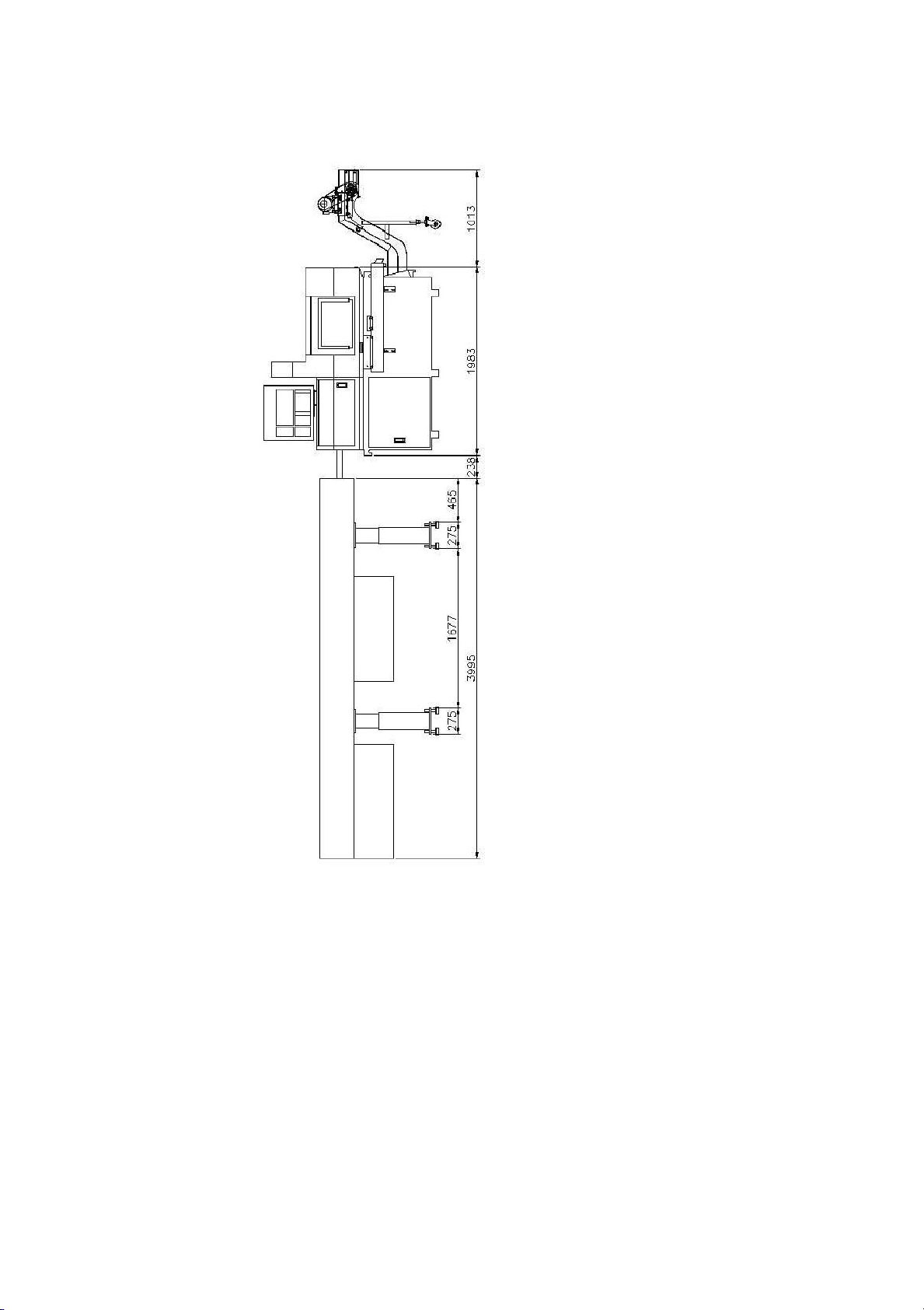
MACHINE DIMENSION -2 (JSL-20AB/B)
2-10
Page 27
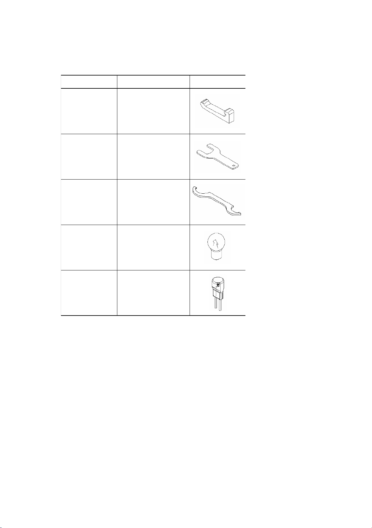
2.4 TOOLS SYSTEM
2.4.1 Consumption Parts List
Part Number Description Picture
20AS180D Gripper
20AS320C
Wrench for cover of collect
chuck holder
20AS370A
Wrench for collect chuck
holder nut
M02080024 Lamp 12V8W
M02080044 Working light lamp 24V50W
2-11
Page 28
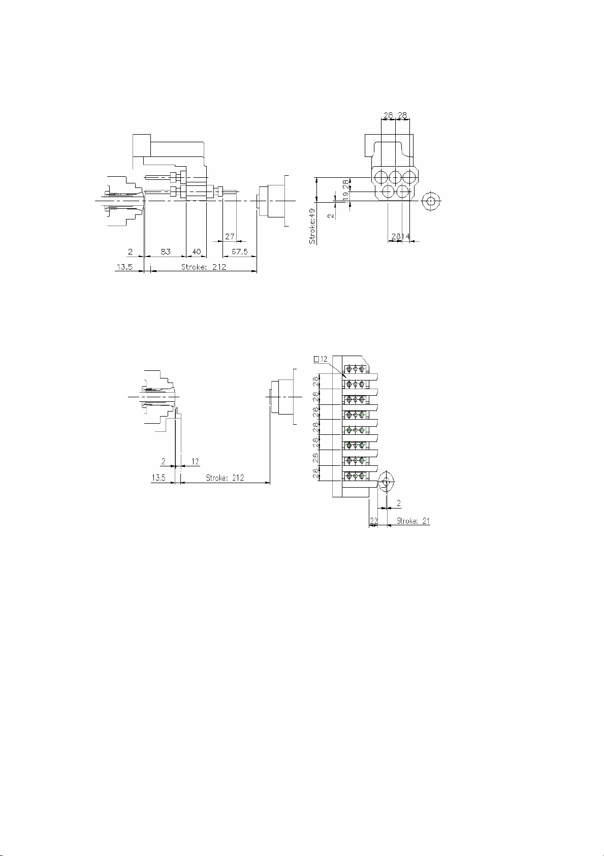
2.4.2 TOOL SYSTEM OVERVIEW
MAIN/SUB SPINDLE AND I.D. TOOL HOLDER SYSTEM(JSL-20AB/B)
MAIN/SUB SPINDLE AND O.D. TOOL HOLDER SYSTEM
2-12
Page 29
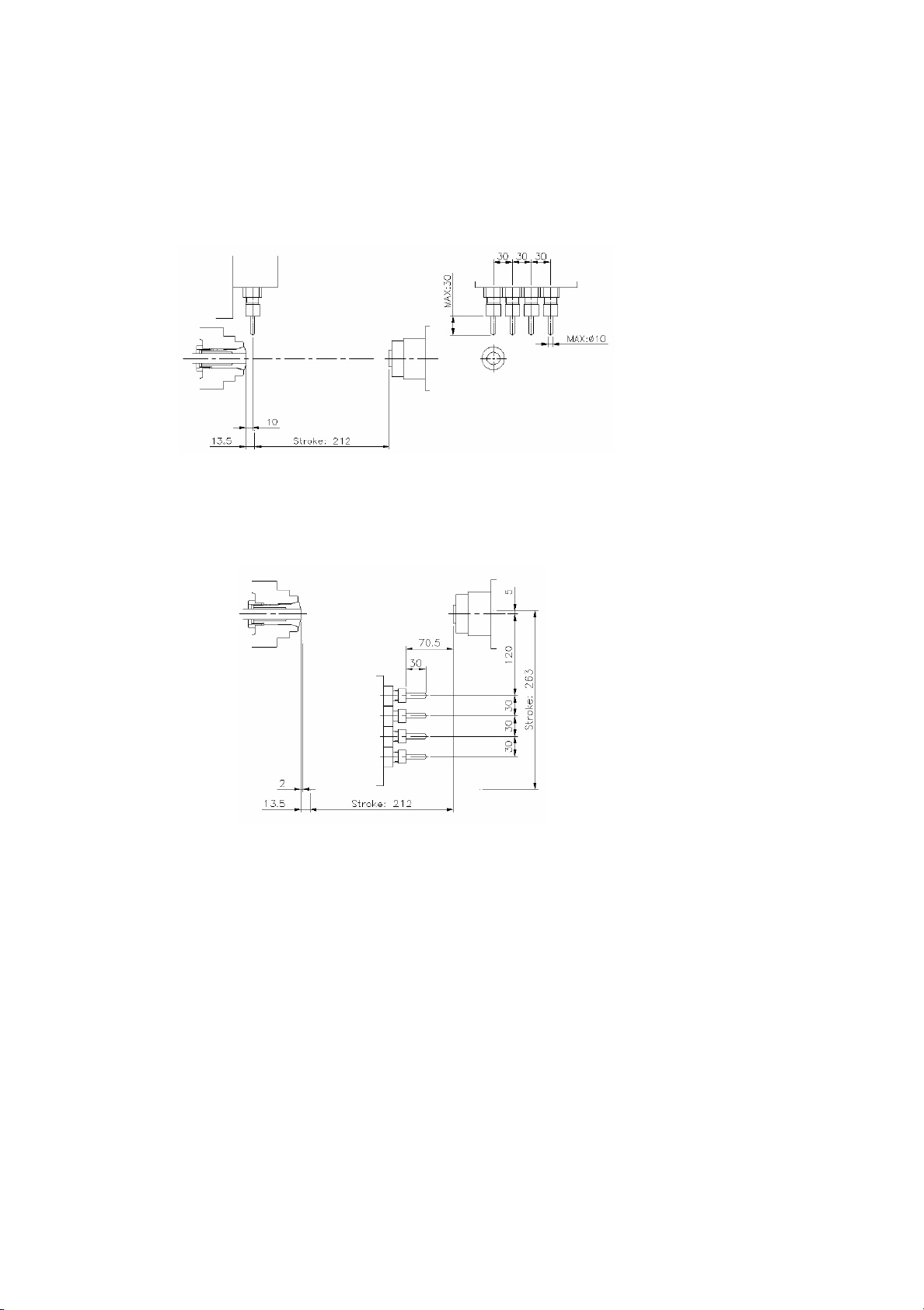
MAIN SPINDLE AND SIDE DRILLING DEVICE(JSL-20AB/B)
SUB SPINDLE AND FACE DRILLING DEVICE(JSL-20AB)
2-13
Page 30
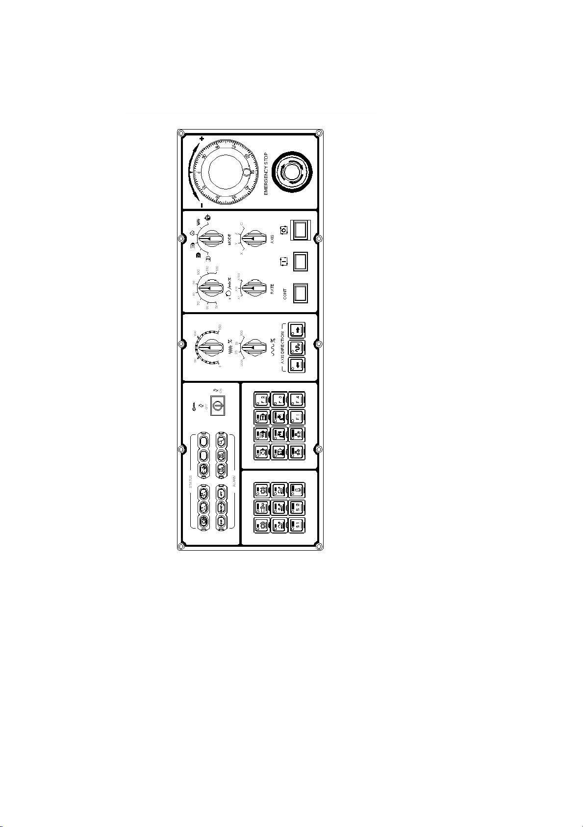
3 OPERATION AND PANEL INSTRUCTION
3.1 OPERATION PANEL INSTRUCTION
OPERATION PANEL
3-1
Page 31
3-2
Page 32

FUNCTION CODE
3-3
Page 33
3-4
Page 34
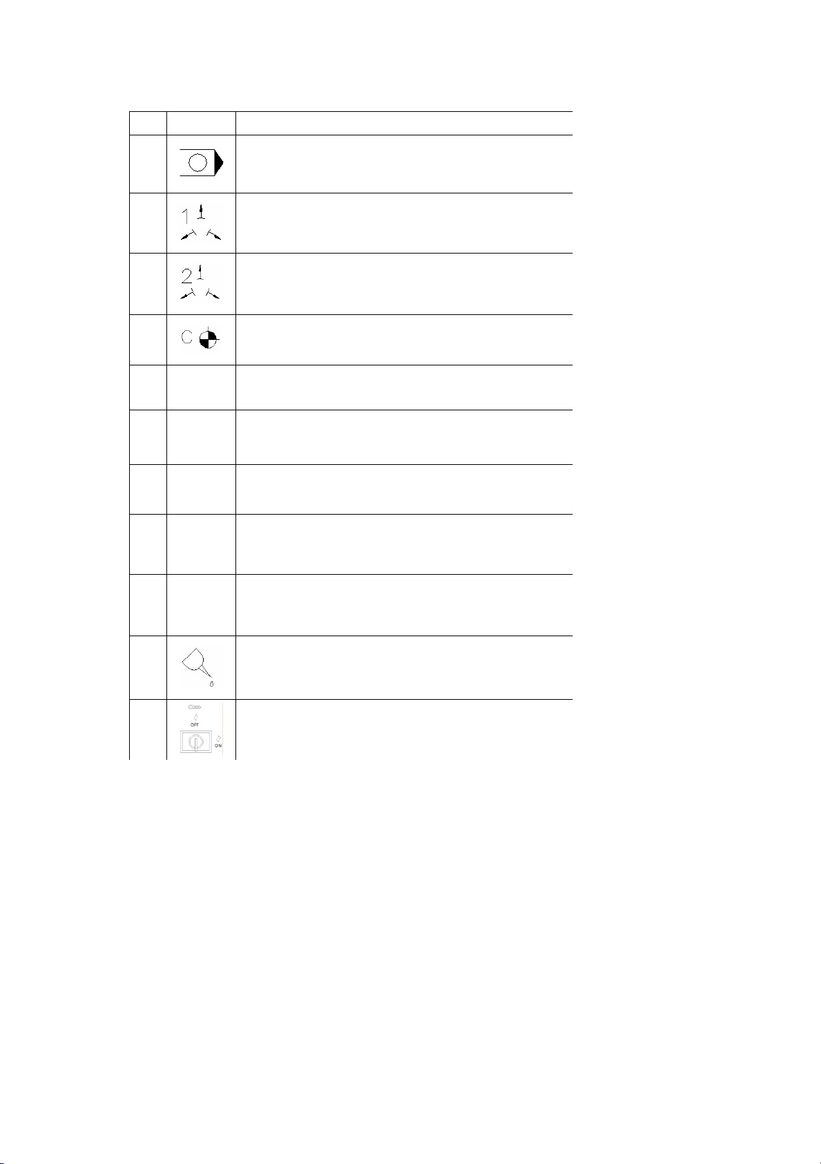
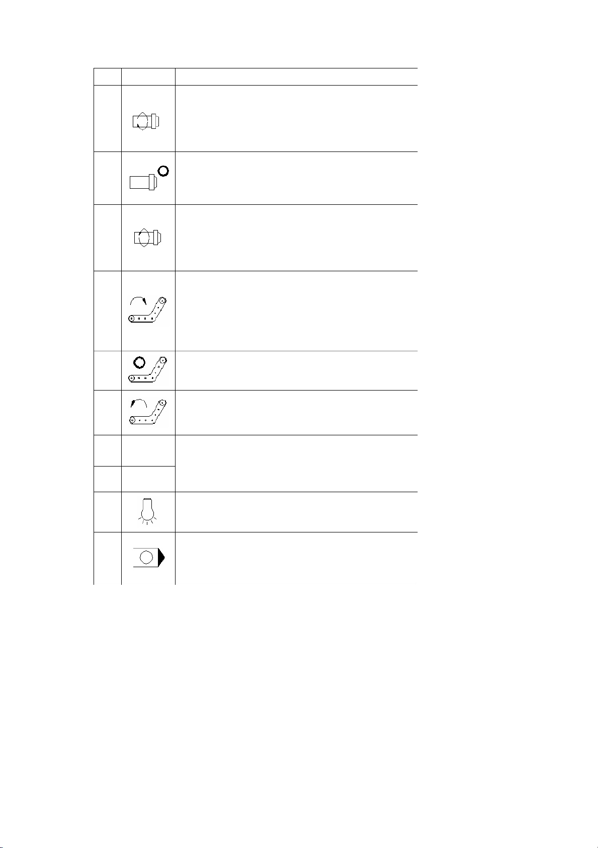
FUNCTION INSTRUCTION
NO. SYMBOL D E S C R I P T I O N
1
END OF PROGRAM INDICATOR:
PROGRAM EXECUTION FINISHED(M30) WHILE LIGHT ON
MAIN SPINDLE CHUCK OPEN/CLOSE:
2 LIGHT ON:CHUCK OPEN
LIGHT OFF: CHUCK CLOSE
SUB SPINDLE CHUCK OPEN/CLOSE:
LIGHT ON:CHUCK OPEN3
LIGHT OFF: CHUCK CLOSE
C AXIS REFERENCE POINT INDICATOR:
4
LIGHT ON: C AXIS RETURNS HOME POINT FINISHED.
5 BAR
BAR FEEDER INDICATOR:
LIGHT ON: BAR FEEDER FUNCTIONIS ACTIVE (K5.3=1).
6 READY
MACHINE READY INDICATOR:
LIGHT ON: MACHINE IS READY TO RUN.
LIGHT OFF: MACHINE MALFUNCTION
3-5
7 APF
AUTOMATIC POWER OFF INDICATOR:
LIGHT ON: APF FUNCTION IS ACTIVE(K3.3)
8
NC CONTROLLER ALARM INDICATOR:
ALM LIGHT ON: CONTROLLER ALARM HAPPENED.
9
MC
ALM
MACHINE ALARM INDICATOR:
LIGHT ON:MACHINE ALARM HAPPENED.
10
LUBRICATION INDICATOR:
LIGHT ON: PLEASE REFILL THE LUBRICATION OIL.
PROGRAM EDIT LOCK FUNCTION:
11 SWITCH KEY TO RIGHT SIDE TO UNLOCK.SWITCH KEY
TO LEFT SIDE TO LOCK(K3.6).
Page 35
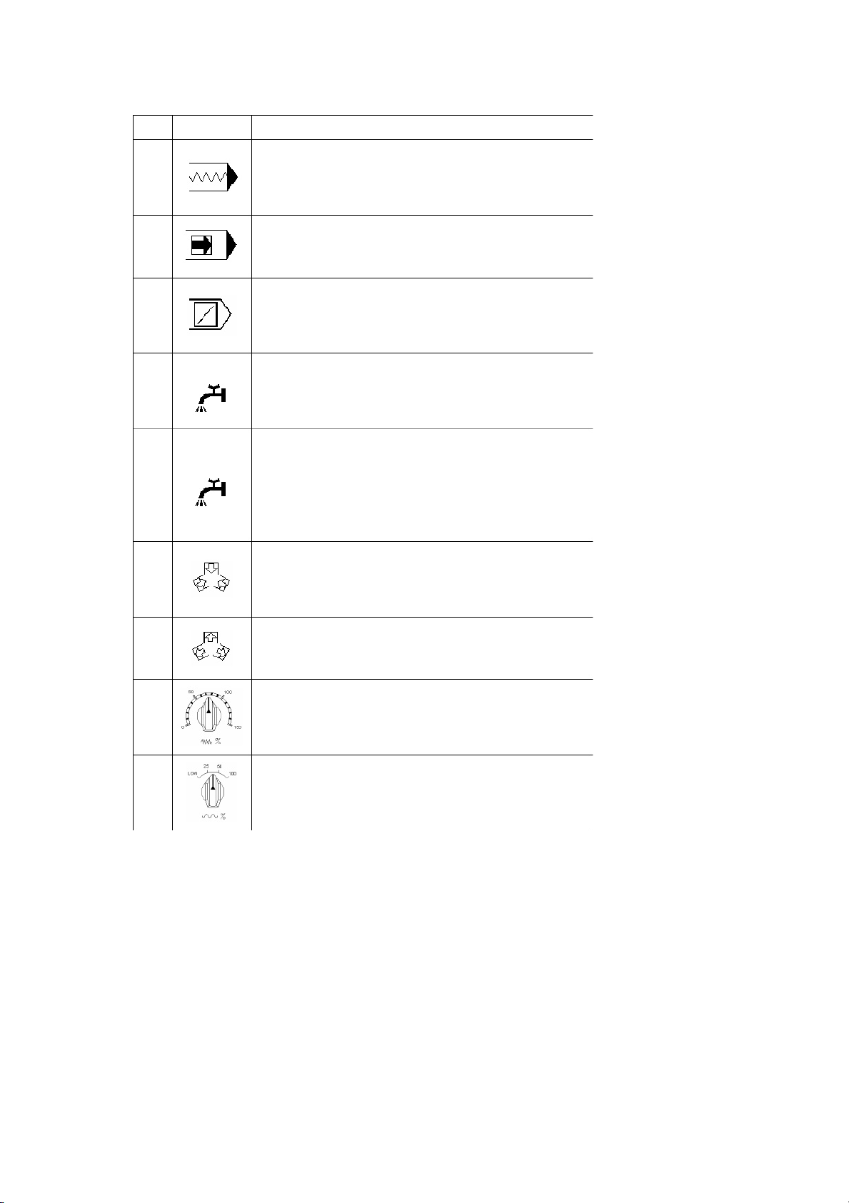
NO. SYMBOL D E S C R I P T I O N
12
SPINDLE CW:
UNDER MPG OR JOG MODE, PRESS THE BOTTOM TO
COMMAND SPINDLE CW 1000RPMAND LIGHT ON.
UNDER MDI OR AUTO MODE,LIGHT IS ON WHEN
SPINDLE CW.
13
SPINDLE STOP:
LIGHT ON:SPINDLE STOP
UNDER MPG MODE AND PRESS THE BOTTOM, SPINDLE
WILL BE FORCED TOSTOP.
14
SPINDLE CCW:
UNDER MPG OR JOG MODE, PRESS THE BOTTOM TO
COMMAND SPINDLE CW 1000RPMAND LIGHT ON.
UNDER MDI OR AUTO MODE,LIGHT IS ON WHEN
SPINDLE CCW.
CHIP CONVEYOR RUN CW:
UNDER MPG OR JOG MODE, PRESS THE BOTTOM WILL
ACTIVE CHIP CONVEYOR RUN CW DIRECTION AND
LIGHT ON.UNDER AUTO MODE, LIGHT WILL BLINK AND
CHIP CONVEYOR WILL RUN CW DIRECTION AND THEN
START/STOP ITSELF DEPENDS ON THE TIMER SETTING.
15
CHIP CONVEYOR STOP:
16 LIGHT ON: CHIP CONVEYOR STOP.
PRESS IT TO STOP THE CHIP CONVEYOR RUNNING.
CHIP CONVEYOR RUN CCW:
UNDER MPG MODE, HOLD THE BOTTOM TO MAKE CHIP
CONVEYOR RUN CCW DIRECTION.
17
18 S 1
19 S 2
SYSTEM SWITCH:S1 MEANS CONTROL SYSTEM1 ONLY.
S2 MEANS CONTROL SYSTEM2 ONLY
PRESS S1 AND S2 AT THE SAM TIME MEANS CONTROL
BOTH SYSTEMS.
20
WORK LIGHT:
PRESS THE BOTTOM TO TURN ON THE LIGHT.
21
OPTIONAL STOP:PRESS THE BOTTOM AND LIGHT ON.
WHEN PROGRAM RUN M01, SYSTEM WILL PAUSE UNTIL
PRESS THE BOTTOM AGAIN.WHEN LUBRICATION INDICATOR
IS ON, SYSTEM WILL ENABLE THIS FUNCTION ITSELF.
3-6
Page 36
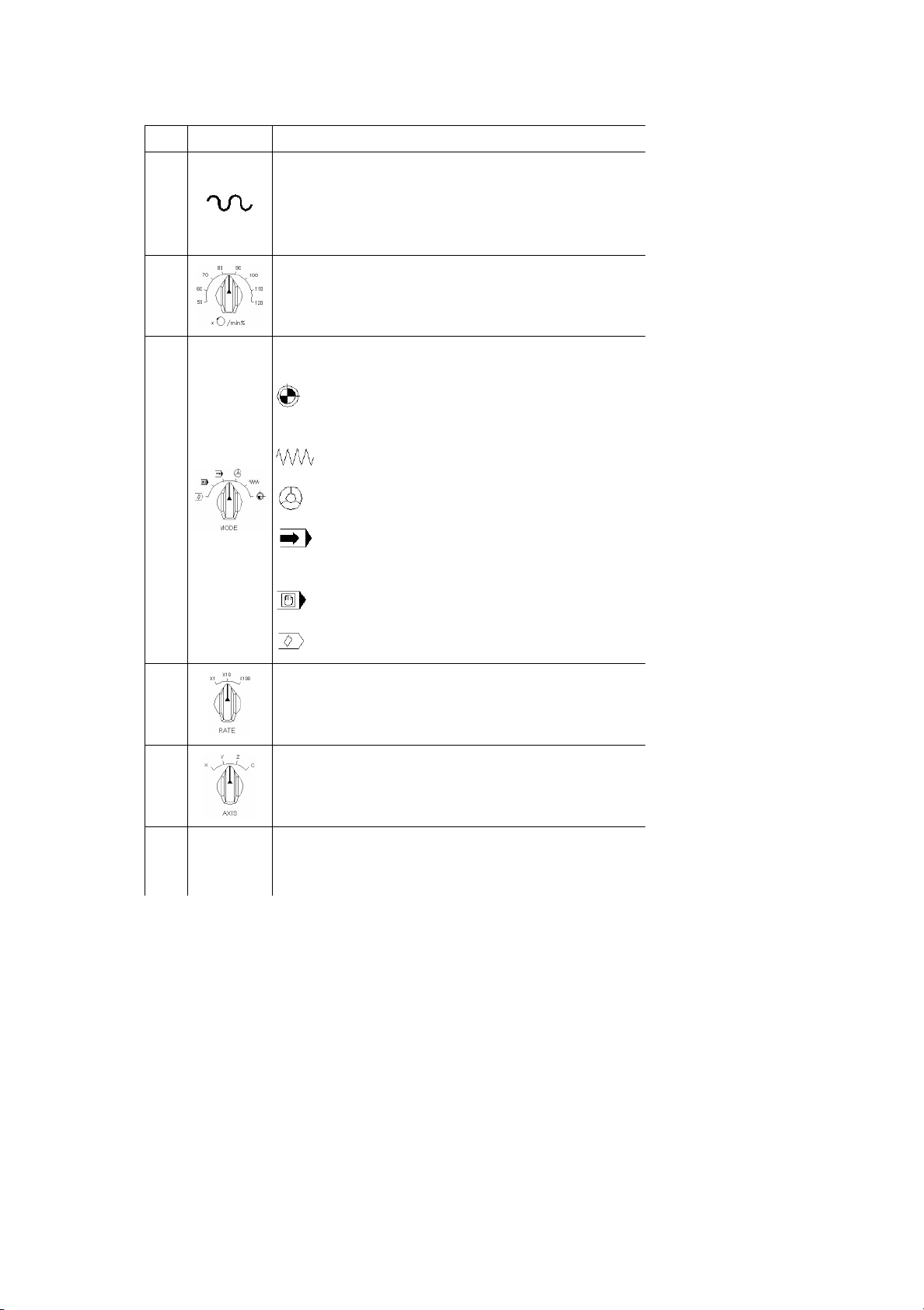
NO. SYMBOL D E S C R I P T I O N
22
DRY RUN:
PRESS THE BOTTOM AND LIGHT ON.WHEN PROGRAM
IS RUNNING, IT MOVES SLOWLY.THE SPEED DEPENDS
ON G01 FEEDRATE.
23
SINGLE BLOCK:
PRESS THE BOTTOM AND LIGHT ON.
SYSTEM WILL RUN NC PROGRAM BLOCK BY BLOCK.
24
BLOCK BYPASS:
PRESS THE BOTTOM AN LIGHT ON.
WHEN SYSTEM MEETS THE SYMBOL(/),IT WILL BYPASS
THE BLOCK.
25
AUTO
AUTO COOLANT OIL:
PRESS THE BOTTOM WHEN SYSTEM MEETS M08 OR
M13,IT WILL TURN ON THE COOLANT PUMP.
MANUAL COOLANT OIL:
26
MANU SWITCH TO SYSTEM 1 TO ACTIVE COOLANT OIL FOR
SYSTEM 1 ONLY.AND THE LIGHT WILL BLINK.
SWITCH TO SYSTEM 2 OR UNDER AUTO MODE .IT WILL
ACTIVE COOLANT OIL FOR SYSTEM 2 ONLY.AND THE
LIGHT ON.
27
RELEASE CHUCK AIR PRESSURE:
IT IS TO ADJUST THE PRESSURE BETWEEN COLLET
CHUCK AND BAR.WITH SYSTEM SWITCH FUNCTION TO
ADJUST SYSTEM1 OR SYSTEM2.
28
CHUCK OPEN/CLOSE:
LIGHT OFF:CHUCK CLOSE
LIGHT BLINK: CHUCK OPEN.
G01FEEDRATE KNOB:
ROTATE THE KNOB TO CHANGE G01 FEEDRATE.
29
30
G01FEEDRATE KNOB :
ROTATE THE KNOB TO CHANGE G01 FEEDRATE.
3-7
Page 37
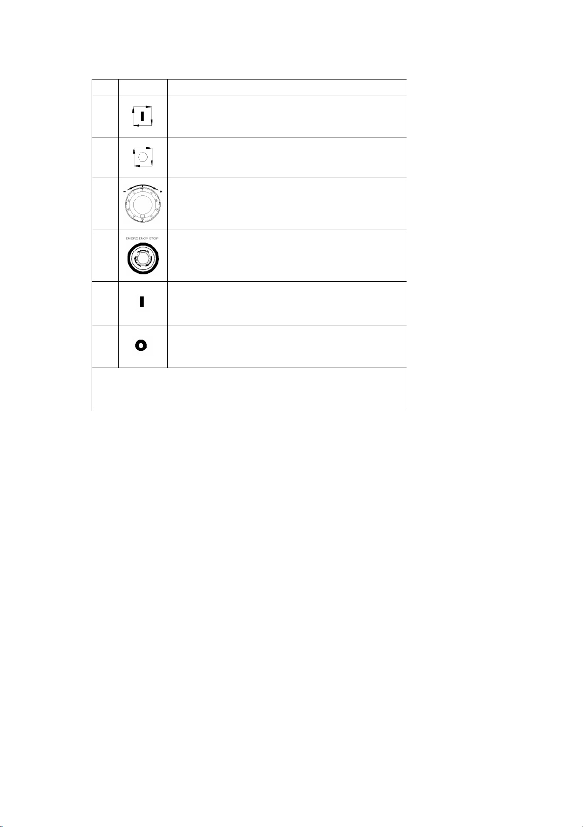
NO. SYMBOL D E S C R I P T I O N
AXIS KNOB:
UNDER JOG MODE, SWITCH TO MOVE ANY AXIS TO+/-
DIRECTION.31
WHEN MACHINE IS RUNNING, THE AXIS LIGHT WILL
ONDEPENDS ON THE RUNNING AXIS.
32
SPINDLE SPEED RATE KNOB:
ROTATE THE KNOB TO CHANGE THE SPPED RATE OF
SPINDLE.
MODE SELECTION KNOB:
ROTATE THE KNOB TO CHANGE MODE
HOME:PRESS +DIRECTION BOTTOM TO BACK TO
REFERENCE POINT.
JOG:PRESS AXIS BOTTOM TO MOVE THE AXIS。
MPG:USE MPG TO MOVE THE AXIS.
33
AUTO:PRESS CYCLE START TO RUN THE NC
PROGRAM.
MDI:FOR TESTING OR CALL TOOL.
EDIT:EDIT NC PRORAMS.
34
MPG SPPED RATE KNOB:
SELECT THE RATE TO CHANGE THE MPG FEEDRATE.
THE UNIT:Hx1:0.001mm、Hx10:0.01mm、Hx100:0.1mm
。
35
AXIS SELECTION KNOB:
ROTATE THE KNOB TO SELECT THE AXIS.
PROGRAM RECYCLE:
36 CONT PRESS THE BOTTOM AND LIGHT ON.WHEN SYSTEM
MEETS M30.IT WILL RESTART THE NC PROGRAM.
3-8
Page 38
NO. SYMBOL D E S C R I P T I O N
CYCLE START:
37 UNDER AUTO MODE, PRESS THE BOTTOM TO START
RUNNING NC PROGRAM.
38
FEED HOLD:
WHILE PROGRAM IS RUNNING,PRESS THE BOTTOM
TO HOLD THE PROGRAM.
39
MPG:
UNDER MPG MODE, ROTATE MPG TO MOVE THE AXIS.
EMERGENCY STOP:
40 PRESS THE BOTTOM TO STOP ALL MOVEMENT.ROTATE
THE HEAD TO RELEASE THE EMERGENCY STOP.
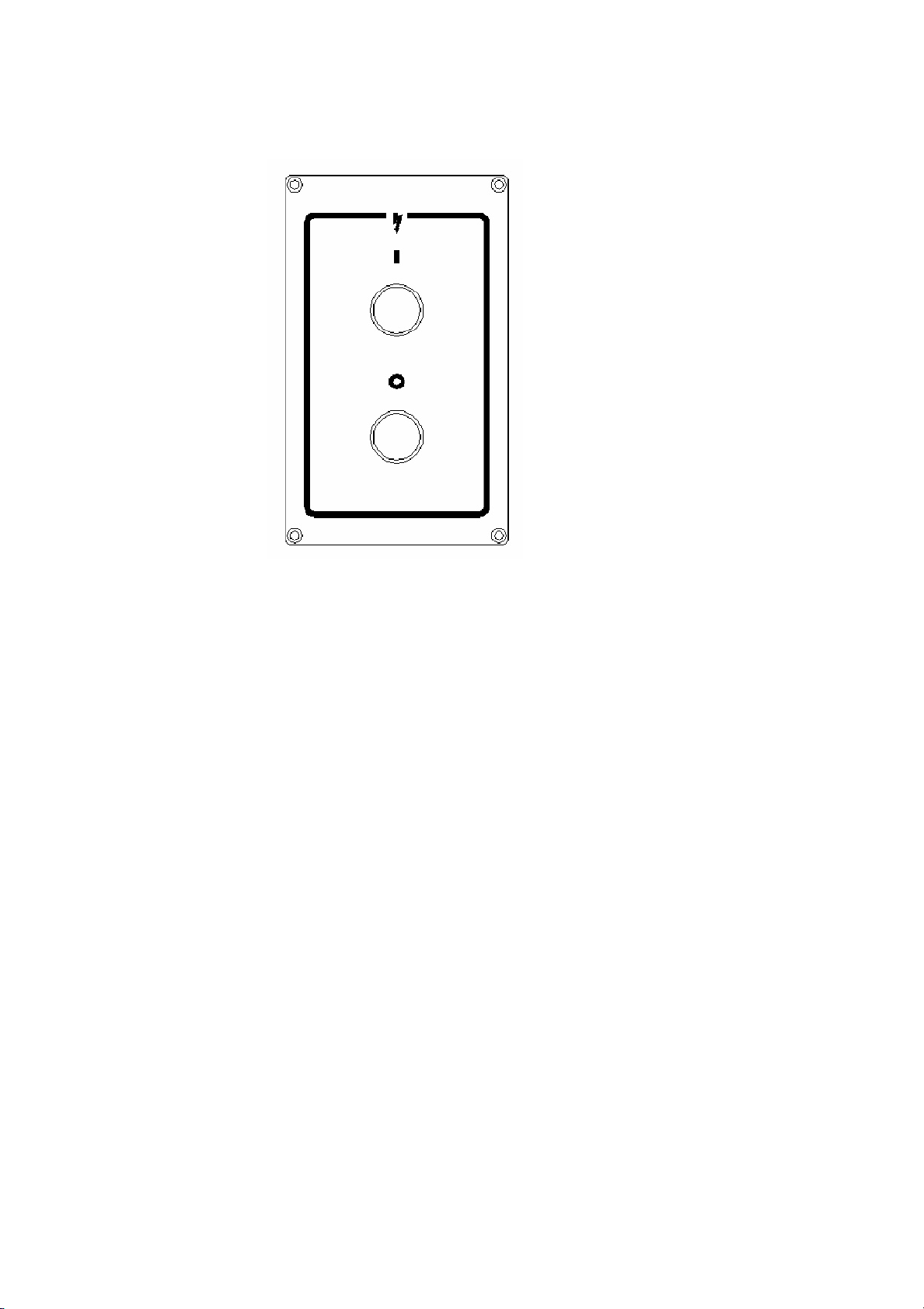
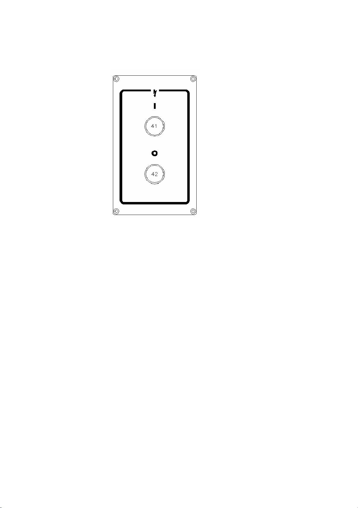
41
POWER ON:
PRESS THE BOTTOM TO TURN ON THE POWER.
POWER OFF:
42
PRESS THE BOTTOM TO TUEN OFF THE POWER.
SPACE AND F1、F2、F3、F4 HAVE NO FUNCTION.
3-9
Page 39
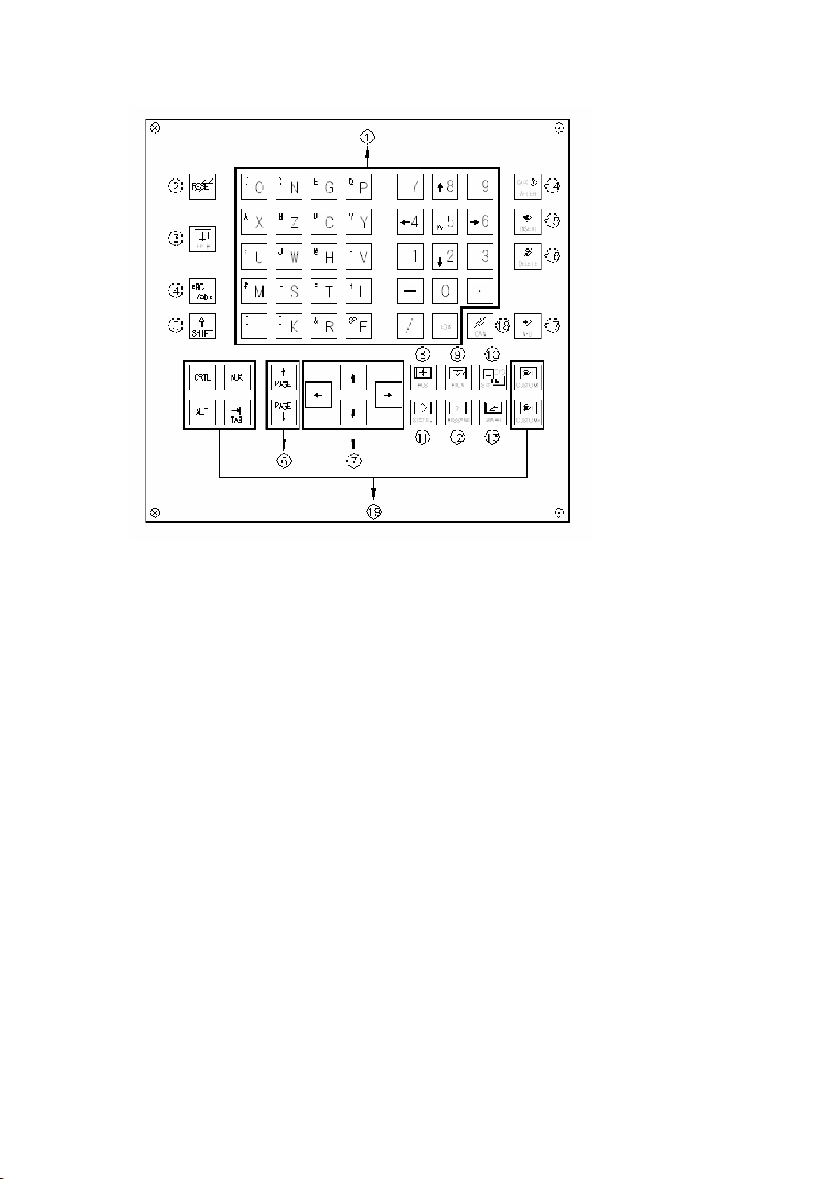
3.2 FANUC 32i PANEL INSTRUCTION
3-10
Page 40

FUNCTION KEY INSTRUCION
NO D E S C R I P T I O N
1
WORDS AND NUMBERS:
It includes A~Z 0~9 and other symbols. Some are compound buttons and use
SHIFT to switch caption.
2
RESET:
Release alarm message and reset CNC system.
3
HELP:
Helps the user to know the meanings of alarm messages, programming, and
parameter descriptions, etc...
4
ABC/abc:
Switches between capital and lowercase for English words.
5
SHIFT:
Switches between buttons with two functions.
6
PAGE↑↓:
Use to scroll up and down the screen.
7
←↑↓→:
Move the cursor on the screen.
8
POS:
Display the position of each axis, including abs/rel/machine position.
9
PROG:
Display the program for editing and monitoring.
OFS/SET:
10 Use for setting tool length, compensation value, working piece count, time/date,
etc…
11
SYSTEM:
Use to set system parameters, diagnostic parameters, PLC information and
etc…
3-11
Page 41

NO D E S C R I P T I O N
12
MESSAGE:
For checking CNC and machine alarm messages.
13
GRAPH:
Displays tool and cutting path.
ALTER:
14
Use to modify the words on the screen.
15
INSERT:
Use to insert words which have been edited at the bottom of the screen into the
program which displayed on the screen.
16
DELETE:
Use to delete words on the screen under EDIT MODE.
INPUT:
17
Use to input all values on the screen.
18
CAN:
Use to cancel the words at the bottom of the screen.
19 Other buttons are not available
3-12
Page 42

3-13
3.3 G CODE LIST
CODE DESCRIPTION
G00 Positioning (Rapid traverse)
G01 Linear interpolation (Cutting feed)
G02 Circular interpolation CW
G03 Circular interpolation CCW
G04 Dwell
G12.1 Polar coordinate interpolation mode
G13.1 Polar coordinate interpolation cancel mode
G17 Xp Yp plane selection
G18 Zp Xp plane selection
G19 Yp Zp plane selection
G28 Return to reference position
G30 2ndreference position return
G32 Thread cutting
G40 Tool nose radius compensation cancel
G41 Tool nose radius compensation left
G42 Tool nose radius compensation right
Coordinate system setting
G50
Max. spindle speed setting
G70 Finishing cycle
G71 Stock removal in turning
G72 Stock removal in facing
G73 Pattern repeating
G74 End face peck drilling
G75 Outer diameter/internal diameter drilling
G76 Multiple threading cycle
G80 Canned cycle for drilling cancel
G83 Cycle for face drilling
G84 Cycle for face tapping
G90 Outer diameter/internal diameter cutting cycle
G92 Thread cutting cycle
G96 Constant surface speed control
G97 Constant surface speed control cancel
G98 Per minute feed
G99 Per revolution feed
G188 Main system X-axis side rigid tapping
G284 Sub system Z-axis end face tapping
G300 Return to program reference point
Page 43

3-14
3.4 M CODE LIST FOR MAIN SYSTEM
CODE DESCRIPTION
M00 Program stop
M01 Optional program stop
M02 End of program
M03 Spindle CW
M04 Spindle CCW
M05 Spindle stop
M08 Coolant oil
M09 Coolant oil cancel
M10 Spindle chuck close
M11 Spindle chuck open
M13 Spindle CW+ coolant oil
M14 Spindle CCW+ coolant oil cancel
M24 Spindle air blow on
M25 Spindle air blow off
M29 Spindle rigid tapping
M30 End of program
M32 Cut off detection
M34 Threading 45° back off
M35 Threading 90° back off
M38 C axis mode
M39 C axis mode cancel
M42 Cut-off tool turning head of bar automatically
M60 Bar feeder pressure on
M61 Bar feeder pressure off
M62 Allow bar feeder feeding back off
M63 Confirm bar change finished
M81 Positioning check mode
M82 Positioning check mode cancel
M88 X axis mirror mode
M89 X axis mirror mode cancel
M91 Change bar and turning head of bar sub-program (Turning type)
M92 Change bar and turning head of bar sub-program (Swiss type)
M95 Single block bypass mode
M96 Single block bypass mode cancel
M113 Side/Face drilling CW
M114 Side/Face drilling CCW
M115 Side/Face drilling stop
Page 44

3-15
M123 Main system end face drilling CW
M125 Main system end face drilling stop
M133 Main/Sub spindle synchronous CW
M134 Main/Sub spindle synchronous CCW
M135 Main/Sub spindle synchronous stop
M140 Main/Sub X axis synchronous running
M141 Main/Sub X axis synchronous running cancel
M142 Main/Sub Z axis synchronous running
M143 Main/Sub Z axis synchronous running cancel
M144 Main/Sub C axis synchronous running
M145 Main/Sub C axis synchronous running cancel
M300 Spindle orientation 0°
M301 Spindle orientation 15°
M302 Spindle orientation 30°
M303 Spindle orientation 45°
M304 Spindle orientation 60°
M305 Spindle orientation 75°
M306 Spindle orientation 90°
M307 Spindle orientation 105°
M308 Spindle orientation 120°
M309 Spindle orientation 135°
M310 Spindle orientation 150°
M311 Spindle orientation 165°
M312 Spindle orientation 180°
M313 Spindle orientation 195°
M314 Spindle orientation 210°
M315 Spindle orientation 225°
M316 Spindle orientation 240°
M317 Spindle orientation 255°
M318 Spindle orientation 270°
M319 Spindle orientation 285°
M320 Spindle orientation 300°
M321 Spindle orientation 315°
M322 Spindle orientation 330°
M323 Spindle orientation 345°
M1000~M1100
Main/Sub system Waiting command (Refer to CH3.11)
Page 45

3-16
3.5 M CODE LIST FOR SUB SYSTEM
CODE DESCRIPTION
M00 Program stop
M01 Optional program stop
M02 End of program
M03 Spindle CW
M04 Spindle CCW
M05 Spindle stop
M08 Coolant oil
M09 Coolant oil cancel
M10 Spindle chuck close
M11 Spindle chuck open
M13 Spindle CW+ coolant oil
M14 Spindle CCW+ coolant oil cancel
M18 Parts conveyor active
M24 Spindle air blow on
M25 Spindle air blow off
M29 Spindle rigid tapping
M30 End of program
M33 Ejecting parts detection
M34 Threading 45° back-off
M35 Threading 90° back-off
M38 C axis mode
M39 C axis mode cancel
M81 Positioning check mode
M82 Positioning check mode cancel
M113 Side/Face drilling CW
M114 Side/Face drilling CCW
M115 Side/Face drilling stop
M1000~M1100
Main/Sub system Waiting command (Refer to CH3.11)
Page 46

3-17
3.6 JSL-20AB PARAMETER K SERIES
Addres
Description
Addres
Description
K0.0 Coolant oil pressure detection K4.0
K0.1 Parts conveyor active K4.1
K0.2 Mirror function enable K4.2
K0.3 K4.3
K0.4 M11=spindle jog while using bar K4.4
Selection of Lubrication oil level detection
K0.5 K4.5 Parts count function disable
K0.6 K4.6 Chuck detection SENSOR enable
K0.7 K4.7
K1.0 CE Safety interlock door function K5.0 Chuck detection SENSOR disable
K1.1 K5.1
K1.2 K5.2
K1.3 K5.3 Connecting bar feeder(K5.2 = 0)
K1.4 K5.4
K1.5 K5.5
K1.6 K5.6 Spindle lock disable but
K1.7 K5.7
K2.0 K6.0 Call T16—T18 tool function enable
K2.1 K6.1 Call T25—T27 tool function enable
K2.2 Chip conveyor disable K6.2 PMC axis MPG enable
K2.3
Chip conveyor running without controlled
K6.3
K2.4 K6.4
K2.5
Solenoid valve detecting function for
K6.5
K2.6 K6.6
K2.7 K6.7
K3.0 K7.0
K3.1 K7.1
K3.2 K7.2
K3.3 Automatic power off enable K7.3
K3.4 K7.4
K3.5 Air pressure detection enable K7.5
K3.6 Data protection lock disable K7.6
K3.7 K7.7
Page 47

3-18
Addres
Description
Addres
Description
K8.0 K12.0
Only Main system A1 MPG enable, others
disable
K8.1 K12.1
K8.2 K12.2
K8.3 K12.3
K8.4 K12.4
K8.5 K12.5
K8.6 Sub spindle air blow simultaneously K12.6
K8.7 K12.7
K9.0 K13.0
K9.1 K13.1
K9.2 K13.2
K9.3 K13.3
K9.4 K13.4
K9.5 K13.5
K9.6 K13.6
K9.7 K13.7
K10.0 K14.0
K10.1 K14.1
K10.2 K14.2
K10.3 K14.3
K10.4 K14.4
K10.5 K14.5
K10.6 K14.6
K10.7 K14.7
K11.0 K15.0
K11.1 K15.1
K11.2 K15.2
K11.3 K15.3
K11.4 K15.4
K11.5 K15.5
K11.6 K15.6
K11.7 K15.7
Page 48

3-19
3.7 JSL-20AB PARAMETER D SERIES
NO ADDRESS PARMETER TYPE DATA
1 D0 00000000 2 100
2 D400 00000000 1 40
3 D480 00000010 1 10
4 D500 00000010 2 75
5 D800 00000010 1 50
6 D900 00000010 0 100
7 D1000 00000000 2 100
8 D2500 00000010 2 75
9 D2800 00000010 1 50
D address Description Value Remark
D0500 #1 M300 Spindle positioning angle 0
D0504 #1 M301 Spindle positioning angle 15
D0508 #1 M302 Spindle positioning angle 30
D0512 #1 M303 Spindle positioning angle 45
D0516 #1 M304 Spindle positioning angle 60
D0520 #1 M305 Spindle positioning angle 75
D0524 #1 M306 Spindle positioning angle 90
D0528 #1 M307 Spindle positioning angle 105
D0532 #1 M308 Spindle positioning angle 120
D0536 #1 M309 Spindle positioning angle 135
D0540 #1 M310 Spindle positioning angle 150
D0544 #1 M311 Spindle positioning angle 165
D0548 #1 M312 Spindle positioning angle 180
D0552 #1 M313 Spindle positioning angle 195
D0556 #1 M314 Spindle positioning angle 210
D0560 #1 M315 Spindle positioning angle 225
D0564 #1 M316 Spindle positioning angle 240
D0568 #1 M317 Spindle positioning angle 255
D0572 #1 M318 Spindle positioning angle 270
D0576 #1 M319 Spindle positioning angle 285
D0580 #1 M320 Spindle positioning angle 300
D0584 #1 M321 Spindle positioning angle 315
D0588 #1 M322 Spindle positioning angle 330
D0592 #1 M323 Spindle positioning angle 345
D0596
Page 49

3-20
D address Description Value Remark
D0620 Side drilling gear ratio (multiply by value) 375
D0624 Side drilling gear ratio (divide by value) 256
D0628 Side drilling max. speed 4000
D0632 Face drilling gear ratio (multiply by value) 625
D0636 Face drilling gear ratio (divide by value) 273
D0640 Face drilling max. speed 4000
D0644 Side drilling tool side gear ratio 3
D0648 Side drilling motor side gear ratio 4
D0656 Side drilling motor side gear ratio 5
D0660 Side drilling motor side gear ratio 8
D0800 #1 Manual stop spindle 0
D0802 #1 JOG mode for control spindle speed 51
D0804 #1 Manual control spindle speed to 500RPM 256
D0806 #1 Manual control spindle speed to 600RPM 307
D0807 #1 Manual control spindle speed to 700RPM 358
D0810 #1 Manual control spindle speed to 800RPM 410
D0812 #1 Manual control spindle speed to 900RPM 461
D0814 #1 Manual control spindle speed to 1000RPM 512
D0816 #1 Manual control spindle speed to 1100RPM 563
D0818 #1 Manual control spindle speed to 1200RPM 614
D1200 #1 G300 reference point(1st Z axis positive limit -
D1204 #1 G300 reference point (2nd Z axis positive limit -
D1208 #1 G300 reference point (3rd Z axis positive limit -
D1212 #1 3rdZ axis positive limit
D1216 #1 3rdZ axis negative limit
D2804 #2 Manual control spindle speed to 500RPM 137
D2806 #2 Manual control spindle speed to 600RPM 164
D2808 #2 Manual control spindle speed to 700RPM 191
D2810 #2 Manual control spindle speed to 800RPM 218
D2812 #2 Manual control spindle speed to 900RPM 246
D2814 #2 Manual control spindle speed to 1000RPM 273
D2816 #2 Manual control spindle speed to 1100RPM 300
D2818 #2 Manual control spindle speed to 1200RPM 328
Page 50
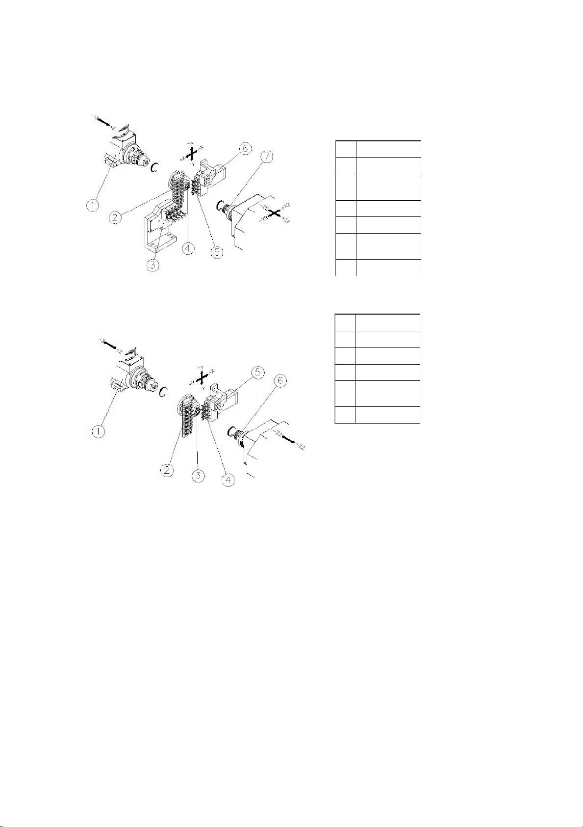
3.8 MACHINE MOVEMENT INSTRUCTION
THIS IS THE MACHINE WITH A BUILD-IN SLIDING HEAD SPINDLE. THE MAIN
MECHANICAL STRUCTURE IS AS SHOWN IN THE FOLLOWING DIAGRAMS.
DESCRIPTION
1 MAIN SPINDLE
2 TOOL HOLDER
SUB SPINDLE
3
SIDE DRILLING
4 GUIDE BUSHING
5 SIDE DRILLING
6
INNER TOOL
HOLDER
7 SUB SPINDLE
JSL-20AB
DESCRIPTION
1 MAIN SINDLE
2 TOOL HOLDER
3 GUIDE BUSHING
4 SIDE DRILLING
INNER TOOL
HOLDER
5
6 SUB SPINDLE
JSL-20B
3-21
Page 51
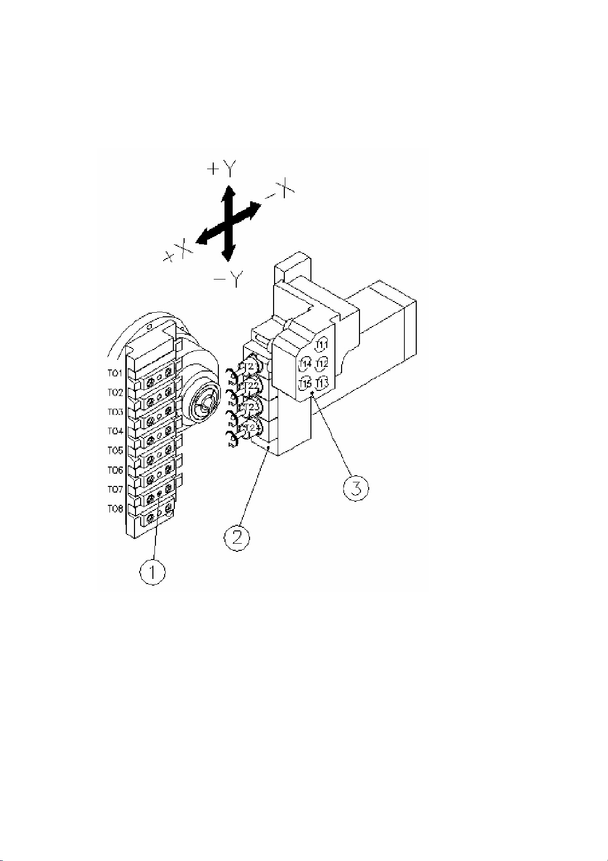
MAIN SPINDLE AND TOOL SYSTEM
X, Y, and Z-axis are controlled by the CNC controller and the work is done by the
spindle with bar and tool system. There are three main devices of the main system:(1)
Tool Holder 、(2)Drill Tool Holder 、(3)Side Drill Device
Install tools on the tool holder for O.D. turning. Install twist drill into the tool holder for face
drilling, tapping, horning, and etc…
3-22
Page 52
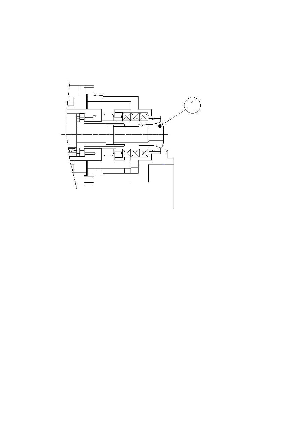
GUIDE BUSHING HOLDER
To hold the bar at the nearest place of the turning point, it prevents deformation by
cutting and keeps high accuracy. The loading of O.D. cutting is as shown in the following
diagram. Figure(1)The accuracy depends on the distance between the guide bushing
holder and bar. Therefore, please use high O.D. accuracy bar.(refer to CH 1.3)
3-23
Page 53
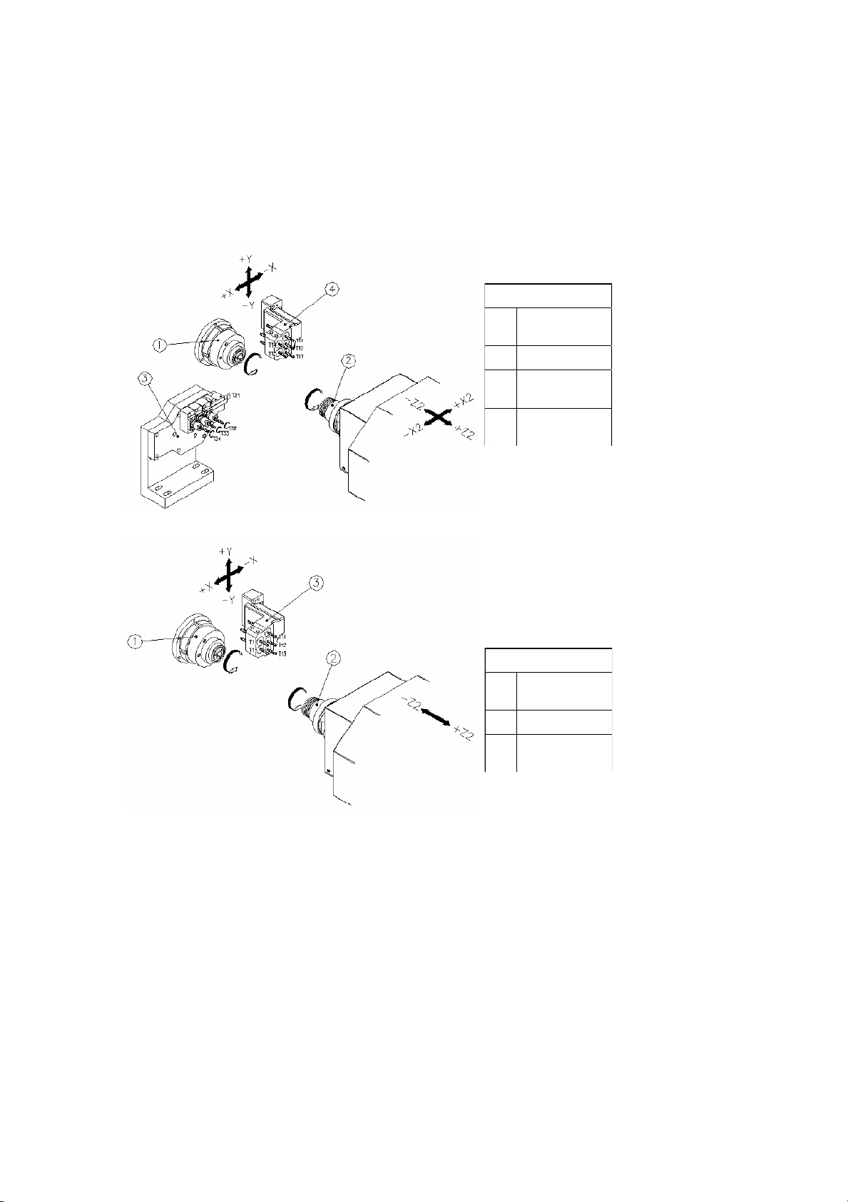
SUB SPINDLE AND TOOL SYSTEM (JSL-20AB/B)
Sub spindle is controlled by X2 and Z2-axis.。
While turning backside, the working piece is moved by Z2-axis and tool selection by
X2-axis movements. The functions of sub system are as follows:
1. End face turning, grooving
2. Z and Z2-axes move synchronously
3. Backside turning
*TOOL NO. T31 CAN INSTALL □12 O.D. TURNING TOOL.
DESCRIPTION
GUIDE
BUSHING
1
2 SUB SPINDLE
3
SUB SPINDLE
SIDE DRILLING
FACE
DRILLING
4
JSL-20AB SUB SPINDLE AND TOOL SYSTEM
DESCRIPTION
GUIDE
BUSHING
1
2 SUB SPINDLE
3
FACE
DRILLING
JSL-20B SUB SPINDLE AND TOOL SYSTEM
3-24
Page 54
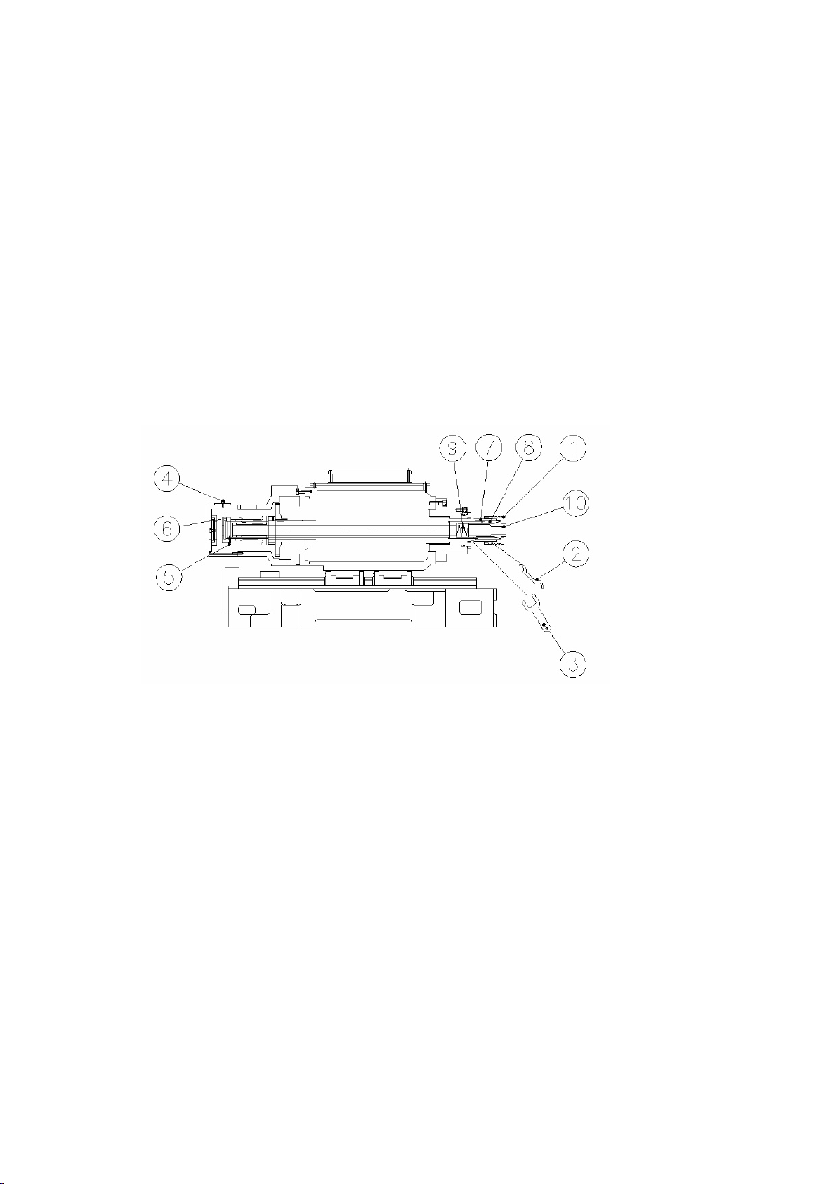
3.9 MACHINE SETTING AND ADJUSTMENT
COLLET CHUCK INSTALLATION AND ADJUSTMENT
A. INSTALLATION
1. Put collet chuck sleeve⑧ nto spindle. The key way of sleeve must match the key
inside the spindle ⑦.
2. Put the collet chuck spring⑨and collet chuck⑩ into the sleeve.
3. Use the wrench②&③in CCW direction to screw the nut①until it is tight.
B. ADJUSTMENT
1. The step to adjust the pressure of collet chuck
2. Take out the screw④.
3. Use 3mm hexagon wrench to release the two M6 screws⑤of the gripper
adjusting nut.
4. Put a 4mm hexagon wrench into the ψ5 hole⑥of the nut and put the wrench③
to hold the head of the spindle. Rotate CW direction to tighten the pressure of collet
chuck. Rotate CCW to release the pressure of collet chuck.
5. Testing: Use 80% hand force to move the pressure pushing shank to test the
pressure of collet chuck. The machine will not work if it is too tight. If too loose it can
not hold the bar.(To change the gripper, please refer to page 3-34).
3-25
Page 55
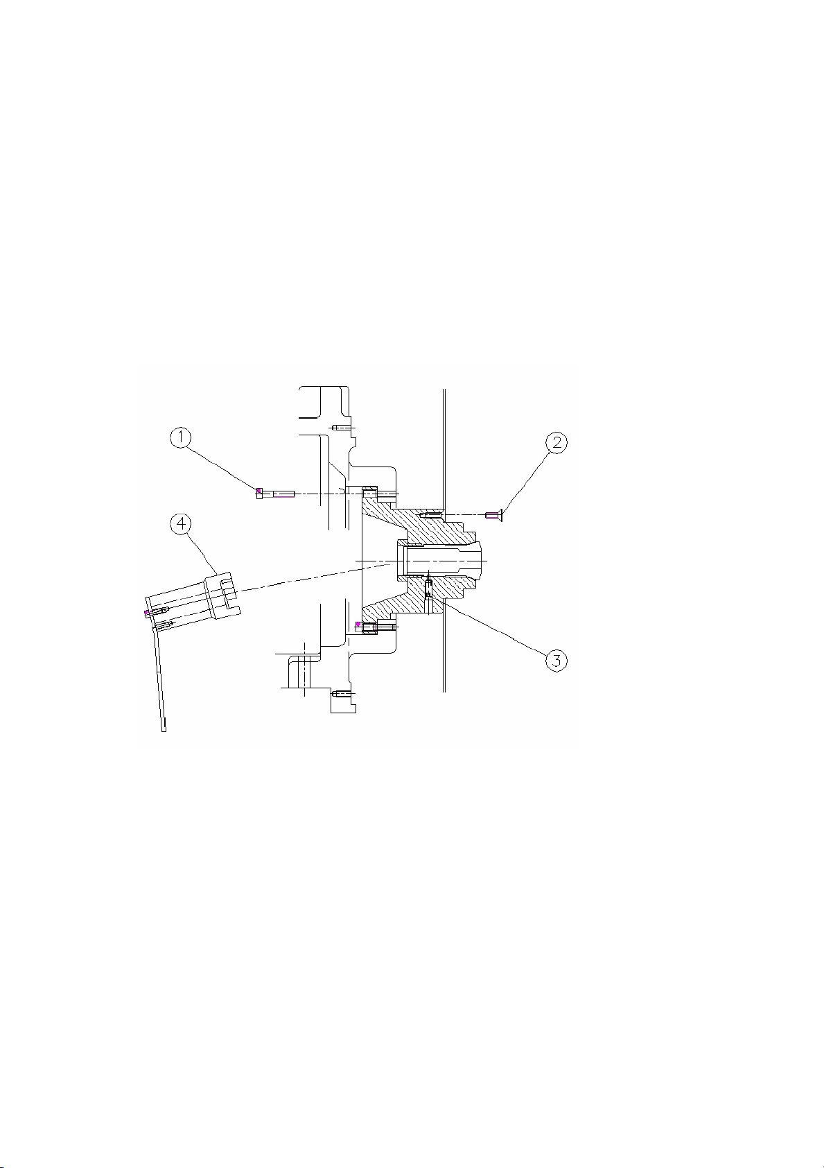
GUIDE BUSHING HOLDER INSTALLATION AND ADJUSTMENT
The JSL-20AB has three turning models, a fixed guide bush holder, a traveling
guide bush holder, and a turning type. You need to change the mounting device
and parameters while changing to a different guide bush holder, please use
following steps.
zz
Mounting Device
(A) Use six M6x25L HEX SOCKET CAP SCREWS (①) mounting guide bush
holder on spindle.
(B) Use six M6x25L HEX SOCKET CAP SCREWS (②) mounting guide bush
holder on spindle.
(C) Please note that the fixing bolt must be under the guide bush holder (③),
please check with the following diagram
(D) Use wrench (④) to screw tight and adjust the tightness between the bar
and guide bush holder. Finished.
(E) Change parameters (Refer to Ch.3.10) and test travel distance.
3-26
Page 56
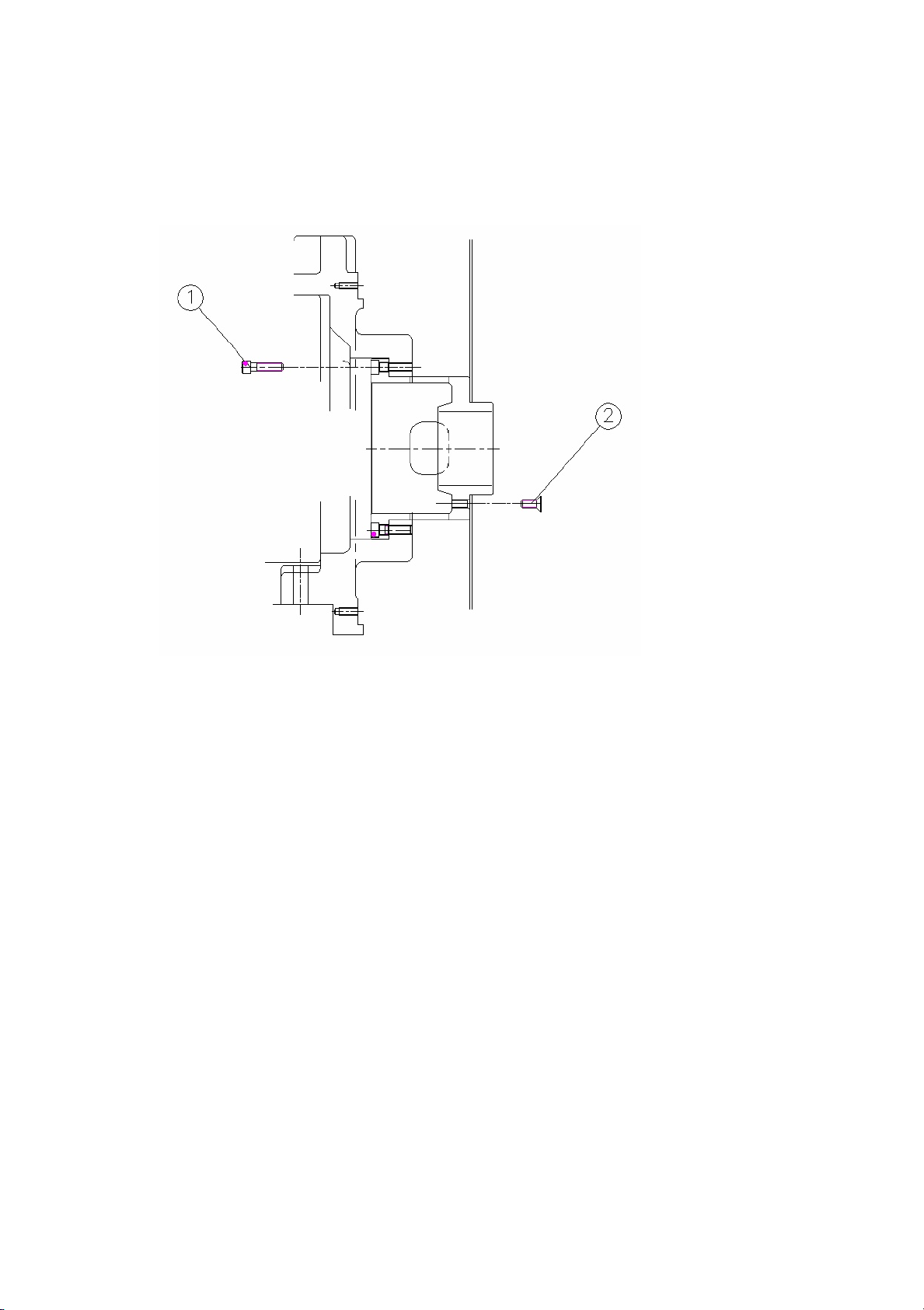
TRAVELING GUIDE BUSH HOLDER
Use six M6x20L HEX SOCKET CAP SCREWS (①) mounting guide bush holder on
spindle. Use three M6X12L PAN HEAD HEX SOCKET CAP SCREWS (②) to fix on
sheet metal. Change parameters and test travel distance.
3-27
Page 57
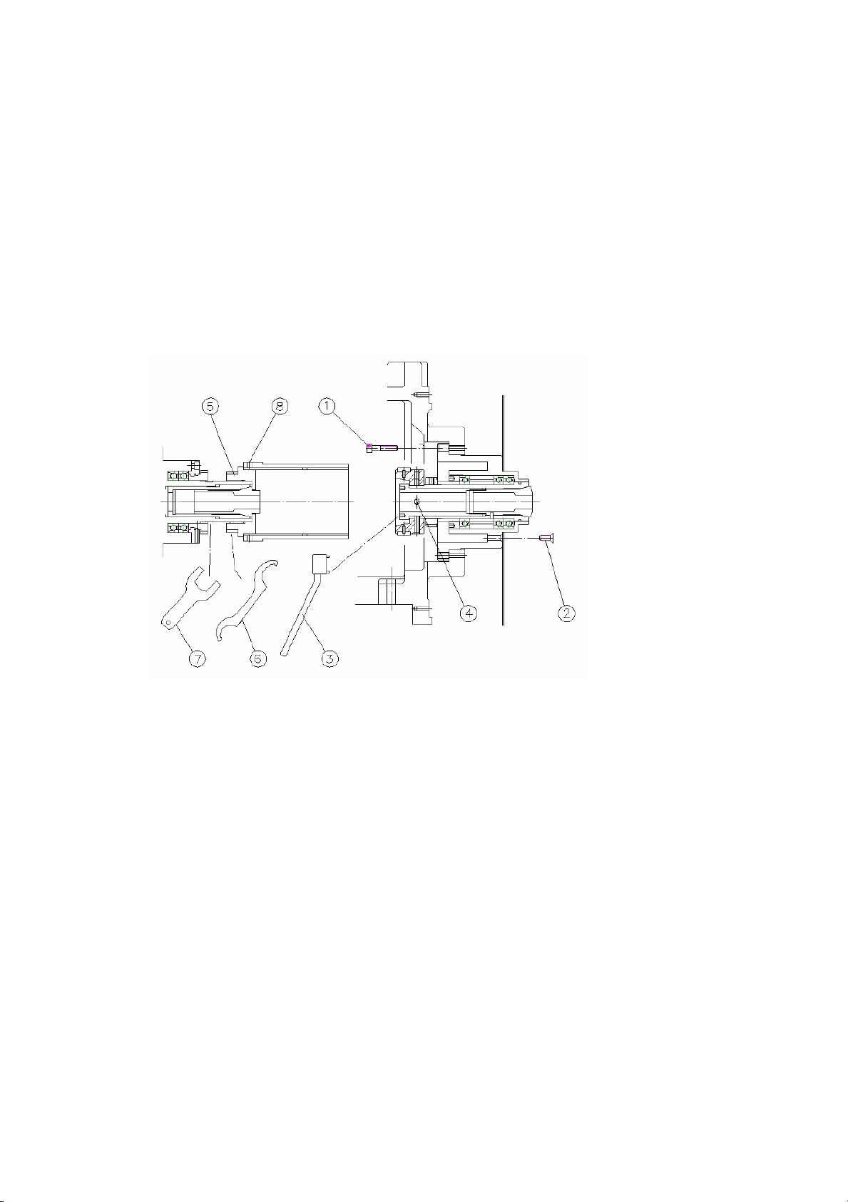
SIMUTANEOUS ROTATING GUIDE BUSH HOLDER
Install the connecting device to connect the traveling guide bush holder with cover, and
then tighten the side screws of collect chuck cover.
1. Use six M6x25L HEX SOCKET CAP SCREWS(①) mounting guide bush
holder on spindle
2. Use three M6X12L PAN HEAD HEX SOCKET CAP SCREWS (②) to fix on
sheet metal.
3. Use tool ⑥&⑦to change cover of spindle collect chuck to cover of collect
chuck for traveling guide bush holder (⑤)
4. Adjust the distance and tightness between the guide bush holder and bar,
then use the 3mm hexagonal wrench to tighten the side screws (④).
5. Install the sleeve between traveling guide bush holder and collect chuck
holder cover. Screw it tight. (⑧)
Switch the parameters (Refer to CH3.10) and test traveling distance.
COLLET CHUCK OF SUB SPINDLE INSTALLATION AND ADJUSTMENT
Before install collet chuck into sub spindle, please take out the back side cover of sub
spindle. The following steps are the same as main spindle.
3-28
Page 58
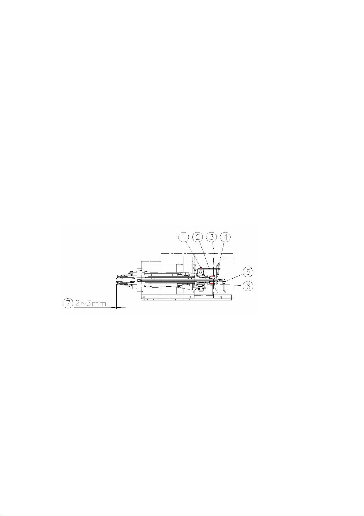
EJECT PART DEVICE INSTRUCTION
The size of eject part device depends on the part diameter. (Refer to Fig. 2)
The diameter of eject part device is smaller 1.0mm than I.D. of collet chuck.
(Refer to Fig 3- ①)
The steps to change the eject part device;
1. Take out the back side cover of sub spindle. (Fig.1-③)
2. Take out the screw (Fig.1-①) and then take out the (Fig.1-②)
3. Take out the M14 nut and actuator of eject part device sensor. Please see
(Fig.1-④)
4. Take out the screw of holder of eject part device (Fig.1-⑥) and take out the
pusher rod of eject part device from the back side of sub spindle.
5. After changing the pusher, follow the step 4->3->2->1 to finish the installation.
NOTE:
1. The correct position of actuator of eject part device sensor and M14 nut should be
at the edge of pneumatic cylinder. The head of the eject part device should over the
plane of collet chuck 2~3mm.
2. As shown in Fig. 2, the actuator of eject part device sensor should active the
proximity sensor, and the actuator should parallel with sensor and keep distance
within 2~3mm.
3. Please refer to Fig 3 to make the pusher of the eject part device. The size of
Fig.3-①has to be modified by the size of part.
4. The length for part into the spindle should not exceed 70mm, or the mechanical
parts will be damaged.
FIGURE 1
3-29
Page 59
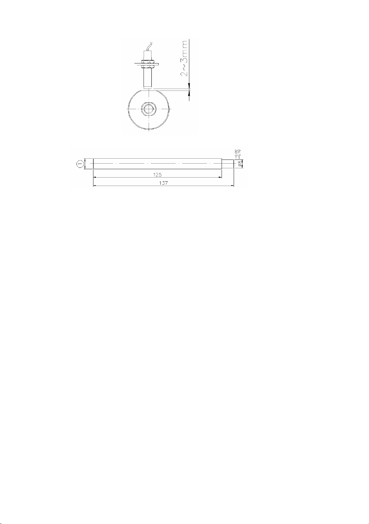
FIGURE 2
FIGURE 3
3-30
Page 60
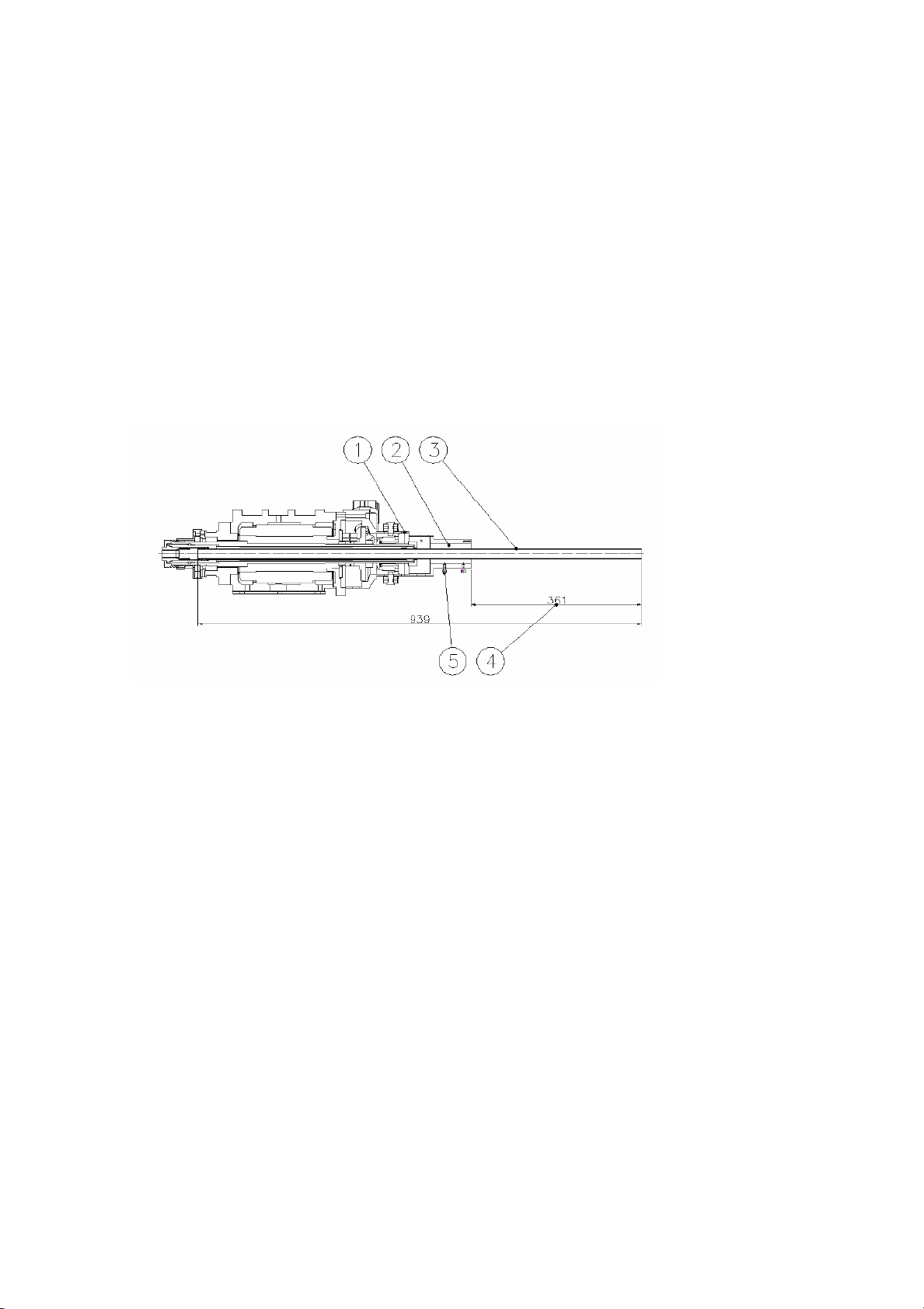
LONG PARTS CATCHER (OPTIONAL ACCESSORY)
1. INSTALLATION
A. Hold tight the collet chuck, and then use M5X30 Screw to install the mounting device
on the back side of sub spindle.
B. Put the holder (Fig.1-②) into the long parts catcher (Fig.1-③), and together installed
on the mounting device. At the moment, please check the length of long parts catcher
should be 361mm (Fig.1-④).
C. Screw M5 tight (Fig.1-⑤), and make sure the long parts catcher is fixed on the
mounting device.
2. NOTICE
A. Please refer to Fig. 2 to make the tube of long parts catcher. The max diameter is
20mm, and the max. I.D. of sub spindle is 22mm.
B. The size of long parts catcher depends on the size of parts , and parts should not end
lap inside the tube.
C. Please refer to Fig. 3 to learn how to make the holder.
FIGURE 1
3-31
Page 61
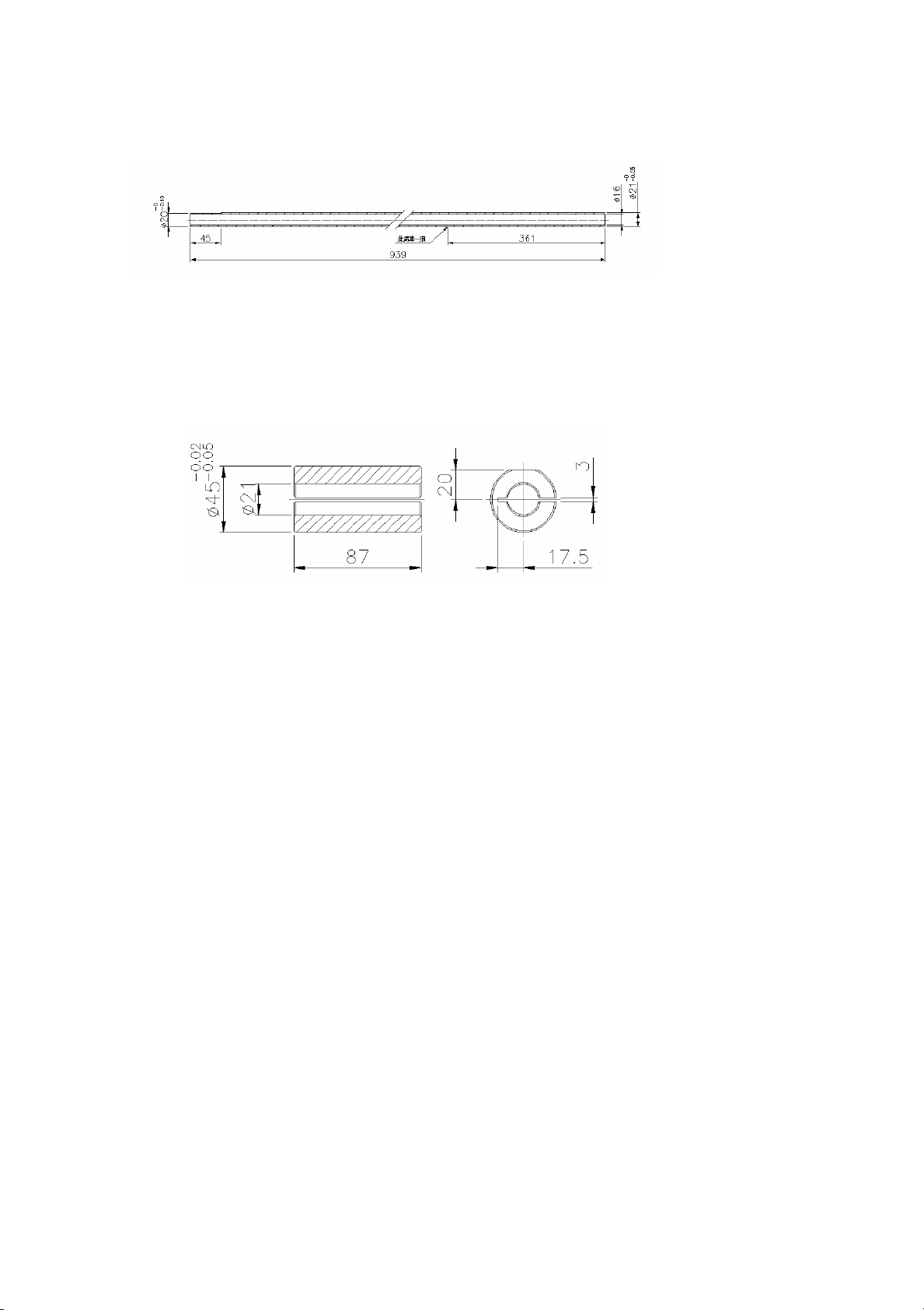
FIGURE 2
FIGURE 3
3-32
Page 62

CHANGE GRIPPER
zz
REMOVE GRIPPER
1. Remove nut of collect chuck holder and take out collect chuck holder and sleeve.
2. Remove water proof cover (Fig.1-①)
3. Use the 3mm hexagon wrench to remove the nut (Fig.1-②) of adjusting gripper
4. Release the screw (Fig.1-⑦) at the side of the gripper shank, and take out the rod
(Fig.1-④) above the shank (Fig.1-③).
NOTE: Both up and down have one screw.
5.Remove screw (Fig.1-⑧), and separate the Y connector from gripper shank, and
take out the cylinder.
NOTE: Switch to MPG MODE and press the chuck air pressure release before the next
step.
6. Take out the gripper sliding base (Fig.1-⑨), and gripper.
zz
INSTALL GRIPPER
For installing the gripper, reverse the steps of removing the gripper.
Step (6→5→4→3→2→1)
NOTICE
1. If the installation of gripper is correct (Fig.2-①), while open the collet chuck, the tail of
gripper goes up. If not (Fig.2-②), please install the gripper again.
2. Confirm connection between the connector of gripper shank (Fig.3-①) and Y
connector of air cylinder (Fig.3-②). If the gripper does not hook the taper sleeve,
switch to MPG mode and press “RELEASE CHUCK AIR PRESSURE”.
Press chuck OPEN/CLOSE to pull back the air cylinder (Fig.3-④), and use the
pressure pushing shank to move the gripper. It will cause 15mm gap of collet chuck.
After confirm the collet chuck pressure (refer to CH3.9), the ψ12 hole of Y type
connector should between the range while push/pull the pressure pushing
shank.(Fig.4-①).
3-33
Page 63
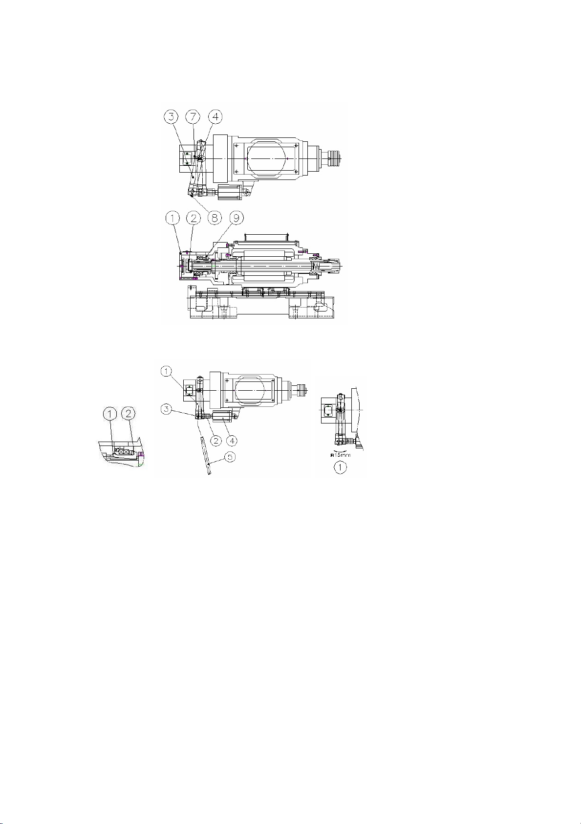
Figure
Figure 2 Figure 3 Figure4
3-34
Page 64

3-35
3.10 SETTING MODE OF GUIDE BUSH HOLDER
There are three modes of guide bush holder for the main spindle of JSL-20AB: the fixed
guide bush holder, traveling guide bush holder and turning type. It is necessary to change
the guide bush holder when changing modes. Besides, each guide bush holder has its
own proper Z-axis travel distance limit. Therefore, change the Z-axis limit mode and guide
bush holder at the same time.
1. Press [OFS/SET] button →[XX]→[OPERAT PANEL]→Screen shown as in below
table.
2. Use [↓] [↑] buttons to change cursor position.
3. Use [←] [→] buttons to change OFF or ON.
4. Square cursor will move by step 3.
OFF ON
T25-VALD
■
CHUCK OF
■
Z LIMIT2
■
Z LIMIT3
■
DOR CANC
■
Note:
1. Use fixed guide bush holder while Z LIMIT2 and Z LIMIT 3 are OFF
2. Use turning type while Z LIMIT2 is ON.
3. Use Traveling guide bush holder while Z LIMIT3 is ON.
4. The alarm will sound while Z LIMIT2 and Z LIMIT3 are ON.
5. While using the traveling guide bush holder and Z-axis OT alarm, press the opposite
axis button and rotate MPG to release OT.
Page 65

3-36
3.11 WAITING M CODE INSTRUCTION
Function: It is used to communicate with main and sub system while machining.
M code range: M1000~M1100
Description:
1. While two systems execute at the same time, running M1000 will ask one system
to wait on the other.
2. When one system is waiting on another system running M1000, run M1000 in the
other system to let srcinal system keep running. At the moment, two systems are
running without waiting.
3. If one system is waiting by running M1000, we want to keep the system running
but ask the other system to wait. Please input M1000 and M1001.
4. Waiting M code is only for one block, and it can not be executed with another
command at the same block.
5. Waiting M code of two systems should answer with each other, and the quantity
of waiting M code of two systems should be the same.
6. System will not be affected by waiting M code, if only one system is executed in
the NC program.
7. Please refer to 3-29 to see example.
Page 66

3-37
M1000~1100 EXAMPLE
Main system Sub system
M05; N1
T0808;( stop material) G28 W0.
M11; M1000 (Wait Main system)
G4 X1.0; G97 M13 S2000 T0101 (Drill)
G300 X-2.0 Z52.0 T0808; G0 X0.
G50 Z0. ; Z1.0
M10; G99 G1 Z-10.0 F0.1
G4 X1.0 ; G0 Z10.0
G0 X25.0 Z-1.0 ; M05
M1000;(Call Sub system) N2
N1 ; T0202 ( Eject component)
G97 M13 S3000 T0606 ;(O.D. TOOL)G0 X0.
G0 X18.0 Z-1.0 ; Z0.
G99 G1 Z50.0 F0.08 ; M11
X20.1 Z52.0 ; G4 X1.0
G0 X22.0 ; M33
M05 ; N3
N2 ; T0303 ( Catch component)
T0808 ; (CUT-OFF TOOL) G28 W0.
M133 S2000 ; M11
G0 X21.0 Z52.0 ; G0 X0.
M1001 ; (Call Sub system) M1001 (Wait main system)
M1002 ; (Wait Sub system) G0 Z0.
G99 G1 X-2.0 F0.04 ; G98G1 Z-20.0 F200
M1003 ; (Call Sub system) M10
M1004 ; (Wait Sub system) G4 X0.5
M135 ; M1002 ( Call main system)
M09 ; M1003 (Wait sub system)
M01 ; G98 G1W3.0 F300
M1005 ;(Wait Sub system) M1004 (Call Main system)
M99 ; G28 W0.
M1005(Call Main system)
M99
Page 67
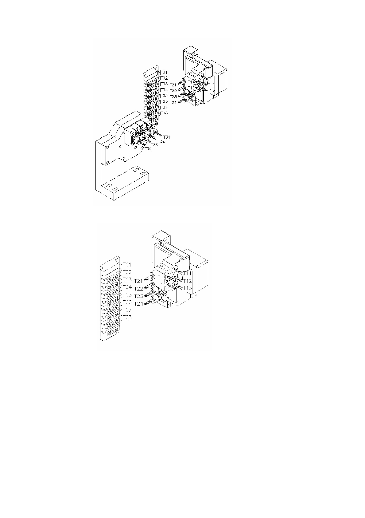
JSL-20AB TOOL NUMBER
JSL-20B TOOL NUMBER
3-38
Page 68
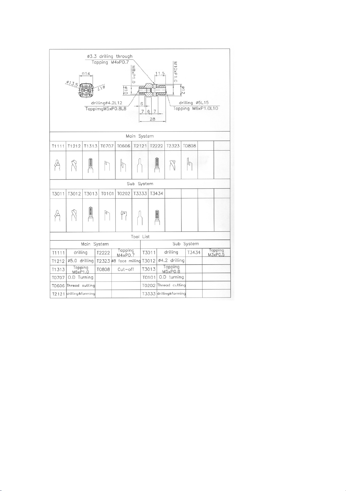
EXAMPLE PROGRAM 1
3-39
Page 69

3-40
Example Program 1:(1/4)
O0001;(Main System Program) X17.0;
M05
;
X18.1 Z15.5;
M11
;
G00 Z0.;
G04 X1.0
;
X13.0;
G300 X-2.0 Z31.0 T0808;
(Stop bar)
G01 X5.0 F0.08;
G50 Z0.; Z-0.02;
M10
;
G00 X7.5;
G04 X1.0; G01 X9.9 Z1.8 F0.08;
G00 X20.0 Z-1.0
;
Z6.0;
N1;(Center drilling) X8.5 Z7.0 F0.04;
G97 M13 S2500 T1111
;
Z8.0 F0.08;
G99 G00 X0. Z-1.0
;
X12.0 ,R0.6;
M1000
;
Z15.0;
G01 Z3.0 F0.08
;
X18.0;
G00 Z-1.0
;
G00 X20.0;
M1001
;
N5;(O.D. Thread cutting)
N2;(ψ5.0 Drilling) G97 M13 S1500 T0606;
G97 M13 S2500 T1212
;
G99 G00 X18.0 Z-2.0;
G99 G00 X0. Z-1.0
;
M35;
M1002; G92 X9.5 Z7.0 F1.0;
G01 Z15.0 F0.08
;
X9.2;
G00 Z-3.0; X9.0;
M1003; X8.8;
N3;(Rigid Tapping M6X1.0) X8.7;
G97 M13 S1000 T1313; G00 X20.0 M05;
G99 G00 X0. Z-3.0
;
N6;(Side drill ψ3.3 Form turning)
M1004
;
M38;
M29
;
T2121;
G84 Z12. F1.0
;
M113 S2500;
G80
;
G98 G00 Z11.5 C0.;
G00 Z-3.0
;
X14.0;
M1005
;
G01 X0. F100;
N4;(O.D. Turning) G00 X14.0;
G97 M13 S3000 T0707
;
C180.;
G99 G00 X19.0 Z-0.5
;
G01 X0. F100;
G01 X12.5 F0.1
;
G00 X20.0;
Z14.9 F0.08
;
M115;
Page 70

3-41
Example Program 1: (2/4)
M39; M25;
N7;(Side Tapping M4X0.7) M1007;
M38; G01 X-2.0 F0.04;
T2222
;
M1008;
M113 S1000
;
M1009;
G99 G00 Z11.5 C0.
;
M135;
X15.0
;
M09;
G188 X0. F0.7
;
M95;
G00 C180.
;
G04 X0.02;
G188 X0. F0.7
;
/M92;
G00 X20.
;
M96;
M115; M01;
M39
;
M1010;
N8;(Side ψ8.0 Milling) M30;
M38;
T2323;
M113 S1000;
G98 G00 Z18.0 C0.;
Y13.0;
X14.0;
G01 Y-13.0 F150;
G00 C90.;
G01 Y13.0 F150;
G00 C180.;
G01 Y-13.0 F150;
G00 C270.;
G01 Y13.0 F150;
G00 X20.0;
M115;
M39;
N9;(Cut-off)
T0808;
M133 S2000;
G99 G00 X20.0 Z30.0;
M1006;
M24;
G04 X3.0;
Page 71

3-42
Example Program 1:(3/4)
O0001;(Sub System Program) G01 X7.9 Z-1.2 F0.08;
N1;(Center drilling with main system
simultaneously)
Z-6.0;
M05; X10.0 ,C0.4;
G28 W0.
;
Z-7.0;
T3011
;
X18.0;
G99 G00 X0.; G00 Z50.0;
M1000
;
N5;(Thread cutting)
G97 M13 S2500; G97 M13 S1500 T0202;
G00 X0. Z1.0
;
G99 G00 X15.0 Z5.0;
G01 Z-3.0 F0.08
;
M35;
G00 Z10.0
;
G92 X7.5 Z-5.5 F1.0;
M1001
;
X7.2;
N2;(ψ4.2 drilling with main system
simultaneously)
X7.0;
G97 M13 S2500 T3012; X6.8;
M1002; X6.7;
G99 G00 X0. Z1.0
;
G00 Z30. M05;
G01 Z-10.0 F0.06; N6;(Side drill ψ2.5 Form turning)
G00 Z10.0
;
M38;
M1003
;
T3333;
N3;(Tapping M5X0.8 drilling with
main system simultaneously)
M113 S2500;
G97 M13 S1000 T3013
;
G98 G00 X13.5 C45.;
M1004
;
Z-6.0;
G99 G00 X0. Z5.0; G01 Z-12.0 F80;
M29
;
G00 Z-6.0;
G84 Z-8.0 F0.8; C135.;
G80
;
G01 Z-12.0 F80;
G00 Z5.0
;
G00 Z-6.0;
M1005
;
C225.;
N4;(O.D. Cutting) G01 Z-12.0 F80;
G97 M13 S2500 T0101
;
G00 Z-6.0;
G99 G00 X10.5
;
C315.;
Z1.0
;
G01 Z-12.0 F80;
G01 Z-6.9 F0.08
;
G00 Z30.;
G00 X12. Z0.
;
M115;
G01 X5.0 F0.08
;
M39;
Z0.02; N7;(End face Tapping M3X0.5)
G00 X6.5; M38;
Page 72

3-43
Example Program 1:(4/4)
T3434
;
G28 W0.;
M113 S1000
;
M1010;
G99 G00 X13.5 C45.
;
M30;
Z-3.0;
G284 Z-11.0 F0.5;
G00 C135.;
G284 Z-11.0 F0.5;
G00 C225.;
G284 Z-11.0 F0.5;
G00 C315.;
G284 Z-11.0 F0.5;
G00 Z30. M09;
M115;
M39;
N8;(Ejecting parts)
T3535;
G00 X0.;
Z0.;
M11;
G04 X2.0;
M33;
G28 W0.;
N9;(Sub spindle catch work piece)
T3030;
G00 X0.;
M11;
M1006;
G00 Z0.;
M24;
G98 G01 Z-14.0 F200;
M25;
M10;
G4 X1.0;
M1007;
M1008;
G98 G01 W1.0 F200;
M1009;
Page 73
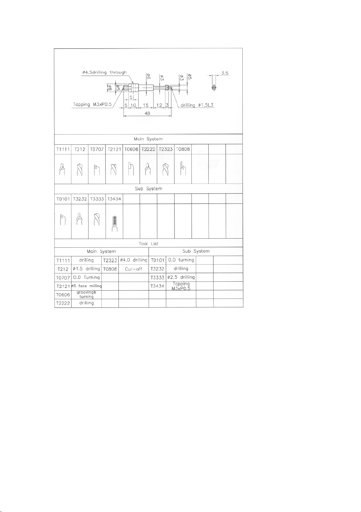
EXAMPLE PROGRAM 2
3-44
Page 74

3-45
Example Program 2:(1/3)
O0002;(Main system program) T2121;
M05
;
M113 S2000;
M11
;
G98 G00 Z4.5 C0.;
G04 X1.0
;
G00 Y5.0;
G300 X-2.0 Z51.0 T0808
;
X3.5;
G50 Z0.
;
G01 Y-5.0 F150;
M10
;
G00 C180.;
G04 X1.0
;
G01 Y5.0 F150;
G00 X12.0 Z-1.0
;
G00 X20.0;
M1000
;
M115;
N1;(Center drilling) M39;
G97 M13 S3000 T1111
;
N5;(O.D. Gouge turning 2mm)
G99 G00 X0. Z-1.0; G97 M13 S3000 T0606;
G01 Z1.0 F0.06; G99 G00 X9.0 Z7.5;
G00 Z-1.0
;
G01 X5.05 F0.08;
N2;(ψ1.5 Drilling) Z8.0 ,C0.3 F0.06;
G97 M13 S3000 T1212; X3.0;
G99 G00 X0. Z-1.0
;
Z18.0;
G01 Z4.0 F0.06; X6.0 ,C0.3;
G00 Z-1.0
;
Z33.0;
N3;(O.D. Turning) X7.4;
G97 M13 S3500 T0707
;
X8.1 Z33.3;
G99 G00 X9.0 Z-1.0
;
G00 X12.0 M05;
G01 X4.0 F0.1
;
N6;(Side drilling)
Z2.9 F0.06
;
M38;
G00 X5.0 Z0.
;
T2222;
G01 X1.0 F0.06
;
G98 G00 Z38.0 C90.;
Z-0.02
;
X10.0;
X3.0 ,C0.3
;
G01 X4.5 F100;
Z3.0; G00 X10.0;
X5.0 ,C0.3
;
C270.;
Z17.9; G01 X4.5 F100;
X7.0; G00 X20.;
X8.1 Z18.5
;
M115;
G0 X12.0 M05; M39;
N4;(ψ5 Side face milling) N7;(ψ4.5 Side drilling)
M38
;
M38;
Page 75

3-46
Example Program 2:(2/3)
T2323;
M113 S2500;
G98 G00 Z38.0 C90.;
X10.0;
G01 X-10.0 F100;
G00 X20.0;
M115;
M39;
N8;(Cut-off)
T0808;
M133 S2000;
G99 G00 X9.0 Z50.0;
M1001;
M24;
G04 X3.0;
M25;
M1002;
G01 X-2.0 F0.04;
M1003;
M1004;
M135;
M09;
M95;
G04 X0.02;
/M92;
M96;
M01;
M1005;
M30;
Page 76

3-47
Example Program 2:(3/3)
O0002;(Sub system) G00 X0.;
N1;(O.D. Turning) Z0.;
M05
;
M11;
G28 W0.; G04 X2.0;
T0101
;
M33;
M1000
;
G28 W0.;
G97 M13 S2500
;
N6;(Sub spindle catch part)
G99 G00 X9.0
;
T3030;
Z0.
;
G00 X0.;
G01 X-0.5 F0.08
;
M11;
Z0.02
;
M1001;
X5.0 ,C0.4
;
G00 Z0.;
Z-5.0; M24;
X7.4
;
G98 G01 Z-32.0 F200;
X8.1 Z-5.3; M25;
G00 X10.0 Z50.0; M10;
N2;(Center drilling) G04 X1.0;
G97 M13 S2500 T3232; M1002;
G99 G00 X0. Z1.0
;
M1003;
G01 Z-1.5 F0.08
;
G98 G01 W1.0 F200;
G00 Z10.0
;
M1004;
N3;(ψ2.5 Drilling) G28 W0.;
G97 M13 S2500 T3333
;
M1005;
G99 G00 X0. Z1.0
;
M30;
G01 Z-11.0 F0.06;
G00 Z10.0;
N4;(M3X0.5 Tapping)
G97 M13 S1000 T3434;
G99 G00 X0. Z5.0;
M29;
G84 Z-11.0 F0.5 ;
G80;
G00 Z30.0;
M05;
M09;
N5;(Ejecting part)
T3535;
Page 77
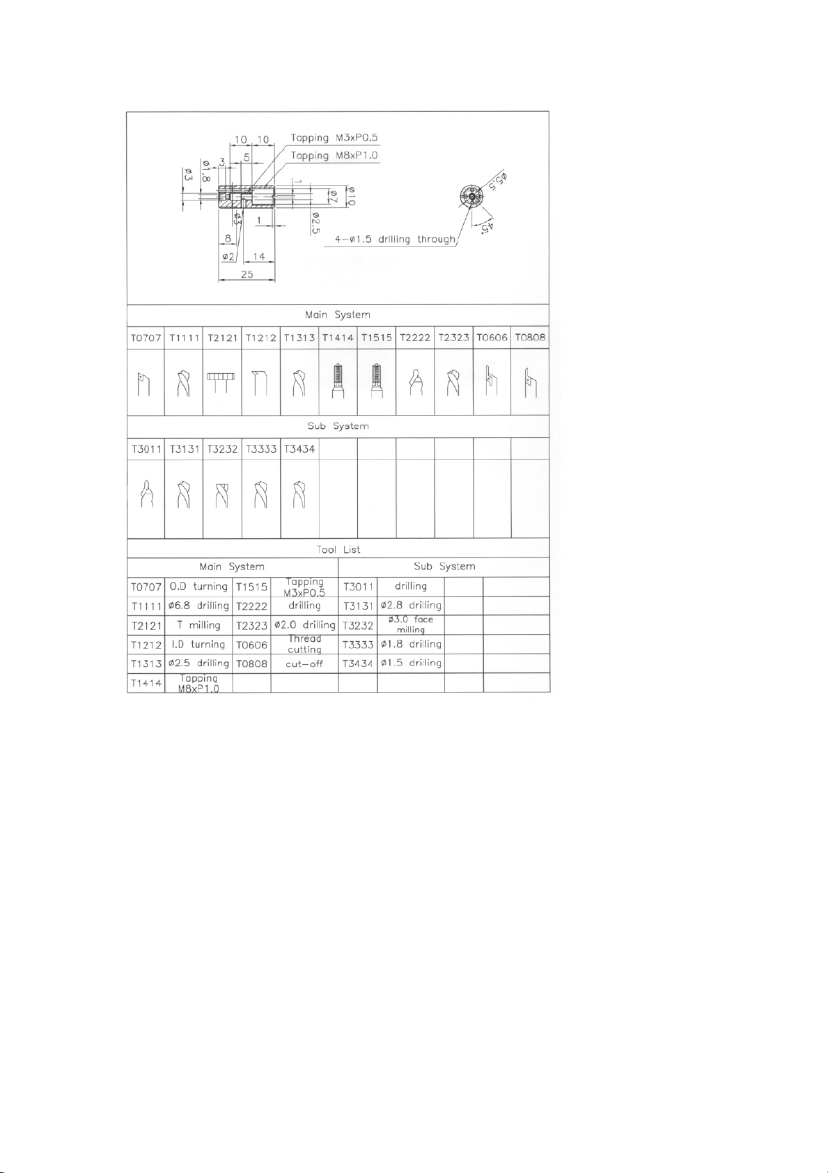
EXAMPLE PROGRAM 3
3-48
Page 78

3-49
Example Program 3:(1/4)
O0003;(Main System Program) G99 G00 X0. Z-1.0;
M05
;
G50 U6.0;
M11; G00 X8.6;
G04 X1.0
;
G01 Z0.03 F0.06;
G300 X-2.0 Z28.0 T0808
;
X7.0 Z1.0;
G50 Z0.; Z10.0;
M10
;
X6.5;
G04 X1.0; G00 Z-1.0;
G00 X15.0 Z-1.0
;
G50 U-6.0;
N1;(Turning End Face) N5;(ψ2.5 Drilling)
G97 M13 S3000 T0707
;
G97 M13 S3000 T1313;
G99 G00 X12.0 Z0.3
;
G99 G00 X0. Z-1.0;
G01 X10.1 F0.08;
G00 Z9.0
X9.4 Z0.
;
G83 Z21. Q4000 F0.06;
X7.0
;
G80;
Z-0.5
;
G00 Z-3.0;
G00 X15.0
;
N6;(M8X1.0 Tapping)
N2;(ψ6.8 Drilling) G97 M13 S1000 T1414;
G97 M13 S2500 T1111
;
G99 G00 X0. Z-3.0;
G99 G00 X0. Z-1.0; M29;
M1000
;
G84 Z9.8 F1.0;
G01 Z11.5 F0.08; G80;
G00 Z-1.0; G00 Z-3.0;
M05
;
N7;(M3X0.5 Tapping)
N3;(T type face milling) G97 M13 S1000 T1515;
M38
;
G99 G00 X0. Z-1.0;
T2121
;
G00 Z7.0;
M113 S2500
;
M29;
G98 G00 Z-4.0 C0.
;
G84 Z16.0 F0.5;
G00 Y10.0
;
G80;
X-1.0
;
G00 Z-1.0 M05;
G01 Y-10.0 F150
;
N8;(Side drilling)
G00 X20.0 Z-9.
;
M38;
M115
;
T2222;
M39
;
M113 S2500;
N4;(I.D. Turning) G98 G00 Z14.0 C225.;
G97 M13 S2500 T1212
;
X12.0;
Page 79

3-50
Example Program 3:(2/4)
G01 X7.5 F100
;
G99 G00 X12.0 Z27.0;
G00 X20.0
;
G01 X8.5 F0.06;
M115
;
X10.5 F0.15;
M39
;
W-1.4;
N9;(ψ2.0 Side drilling) X10.1;
M38
;
X8.5 W1.4 F0.04;
T2323
;
X10.0 F0.15;
M113 S2500
;
M1001;
G98 G00 Z14.0 C225.
;
M24;
X12.0
;
G04 X3.0;
G01 X-1.0 F100; M25;
G00 X20.0
;
M1002;
M115; G01 X-2.0 F0.04;
M39; M1003;
N10;(Thread cutting) M1004;
G97 M13 S1500 T0606; M135;
G99 G00 X15.0 Z17.0
;
M09;
M35
;
M95;
G32 X9.5 F1.0; G04 X0.02;
Z26.5
;
/M92;
X14.6
;
M96;
G00 Z17.0
;
M1005;
G32 X9.1 F1.0
;
M01;
Z26.5
;
M30;
X14.3;
G00 Z17.0;
G32 X8.8 F1.0;
Z26.5;
X14.2;
G00 Z17.0;
G32 X8.7 F1.0;
Z26.5;
X15.0;
G00 Z17.0;
N11;(Cut-off)
T0808;
M133 S2000;
Page 80

3-51
Example Program 3:(3/4)
O0003;(Sub System Program) G01 Z-3.0 F0.08;
N1;(Center drilling with Main system
simultaneously)
G00 Z10.0;
M05; N4;(ψ1.8 Drilling)
G28 W0.
;
G97 M13 S2500 T3333;
T3011
;
G99 G00 X0.;
G99 G00 X0.; Z-2.0;
M1000
;
G01 Z-6.0 F0.06;
G97 M13 S2500; G00 Z10.0 M05;
G00 Z1.0
;
N5;(ψ1.5 Drilling)
G01 Z-1.5 F0.08
;
M38;
G00 Z20.0 M05
;
T3434;
N2;(ψ2.8 Center & Eccentric drilling) M113 S3000;
M38
;
G98 G00 X5.5 C0.;
T3131
;
Z1.0;
M113 S2500
;
G83 Z-16.0 Q3000 F80;
G98 G00 X0. C0.
;
G00 Z1.0;
Z1.0
;
C90.;
G01 Z-3.8 F100
;
G83 Z-16.0 Q3000 F80;
G00 Z1.0
;
G00 Z1.0;
X5.5; C180.;
G01 Z-0.7 F100
;
G83 Z-16.0 Q3000 F80;
G00 Z1.0; G00 Z1.0;
C90.; C270.;
G01 Z-0.7 F100
;
G83 Z-16.0 Q3000 F80;
G00 Z1.0; G00 Z30.0;
C180.
;
M115;
G01 Z-0.7 F100
;
M39;
G00 Z1.0
;
N6;(Ejecting part)
C270.
;
T3535;
G01 Z-0.7 F100
;
G00 X0.;
G00 Z10.0
;
Z0.;
M115
;
M11;
M39
;
G04 X2.0;
N3;(ψ3.0 Face milling) M33;
G97 M13 S2500 T3232
;
G28 W0.;
G99 G00 X0.
;
N7;(Sub spindle catch part)
Z1.0
;
T3030;
Page 81

3-52
Example Program 3:(4/4)
G00 X0.;
M11;
M1001;
G00 Z0.;
M24;
G98 G01 Z-15.0 F200;
M25;
M10;
G04 X1.0;
M1002;
M1003;
G98 G01 W1.0 F200;
M1004;
G28 W0.;
M1005;
M30;
Page 82

3-53
3.12 CUTTING TOOL INSTALLATION AND OPERATION
MAIN SYSTEM O.D. TOOLINSTALLATION
There are eight positions for the O.D cutting tool in main system.(Tool No. 01~08).
Please be advised to use □12 shank only for Swiss type lathe. Please call the specific
tool No. and move the position to the surface of the bar. Screw the tool tight. For
example, if the diameter of the bar is 18mm and fixed on the No.7 position the steps
are as follows:
1. Switch MODE SELECTION KNOB to MDI MODE. Switch to the main system.
2. Press “PROG” button, and insert T0707; G0 X18.0 on the screen.
3. Press CYCLE START, and the machine will move to the No.8 position. Then move
to X 18.0 position.
4. Place the tool on the tool carriage, and move the tool knob until it touches the
surface of the bar. Screw the wedge block, but not too tight.
5. Switch to MPG MODE and X axis. Move the axis to the positive direction by using
the hand wheel. Screw the wedge block tight.
6. Finish. It is not necessary to set the tool length offset value.
Note: Cut-off tool must be fixed on No.8 position.
SUB SYSTEM SIDE DRILLING INSTALLATION
There are four positions for the side drill tool (Tool No.21~24) and it can be extended
to seven positions. Maximum shank diameter is 10mm. Please call the specific tool
No. and move the position to the surface of the bar. Screw the tool by ER 16 wrench.
Because the mirror function will be active with the side drill function, it is important to
set the coordinates of the X-axis to the positive direction when side drilling.
For example, if the diameter of the bar is 15mm, and fixed on the No.21 position the
steps are as follows:
1. Switch to MDI MODE and main system.
2. Press the “PROG” button, and insert T2121; G0 X15.0 on the screen.
3. Press CYCLE START, and the machine will move to the No.21 position. Then
move to X 15.0 position.
4. Place ER-16 tool holder with nut on the side drill device and screw the tool tight.
5. Move the tool nose to touch the surface of bar. Press EMERGENCY STOP, and
use ER-16 wrench and 19mm open-end wrench to screw the tool tight.
6. Release EMERGENCY STOP. Switch to HOME MODE and X-axis. Press positive
direction to move the tool away.
7. Finish. It is not necessary to set the tool length offset value.
Page 83

3-54
MAIN SYSTEM FACE DRILLING DEVICE INSTALLATION
There are five positions for the end face dill (tool no. 11~15). The maximum diameter
is 25mm.Normally fixed by ER-16 tool holder. Place proper tool length to fix on the
tool holder. According to the cut-off surface, call the specific tool No. and move to the
center point of the bar. Then screw the tool tight. For example, if we want to fix tool on
no.12 position, the steps are as follows:
1. Move the bar (Z -is) to the proper cut-off position, and turn the end face with the
cut-off tool. Then move the cut-off tool away.
2. Switch to MDI mode and main system.
3. Press the “PROG” button and insert T1212; G0 X0. on the screen
4. Press CYCLE START, and the machine will move to the No.12 position (Y-axis).
Then move the X-axis to the center of the bar.
5. According to the cut-off surface of the bar, place the tool holder with the tool to the
No.12 position. Move the tool nose until it touches the cut-off surface. Screw it
tight.
6. Finish. It is not necessary to set the tool length offset value.
TOOL OPERATION OF SUB SYSTEM
There are four positions for sub system end face drilling. The device is designed to be
interchangeable, which means it can be changed to fix the tool holder or rotating tool
holder and the most inside can be installed a outer diameter tool carrier (option
function). The tool number can be set in the geometry compensation menu but six tool
numbers have been preset by the manufacturer (T30~T35). While calling the tool
number, the X-axis will move to a specific position. Please see the following
instructions:
1. T30□□:When calling T30□□,the X-axis will move the sub spindle to the
center of the main spindle. Normally it is used to catch the working piece from the
main spindle to sub spindle. Or use the same drilling tool system as the main
system.
2. T31□□: When calling T31□□, the X-axis will move the sub spindle to the first
tool of the end face drilling device.
3. T32□□: When calling T32□□, the X- axis will move the sub spindle to the
second tool of the end face drilling device
4. T33□□: When calling T33□□,the X- axis will move the sub spindle to the third
tool of the end face drilling device
5. T34□□: When calling T34□□, the X- axis will move the sub spindle to the
fourth tool of end face drilling device
6. T35□□: When calling T35□□, the X- axis will move the sub spindle to the
ejecting position of the working part.
NOTE: The zero point position of the working part should be set in the geometry
compensation menu.
Page 84

3-55
SUB SYSTEM TOOL INSTALLATION
Before placing the tool on the tool carriage, please confirm tool type and position and
fix with proper components. For example, if we want to install O.D. tool on no.31
position, please measure the plane of fixing O.D. tool in parallel with the X-axis.
1. O.D. tool carriage: The O.D. tool carriage only installs on the No.31 position. Use
the □12mm shank for O.D. tool. After finishing the installation, please choose the
tool number and set the geometry compensation value.
2. Fixed tool holder: It can fix the drilling tool or I.D. tool. Use the proper ER-16 tool
holder to fix the tool and screw tight with the ER-16 wrench. After finishing
installation, please choose the tool number and set the geometry compensation
value.
3. Rotating tool holder: It can fix the drilling and milling tool. Press EMERGENCY
STOP before installing it. Use the proper ER-16 tool holder to fix the tool and
screw tight with the ER-16 and 19mm open end wrench. After finishing installation,
release EMERGENCY STOP and choose the tool number and set the geometry
compensation value.
NOTE: It’s better to use the same length of drilling tools to avoid tool interference.
Page 85
3-56
3.13 EDIT & EXECUTE NC PROGRAM
CREATE A NEW PROGRAM
1. Switch [SYSTEM SELECTION KNOB] to specific system.
2. Switch [MODE SELECTION KNOB] to EDIT mode.
3. Press [PROG] button to display the file list, and then press [OPRT].
4. Insert new program name, and press [CREATE PROGRAM] to create a new program.
It will add a new program name on the screen.
5. Move the yellow cursor to new program.
6. Press [MAIN PROGRAM]. A [@] mark will appear at the left side of the specific
program name, then press [INPUT] to start editing this NC program.
7. The screen is shown as following.
DEVICE:CNC_MEM (CURRENT FOLDER:/USER/PATH1/)
RETURN TO UPPER FOLDER
〈
FOLDER〉
O0001
1KBYTE 2006/10/03 12:57:22
O0002
1KBYTE 2006/10/05 15:50:32
@ O0003
2KBYTE 2006/10/10 08:58:25
O0005
2KBYTE 2006/10/20 16:37:52
O0010
1KBYTE 2006/11/03 10:28:33
O0020
1KBYTE 2006/11/13 12:46:10
O0025 3KBYTE 2006/11/23 12:11:58
O0030
1KBYTE 2006/11/30 12:20:06
A〉
EDIT **** 15:20:58 PATH1
PROGR
AM
FOLDE
R
NEXT CHECK (OPRT)
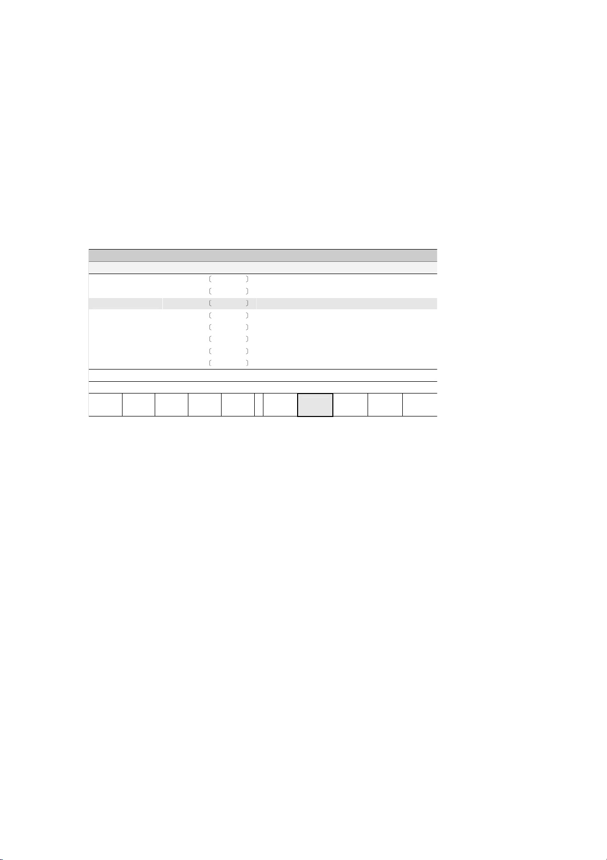
Figure 1
Page 86
3-57
DEVICE:CNC_MEM (CURRENT FOLDER:/USER/PATH1/)
RETURN TO UPPER FOLDER
〈
FOLDER〉
O0001
1KBYTE 2006/10/03 12:57:22
O0002
1KBYTE 2006/10/05 15:50:32
@ O0003
2KBYTE 2006/10/10 08:58:25
O0005
2KBYTE 2006/10/20 16:37:52
O0010
1KBYTE 2006/11/03 10:28:33
O0020
1KBYTE 2006/11/13 12:46:10
O0025
3KBYTE 2006/11/23 12:11:58
O0030 1KBYTE 2006/11/30 12:20:06
A〉O0168
EDIT **** 15:21:16 PATH1
DEVICE
CHANG
E
PROGR
AM
SEARC
H
MAIN
PROGR
AM
DETAIL
ON
CREATE
PROGR
AM
CREATE
FOLDERDELETE
RENAM
E
PROGR
AM
CANDE
NS
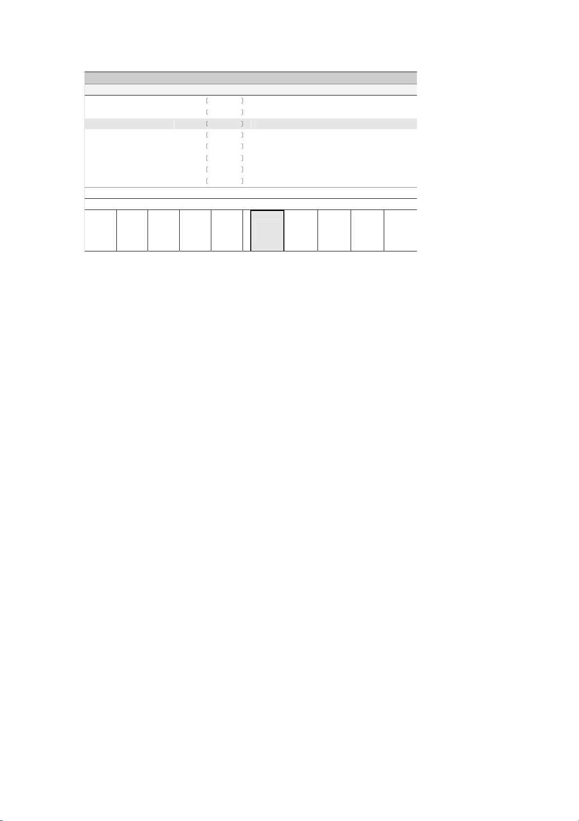
Figure 2
Page 87
3-58
CALL NC PROGRAM
1. Switch [SYSTEM SELECTION KNOB] to specific system.
2. Switch [MODE SELECTION KNOB] to EDIT mode.
3. Press [PROG] button to display the file list, then press [OPRT]。
4. Move the yellow cursor to new program.
5. Press [MAIN PROGRAM]. A [@] mark will appear at the left side of the specific
program name, then press [INPUT] to load this NC program.
6. Please check Figure 3.
DEVICE:CNC_MEM (CURRENT FOLDER:/USER/PATH1/)
RETURN TO UPPER FOLDER
〈
FOLDER〉
O0002
1KBYTE 2006/10/05 15:50:32
O0003
2KBYTE 2006/10/10 08:58:25
O0005
2KBYTE 2006/10/20 16:37:52
O0010
1KBYTE 2006/11/03 10:28:33
O0020
1KBYTE 2006/11/13 12:46:10
O0025
3KBYTE 2006/11/23 12:11:58
O0030
1KBYTE 2006/11/30 12:20:06
@ O0168
1KBYTE 2006/12/01 15:21:16
A〉
EDIT **** 15:21:20 PATH1
DEVIC
E
CHAN
GE
PROG
RAM
SEAR
CH
MAIN
PROG
RAM
DETAI
L ON
CREAT
E
PROG
RAM
CREAT
E
FOLDE
R
DELETERENA
ME
PROG
RAM
CANDE
NS
Figure 3
Page 88
3-59
EXECUTE NC PROGRAM:
1. Switch [MODE SELECTION KNOB] to EDIT mode, and press [PROG] to load main
and sub system NC program.
2. Switch [MODE SELECTIION KNOB] to AUTO mode, and switch [SYSTEM
SELECTION KNOB] to auto.
3. Press [CHECK] to see both NC programs on the screen (Figure 4).
4. Make sure both programs start at the first block of each program, both axes stay in
safety area, and that the bar feeder is ready.
5. Press cycle start to run NC program.
PATH1 O0168 N00000 PATH2 O0168 N00000
O0168; O0168;
M05;
M11;
G300 X-2.0 Z50.0 T0808;
M05;
G28 W0.;
T3131;
ABSOLUTE
X1 13.780
Z1 58.351
Y1 110.352
C1 0.000
A1 256.210
DISTANCE TO GO
X1 0.000
Z1 0.000
Y1 0.000
C1 0.000
A1 0.000
ABSOLUTE
X1 55.380
Z1 66.351
C1 180.000
A1 335.789
DISTANCE TO GO
X1 0.000
Z1 0.000
C1 0.000
A1 0.000
G00 G40 G54 F M
G97 G25 G64 H
G69 G22 G18 T
G21 G67 G80 S
G00 G40 G54 F M
G97 G25 G64 H
G69 G22 G18 T
G21 G67 G80 S
MEM **** *** *** 16:38:39 PATH1
PROG
RAM
FOLDE
R
NEXT
CHEC
K
(OPRT)
Figure 4
Page 89

3-60
3.14 G188/G284/G300 INSTRUCTION
G188 : Main system X axis side rigid tapping
G188 X____ F_____ ;
X: End point of rigid tapping
F: Pitch
Example:
M6XP1.0
M38;
T2121;
M113 S600;
G00 Z10.0 C0.;
X20.0 ;
G188 X0. F1.0 ;
G00 C90.0;
G188 X0. F1.0;
G00 X25.0;
M115;
M39;
M30;
Page 90

3-61
G284 : Sub system Z axis face rigid tapping
G284 Z___ F___;
Z: End point of rigid tapping
F: Pitch
Example:
M5XP0.8
M38;
T3232;
M113 S1000;
G00 X7.0 C0. ;
Z5.0;
G284 Z-10.0 F0.8;
G00 C180. ;
G284 Z-10.0 F0.8;
G00 Z25.0;
M115;
M39;
M30;
Page 91

3-62
G300 : PROGRAM ZERO POINT RETURN
It is used to return program zero point while main system is starting running. Refer to G50
to set Z axis zero point.
G300 X_____ Z______ T0808 ;
X: The end coordinate of X axis while cut-off work piece
Z: Length of work piece + thickness of cu-off tool insert
NOTE: This function only for No.8 tool
Example:
M05; Spindle stop
M11; Chuck open
G04 X1.0; Pause one second
G300 X-2.0 Z80.0 0. T0808; Z axis return program start point.
G50 Z0. ; Set present coordinate as Z axis zero point
M10; Chuck close
G04 X1.0 Pause one second.
G00 X21.0 Z-1.0 ; move tool away from spindle.
G300 step: 1. Move tool axis (Y axis)
2. Move X axis
3. Move Z axis
Page 92

3-63
3.15 WORK PIECE COUNT FUNCTION
Work piece count function is use for counting present finished work piece, or stop
machining while finished work piece reach the setting value.
When execute M30 one time, the counter will add one itself.
Searching function screen:
1. Press OFS/SET bottom to SETTING (TIMER). Press OFS/SET again, if not show the
menu on the screen.
2. The menu shown below.
SETTING(TIMER)
PART TOTAL 5687
PART REQUIRED 2000
PART COUNT 1568
PWER ON 578H 3M
RUN TIME 238H 8M 58S
CUTTING TIME 156H 26M35S
FREE PURPOSE 0H 0M 0S
CYCLE TIME 0H 0M 0S
DATE 2006/10/30
TIME 15:58:36
A>
Function instruction
PART TOTAL: present finished parts
PART REQUIRED: Maximum working parts. SET 0 to disable this function.
PART COUNT: Stop machine while reach PART TOTAL value.
Switch to MDI to change parameters value. Move yellow cursor to specific position and
insert value then press INPUT to modify the value.
Page 93

4 MACHINE MAINTENANCE AND ALARM MESSAGE
4.1 TOOL OFFSET FUNCTION
The tool offset function is to compensate the difference between the ideal tool
condition and practical tool condition. It includes tool geometry, tool wear, and
tool nose radius compensation.
1. T code for tool offset
Number of tool offset compensation is shown as following
T
□□ □□
NO. OF WEAR AND GEOMETRY
NO. OF TOOL
For example: 1. Assume tool No.8 and compensation No.8, T code = T0808.
2. Assume tool No.12 and compensation No 15, T code = T1215
4-1
Page 94

4.2 TOOL GEOMETRY COMPENSATION
Tool geometry compensation is to compensate tool location. Normally, it is not
necessary for the main system, only for the sub system. It is shown as
following.
1. After installing the tool, move to the specific location.
2. Press [OFS/SET]→compensate→geometry. It will display the tool offset
information.
3. Move the cursor to the specific tool and axis.
4. Input axis name and offset value, and press [ ] to save the values.
NO. X AXIS Z AXIS RADIUS T
G001 0.000 0.000 0.000 0
G002 0.000 0.000 0.000 0
G003 118.900 68.000 0.000 0
G004 0.000 0.000 0.000 0
G005 168.880 69.000 0.000 0
G006 0.000 0.000 0.000 0
G007 0.000 0.000 0.000 0
G008 0.000 0.000 0.000 0
G009 0.000 0.000 0.000 0
G010 0.000 0.000 0.000 0
G011 0.000 0.000 0.000 0
G012 0.000 0.000 0.000 0
G013 0.000 0.000 0.000 0
G014 0.000 0.000 0.000 0
G015 0.000 0.000 0.000 0
G016 0.000 0.000 0.000 0
G017 0.000 0.000 0.000 0
4-2
Page 95

4.3 TOOL WEAR COMPENSATION
Tool wear compensation is to compensate the tool dimension with tool nose
abrasion. It is shown as following.
1. Switch system knob switch to specific system.
2. Press [OFS/SET] →compensate → geometry, It will display the tool offset
information.
3. Move the cursor to specific tool and axis.
4. Input the value to the specific location and press [INPUT] or [+INPUT].
A. [INPUT]: replace srcinal value to present value.
B. [+INPUT]: srcinal plus present value.
NO. X AXIS Z AXIS RADIUS T
W001 0.000 0.000 0.000 0
W002 0.000 0.000 0.000 0
W003 0.000 0.100 0.000 0
W004 0.000 0.000 0.000 0
W005 0.060 0.000 0.000 0
W006 0.100 0.050 0.000 0
W007 0.150 0.000 0.000 0
W008 0.000 0.000 0.000 0
W009 0.000 0.000 0.000 0
W010 0.000 0.000 0.000 0
W011 0.000 0.000 0.000 0
W012 0.000 0.000 0.000 0
W013 0.000 0.000 0.000 0
W014 0.000 0.000 0.000 0
W015 0.000 0.000 0.000 0
W016 0.000 0.000 0.000 0
W017 0.000 0.000 0.000 0
4-3
Page 96
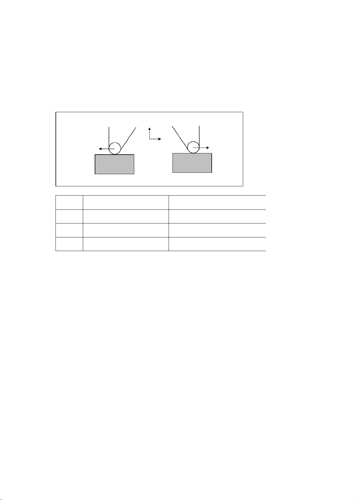
4.4 TOOL NOSE RADIUS COMPENSATION
If there is any error between the program position and the practical position, it
can be compensated by G40, G41, and G42. The so-called tool nose radius is
pretending a radius from the center of tool nose to the edge of tool nose. While
turning chamfer, ramp, and circular turning, it is necessary to use tool nose
radius compensation, and specify the cutting path and moving direction with
proper G codes.
G CODE PART LOCATION TOOLPATH
G40
Any direction(compensation
cancel)
Moving along program path
G41 Right side of moving direction Moving along left side of program path
G42 Left side of moving direction Moving along right side of program path
G42
G41
X
Z
Part
Part
4-4
Page 97
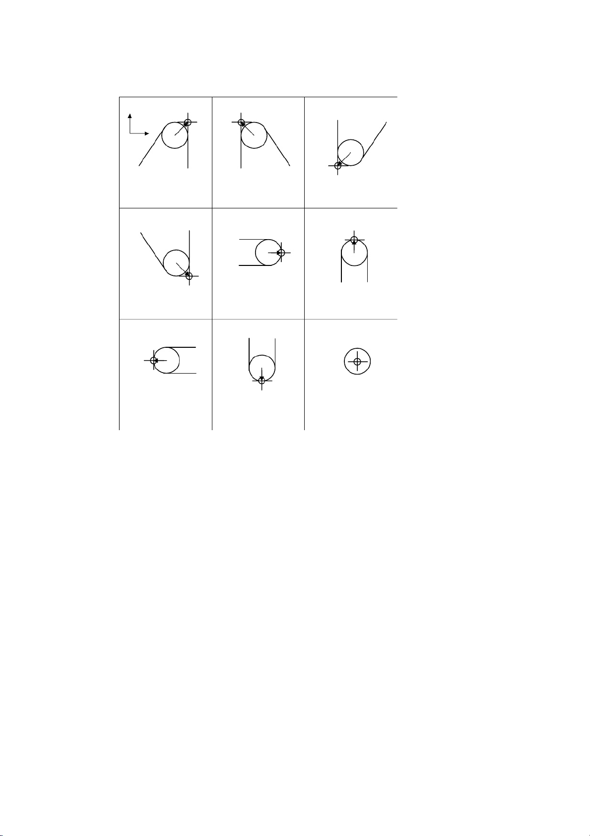
Before using tool nose radius compensation, the user has to set tool nose
radius and direction. There are 9 types, shown as follows.
1 2 3
Z
X
4 5 6
7 8 0 or 9
4-5
Page 98
4.5 Y AXIS TOOL OFFSET
While machining, it might happen that the center of the tool (Y-axis) differs with
the srcinal. It can be compensated by Y-axis tool offset. Please see the
following steps.
1. Press [OFS/SET] → [XX]→[XX]→[Y OFFSET] to enter Y-axis offset
menu.
2. Move the yellow cursor to the specific position.
3. Insert value and press INPUT or +INPUT to save the value.
NOTE: 1. [INPUT]: replaces srcinal value with present value.
2. [+INPUT]: srcinal plus present value.
Y AXIS TOOL OFFSET
NO. Y AXIS NO. Y AXIS
W001 0.000 W012 0.000
W002 0.000 W013 0.000
W003 0.000 W014 0.000
W004 0.000 W015 0.000
W005 0.000 W016 0.000
W006 0.000 W017 0.000
W007 0.000 W018 0.000
W008 0.150 W019 0.000
W009 0.000 W020 0.000
W010 0.000 W021 0.000
W011 0.000 W022 0.000
4-6
Page 99

4.6 ALARM MESSAGE & TROUBLESHOOTING
1000 AIR LOW PRESSURE
REASON: The air pressure unit signal X0.6 is 0.
SOLUTION: 1. Check air pressure
2. Check X 0.6 circuit.
1002 PARTS CHECK OK
REASON: Working piece has reached the setting value.
SOLUTION: Set new value and press RESET button to clear alarm message.
2000 LUBRICATION LOW LEVEL
REASON: Insufficient lubrication oil.
SOLUTION: 1. Refill lubrication oil.
2. Check X0.4 circuit.
2001 COOLANT MOTOR LOAD
REASON: Coolant motor overloaded and the breaker switched itself off.
SOLUTION: 1. Check motor current and circuit breaker.
2. Check X 0.1 circuit.
2002 BAR FEED ALARM
REASON: CNC system got alarm message from bar feeder.
SOLUTION: 1. Check bar feeder and repair the problems. Then press RESET
button to clear alarm message.
2. Check X 2.4 circuit.
2003 PARTS CATCHER UNINPOSITION
REASON: Parts catcher does not return to the right position.
SOLUTION: 1. Check the position of parts catcher
2. Check the light of the proximity sensor, and X1.2=1
2004 Z- AXIS LIMIT MODE ERROR
REASON: Z-axis limit has two modes at the same time.
SOLUTION: Switch PN signal (PLC signal) to either Z LIMIT 2 or Z LIMIT3.
4-7
Page 100

2006: CHUCK SENSOR ERROR
REASON: While the chuck of the main system is in OPEN/CLOSE, the
proximity sensors do not activate or activate at the same time.
SOLUTION: 1. Adjust the position of proximity sensors.
2. Check X1.0, X1.1 signal.
2007 SINDLE STOP PLEASE
REASON: Executed M11 or press chuck OPEN/CLOSE while spindle is
rotating.
SOLUTION: Press RESET button to clear alarm message. The spindle must
be stopped to open the chuck.
2009 SPINDLE LOCK RELEASE
REASON: Spindle is running while locked.
SOLUTION: 1. Release spindle before it rotates.
2. Check X1.7 signal.
2010 CHUCK CLOSE PLEASE
REASON: Executed NC program or ran spindle while chuck is open.
SOLUTION: Close the chuck before executing NC program or running spindle.
2013 Z+OT
REASON: Z+ direction over travel, and over the range of D1212 parameter.
SOLUTION: Hold Z- bottom and move Z-axis away from limit switch by using
MPG.
2016 DOOR CLOSE PLEASE
REASON: Ran NC program with door not closed.
SOLUTION: 1. Close door before running NC program.
2. Check X2.0 circuit.
2017 Z-OT
REASON: Z- direction over travel, and over the range of D1216 parameter.
SOLUTION: Hold Z+ bottom and move Z-axis away from limit switch by using
MPG
4-8
 Loading...