

Jinma JM300, JM354E Operator Manual
OPERATION MANUAL
Original Instruction
()
300E-354E
MADE IN CHINA

Preface
Contents
Chapter One Precautions for Safe Operations
Chapter Two General Description
-------------------------------------------------------------------------7
Chapter Three Some key Technical Specifications of the Tractors
3.1
Data of Whole Uni
3.2
Engine Parameter
3.3 Transmission System---------------------------------------------------------------------------------------10
3.4
Travel, Steering and Braking Systems
3.5
Working U nit
3.6
Ele ctr ical Sy stem
3.7
Liquid Filling Capacity
---------------------------------------------------------------------------------------------12
Chapter Four Operation of the Trac tor
4.1 The Fuel and Lubricating Oil of the Tractor ----------------------------------------------------------14
4.2 Water--------- --- --- ------- --- ---- --- --- ---- --- ------- --- --- ---- --- --- ---- --- ------- --- --- ---- --- --- ------- --1 4
4.3 Running-in --------------- ---- --- --- ---- --- --- ---- --- ------- --- --- ---- --- --- ------- --- ---- --- --- ---- --- --- --15
--------------------------------------------------------------------------------------8
-----------------------------------------------------------------------------------------9
------------------------------------------------------------11
----------------------------------------------------------------------------------------13
--------------------------------------------------------------------------------13
----------------------------------------------------------------14
-----------------------------------------------------1
---------------------------8
4.4
Steering Mechanism and Meters
4.5 Control and D riv e----- ---- --- --- ---- --- ------------- ---- --- --- ---- ------------- --- ---- --- --- ---- --- --------19
4.6
Operati on and Us e of th e Worki ng Units of Tra ct or
Chapter Five Technical Maintenance for the Tractor
5.1
Shift Technical Maintenance
5.2
I-grade Tec hnical Maint enance
5.3
II-grade Te chnical Maintenance
5.4
III-grade Technica l Maintenance
5.5
Technical Maintenance in Winter
5.6 Techincal M aintenan ce for Long-ter m Storag e--------- ------ ---------- ------- ------- ------ ------- ----29
--------------------------------------------------------------------17
-----------------------------------------22
-------------------------------------------27
-------------------------------------------------------------------------27
--------------------------------------------------------------------27
-------------------------------------------------------------------28
-----------------------------------------------------------------28
------------------------------------------------------------------29
1

Chapter Six Structure and Maintenance of the Tractor
s-------------------------------------31
6.1
Transm ission System
6.1.1 Clutc h--------- --- ------------- ---- --- --- ---- --- --- -------------- --- --- ---- --- --- ---- ----------------------31
6.1.2 Struct ur e an d Wor kin g P rin ci pa l of S ha ft C ou pl in g------ --- --- --- ---- --- ------------- ---- --- --- --3 4
6.1.3 Gear Box Assembly--------------------------------------------------------------------------------------35
6.1.4 Differ en tia l Ge ar a nd Dif fer en tia l L oc k----- ---- --- --- -------------- --- --- ---- ------------- --- ---- --3 6
6.1.5 Fina l Tr ans mission------------ --- ---- --- ------------- ---- --- --- ---- ------------- --- ---- --- --- ---- --------39
6.2
Travel& Steering System
6.2.1 Hydraulic Steering Control Unit (SCU)---------------------------------------------------------------40
6.2.2 Brake
6.2.3 Tw o -wheel Front Drivi n g A xle
6.2.4 Front Drivin g Axle--------------- -------------- --- --- ---- --- --- ---- ------------- --- ---- --- --- ---- --- -----47
6.2.5 Wheels------------ ------- ------ ------- ------- ------ ---------- ------- ------- ------ ------- ---------- ------- --51
6.3
Working U nit
6.3.1 Suspendin g S ys tem----- ---- --- --- -------------- --- --- ---- --- --- -------------- --- --- ---- --- ------------- 53
6.3.2 Structure and use of PTO Shaft------------------------------------------------------------------------58
6.4
Electric Installation
------------------------------------------------------------------------------------------------------43
---------------------------------------------------------------------------------------------53
-----------------------------------------------------------------------------------31
-----------------------------------------------------------------------------40
-----------------------------------------------------------------------45
-------------------------------------------------------------------------------------58
6.4.1 Engine----- ---- --- --- ----------------- ------------- ---- --- --- ---- --- ------------- ---- --- --- ---- --- --- ---- --5 8
6.4.2 Voltage Adju ste r--------- --- --- ---- --- --- ---- ------ ---- --- --- ---- --- --- ------- --- ---- --- --- ---- --- --- ---62
6.4.3 Battery----------------------------------------------------------------------------------------------------62
6.4.4 Starte r----- ---- --- --- ---- --- ------------- ---- --- --- ---- -------------------------- ---- --- --- ---- --- ---------64
6.4.5 Preh ea tin g P lu g--------- --- ------------- ---- --- --- ---- ------------- ----------------- --- --- ---- --- --------65
6.4.6 Fuse Box--------------------------------------------------------------------------------------------------65
6.4.7 Lig ht s a nd Si gn al D evi ce s--------- --- ------------- ---- --- --- ---- --- --- -------------- --- --- ---- --- --- --6 6
6.4.8 Gauges an d S w itc hes of E le ctr ica l E qu ip ment s--------------- ---- --- --- ---- --- ------------- ---- --- 67
6.5 Intake and Exhaus t S ys tem----- ---- --- ------------- ---- --- --- ---- --- --- -------------- --- --- ---- --- --- ---6 8
Chapt er Seven Main Tr oubles a nd The Solutions
7.1 Hard or Fail to Start the Diese l--------- ------------- --- ---- --- --- -------------- --- --- ---- ------------- --- 70
7.2 Self -stop of Di ese l----- ---- --- --------------------------- --- --- ---- --- --- ---- ------------- --- ---- --- --- ---7 0
7.3 Lack of Diesel Power------------------------------------------------------------------------------------71
-------------------------------------------------70
2

7.4 Abnorm al Exhau st Colo r----- ---- --- ------- --- --- ---- --- --- ---- --- ------- --- --- ---- --- --- ---- ------ ---- --7 1
7.5 Too High T empe rat ur e of Exh au st ed Wate r----- ---- --- --- -------------- ---------------- ---- --- --- ---- 72
7.6 Sudden Raise d S peed of Die se l (Fl ying D ie sel )----- ---- --- --- -------------- --- --- ---- --- --- ---------72
7.7 Abnormal Sound during Engine's Operating----------------------------------------------------------72
7.8 Too low pressure or Zero Pres su re of Diesel Oi l----- ---- --- --- -------------- --- --- ---- --- --- --------73
7.9 Brakes--------------- ---- --- --- ------- --- ---- --- --- ---- --- ------- --- --- ---- --- --- ------- --- ---- --- --- ---- --- -73
7.10 Clutch-----------------------------------------------------------------------------------------------------73
7.11 Hydraulic Suspending System--------------------------------------------------------------------------74
7.12 Electri c S ys tem----- ---- --- --- ---- --- ------------- ---- --- --- ---- --- --- -------------- --- --- ---- --- --- ---- --7 5
7.12.1 Starti ng Moto r----- ---- --- --- -------------- ---------------- ---- --- --- ---- --- --- ---- --------------------75
7.12.2 Bat ter y--------- --- --- -------------- ---------------- ---- --- --- ---- --- ----------------- ------------- --- ---- -7 6
7.12.3 Instrume nt s--------- ------------- --- ---- --- --- ---- ------------- --- ---- --- --- ---- --- ------------- ---- --- --7 6
7.12.4 Lights----- ---- --- --- ---- --- --- -------------- --- --- ---- --- --- ---- --- ------------- ---- --- --- ---- --- --- ---- -7 6
7.12.5 Si lic on Rect ifi cat io n G en er ator----- ---- --- --- ----------------- --------------------------------------77
Chapter Eight Appendix
Ele ctric Wir ing Map
8.1
8.2 Sizes of Suspending System
Spare Parts Along With the Machine
8.3
Tools Along With the Machine
8.4
-------------------------------------------------------------------------------------78
------------------------------------------------------------------------------------78
-----------------------------------------------------------------------------79
-------------------------------------------------------------80
--------------------------------------------------------------------81
3

Preface
Thank you for you r trust on our JINM A-35E and HHJM-35E seri es wheel tractors
(hereinafter JINMA-300E, HHJM-300E, JINMA-304E, HHJM-304E, JINMA-350E,
HHJM-350E and JINMA-354E, HHJM-354E). This series is reasonable in structure,
excelle nt in materia ls and complet ed in perfo rmance. I n order to help c ustomres operat e,
adjust , repair and maintain the products in a better way, and for better performance of
this series, we compile this operation manual. As for the operation & maintenance manue
of engines, please refer to diesel engine manual.
With tec hnical d evel opment a nd requi renment s from our cus tomers , descr iptions in
the manual may differ from the real structure of your tractors and the differences will be
involved in the next version. If what you want to know is beyond this book, plesease
contact the agent or the manufactuer.
“ ”
In this manual, this precaution symbol means some important safety information.
Seeing this symbol, you should read the contents below it carefully and inform other
operators to protect from possible hurts.
"
Warning
operations. Driver or stander-bys will be hurt or even die due to ignore.
"Important"
ignore can result in the damages to tractors or equipments.
Precaution Symbol
" and "
Attention
: These focus on correct steps or techniqus in operations. Your
": These focus on correct steps or techniqus in
Chapter One Precautions for Safe Operations
1.1 Only after reading the manual carefully, can the driver who has got special training and
driving licence with a full survey record operate the tractor. Tractor cannot be operated without
licenses.
1.2 This machine only can be operated, maintained and repaired by the perssons who are familiar
to its features and know the related safe operation rules.
1.3 Driver should pay especial attention to the precaution symbol on the machine.
1.4 It is forbid de n t o driv e tr a cto rs after being drun k, tired or takin g som e an tipsychotic.
1.5 1.5 During operating the tractor, driver should strictly complies with the informed steps
accrod ing to the presa ut ion sy mbo ls t o avo id acc ide nts. When t he symb ols ar e lo st, po lu ted or ab ra sed,
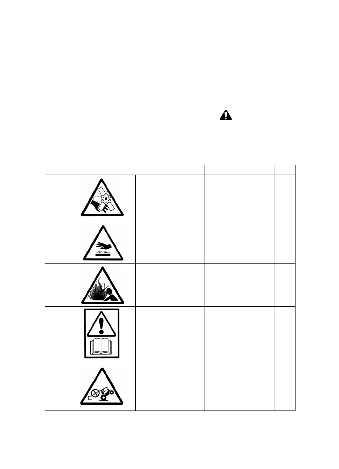
they should be replaced in time.( See Fig.1--1~Fig. 1-7 for precaution and operation symbols)
REF. MEANNING LOCATION Q.TY
1-1
:DANGER ENGINE
FAN
On the two sides of
radiator wind scooper
clearly.
2
1-2
1-3
1-4
1-5
:DANGER HOT
PARTS
DANGE R COOLING
SYSTEM UN DER
PRESSURE
CONSULT THE USER
MANUAL BEFORE
OPERATING THE
MACHINE
DO NOT US E CHAINS
OR ROPES JOINED
TO ROPS FOR
TOWING
:
1.On the two sides of
radiator wind scooper
clearly.
、2 Near to muffler.
On the position of fore
and lower part of
radiator.
On the PTO guard at the
back of the machine
On th e right insid e of
ROP.
2+1
1
1
1
1
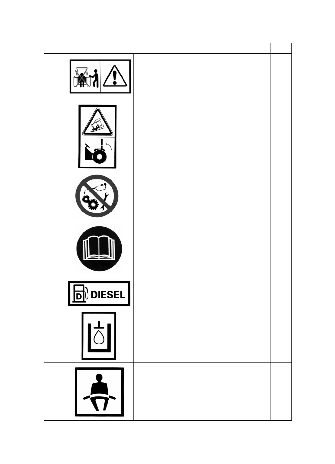
REF. MEANNING LOCATION Q.TY
DO NOT STAND
1-6
1-7
BETWEEN TRACTOR
AND EQUIPMENT
WHILE OPERATIING
HYDRAU LIC LIFT
ALWAYS LOCK ROPS
IN UPRIGHT
POSITION UNLESS IT
HAS TO BE FOLDED
DOWN TO ALLOW
OPERATION
UNDERNEATH
TREES OR BUSHES
At the central site of the
machine end.
On the left og the inside
of ROP
1
1
:PROHIBITION
1-8
1-9
1-10 DIESEL
1-11 HYDRAU LIC OIL On the oil tank 1
DO NOT LUBRICATE
MOVING PARTS
CONSULT THE
(MANUAL IF THE
MANUAL IS MISSING
,OR DAM A GED
CONTAC T THE
VEHICLE'S
On the two sides of
radiator wind scooper
clearly.
On th e right side o g
tractor instrument pa nel 1
)MANUFACTURER
On the front end of oil
tank
2
1
1-12 USE SAFET Y BELTS On th e right of the insid e
of ROP
2
1
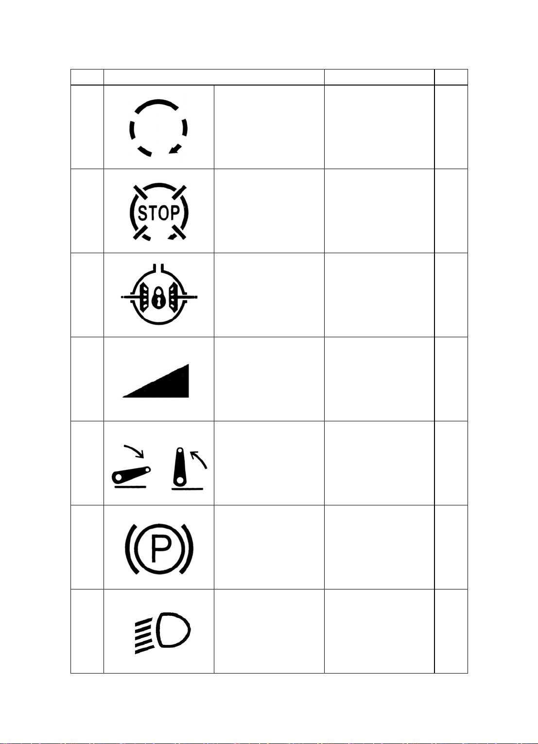
REF. MEANNING LOCATION Q.TY
1-13 STARTER CONTROL Abov e starting switch 1
1-14
1-15
1-16
1-17
ENGINE SHUT-OFF
CONTROL
DIFFERENTIAL LOCK
CONTROL
ENGINE ROTARY
VARIATIONS
THREE-OINTLIFTING
ECHAN ISM CONTROL
Above choke line 1
above ped al of
differential lock
On cover plate of hand
throttle assembly
At the starting and
ending positions of lifter
control lever
1
1
1
1-18
1-19
PARKING BRAKE
CONTROL
DIPPED-BEAM
HEADLAMPS
CONTROL
3
Near hand throttle
assembly
On the surface of head
lamps
1
1

REF. MEANNING LOCATION Q.TY
1-13 STARTER CONTROL Abov e starting switch 1
1-14
1-15
1-16
1-17
1-18
ENGINE SHUT-OFF
CONTROL
DIFFERENTIAL LOCK
CONTROL
ENGINE ROTARY
VARIATIONS
THREE-OINTLIFTING
ECHAN ISM CONTROL
PARKING BRAKE
CONTROL
Above choke line 1
above ped al of
differential lock
On cover plate of hand
throttle assembly
At the starting and
ending positions of lifter
control lever
Near hand throttle
assembly
1
1
1
1
1-19
DIPPED-BEAM
HEADLAMPS
CONTROL
4
On the surface of head
lamps
1

1.6 Befo re operation, a new tractor sho uld have a runnin g-in follow ing the related r egulations .
And then normal loaded work can be done.
1.7 Befo r the tractor moves, o n its path sh ould be no any ba rrier, and no p eople between the
tractor and th e rear impl e ment or trailer.
1.8 D on't leave driv er's seat to st art or c ontro l the tracto r. Ea ch ge ar sh ifter shou ld be p laced a t
the "n eutra l gear" before strating or gettin g off the tractor.
1.9 Don 't get on or off th e tractor duri ng its runnin g. Before rep airing the tracto r, the mach ine
should be stop ped an d the ke y s hould be taken off . R epa ir or che ck under the t ractor is fo r bi dden w he n
the engine runs.
1.10 To a vo id tu rn- over , onl y low gears c an be use d, espe cia lly goin g on h igh s lopes o r mu ddy
path. W hen going downslop e, clutch engaging or neutr al g ear is not a ll o w ed. Let th e running tactor not
too near to any ditch, to avoid damage due to broken trenches.
1.11 In transportat ion, the l eft and the r ight brake p edals shou ld be joined and locked togethe r.
Move PTO handle to the "Apart" position.
1.12 When the suspende d implemen t of the tracto r is transfer ed, hydrauli c lifter shou ld be at th e
positio n of " ne utr al" .
1.13 No sharp turn is permitted while driving at a hig speed. Sharp turn with the help of one side
brake is prohibited eitherto avoid turn-over or parts damaging .
1.14 You'd better check and fasten bolts of wheel radial plates and the bolts or nuts in other key
positions.
1.15 When transfering to another fiel d or operating with hung farm implements, high speed is
forbidden to avoid the damage to parts of lifting system and suspending system. Before leaving the
tractor, driver should drop down its farm implement first, stop the engine and take off the key to
prevent others from starting the tractor.
1.16 B efore st arting t he tracto r, you'd better c heck oi l duct, elec tric ci rcuit and cooling water.I n
any case, it is not allowed to fill the fuel that has not been precipitated or filtrated into tank.After
starting the machine, you'd better pay attention to all indicators and meters.
1.17 Be fore fillin g fuel int o tank, yo u'd bett er stop the engine; Smokin g is prohib ited dur ing fue l
filling and check & repair for fuel system.
1.18 W hen deep treade d tires work ing or transf ering in fiel ds, high speed is not allow ed; Deep
trea ded tires can't be used for transportation .
1.19 Tr act or can not b e u sed wi th ov er loa d to avoi d dam age t o or gans. Load lim it of t he trai ler is
3 tons.
1.20 Dirts should be eliminated from radiating water tank to guarantee its heat radiating
performa nce. When the water tank is too hot, you ca n't water the en gine or wat er tank with col d wate r
to avoid breaking the tank. You should reduce it s load and on l y af t er the wa ter is not so hot can cool in g
water be filled with the engine running.
1.21 You should te ll your nex t shift about any troubles of the trac tor. Dur ing opera tion in night,
fine lightings are necessary.
1.22 Wh en it wo rks bel ow 0 in winte r, exha us t all th e wate r in the ca se of idling op erat ion to
avoid organs freezing caused by remained water.
℃
5

1.23 M anufactur e r is n ot responsible fo r an y reduce d ra li a bility of the machin e, pe rsonnel hurt or
dama ged mac hine due t o any una uthorized ref orm on th e tractor.
1.24 Du ring running or w orking, if one of the tractor' s driving whe el is found seve re wheels pin,
you ca n use the differentia l lock fo llowing i ts instruct ion. The different ial lock is forbidden to use in
any other case to avoid machine dama gi ng or oth er accidents.
1.25 D uring h arvestin g or operati ng in f ield yard, a spark e xtingui sher s hould be insta lled on ai r
exhaust .
1.26 Exhaust elbow and muffler are high temperature components. within a half hour after
starting or stoping the engine, anyone is not allowed to get near to avoid burn.
1.27 Fa ulted tra ctor c anno t be pu t into use, e spe ciall y whe n oil p ressu re is z ero or too lo w , wate r
is too hot or abnormal sound or smell come. The machine should be stopped for check and the trouble
should be shot in time.
1.28 Only after taking earth wire off from the battery can electric parts be repaired.
1.29 Don ' t stop the tractor on a big slop. If so , it s park br a ke s should be us ed and a tria ng le s ho uld
be stuck under the real wheel s.
1.30 Th e protecti ng compon ents for dri ver is not in dispensabl e. However when install ing safet y
frame on the tractor , a seat belt is necess ary; when removin g the fram fro n the tractor, the sea t belt
should be removed too to avoid ues by mistake.
1.31 When working in fields or muddy area, you'd better remove the dirt from your shoes and
keep the pedals clean.Catcj the armrest carefull when getting on or off the tractor.
1.32 When driving along the road, you'd be tter follow the loc al traffic rules
1.33 In any c ase ki ds or no -drive rs sh ould be kept far away from the ma chine t o avoid hurts.
1.34 Before using PTO, a protecting cover need be installed.
1.35 Be fore operating th e tractor, ple ase read oper ation manua l; Please be sure to sit on the sea t
and fasten the seat belt, then you can start and operate the tractor.
1.36 It is forbidden to put down the roll bar when you are starting and using the tractor normally!
1.37 You can use the differential lock only when the tractor skid on the muddy road; when the
tractor skid s, ple ase press t he hand le of the d iffer ential l ock, th en t he d iff erenti al lo ck w orks , a nd i t
makes lef-right jaw o f the drive shaf t meshing to be o ne, and then makes t he tractor driv ing out of the
muddy road; At the same ti m e rele ase th e hand le back to the po sition!
6

Chapter Two General Description
JINMA-35E HHJM-35E series wheel tractors JINMA
、、
-304E HHJM-304E JINMA
developed by ourselves according to Europe farming machinery markets.
JINMA-35E HHJM-35E series wheel tractors are newly developed with kinds of new
technologies, new processes and new structures, together with years' production experiences .
The n ew series ha s more reas onable stru ctures and b etter improve d perform ance. Th ey are mo re
powerfu l, eco nom ical in o il cons um ption, high effic iency , n ice in a ppea rance , easy in o peratio n
and maintenance, conenient for being supported, economical in use and perfect in integrated
performa nce. T his serie s has got EC certificate in D ecemn er 20 07 (C ertificate N o. e1 1*2 005/67 *
0005*0 0) w h ile the certific ated typ es e xc lude any option al pa rts.
JINMA-35E HHJM-35E series wheel tractors are equipped with 30hp and 35hp vertical
and oil-saving diesels respectively. Direct transmission is used between the engine and the
transmission system and an 8-gear gear box is installed for the work of rototilling, ploughing,
harvesting, transportation and so on. They have a hydraulic suspending system with perfect
performance, low-pressure broad driving wheel tires with fine adhesion, and airbraking device
with reliable p erformance. Be sides, customers ca n select different types o f tractors according to
their own requirenme nts a nd economic situ atio ns. The series include sing le-a cting clu tch and dual
、(
、
、
、、
-350E HHJM-350E JINMA
、)
-354E HHJM -35 4E are a n ew se rie s
、、
-300E HHJM-300E JINMA
-acting clutch, 2-wheel driving and 4-wheel driving, mechanical steering and entirely hydraulic
steering.
Warning:
Manu facture r is n ot resp onsi ble fo r any reduced rel iabil ity of the m achine, pe rsonne l
1.
hurt or mac hin e da magi ng du e t o any unau th oriz ed ref or m on t he tra ct or or a ny o pe ratio n t hat
doesn't follow re lated technical re quirements.
2. You can only use the implements specially designed for this series.
Customers should try to avoid possible damages to the machines caused by the farm
implements that don't follow the configuring regulations.
7

Chapter Three Key Technical Specifications of the Tractors
3.1 Data of whole uni
tractor type
Parameter
mode ×( )422WD ×( )444WD
external
size
mm
wheelbase mm 1776.5 1833.5
usual tread of front wheels mm
usual tread of back wheels mm
Min. ground clearance mm 350 292
radius of turning circle m 3.55 4.15
Min. use weight kg
fore axle kg
rear axle kg
L
W
H
JINMA/HHJM
300E
1050~1450(adjustable with
1200~1500(adjustable with
JINMA/HHJM
350E
3363
1485
2420
steps)
steps)
1735
695
1040
JINMA/HHJM
304E
1200~1500(adjustable with
JINMA/HHJM
354E
3353
1485
2420
1200
steps)
1935
845
1090
added mass (option) kg
fore axle kg
rear axle kg
allowed max. weight
fore axle kg
rear axle kg
pull mass kg
tow truck without braking
tow truck with independent braking
tow truck with inertiabraking
tow truck with hydraulic or
pneumatic braking
Noise by ear dB(A)
Vibration of the seat m/sec
∧
2
208
48
160
2400
850
1550
1200
/
/
/
85.6 85.9
1.15 1.20
8
208
48
160
2750
1050
1700
1500
/
/
/

:1.Rated engine speed 2350r/min
theoretical velocity km/h
:2.Tyre code of rear driving wheels 11.2-24
:3.Max. impetus radius of rear driving wheels 516mm
theoretical velocity
gear
ⅠL- 2.248 2.082
ⅡL- 3.008 2.628
ⅢL- 4.127 4.279
ⅣL- 6.258 6.785
ⅠH- 10.37 8.867
ⅡH- 13.875 11.182
ⅢH- 19.451 18.204
ⅣH- 28.867 28.867
ⅠR- 2.861 1.942
ⅡR- 13.2 8.265
3.2 Engine Parameter
Type
Engine Data
tractor model
JINMA/HHJM-300E/304E/350E/354E
dual-acting clutch single-acting clutch
JINMA/HHJM-300E/304E JINMA/HHJM-350E/354E
Model 4L22T1 4L22T
Type Four-cylinder,In-line Water-cooled,Four-stroke,Swirl chamber
Bore of cylinder mm 85
Stroke of piston 95
Tated power/speed kW/rpm 22.2/2350 25.8/2350
Max. torpue/speed N·m/rpm 103.28/1650 120.57/1650
Maximum allowable
intake depression kPa
Maximum allowable
back pressure kPa
Compression ratio :22 1
Displacement L 2.156
9
3.6
10.2

Engine parameter
Type
JINMA/HHJM-300E/304E JINMA/HHJM-350E/354E
Oil
pressure
Valve
timing
phase
Valve
clearance
Model
Firing order
At idle speed kPa
At rated speed kPa
Intake valve open(before T.D.C)
Intake valve close (after B.D.C)
Exhaust valve open(before B.D.C)
Exhaust valve close(after T.D.C)
4L22T1 4L22T
1-3-2-4
≥ 50
~300 450
13 CA
29 CA
56 CA
12 CA
Intake valve mm ~0.20 0.30
Exhaust valve mm ~0.25 0.35
Cooled water ~75 85
℃Temperature
Oil ~85 95
Exhaust pipe ≤ 650
Starting method Electric starting
Lubricating method Pressure & splash
Cooling method Water cooling
××Overall dimension (L W H) mm ××757 494 620
Net weight kg 200
3.3 Transmission system
part names
Clutch
Gearbox ()×two-axial, direct teeth 4+1 2 combination type
Central Drive spiral taper gear
Differential two planetary gear teeth, bevel gear type (with differential lock)
Final Drive external gearing direct teeth type
Fore Drive Axle —— whole-sealed bevel gear type
Transfer Case —— spur gear
Type
JINMA/HHJM-300E/350E JINMA/HHJM-304E/354E
single-acting, dry and constantly-engaged friction type
gual-acting, dry and constantly-engaged friction type
10

3.4 Travel, steering and braking systems
tractor type
parts and parameters
JINMA/HHJM-300E/350E JINMA/HHJM-304E/354E
Frame Type No Frame
Type of Fore Shaft(Fore
Drive Axle)
Inverted-U Pipe Epuilibrium
tri-sentor separable axisle shousing
of conic reducer
Fore Axle Tilt Angle ±°13 ±°12
Toe-in of Front Wheels mm 4~11 3~11
Toe-out of Front Wheel °2 °3
Tumble Home of Main
Shaft
°8 °8
tyre code 5.00-15-8PR 6.00-16-6PR 7.50-16-6PR
agricu
fore
wheels
air
pressure /
load
Pa/kg
tyre code
200/310 150/350 120/415
350/430 250/470 180/530
460/510 340/560 210/585
9.5-24 11.2-24
6PR 8PR 6PR 8PR 6PR 8PR 6PR 8PR
ltural
tyre
back
wheels
air
pressure/
load
120/
600
180/
765
120/600
200/810
120/
160/
120/745 120/600 120/600 120/745 120/745
745
200/1000 180/765 200/810 160/880
880
Pa/kg
210/
845
280/
1000
180/
240/1110 210/845
940
280/
1000
180/940
200/
1000
240/
1110
tyre code ×31 9.5-16-4PR
front
wheels
air
pressure /
load
lawn
tyres
back
wheels
Pa/kg
tyre code 13-20-6PR
air
pressure /
load
Pa/kg
model of hydraulic steering
device
model of constant flow
pump
brake disk brake
120/640
140/705
160/765
80/745
100/850
120/945
101S-1-100-12-AH
CBT-E306(coupling by levogyrate splines)
11

3.5 Working unit
parts and parameters
Tractor model
JINMA/HHJM-300E/304E/350E/354E
Lifter type Semi-divided positioned Type
Model of Gear Pump CBN-E314(coupling by dextrogyrate splines)
Model of Dispenser Outlaid Unload Control
(×)cylinder diameter stroke mm ×85 100
Safety Valve Type of System andOil Cylinder
Damping Valve Direct Action Type and Cone
System Pressure MPa 16
Opening Pressure of Safety Valve MPa 18
Plowing Depth Control combination control
Max Lift Force in the Position of 610mm back
from Lower Hook Station kN
Hydraulic-
pressure
Specification of Diameter ×M16 1.5
Quantity 1
4900/4900/5800/5800
Output Joint
Output Discharge l/min 12
Valve Direct Action
Type of Hanging Device REar Three-point Suspending
Hanging Connection Triangle mm W
Connecting Aperture of Upper Suspending Point mm Φ19
Connecting Aperture of Lower Suspending Point mm
Φ22
Mode of PTO Shaft combined type
speed r/min 540/1000
Circumrotation Direction Clockwise(Facing the head-ward of Tractor)
Shaft Extension ××I type/ square spline (6-35 28.91 8.69)
Diameter of Joint Pin mm Φ30
323.5
418.5
pull unit
20Ground
Clearance
Swing drawbar
of Joint Pin
(Midpoin
t) mm
Clevis 509
12

3.6 Electrical system
parts
electrical system minus earthsingle-wire system12V
starting motor QDZ157Y(12V,3.2kW)
generator
battery C603-6QA-90AH
gauges
head lamp C201-014
rear working lamp C203-005
front signal lights C202-007
tail lamp C203-002
rear license light C209-001
horn C502-50F
fuse box C703-003
combined switch 254E.48.012 & 254E.48.013
7-hole socket C604-001
starting switch C402-003
model
C110-015(oil pressure gauge, fuel gauge, water
JINMA/HHJM-300E/304E/350E/354E
ZFW13C1
thermometer,chronometer,speed indicator)
(14V,350W)
speed sensor C304-005
oil mass sensor C302-006
oil pressure sensor C303-002
water-temperature
sensor
starting interlock
switch
braking interlock
switch
cigarette lighter C801-001
C301-003
C402-007
C402-008
3.7 Liquid filling capacity
parts and parameters
fuel tank L 40 40
gearbox, rear axle, final transmission of
dispenser L
front driving axle L —— 6.6
hydraulic steering L 2.5 2.5
lifter L 8.8 10
cooling liquid L 7.2 7.2
tractor model
JINMA/HHJM-300E/350E JINMA/HHJM-304E/354E
18.5 20.2
13

Chapter Four Operation of the Tractor
4.1 The fuel and lubricating oil of the tractor
See Fig. 4-1 for The fuel and lubricating oil of the tractor.
Fig. 4-1 The fuel and lubricating oil of the tractor
Site
Fuel Tank
Oil pa n of engin e, hydraulic-
pressure steering gear of lifter,
oil pan of air filter, and
injection pump
Gear box, transfer case, front
driving axle, mechanical
steer ing device
Each grease nipple
engine, starter, bearing6203-E For all seasons
Warning:
1. Before fill ing fuel int o tank , you 'd bett er st op the engi ne; Sm oking is no t all owed durin g
fuel filling and check & repair for fuel system.
2. In no case can gasoline or alcohol be filled in diesel oil. This mixture can lead to fire or
exp losion b ecause it is m ore deto nable than pu r e g as o l i ne in fuel tank. Differen t gr ade oil can't be
mixed for use.
●
Important:
1. Only very clear fuel can be used. Fuel should be precipitated for above 48 hours and then only
the middle and top fuel can be filled into the tank with a filter. No full fuel for volatilization and screw
down the tank cover after filling.
2. Fill fuel before the tank is empty. To fill fuel after the oil is used out in the supplying system, air
must b e exha usted from th e supply ing system firstl y.
3. Do use a clean filling tool. Don t wash or wipe with diesel oil. Wipe the overflowed diesel oil
at once.
4. Wash fuel tank regularly, discharge precipitated oil, and wash diesel oil filter.
’
5. Don t use open oil drum to transport fuel.
6. Put all cloth with oil into containers with covers. No dog-end can touch it.
’
7. You d better check the engine oil on each lubricated site very often. Fill oil at the sites in time.
Fill grease into grease nipples regularly.
Season and Envirenmental
Temperature
(℃)Summer Above 10
(℃)Winter Below 10 ()-10# solar oil GB/T 252-2000
℃Below 0 ()20# 40# diesel oil GB/T 5323-1994
℃℃ Between 0 -25 ()30# diesel oil GB/T 5323-1994
℃Above 25 ()40# diesel oil GB/T 5323-1994
(℃)Summer Above 10 ()40# diesel oil GB/T 5323-1994
(℃)Winter Below 10 ()30# diesel oil GB/T 5323-1994
For all seasons
’
ZFG2# complex calcium lubricating
grease(SH0370-1992)
ZFG2# complex calcium lubricating
grease(SH0370-1992)
Oil Specification
()0#, -10 # solar oil GB/T 252-20 00
4.2 Wate r
4.2.1 Only clear and soft water can be filled into water cooling tank to avoid inefficient
14

performance caused by scale incrustation.
4.2.2 Hard water(in well, spring and so on) should be softened and then be used. Follow the steps
below to soften the hard water:
1. Boil up hard water, precipitate and filter it.
2. Use causti c soda to tre at har d wat er at a rate of 1.5g/ l
Working in cold areas, anti-icing fluid can be used for cooling water.
Attention:
When the engine works or just after it is stopped, the water tank has a high temperature, so
it is dan gerous to open the t ank cover a t that time. Only after the tank is c ooled down can it b e
opened. To open it , you can loose the cover first to release its inside air pressure.
●
Important:
1. Dirt should be eliminated from radiating water tank to guarantee its heat radiating performance.
When the water tank is too hot, you can't water the engine or the tank to avoid breaking the tank. You
should reduc e its l oad an d onl y aft er th e water is not so h ot can cooli ng water be filled with the e ngin e
runnin g. Ch eck cooli n g w ater in t h e tank that shoul d be kept ful l. C o oling wate r can t be less th an 2/3
of the tank volume.
2. When the water in tank is over 100 , stop the engine immediately. Have a necessary check and
repair on the water tank after it is cooled.
3. When op erat ion in th e col d ar ea wi th a t em perat ure unde r 0 is o ver , you sho uld d isc harge all
the water with tractor idling.
’
℃
℃
4.3 Runni ng-in
To put into use, new tractors or heavily repaired tractors must run in first, because newly
manufactured parts have more or less tool marks on the surfaces. If you use the tractor with a heavy
load without running-in, abrasion on the parts will be more severe and the parts can even be stuck and
dama ged to shorten the tractor life.
4.3.1 Prep aration befo re Running-i n
1. Wash the housin g of the en gine.
2, Check and tighten the external bolts and nuts.
3. Check the oil level in each lubricating bo x, refi ll oil if not en ough.
4. Fill grease to every oil site.
5. Fill fuel and cooling water.
6. Check the toe-in of front wheel (4-11mm); Check air pressure of the front and the rear tires and
adjust the pressure to the rated value.
7. Check batteries and connections of the electric circuit in electric system.
8. Put shift er at neut ral gear, hand throttle in idle- speed position and hydraulic hand in dropping
position.
4.3.2 Running-in of the engine without load
After connecting farm implements to the suspending mechanism, control the lift& drop handle
with the engine running at a rated rev to make the suspending unit lift and drop equably for 10 minutes
and a t least 20 times. Don t drop or lift th e farm implements on hard ground to avoid da mage. After
running-in, its oil pump should be stopped from working.
better find out their causations. Only after all troubles are disposed, can the running-in go on.
’
15
4.3.3 Running-in of Hydraulic System
After connecting farm implements to the suspending mechanism, control the lift& drop handle
with the engine running at a rated rev to make the suspending unit lift and drop equably for 10 minutes
and a t least 20 times. Don t drop or lift th e farm implements on hard ground to avoid da mage. After
running-in, its oil pump should be stopped from working.
4.3.4 Travel running-in without load for 2 hours
Start and move the tractor according to stipulations and do running-in following the steps and
rules below:
III-gear 20min.
IV-gear 30min.
V-gear 30min.
VI-gear 30min.
Reverse I-gear 10min.
During the travel of free running-in, do steering operations and use the brake suitably. Pay
attention to the following items:
1) Watch and listen carefully to the operations of its engine, transmission system and travel &
steering.
2) Watch and see if clutch, brake and gear shifting work normally an d smoothly.
3) See if indicators and electric units work well.
When abnormal things or troubles happen, you d better find out their causations. Only after
shooting the troubles can load running-in be done.
4.3.5 Running-in with load for 48 hours
The running-in of the tractor with load is to make the tractor operating with a certain load from a
small load to heavy one and at speed from low gear to high gear.
See Fig. 4-2 for Loaded running-in and load
’
’
Fig. 4-2
time (h)
load
basic configuration 150kg
(1/4 load)
basic configuration 300kg
(1/2 load)
basic configuration 450kg
(3/4 load)
When abnormal things or troubles happen, you d
4.3.6 After the running-in is finished, do the following maintenance and then the tractor can be
put into use.
1. After the machine is stopped, discharge the lubricating oil from the oil pan of diesel engine.
Wash oil pan, engine oil filter cloth and engine oil cleaner, and fill new lubricating oil to rated level.
2. Disch arge the lubric ating oi l from gea r box, hy draul ic system and fron t drivin g axle wh en it i s
hot. Fill in some diesel oil, travel for 2-5minutes at II-gear and reverse I-gear, wash it, let out the
gear
3 4 5 6 total approximate traction value for reference
345517
355518
355 13
16
pull 2-wheel trailer, transport on roads with
loadof 2 tons
tow a 2-plowshare plough with a ploughing
width of 60 cm and a dep t h of 12 cm.
tow a 3-plowshare plough with a ploughing
width of 71 cm and a dep t h of 15 cm.
’

washing oil and fill in new lubricating oi.
3. Wash diesel oil cleaner (including the filter cloth in fuel box) and air filter.
4. Discharge cooling water, wash the cooling system of the engine with clean water.
5. Check and adjust the free travels of the clutch pedal and brake pedal, and the operating of the
brake.
6. Check and tighten the bolts and nuts at every key connecting sites.
7. Check oil nozzle and valve clearance. Adjust them if necessary.
8. Check th e work of elect ric system.
9. Check and adjust toe-in of the front wheels.
10. Fill lubricating grease to every grease nipple sites.
●:
Important
1. See if the operation of engine is right.
2. See if clutch ad justment normal and its separation is thoro ugh.
3. See if gear shifting of gear box including front driving handle, crawling gear shifting are
flexible and easy. Pay attention to possible spontaneous out-of-gear or failure interlock.
4. See if brake adjustme nt is proper and t he performance is reliable.
5. See if steering control is flexible.
6. See if electric uni ts and meters work normally an d reliably .
4.4 Steering M echanism and meters
(1)Prehea ti ng st a rtin g co ntr ol un it (Fi g. 4-1 , part 1)
Inse rt key into the switch, posi tion OFF” mean s t he elect ric circuit n ot through ; turn clockwise
to the position ON”, all electric circuits except starting and warming-up electric circuits are
energiz ed ( aft er sta rting, the k ey sh ou ld b e ke pt in th is p os itio n) ; tur n to po sition H”, heater plug is
energized; turn to the position of ST , starting
circuit is alive. Turn anti-clockwise to the position
“”
ST and it can be started directly.
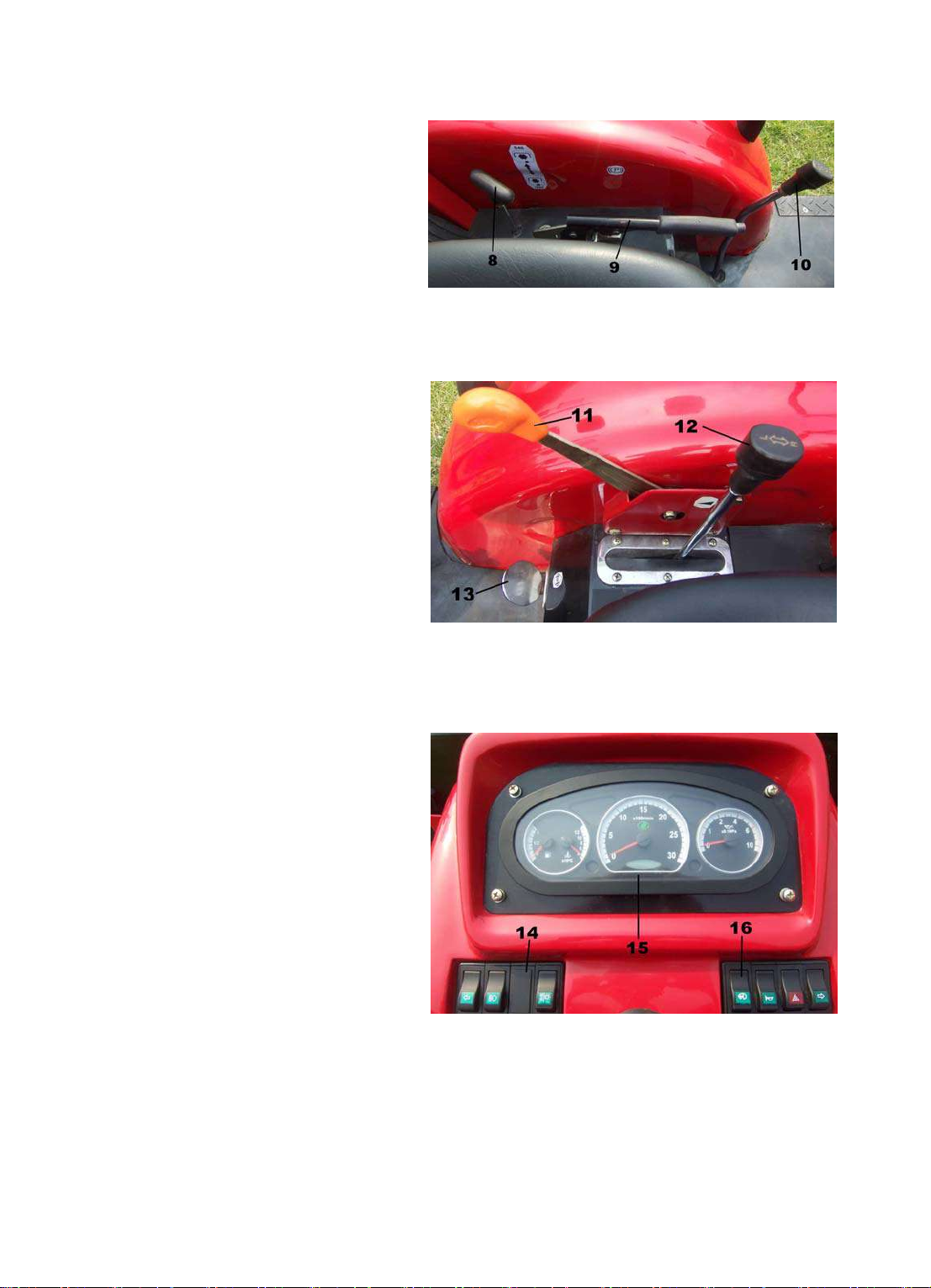
(2)Control Mechanism of Hand Throttle (Fig. 4-3
Parts 11)
Push ahead, and the oil supply will be increased;
pull ha ck, it will be red uced.Hand thro ttle is forb idden
for road traveling.
(3) Control mechanism of foot throttle (Fig. 4-1,
Parts 7)
Step it dow n to increase oil pully; rele ase pedal
to reduce oil supply.
(4)Shut-off control mechanism (Fig. 4-1, Parts2)
Pull the leve r backwa rd an d the en gine w ill be s hut
down. Then the lever will be rush into the original
position for next sta rting.
(5)Clutch contro l mechanism (Fig. 4-1, Parts 3)
Step down the clutch pedal forward for releasing
“
。
“
“
“”
Fig. 4-1 control unit 1
1-preheating starting switch
2- flameout handle
3-clutch pedal 4- assistant
gear-shifting lever
5-key gear-shifting lever 6-
braking pedals
7-foot accel pedal
17
clutch and the pedal to keep the clutch
engaged.
()
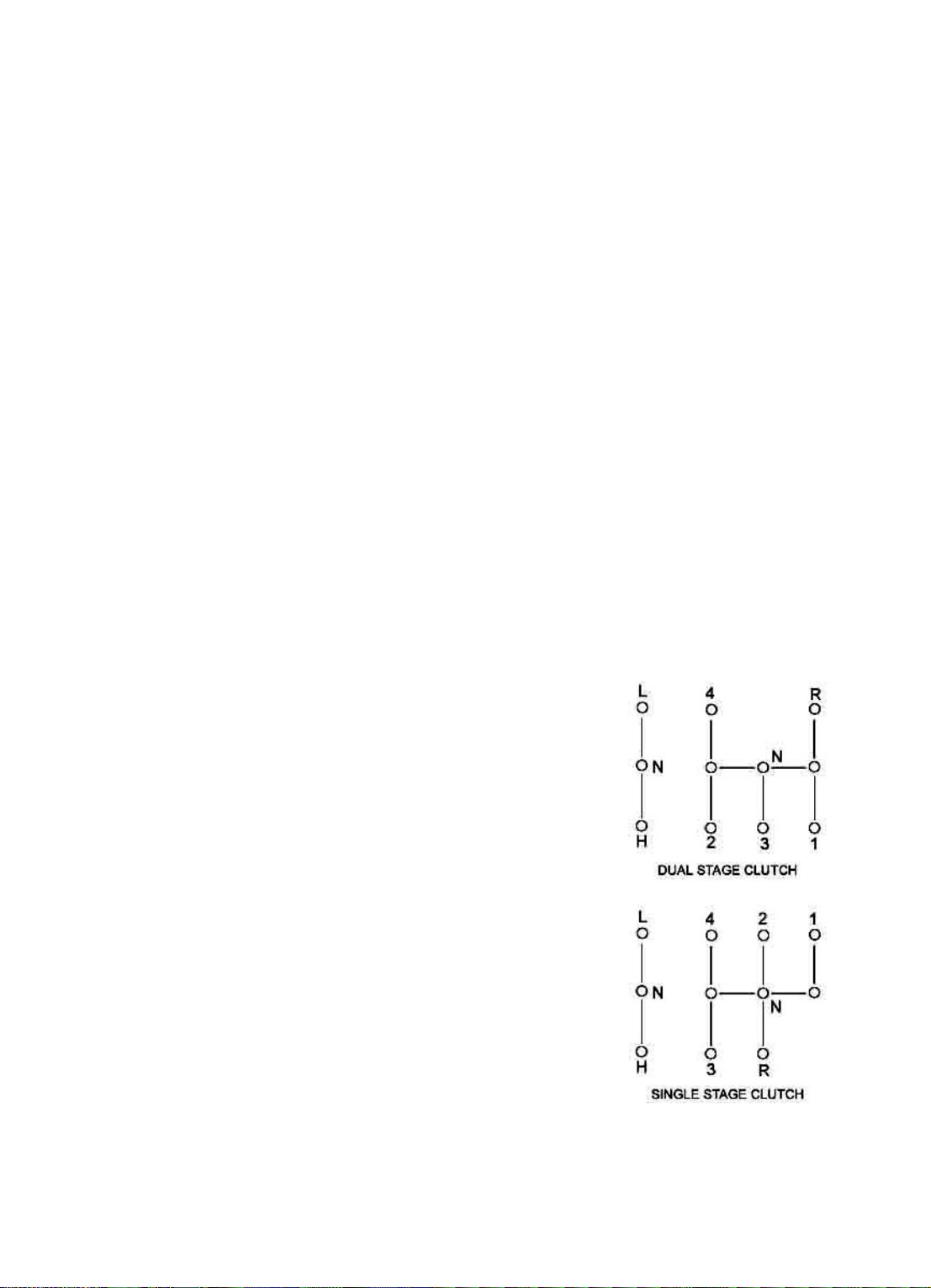
6 Key and assistant gear-shifting
control mechanism (Fig. 4-1, Parts 4, 5)
Control key and assitant gearlevers for
8 forward gears and 2 reverse gears. Before
the key and the assistant gearlevers, clutch
pedal should be stepped down first.
()
7 Control mechanism of foot
brake (Fig. 4-1, parts 6)
Step down left-right braking pedal for
brakin g. Before that, clutch pedal should be
stepped down first. In emergent case,
braking and clutch pedals can be stpped
down at the same time.
()
8 Control mechanism of hand
brake (Fig. 4-2, Part 9)
Pull hand brake handle upward for
emergent braking or park braking. Before
starti ng th e vehic le, check the han d brake to
see if it is in the separated position.
(9) Con trol mechanism o f differentia l
lock(Fig. 4-3, Part 13)
Step differential lock pedal down and
the diff erential gear will lose the di fferen tial
function. After the operation is over,
rerlease the pedal to its original position.
(10) Front driving control mechanism
(Fig. 4-2, Parts 10)
As for 4-WD tr actors, pu sh the contro l
lever forward for 4-wheel driving; pull the
control lever backward, separate 4-WD.
Before oper ation, th e clut ch peda l should be
stepped down first.
(11)Control mechanism of hydraulic
system (Fig. 4-2, Parts 12)
Control modes of hydraulic
suspending system has three types of
combination control, position control and
floatin g control. These are operat ed through
lifter control lever, force-control spring
assemb ly , rig ht press p late of lifting axle, middle ro d w eldment, link lev er, feedba ck li n k an d such ot he r
parts.
8-PTO handle 9-hand braking assembly
14-triad switch 15-combined guag es assembly
Fig. 4-2 control unit2
10-front-driving handle
Fig. 4-3 control unit3
11-hand throttle 12-lifter control
13-differential lock pedal
Fig.4 -4 combined gauges and switches
16-quad switches
18

(12) Control mechanism of PTO (Fig. 4-2, Part 8)
Pull PT O control handle upw ard to reali ze PTO of 540 r/min; pr ess PTO con trol handle d own to
realize PTO of 10 00r/min. M iddle p osition is in saperate d situati on, no PT O. Every tim e the spe ed is
changed, the clutch pedal should be stepped down first..
(13)Combi ned gau ges and switches (Fig. 4-4, Part 14, 15 and 16)
Combine d gauges include oil-p ressure g auge, oil vol ume indicat or, water-t emperature i ndicator,
chronometer, rotation speed gauge, warming light and indicator light.
Combine d sw itch es in cl ude : d ippe d he adlig ht s witch of head lam p, s witch of front tu rn lig hts,
switch of rear turn lights, switch es of the front signal li ght and the front licen se light, the rear sig nal
light and license light, switches of rear working lights, horn button, switch of emergent light.
4.5 Contr ol and Drive
Warn ing:
1. Only after readin g the manual carefully, ca n the driver who has got speci al traini ng and
drivin g license with a full survey record can op erate the tracto r. Tractor can not be opera ted
without license s. Overload is forbi dden.
2. drivers should pay especial attention to the safety & warning symbols and understand
them correctly.
3. It is forbidden to drive tractors after being drunk, tired or taking some an tipsychotic.
4. Don t leave driver s seat to start or control the tractor. Bef ore starting th e tractor,
every gear shift lever should be placed in the position of neutral gear . To get off the tractor,
every gear shift lever should be placed in th e position of neutral gear .
5. Before the tractor moves, its path should be no any barrier, and no people between the
tractor and the rear implement or trailer.
6. Don't g ett in g on o r o ff th e t ra cto r wh en it is running. No re pair o r c he ck und er t he tractor
is allowed when the engine runs. People are forbidden to sit on the fender apron. Casualty
accident can happen when it parks, so parking brake is necessary.
7. To go on an abrupt slope, you d better select a proper gear. It is not allowed to shift
gears on an abrupt slope. When going down the slope, it is forbidden to stop the engine or out-ofgear or turn sharply. For emergency stop, you should step down the clutch pedal and the brake
pedal at the same time. Don t just step down the brake pedal , or some mechanical parts will be
damaged.
8. For transportation operation, the right and the left brake pedals should be locked
together. For high-speed d riving or full-lo ad operation, i t is strictly forb idden to use unilate ral
brake to get a sharp turn.
9. High spee d is no t allowed whe n operatin g or transferrin g to other fie ld with hun g farm
impleme nts. Lift t he workin g units o f farm impl ements out of the e arth to av oid damag es to the
parts of lifti ng s ystem an d su spending s ystem. W hen leaving the trac tor, driver shou ld drop farm
implements to the ground, stop the engine and take off the keys to avoid others starting tractor.
10. For em ergency park ing, you should ste p down the clut ch pedal and br ake pedal at th e
same time. Don t only step down the brake pedal , or the brake will be damaged.
11. D riving on road, you should follow the local traffic rules.
’’
“”
“”
’
’
’
’
19

Attention:
1. Carefully check and listen to the engine and all parts of the tractor when they are working
to see if there are abnormal sound and noise, especially check the technical situations of clutch
and brake, check and tighten the bolts and nuts at every key site of the tractor. Check air
pressure of the tires, aerate the tires if necessary.
2. When the mac hine is turnup d uring op eration , shift to a lo w gear , release t he clut ch and
discharge the load to avoid lengthways turn-over.
3. When en gine is over sp eed , u nl oa din g is no t a llo we d. You d be tte r im m ed iately pul l shutdown lev er, and tu rn th e de com p re ssion rod to th e d ec omp ression po si tion or ke ep air away from
entering engine or cut off the oil way.
4. Watch the color of the exhausted air. Too much black smoke is not allowed to avoid
overload of the engine. If the clutch slides or cannot separate thoroughly or brake doesn t work
well, the machine should be stopped for check.
Operat ions duri ng nights need complete lighting e q uipments.
6. Wh en 4-whe el driv ing tra ctors tr avel with out loa d or ar e engage d in tr ansportat ion, the
front driving lever sho uld be placed in the neutral position.
7. To avo id tur n-ov er, es pec ially tr avel o n st eep sl ope and mu ddy road s. On ly lo w g ear s are
allowed. When going down the slope, it is forbidden to step down the clutch and slide with neutral
gear.
8. To avoid the pollution caused by the exhaust gas don t start the diesel in a room that is
closed witho ut fine ventilat ed conditions. Wh en a diese l transfers, keep hum an and an imals far
away from the exhaust gas.
4.5. 1 Startin g the Engi ne
Before a new shift be gins to wo rk and st art t he e ngine , they shou ld do sh ift tec hn ical m aint ena nce f irs t
(detailed description is below). Dispense its troubles and do the following work before starting the
engine:
1. Release the switch of fuel tank.
2. Pum p t he oil with hands, fill fuel into fuel sys tem, and e xh aust the air in the sy ste m .(T hi s st ep can be
omitte d gener a ll y. )
3. Check and see if every gear shift lever in the neutral position.
4. Hand throttle should be pulled into the position of fully opened .
5. Insert the key into the switch of preheat starting.
6. Turn the dec om pressio n handle t o t he decomp ression po sition ( de com p ression ca n be omitted i n
hot weather)
Finishing the above steps, you can start the engine as the following steps:
()
1 Starting Preheated Machine
Turn the preheat st arting switc h anti-clock wise until you can hear the sound of ig nition and then
return to th e po si tion ON i mmedi ate ly. P ut th e ha nd thro ttle in th e low -spe ed p osi tion. A ttenti on:
If the e ngine has been starte d while th e startin g switch is still kept in the s tarting pos ition, the motor
will be burned in several minutes.
“”
“”
’
’
’
() :
2 Starting Cold Machine
20
Turn t he crank shaft with e ngine cran k handle f or 5-10 roun ds, turn the preheat starting s witch
clockw ise to th e po sition H and sta y the re f or ab out 1 0 sec onds, th en tu rn to the posi tion ST
and stay th ere for 5 secon ds. And then res et the compr ession ha ndle. Afte r ignition, the starti ng switc h
will be re set t o the midd le pos iti on O N and put the ha nd thr ott le to the poiso n of sm all oil sup ply.
Startin g the engine costs ov er 15 second s and the eng ine isn t alive ye t. The storag e battery shoul d
rest for 10 seconds and then have another try to start.
3. When it is hard to start due to a temperature of below 5 , usually you need a engine oil
preheater that will be energized for 15 minutes, fill some 20~30 water , and the engine can be started.
Or you can fill some 80~90 water, discharge switch should be on at the beginning to discharge some
cold wa ter unt i l th e wa te r fro m th e en gi ne is 40~50 and the turn of f t he dis charge swit ch. At the same
time, th e engine oil w ill be heat ed to 60~70 and be filled in to the engi ne (slowly ch urning dur ing
heating ). It is n ot al lowed to br ake the oil pan of the engine with fire, or t he machine bo dy will b e
damaged.
4.5.2 Start to Move
1. Step do wn the clutch pedal thor oughly, and shift the main an d assista nt gear shifti ng levers t o
needed gear steadily and slowly.
2. Relea se the clutc h peda l slow ly and at the same time g radua lly ge ar up to mak e the tr actor star t
movi ng slow ly and stably.
3. Gear selection: Select a proper gear to get a high production and
4.5. 3 Driving Tr actor
1. Turn the steering wheel to get a direction change. Sharp turn is allowed under low gear. singleside braking can be used to minus the turning radius during field operations (especially in paddy fields)
to raise its flexibility and production; however when it operates with
high speeds or transports on roads, single-side braking cannot be
adapte d for shar p tu rn to avo id tur n-ov er. 2. Wh en the tra ctor is en gage d
in transportation or travel on roads, the left and the right brake pedals
should be interlock ed. When th e tractor is par ked, especi ally when it i s
stoppe d o n a slop e, you mus t us e a fixe d ja w to lo ck th e br akes t o av oi d
automatical moving.
3. Gear selection: Select a proper gear to get a high production and
economic performance. See Fig.4-3 for the speeds and uses of every
gear.
I-gear and II-g ear can no t be use d to plou gh and har row, or be use d
as the p ull force. Or th e transmissio n system will h ave severe overload
to avoid damage. During working the tractor should be kept from
overload. Follow the steps below to distinguish:
1). V -gear is adapted for wo rki ng. Put the thro tt l e in the semi-o pen
positio n to let the tractor w ork with loads, and th en push the thrott le to
the fu lly-op en p ositi on. I f now the trac to r spee d is incr ease, it m eans n o
over load, while if it slows down, it means over load.
2). When V-gear is used for working and engine sounds heavy with
black smoke, it means overload. Change to IV-gear. Every time you
shift gears, clutch pedal should be stepped down fully first to avoid breaking gears.
“” “ ”
“”
’
℃
℃
℃
℃
℃
Fig.4-5 gears distribution
21

4.5.4 Parking
g
1. Lower down the gear for a slower moving
2. Step down the clutch pedal and push the main gear shifting lever to the neutral position.
3. Release the cl utch pedal to make th e engine fre ely run with a low sp eed.
4. To red uc e the water temperature an d o i l te m pe rature slowl y, engine sh ould be kept r un nin g for a
while at a slow speed. It is forbidden to stop the engine under a high temperature.
5. Push the hand throttle to the position of closed
6. Pull out the shu t-down lever
7. Turn off the oil tank switch after stopping the tractor.
8. To preve nt the c oolin g water from being frozen in winter that can cause frost crack, you should
turn on the two discharge switches and open the water tank to discharge all the water.
theoretical
gear grade action
F1 rototilling,replanting 2.248(2.082) F5
velocity
()km/h
“”
Table 4-3
gear action
ploughing, harrowing,
and seedi ng
theoretical
velocity
()km/h
10.37(8.867)
F2 rototilling,replanting 3.008(2.628) F6
F3 harvesting 4.127 (4.279) F7 roa d t ransportation 19 .451(18.204)
ploughing,
F4
Speeds in () match si ngle-acting clutch
●
Important:
1. Whe n working in fields or muddy area, you'd better remove the dirt from your shoes and
keep the pedals clean. Catch the armrest careful when getting on or off the tractor.
2. Watch readings of every gauges. During normal operation, engine oil has a pressure
range of 300~450kPa and a water temperature range of 70~90 . When readings on gauges have
malfunctions, repair or replace them. Don't use it any longer.
3. You should tell your next shift about the troubles and malfunctions you found.
4. Try to avoid barrie rs on roads when drivi ng tractors.
5. Driving on roads, farm implements cannot be put into use.
harro w ing, an d
seedin
6.258(6.78 5) F8 road transportat ion 28.86 7(28.86 7 )
ploughing, harrowing,
and seedi ng
℃
13.875(11.182)
4.6 Operation and Use of the Working Units of Tractor
4.6. 1 Operati o n and use of PTO shaft
Rev of PTO shaft is the combination of 540r/min. and 1000r/min
1. Push the cont rol hand le of PTO shaf t to the m iddle neutr al positi on, take down the p rotectin g
cov er of PTO shaft and connect th e worki n g mech anism and PTO shaft.
2. Step d ow n th e clutch ped al to the botto m , pu t th e handle of the driving PTO s ha f t to the position
“”
conjun ction , and the n pu t the h an dl e of P TO sha ft to nee ded gears a cco rd ing to the re qu irements of
workin g mech anism
:
22
 Loading...