


ADO102 \ ADO104 automotive oscilloscope manual
ADO102 \ ADO104 automotive oscilloscope is a portable device developed and
produced by JH Company. This product is compact, portable, and flexible operation;
Using color TFTLCD and pop-up menus to display; to achieve its ease of use, greatly
improving the user productivity.
In addition, this product has superior performance and it is powerful, affordable, high
cost. The real-time sampling rate can be as high as 100MSa/S,can meet the capture
speed, market demand for complex signals and auto repair market; Support for USB
storage devices, users can upgrade via USB, Special test project and Universal
oscilloscope to meet different levels of customer needs.
Characteristic:
Model
Bandwidth
ADO 102
Dual channel
ADO 104
Four channel
—New ultra-thin design, small volume, light weight, convenient carrying
—Color TFTLCD display, 320*240 resolution, waveform display more clearly, stability
—Four analog channel (ADO102 for Dual channel)
—Can be convenient to realize the car corresponding module features one-button
operation
—Any interface screenshot (press F2 screenshot)
—Screenshot can preview
—Support for USB storage device
—Have the edge trigger function, under universal oscilloscope mode can automatically
detect the support (20Hz - 10MHz)
—Support time and voltage cursors
—Support A variety of waveforms mathematical sum
—Adding a variety of waveform math functions
—Support Chinese and English menu display
—A variety of display styles
—Backlight brightness can be adjusted
—Long standby: single cell battery can work continuously for 5 hours
—With a digital multimeter functions
General safety requirements:
The following safety precautions to avoid injury; And to prevent the product or any other
products connected from the damage. To avoid possible danger, be sure to use the

product in accordance with the provisions.
Attention: Do not using this oscilloscope (or multimeter)
measurements while connecting USB, as this may damage the
instrument!
Only trained personnel should perform service procedures.
1. Avoid fire and personal injury
● Correct plug
When the probe or test leads are connected to a voltage source Do not plug.
● Properly connected probe
The same probe wire and the ground potential,Do not connect the ground wire to a high
voltage. And during the test, do not touch exposed contacts and components.
● View all terminal ratings
In order to avoid the fire and impact of excessive current, Please check all rated the
product value and marking instructions. Please refer to the product description before
connect the products for more information about ratings.
● Do not open lid
If the cover or panel has been removed, do not operate this product.
● Avoid circuit exposed
After the boot, Do not touch exposed connections and components.
● Suspected product failure, do not operate
If you suspect that the product has failed, you can ask a qualified service personnel.
● To maintain adequate ventilation
● Do not operate in wet conditions
● Do not operate in the flammable, explosive environment
● Please keep the product surface is clean and dry
2. Security terminology and labeling
Terminology in this manual. The following terms may appear in this manual:
Terms on the Product: These terms may appear on the product
DANGER: Indicates that there is a direct risk of harm exists near the mark.
WARNING: Indicates a potential risk of injury near the mark.
Note: indicate a potential danger to the products and other property.
Symbols on the Product: These symbols may appear on the product
High voltage Protective ground Attention Measurement of ground
WARNING: Warning statements indicate conditions and
behavior which might endanger the safety of life .
Note: Note Statement Pointed out conditions and
behaviors that may cause this product and other
property damage .

Summary:
This manual describes the operation of ADO Series Handheld Digital Oscilloscope.
Manual includes the following chapters:
◆ Getting started: a brief introduction to digital handheld oscilloscope's front panel user
interface, functional check and probe compensation.
◆ Features and Operation: a detailed presentation for functions and operations of
universal oscilloscope and automotive oscilloscope and multimeter.
◆ The application example: provide some measurement example, for reader reference.
◆ System Tips and Troubleshooting.
◆ Service and Support
◆ Appendix

1
Catalog
Chapter 1 Getting Started .............................................................. 2
1.1 Preliminary understanding ADO front panel and user interface ............................ 2
1.2 Probe ...................................................................................................................... 3
Chapter 2 Describes of the function and operation ........................ 4
2.1 Automotive oscilloscope ......................................................................................... 5
1. Quick Operation Guide ...................................................................................... 5
2. Ignition function ................................................................................................. 5
3. The function of sensor ..................................................................................... 13
4. The Function of Actuator ................................................................................. 19
5. Bus .................................................................................................................. 22
2.2 Universal Oscilloscope this section features are described ................................ 23
1. Menus and Control buttons ............................................................................. 24
2. Connector ........................................................................................................ 25
3. Automatically set ............................................................................................. 25
4. Default settings................................................................................................ 26
5. Vertical Systems .............................................................................................. 26
6. Horizontal Systems ......................................................................................... 27
7. Trigger system ................................................................................................. 28
8. Math System ................................................................................................... 29
9. System Setup .................................................................................................. 30
10. The storage system ....................................................................................... 31
2.3 Multimeter function and operation ........................................................................ 32
Chapter3 Application Examples ................................................... 34
3.1 Singal measure ..................................................................................................... 34
3.2 Cursor measure .................................................................................................... 34
3.3 Capture the Single Signal..................................................................................... 35
3.4 Use Multimeter to Measure DC Voltage .............................................................. 36
Chapter 4 System Tips and Troubleshooting ............................... 36
4.1 Prompting Message ............................................................................................. 36
4.2 Troubleshooting .................................................................................................... 36
Chapter 5 service and support .................................................... 37
5.1 Warranty Description ............................................................................................ 37
Appendix A: Technical Specifications ........................................... 37
Appendix B: ADO 102/ADO 104 oscilloscope accessories .......... 39
Appendix C: routine maintenance and cleaning .......................... 39

2
Chapter 1 Getting Started
ADO handheld digital storage oscilloscope is a small, lightweight portable instrument,To
provide users with a convenient and easy to operate front panel, you can perform basic
tests.
This chapter explains how to perform the following tasks:
△ Preliminary understanding ADO front panel and user interface
△ Probe Compensation
△ Match the probe attenuation factor
1.1 Preliminary understanding ADO front panel and user interface
Before using ADO, We must first understand the operation panel. Following is a easy
description and presentation for the ADO series front panel operation and function, To
make use of you in the shortest possible time familiar with the oscilloscope.
ADO provide users with a clear and simple front panel, To facilitate the user to perform
basic operations. On the left and right side of the display panel is marked with various
function keys. Key to set the different options up and down through the menu. The red
substrate power button, press it, you can open the oscilloscope or shutdown. The other
pushbuttons are function buttons, through them, you can enter different function menus or
obtain a specific function application. As shown in Figure 1-1 and Figure 1-2.
Figure 1-1 ADO102 Figure 1-2ADO104
Channel 1-2
F1-F4
multi-selector
button
Channel1-4
RUN/STOP
Multimeter
Back
Move button
Zoom button
3
Figure 1-3 Interface is shown in Figure
1.2 Probe
1 Safety of probe
Set around the probe body protection to protect your fingers to prevent electric shock.
Before taking any measurements, make sure the probe is connected to the oscilloscope
and the ground terminal to ground.( Note: The oscilloscope probe and the attenuation
must be set the same gear)
2 Probe compensation (see probe manual)
In the first probe with any input channel connection, this needs to be adjusted to match the
probe to the input channel. Uncompensated probe calibration can cause measurement
error or errors. If you adjust the probe compensation, as follows:
(1) Set the Probe option attenuation to 10X in the channel menu, The switch on the probe
is also set to 10X,And oscilloscope probe connected to channel 1.If using the probe
hook-tip, ensure reliable contact with the probe.
(2)Connect the probe tip and the signal generator output connector, Grounding clip and
signal generator is connected to the ground connector, Display Channel, Then press the
"AUTO" (automatic) button.
(3)Check the shape of the waveform display. As Figure 1-4
Trigger
status
display
Channel 1 mark
Show vertical
volts / division
Display power
Horizontal
displacement
Show the amount of
the trigger position
Channel
operation
status
Show
horizontal
time / div
Display
level
Trigger
position
Corresponds to a different
function keys, menus will
vary
Frequency
waveform display

4
Under compensation Appropriate compensation over compensation
Figure 1-4
(4) If necessary, adjust the probe and repeat the operation if necessary.
Chapter 2 Describes of the function and operation
In order to use ADO Series oscilloscope effectively, you need to understand the main
functional framework of the oscilloscope.
This chapter is divided into three modules to introduce oscilloscope according to the
functional framework: automotive oscilloscope, general oscilloscope, multimeter.

5
2.1 Automotive oscilloscope
This section function of automotive oscilloscope is described below:
Ignition Sensor Actuator Bus
1.Primary
ignition
2.Secondary
ignition
3.Primary and
secondary
ignition
4.Primary
ignition
(current)
1. Crankshaft and
camshaft position
2. Vehicle speed
sensor
3. Oxygen sensor
4. Throttle position
sensor
5. Air flow meter
6. Manifold absolute
pressure
7. Knock sensor
8. Accelerator pedal
1. Electromagnetic
valve
2. Gasoline and
diesel fuel nozzle
3. Gasoline nozzle
(Current)
4. Gasoline nozzle
(Voltage and
Current)
1. CAN-high、
CAN-low
2. LIN-bus
3. FlexRay
NOTE: When signal voltage of measured signal is not clear, you can use multimeter first
(this series oscilloscopes are with multimeter), according to the measured value of the
multimeter, set the attenuation ratio of the oscilloscope and probe. The waveform pictures
of each functional test in text are from Dodge. Journey 2.4 L model cars, different models
measured different waveforms, so there will be differences.
1. Quick Operation Guide
Setting essentials:
1)Wave height adjustment (amplitude):Press the corresponding channel, and adjust
through the up and down keys
2)Waveform overall move:Press the corresponding channel, and then adjust through
the left and right keys
3)Waveform density adjustment (time base):Press time base key, and then adjust
through the up and down keys
4)Waveform shaking elusive:Press the trigger button, and then by moving left and right
keys, and then control the trigger arrow in the right of the screen, move red trigger arrow
to the appropriate location of waveform until the waveform stabilizes
5)Waveform freeze playback view: Press the start / stop button, then press the time
base key, and finally by moving left and right key to see if crankshaft has missing teeth
phenomenon
2. Ignition function
(1)Ignition introduction
1)Ignition System Category
6
Partakers boards conventional ignition system used on the car has a long history,
now has gradually been replaced by direct ignition system (DIS)
Direct ignition system is divided into three types:
▲dual ignition system using double-ended output ignition coil (DEC).
▲single ignition system using single-ended output ignition coil (CPC).
▲Integrated ignition system using the integrated spark plug (COP).
The common feature of these three is the output of the ignition coil pass directly
to the spark plug without passing through the distributor plate
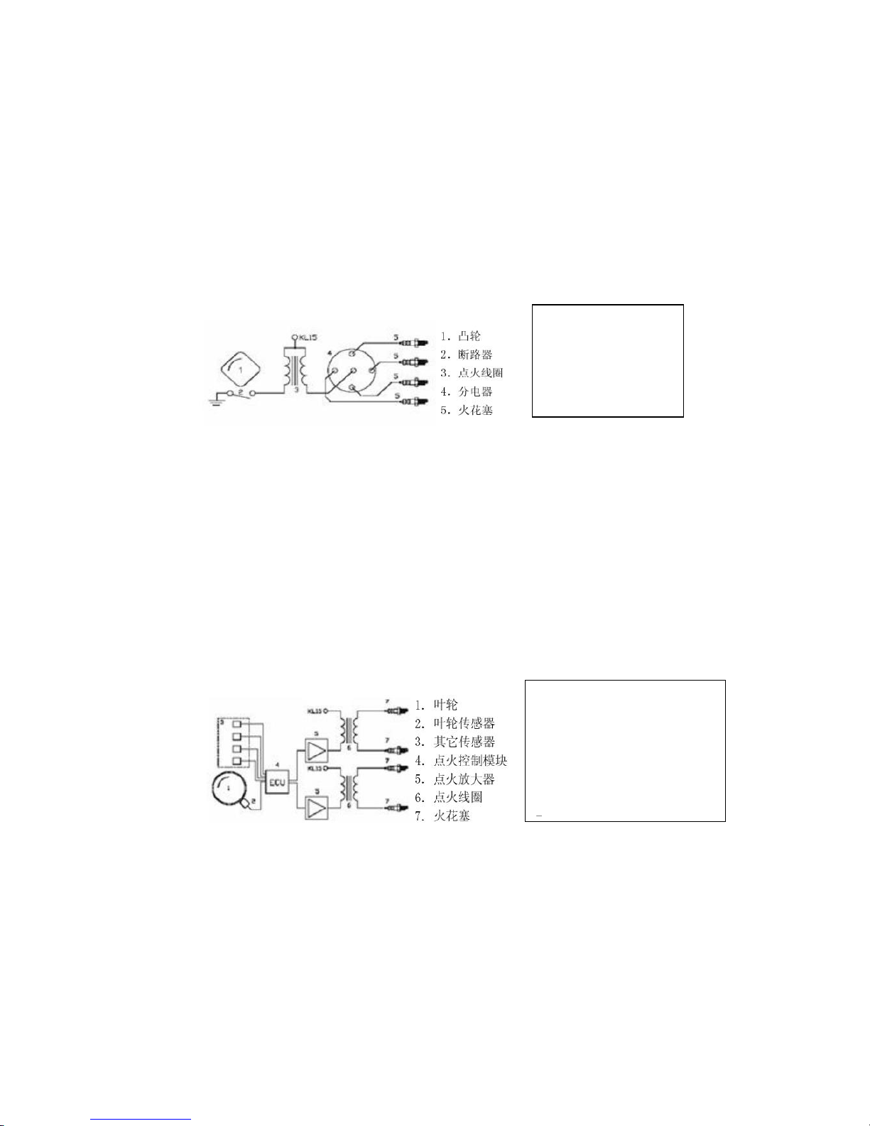
2)Traditional ignition system
Traditional ignition system consists of a battery, cam, breaker, ignition coil, distributor,
spark plugs. The effect of battery is to supply power of the ignition system require, cam
and the circuit breaker turn on or off ignition system power. Ignition coil store ignition
energy and turn battery voltage to ignition high voltage. The role of the circuit breaker is
turned on or off ignition primary circuit. The role of the distributor is to delivery ignition high
voltage produced by ignition coil to each spark plugs according to working order of engine.
Spark plugs lead ignition high voltage to cylinder combustion chamber, and produce spark
between the electrodes, Igniting the combustible mixture.
The advantage of this ignition system is relatively easy for detection service, one of
the disadvantage is mechanical parts and electrical contacts easy to wear, short life. And
the high-voltage connector portion also easily damaged.
3)Dual ignition system (DEC)
Dual ignition system entirely by electronics, with no mechanical parts. Each two
cylinder shared a ignition coil, two electrodes of coil secondary connect to a spark plug
respectively. It means that there are always two spark plugs igniting at the same time, one
of the cylinders in the normal ignition, the other cylinder is at the exhaust process (Ignition
spark "waste" in the exhaust gas), the pressure of cylinder in exhaust close air pressure,
only need very low ignition voltage, wasted little energy.
One of the advantages of dual ignition system is fewer faults, virtually no maintenance.
Another advantage is the good adjustability of the ignition system; wave radiation emitted
1. Cam
2. Breaker
3. Ignition coil
4. Distributor
5. Spark plugs
1. Impeller
2. Impeller sensor
3. Other sensor
4. Ignition control module
5. Ignition amplifier
6. Ignition coil

7
small, low fuel consumption. The disadvantage is still required high voltage and spark plug
connector, these places is very easy to go wrong.
4)Single Ignition System (CPC)and Integrated ignition system (COP)
Each cylinder has a separate ignition coil, is today's most advanced ignition system.
This ignition system is divided into two types: Single Ignition System (CPC), integrated
ignition system (COP). Integrated ignition system integrated ignition coil in the spark plug,
single ignition system is connecting ignition coil to spark plug with a high voltage wire.
5)Ignition principle
▲The electronic ignition
The electronic ignition system collect information related to the engine with a set of
sensors, such as speed, cooling temperature and engine load, etc. Position sensor and
speed sensor is the most important information required for the ignition system, the
information from the wheel sensors or camshaft sensor. Ignition control module calculates
ignition time and charging time based on the collected information, If a sensor is not
working properly, it will cause the output signal is incorrect, so modern control module
have to check whether the signal sent by the sensor is authentic, when there are
untrusted signal, it may not output any signal. Ignition control module output signal can not
directly drive the ignition coil, have to amplify by ignition amplifier. In fact, ignition amplifier
is mounted in ignition coil generally, in this case the primary ignition signal is
undetectable;Or mounted in the ignition control module,in this case the ignition control
module output signal is undetectable. Thus, detecting engine fault and performance
through the secondary ignition signal is important.
▲Mechanical ignition system
1. Impeller
2. Impeller sensor
3. Other sensor
4. Ignition control module
5. Ignition amplifier
6. Ignition coil
7. Spark plugs
1. Signal sensor
2. Ignition control module (ECU)
3. Ignition amplifier
4. Ignition coil
5. High voltage line and spark
plugs

8
Contact-driven
Sensor-driven
In the mechanical ignition system, the charging time and the ignition time is
controlled by the distributor camshaft. Electrical sensor (Hall or magnetic) or contacts is
as the role of the sensor. Contacts can directly drive the ignition coil, but telex can only
drive the ignition coil by ignition enlarge. In fact, ignition amplifier is mounted in ignition
coil generally,in this case the primary ignition signal is undetectable.
6)Sensor
Hall devices and magnetic induction coil are commonly used sensors.
Hall device output square wave 0-5 volts or 0-12 volts.
Magnetic induction coil output sine wave, the amplitude is related to rotational
speed. Ignition control signal.
Ignition control module output control signal 0-5 V or 0-12 V square wave.
7)Secondary ignition
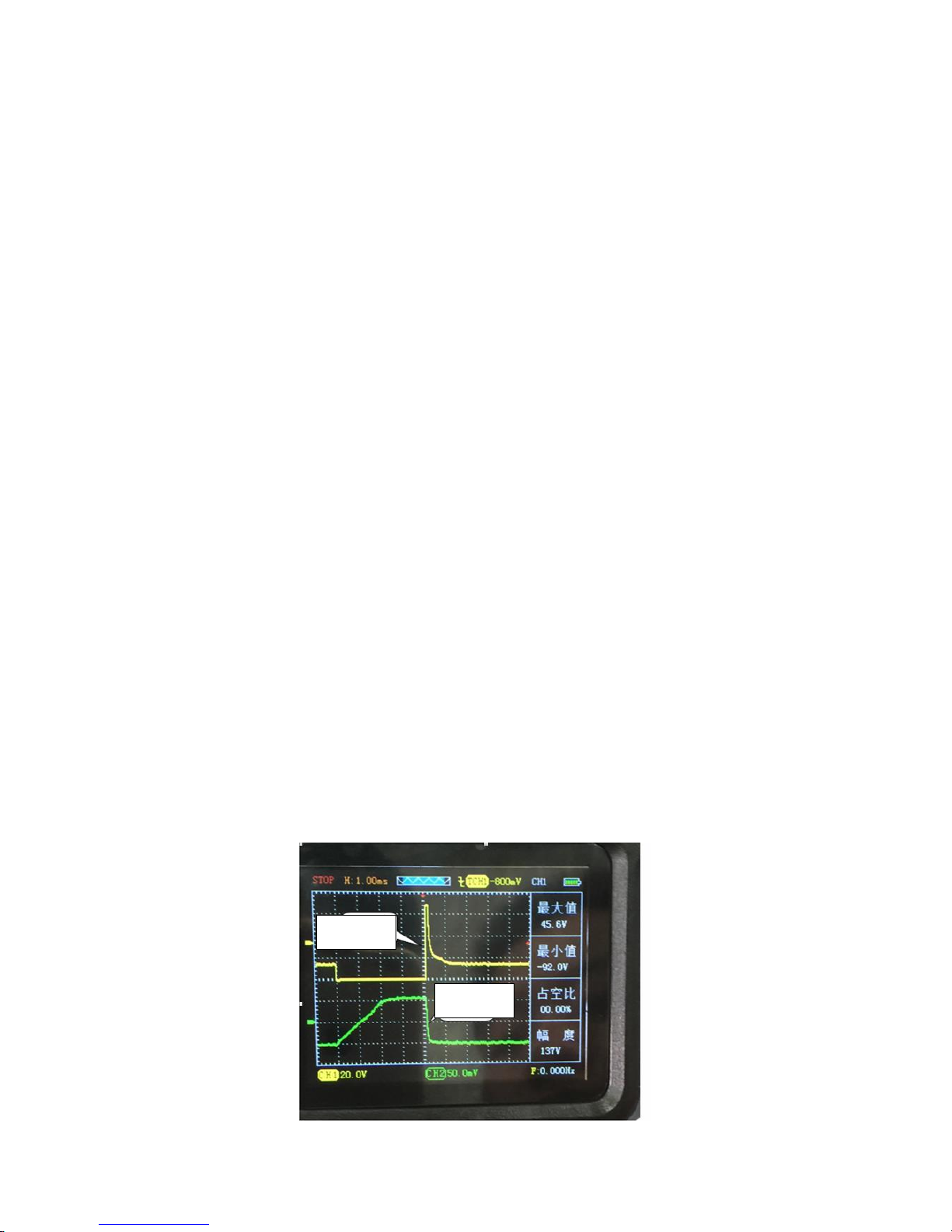
When ignition, coil secondary generates a high voltage,when the voltage is
gradually increased to a certain value,the spark plug produce sparks,this voltage is
the ignition voltage. The voltage then drops rapidly to another voltage value and
maintained for some time,this voltage is the
combustion voltage, combustion time is the
time of voltage maintained at a combustion
voltage value. At the end of the burning time,
ignition coil energy is almost exhausted, the
remaining energy is formed damped
oscillation on the coil.
Observing this picture can analysis of
operation of the vehicle from details. Ideally,
this pattern is very stable, showing each
voltage of ignition combustion processes are
1. Electric shock
2. Ignition coil
3. Distributor / high voltage line /
spark plugs
1. Sensor
2. Ignition amplifier
4. Ignition coil
5. Distributor / high voltage line /
spark plugs
Closed section
Flashover segment
Shock attenuation
section

9
the same. Each cylinder pattern should be roughly the same. However, the actual
situation is not ideal, graphics assembly will be large or small jitter,such as ignition
or breakdown voltage fluctuated,combustion times may vary in length,these do not
necessarily indicate the engine failure. These may need us have experience
cumulation by time, combined with a comprehensive analysis of other graphics,but it
can be said, the ideal graphics may not been seen.
Ignition or breakdown voltage:If the ignition voltage is too high, even more than
the range of the screen, indicating that the resistance value is too high in secondary
ignition circuit. Open line,spark plug damaged,high-voltage or spark plug gap is too
large may have resulted in the phenomenon of high breakdown voltage,Conversely,
if the breakdown voltage is too low,It indicates that the resistance value in ignition
secondary circuit is lower than normal, spark plugs may be dirty or rupture,
high-voltage leakage and other reasons caused.
Combustion line and combustion time:if combustion line has too much clutter,
It represents cylinder misfire. Or due to premature ignition, injectors damaged, spark
plugs dirt and other reasons. The length of the combustion line duration is related to
mixed gas concentration in the cylinder. Typically, it means that the combustion time
exceeding 2ms gas mixture is too thick. Conversely, if combustion time is less than
0.75ms indicates too lean mixture.
8)Correct broken-line by broken wire needle.(all need to break the wire for
measurements except for secondary ignition)

10
(2)Ignition test
cross section of ignition coil(inside is secondary coil outside is
primary coil)
1)Primary ignition
①After the oscilloscope installed batteries,long press red power
button“ ”, let it go until you hear the buzzer,at this time
oscilloscope enter the main menu interface,as picture-1
②After entering the main menu interface , can select the
instrument operation mode through the up and down buttons,
then press “OK” button,default select the "ignition" into the ignition
function selection interface,then you can enter the user interface through up and
down keys to select the "primary ignition", as picture-2
③Connect the probe to CH1 and probe set to 10X,then connect
grounding clip to the signal ground or grounding.
④Since the primary ignition of oscilloscope has default settings
(Probe 10X,time base 1ms), Simply connect the ignition coil
to the probe needles can display waveform. As picture-1(when
the waveform shaking too fast to capture, you can set the trigger
Mode to single-shot then detect again)
⑤Press“CH1”,can view the values and configuration(configuration has default)
Picture-1
Picture-2

11
⑥Waveform display can be adjusted based on their own through the vertical
volts / division and trigger ways to meet your needs(Time base, vertical volts /
division and other specific operations, please refer to the operation of general
oscilloscope)
2)Secondary ignition
①Same as Primary ignition step 1
②After entering the main menu select "Ignition",then enter the sub-menu press
the up and down keys to select "secondary ignition",It will prompt "use
professional ignition probe" before entering the operating interface, wait a few
seconds to enter the oscilloscope interface.
③Independent ignition to be equipped with an ignition extension cord and high
voltage ignition probe must ignition sensing probe, connect ignition probe to
CH1.
④Since the secondary ignition of oscilloscope has default settings(Probe 10X,
time base 1ms)ignition system with sub-cylinder line, probe with capacitor
(small black squares )side is sandwiched with sub-cylinder line, the other side
connected to the ground or battery negative. If the car is an independent
ignition system,you need to buy "independent ignition extension cord"(one
side connect to ignition coil, one side connect to spark plug, the role is to
replace the sub-cylinder line)ignition probe in independent ignition extension
cord, Step as above.
⑤Same as Primary ignition step 5
⑥Same as Primary ignition step 6
3)Primary and secondary ignition
This function let the primary ignition, secondary ignition be realized through CH1
and CH2,observed and compared two waveforms more intuitively. Select”
Primary ignition, secondary ignition” Before entering into operation interface, it
Breakdown voltage
or ignition voltage
peak
arcing or burning
voltage
Burn line
Ignition coil begins
charging
Oscillation coil
Pic-1 Primary ignition

12
will prompt“CH1: standard probe for primary use,CH2: Ignition probe for
secondary use” Wait a few seconds to enter the oscilloscope interface,other
details, please refer to the above primary, secondary ignition function.
Note:CH1 is primary ignition, CH2 is secondary ignition pay attention to the
probe connected to the channel
4)Primary ignition (current)
①Same as Primary ignition step 1
②After entering the main menu select "Ignition",then enter
the sub-menu press the up and down keys to select the
"primary ignition (current)",before entering the operating
interface, it will prompt "must comply with the current
clamp using" wait a few seconds to enter the
oscilloscope interface.
③Connect current clamp to the oscilloscope CH1, since the
primary ignition oscilloscope is default setting (probe 1X,
time base 1ms), simply connect the current clamp to ignition
coil, then waveform can be visually displayed. As pic-2.
④Press“CH1”, you can view the value and configuration
(configuration has default)
⑤Displayed waveform can be realized through the self-regulating
group, vertical volts / division and trigger their needs
(time base, vertical volts / division and other specific operations,
please refer to the general oscilloscope operation)
Note: If the measured waveform inversed, change the direction of current clamp as
pic-3, the specific use of current clamp, please refer to the purchase
Instructions of the current clamp (To purchase current clamp can contact the
manufacturer for recommended)
Pic-2 Primary ignition current
Pic-3 use of current clamp
13
3. The function of sensor
1)Crankshaft and camshaft position sensor(magnetic-electric, Hall)
①After the oscilloscope installed batteries,long press red power
button“ ”,let it go until you hear the buzzer,at this time
oscilloscope enter the main menu interface, as picture-1
②After entering the main menu interface select “Sensor”, then
enter the sub-menu press the up and down keys to select
"Crankshaft and camshaft position sensor"(as picture-2),
enter the second sub-menu press the up and down keys to select "Magnetic
Electric"or" Hall ", press “OK”,
it will separately prompt "Amplitude with the speed of change"
and "0-5v or 0-12v" before entering operation interface, will
enter into oscilloscope interface after waiting several
seconds.(Note: Channels should be correspond with functions.
CH1: Crankshaft position sensor, CH2: Camshaft position
sensor)
③Connect two probes to CH1 and CH2 separately, and set probe
to 1X, then connect grounding clip to signal ground or grounding.
④Since the "magnetic-electric" and "Hall" function of oscilloscope has default
settings (probe 1X,time base 10ms),just need to connect two probes to corresponding
signals, then the waveforms can be displayed, as pic-4.( measured waveform is under
800 rpm)
⑤Press“CH1”or“CH2”, can view the values and configuration(configuration has
default)
⑥Displayed waveform can be realized the need through the self-regulating time base,
vertical volts / division and trigger type
(time base, vertical volts / division and
other specific operations, please refer to
the general oscilloscope operation)
Note: Considerations when
measuring magnetic-electric and
Hall waveforms
① Measuring range :
Magnetic-electric type time
base 1ms-500ms(Horizontal
ruled); voltage 500mv-50v
(vertical ruled); Hall type
time base 1-500ms
( Horizontal ruled) voltage
1v-10v(vertical ruled)
② The amplitude and frequency
of magnetic-electric type
Picture-1
Picture-2
pic-4 Crankshaft, camshaft position sensor
(Hall)
Crankshaft
Camshaf
14
changes with the speed(Similar with the principles of the generator), the
amplitude with fixed frequency of Hall type changes with the speed.
2) The vehicle speed sensor (magnetic, Hall,
photoelectric)
①The same as the crankshaft, camshaft position sensor
Step 1.
②Select "Sensor" after entering the main menu, then
enter the sub-menu press the arrow keys to select "speed
sensor" into the second sub-menu press the arrow keys to
select "magnetic-electric", "Hall" or "photoelectric", press
"OK" button to confirm to enter the oscilloscope user
interface (Note: before entering the electric and magnetic
Hall oscilloscopes prompts are "amplitude variation with
speed" and "0-5v or 0-12v" wait a few seconds to enter the
user interface )
③Connect the CH1 probe to the oscilloscope and set probe to 1X file transfer, then
connect the grounding clip to the signal ground or grounding.
④Since the oscilloscope "magneto electric", "Hall" and "photoelectric" function has
already default settings (magneto electric and HALL: Probe file 1X, time base 5ms,
photoelectric probe file 1X, time base 25ms), Just probe to the corresponding signal, To
intuitive display waveforms, as shown in Figure 5.
⑤Press "CH1", you can view the value and configuration (by default)
⑥waveform can be self-fulfilling their needs by adjusting the time base, vertical volts /
division and trigger mode (time base, vertical volts / division and other specific operations,
please refer to the Universal oscilloscope operation)
3) The oxygen sensor (zirconium-type, titanium type)
①The same as the crankshaft, camshaft position sensor Step 1.
②Select "Sensor" after entering the main menu, then enter the sub-menu press the arrow
keys to select "oxygen sensor" into the second sub-menu press the arrow keys to select
"zirconium-type” or "titanium type", press "OK" button to confirm to enter the oscilloscope
user interface.
③Connect the CH1 probe to the oscilloscope and set probe to 1X file transfer, then
connect the grounding clip to the signal ground or
grounding.
④Since the oscilloscope "Zirconium" and
"titanium" function has default settings (profiles
probe 1X, time base range 1s), just probe to the
corresponding signal, To intuitive display
waveforms, as shown in Figure 6. (Note: As in the
"SCAN" scan mode requires patience waveform
scanned)
⑤Press "CH1", you can view the value and
configuration (by default)
Pic-5 Hall speed sensor
Pic-5 Titanium oxygen sensor (idle condition)

15
⑥waveform can be self-fulfilling their needs by adjusting the time base, vertical volts /
division and trigger mode (time base, vertical volts / division and other specific operations,
please refer to the Universal oscilloscope operation)
Note:
The oxygen sensor, also known as the exhaust gas sensor, is a very important role in the
exhaust emission control of a vehicle equipped with a catalytic converter.
The oxygen sensor is arranged on the exhaust pipe and in front of catalytic converter. The
variation range of the voltage of the zirconium oxygen is 0-1V, and the voltage variation
range of titanium oxide is 0-5V, because the titanium oxygen sensor needs the power
supply voltage. A vehicle equipped with an oxygen sensor is referred to as a "closed loop",
meaning that the sensor will analyze the exhaust gas and re adjust the engine oil supply
according to the results after the fuel is burned.
No matter how many connection lines between the oxygen sensor and the engine control
module, the sensor output is always a black line.
Single Line: This line is used to produce the output voltage of the sensor itself, usually
black.
Two lines: one output line output and a ground line.
Three lines: one output line and two-line heating device (power line and ground line).
Interior heating means to raise the temperature at cold start to make the cars quickly
brought under control.
Four-wire: a signal line and a signal ground. Two other heating device lines.
Zirconium oxygen sensor needs to reach more than 300 degrees Celsius temperature in
order to work properly, this kind of oxygen sensor normal output feedback voltage change
between 0 ~ 1V. 0.5V above the output indicates that the mixture is too thick; 0.5V output
indicates that the appropriate balance between lean and too thick; 0.5V the following
output indicates that the mixed gas is too thin. The output voltage variation indicates that
the engine control module changes the air fuel ratio
(the ratio of air to fuel, the concentration of the mixture).
Normal zirconia’s oxygen sensor output voltage
waveform should meet the 3 elements: the maximum
voltage, the minimum voltage, response time (voltage
from high to low change of time). In general, the
allowable range is the maximum voltage value > 850mV,
the minimum voltage is 75 ~ 175mV, and the response
time is less than 100ms. For the change of the amplitude
of the waveform is in the idle state of the 10s amplitude
of the waveform is not less than 8 times as shown in
figure 7.
Start the engine and keep the engine speed
1500-2000rpm, after 3 minutes, until the engine reaches
normal working temperature, because the engine must
reach normal working temperature and into the closed
loop, oxygen sensor signal readout instrument is
correct.
Pic-7 Zirconia oxygen sensor
Note: 1、The axis is a peak-to-amplitude
2、Peak to trough for the two amplitudes,not one
Wavelength
Amplitude
Amplitude
One amplitude
16
If the oxygen sensor is detected, the oxygen sensor has power supply, but not see the
waveform change, then the cause of the failure may be as follows:
● poor connection
● oxygen-sensor fault
● engine vacuum leak
● poor fuel mixture ratio control
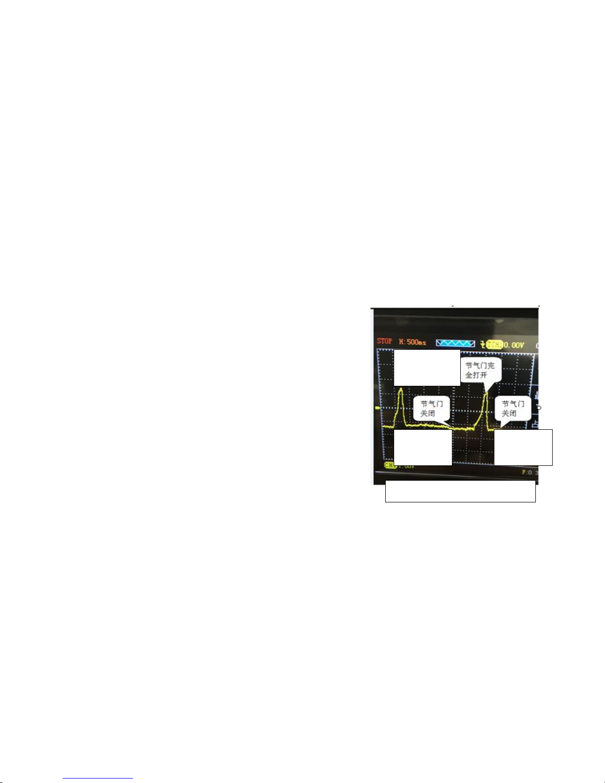
4) Throttle Position Sensor
①The same as the crankshaft, camshaft position sensor Step 1.
②Select "Sensor" after entering the main menu, then enter the sub-menu press the arrow
keys to select "Throttle Position Sensor”, press "OK" button to confirm to enter the
oscilloscope user interface.
③Connect the CH1 probe to the oscilloscope and set probe to 1X file transfer, then
connect the grounding clip to the signal ground or grounding.
④Since the oscilloscope "throttle position sensor" function has already default
settings (profiles probe 1X, time base range 500ms), just probe to the
corresponding signal, to intuitive display waveforms, as
shown in Figure 8. (Note: As in the "SCAN" scan mode
requires patience waveform scanned)
⑤Press "CH1", you can view the value and configuration
(by default)
⑥waveform can be self-fulfilling their needs by adjusting
the time base, vertical volts / division and trigger mode
(time base, vertical volts / division and other specific
operations, please refer to the Universal oscilloscope
operation).
Note:
Open the ignition switch, do not start the engine, to detect
the throttle position sensor signal, slowly open to close the
throttle, observe the waveform has no sudden or irregular
changes in the situation. When the throttle position sensor is analyzed, it is possible to find
out the abnormal signal waveform in any signal waveform, for example, the instantaneous
voltage drop may indicate the error of the sensor itself, damage, or dirty. And this
abnormal signal waveform, but also easy to cause the error of the oscilloscope, so that the
vehicle fault. Most of the solar term door position sensor, when idling, the voltage value
should be all below 1.25V, and the throttle valve is fully open, the voltage value should be
more than 3.4V, and the voltage should be smooth without any change, or surge voltage
drop situation.
When the ignition switch is turned on, the engine does not start, detecting the throttle
position sensor signal, if not see the waveform with the throttle opening variation, the
failure may be as follows:
● poor connection
● bad sensor itself
5) Air flow meter sensor
Pic-8 Throttle Position Sensor
The throttle
fully open
Throttle
Close
Throttle
Close

17
①The same as the crankshaft, camshaft position sensor Step 1.
②Select "Sensor" after entering the main menu, then enter the sub-menu press the arrow
keys to select "air flow meter sensor" into the second sub-menu press the arrow keys to
select "high frequency" or "low frequency", press "OK" button to confirm to enter the
oscilloscope user interface.
③Connect the CH1 probe to the oscilloscope and set probe to 1X file transfer, then
connect the grounding clip to the signal ground or grounding.
④Since the oscilloscope "air flow meter sensor" function has already default settings
(High Frequency: Probe file 1X, time base range 100us, low frequency: probe profiles 1X,
time base range 10ms),Just probe to the corresponding signal, To intuitive display
waveforms, as shown in Figure 8. (note: As in the "SCAN" scan mode requires patience
waveform scanned)
⑤Press "CH1", you can view the value and configuration (by default)
⑥waveform can be self-fulfilling their needs by adjusting the time base, vertical volts /
division and trigger mode (time base, vertical volts / division and other specific operations,
please refer to the Universal oscilloscope operation).
Note:
air flow meter is generally divided into analog air flow meter and digital air flow meter:
●Analog air flow meter
The function of the air flow meter is to measure the air flow into the throttle valve. The air
flow into the throttle valve is different with the speed of the engine. Analog air flow meter
will detect the flow of air into the change of 0-5V between the voltage signal transmitted to
the oscilloscope. Start the engine, step on the accelerator pedal, then the air flow signal,
should be with the throttle valve opening bigger and the higher the value.
In the idle speed should be kept stable, when the throttle valve is fully open, the signal will
be increased to the maximum value.
Watch the waveform signal in the abnormal phenomenon, such as: if the waveform
smoothly, no surge occurred suddenly, waveform distortion, usually said oscilloscope
between sensor and circuit, has the situation bad, bad line or the sensor itself.
Sensor voltage output signal, usually at idle speed when the minimum and with the
increase of the engine load, the average idle speed is about 800mv, when the throttle
valve is fully open, about 4.5V.
● Digital air flow meter
The function of digital air flow meter is to measure the air flow into the throttle body. Air
flow into the throttle body varies with the speed of the engine. Digital air flow meter
converts the detected air flow into the frequency signal. When the higher frequency signal,
the greater the amount of air. Start the engine, at this time will be displayed on the screen
square wave graphics, without any waveform display. You may have entered the analog
air flow meter.
The observed signal waveform anomalies, for example, whether a square wave at right
angles to change, or whether the surge occurs and the like. Sensor signal waveform
sudden change in frequency usually indicates that there is a bad contact between the
oscilloscope and the sensor, or the sensor itself is poor.
Digital waveform generated by air flow meter square wave signal neat, when the ignition
18
key is turned on and tap the sensor when the engine does not start, this time waveform if
a difference, said air flow meter sensor itself is bad, or there is a short circuit or line
breaking situation.
Air flow meter sensor generates a signal to a frequency signal, the frequency of the
number of so-called square-wave signal appears every second, the normal air flow meter
sensor fixed to the engine speed signal values to produce little change in frequency, if the
fluctuation range is too large, it means that poor air flow meter sensor. If the detected air
flow meter, air flow meter power supply, but the changes seen in the waveform, the failure
may be as follows:
●The oscilloscope has not received the signal transmitted from the air flow meter
●sensor itself is unstable
6) Intake manifold absolute pressure sensor
①The same as the crankshaft, camshaft position sensor Step 1.
②Select "Sensor" after entering the main menu, then enter the sub-menu press the arrow
keys to select "intake manifold absolute pressure
sensor" ,press "OK" button to confirm to enter the
oscilloscope user interface .
③Connect the CH1 probe to the oscilloscope and
set probe to 1X file transfer, then connect the
grounding clip to the signal ground or grounding.
④Since the oscilloscope "intake manifold absolute
pressure sensor" function has already default
settings (profiles probe 1X, time base range 500ms),
just probe to the corresponding signal, to intuitive
display waveforms, as shown in Figure 9. (Note: As
in the "SCAN" scan mode requires patience
waveform scanned)
⑤Press "CH1", you can view the value and configuration (by default)
⑥waveform can be self-fulfilling their needs by adjusting the time base, vertical volts /
division and trigger mode (time base, vertical volts / division and other specific operations,
please refer to the Universal oscilloscope operation).
7) Knock sensor
①The same as the crankshaft, camshaft position
sensor Step 1.
②Select "Sensor" after entering the main menu, then
enter the sub-menu press the arrow keys to select
"knock sensor”, press "OK" button to confirm to enter
the oscilloscope user interface.
③Connect the CH1 probe to the oscilloscope and set
probe to 1X file transfer, then connect the grounding
clip to the signal ground or grounding.
④Since the oscilloscope "knock sensor" function has
Pic-9 Intake manifold absolute pressure sensor
Idling
Pic-10 Knock Sensor
19
already default settings (profiles probe 1X, time base range 500us),Just probe to the
corresponding signal and then use a small stick percussion cylinder, To intuitive display
waveforms, as shown in Figure 10. (note: As in the "scan" scan mode requires patience
waveform scanned)
⑤Press "CH1", you can view the value and configuration (by default)
⑥waveform can be self-fulfilling their needs by adjusting the time base, vertical volts /
division and trigger mode (time base, vertical volts / division and other specific operations,
please refer to the Universal oscilloscope operation).
8) Accelerator pedal
①The same as the crankshaft, camshaft position sensor Step 1.
②Select "Sensor" after entering the main menu, then enter the sub-menu press the arrow
keys to select "accelerator pedal" ,press "OK" button to confirm to enter the oscilloscope
user interface .
③Connect the CH1 probe to the oscilloscope and set
probe to 1X file transfer, then connect the grounding clip to
the signal ground or grounding.
④Since the oscilloscope "accelerator pedal" function has
already default settings (profiles probe 1X, time base
range 250ms), just probe to the corresponding signal, to
intuitive display waveforms, as shown in Figure 11. (Note:
As in the "SCAN" scan mode requires patience waveform
scanned)
⑤Press "CH1", you can view the value and configuration
(by default)
⑥waveform can be self-fulfilling their needs by adjusting
the time base, vertical volts / division and trigger mode (time base, vertical volts / division
and other specific operations, please refer to the Universal oscilloscope operation).
4. The Function of Actuator
1)Electromagnetic valve
①After the oscilloscope installed batteries,long press red power
button“ ”, let it go until you hear the buzzer,at this time
oscilloscope enter the main menu interface, as picture-1
②After entering the main menu interface select “Actuator”, then
enter the sub-menu press the up and down keys to select "
Electromagnetic valve ",press “OK” button, after confirmation, entering oscilloscope
operation interface, as picture -2
③Connect the probe to CH1 and probe set to 1X,then connect
grounding clip to the signal ground or grounding.
④Since the “Electromagnetic valve” Function of oscilloscope has
default settings (Probe 1X,time base 25ms),simply connect the probe
to the corresponding signal can display waveform. As picture-12
Picture-1
Picture-2
Pic-11 Accelerator
20
⑤Press“CH1”,can view the values and configuration(configuration has default)
⑥Waveform display can be adjusted based on their own through the vertical volts /
division and trigger ways to meet your needs(Time base, vertical volts / division and
other specific operations, please refer to the operation of general oscilloscope)
2)Gasoline and diesel fuel nozzle
①Same as Electromagnetic valve step 1
②After entering the main menu interface select “Actuator” , then enter the
sub-menu press the up and down keys to select " Gasoline and diesel fuel nozzle ",
press “OK” button, after confirmation, entering oscilloscope operation interface
③Connect the probe to CH1 and probe set to 10X,then connect grounding clip to
the signal ground or grounding.
④Since the “Gasoline and diesel fuel nozzle” Function of oscilloscope has default
settings ( Probe 10X , time base 1ms ) ,simply connect the probe to the
corresponding signal can display waveform.
⑤Press“CH1”,can view the values and configuration(configuration has default)
⑥Waveform display can be adjusted based on their own through the vertical volts /
division and trigger ways to meet your needs(Time base, vertical volts / division
and other specific operations, please refer to the operation of general oscilloscope)
Note: there is a rectangular concave on waveform, the width of the rectangle is the
actual fuel injection pulse width, after the engine entering the closed-loop control,
fuel injection pulse width is generally 1.5ms-2.9ms. If bigger than this value, there
are clogging or excessive intake and other issues of nozzle.
3) Gasoline nozzle (Current)
①Same as Electromagnetic valve step 1
Pic-12 Electromagnetic valve
21
②After entering the main menu interface select “Actuator” , then enter the
sub-menu press the up and down keys to select " Gasoline nozzle (Current) ",
press “OK” button, after confirmation, before entering oscilloscope operation
interface, it will prompt "must comply with the current clamp using " Wait a few
seconds to enter the oscilloscope interface
③Connect current clamp to CH1,since the “Gasoline nozzle (Current)” Function of
oscilloscope has default settings (Probe 1X,time base 1ms),simply connect the
probe to the corresponding signal can display waveform.
④Press“CH1”,can view the values and configuration(configuration has default)
⑤Waveform display can be adjusted based on their own through the vertical volts /
division and trigger ways to meet your needs(Time base, vertical volts / division
and other specific operations, please refer to the operation of general oscilloscope)
4)Gasoline nozzle (Voltage and Current)
①Same as Electromagnetic valve step 1
②After entering the main menu interface select “Actuator”, then enter the
sub-menu press the up and down keys to select " Gasoline nozzle (Voltage and
Current) ",press “OK” button, after confirmation, before entering oscilloscope
operation interface, it will prompt " CH1:using probe,CH2:using current clamp"
Wait a few seconds to enter the oscilloscope interface
③Connect the probe to CH1 and probe set to 10X,then connect grounding clip to
the signal ground or grounding. Connect the current clamp to CH2
④Since the “Gasoline nozzle (Voltage and Current)” of oscilloscope has default
settings ( CH1:Probe 10X, time base 1ms; CH2: Probe 1X, time base
1ms),simply connect the probe to the corresponding signal can display waveform,
as picture 13
⑤Press“CH1” and “CH2”,can view the values and configuration(configuration has
default)
⑥Waveform display can be adjusted based on their own through the vertical volts
/ division and trigger ways to meet your needs(Time base, vertical volts / division
and other specific operations, please refer to the operation of general
oscilloscope)
Pic-13 Gasoline nozzle (Voltage and Current)
Voltage
Current
22
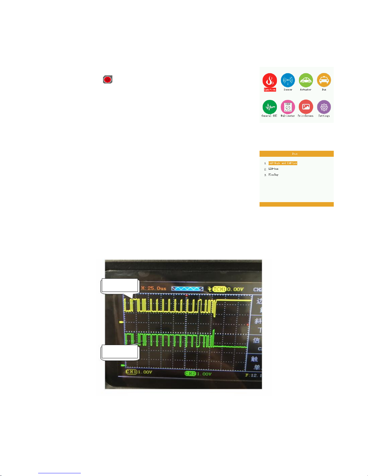
5. Bus
1)CAN-high、CAN-low
①After the oscilloscope installed batteries,long press red power
button“ ”, let it go until you hear the buzzer,at this time
oscilloscope enter the main menu interface,as picture-1
②After entering the main menu interface select “Bus”, then enter
the sub-menu press the up and down keys to select " CAN-high、
CAN-low ",press “OK” button, after confirmation,
entering oscilloscope operation interface, as picture -2
③Connect the two probes to CH1 and CH2, probe set to 1X, then connect
grounding chipotle signal ground or grounding
④Since the “CAN-high、CAN-low” function of oscilloscope has
default settings (CH1,CH2:Probe 1X,time base 25us),simply
connect the probe to the corresponding signal can display
waveform, as picture 14
⑤Press“CH1” and “CH2”,can view the values and configuration
(configuration has default)
⑥Waveform display can be adjusted based on their own through
the vertical volts / division and trigger ways to meet your needs
(Time base, vertical volts / division and other specific operations, please refer to the
operation of general oscilloscope)
Pic-14 CAN-high, CAN-low
Picture-1
Picture-2
CAN-high
CAN-low

23
2) LIN-bus
①Same as CAN-high、CAN-low step 1
②After entering the main menu interface select “Bus”, then enter the sub-menu press
the up and down keys to select " LIN-bus ",press “OK” button, after confirmation,
entering oscilloscope operation interface
③Connect the probe to CH1 and probe set to 1X,then connect grounding clip to the
signal ground or grounding
④Since the “LIN-bus” Function of oscilloscope has default settings (CH1:Probe 1X,
time base 500us),simply connect the probe to the corresponding signal can display
waveform.
⑤Press“CH1” and “CH2”,can view the values and configuration(configuration has
default)
⑥Waveform display can be adjusted based on their own through the vertical volts /
division and trigger ways to meet your needs(Time base, vertical volts / division and
other specific operations, please refer to the operation of general oscilloscope)
3) FlexRay
①Same as CAN-high、CAN-low step 1
②After entering the main menu interface select “Bus”, then enter the sub-menu press
the up and down keys to select " FlexRay ",press “OK” button, after confirmation,
entering oscilloscope operation interface
③Connect the two probes to CH1 and CH2, probe set to 1X, then connect
grounding clip to the signal ground or grounding
④Since the “FlexRay” Function of oscilloscope has default settings (CH1,CH2:Probe
1X,time base 10us),simply connect the probe to the corresponding signal can display
waveform.
⑤Press“CH1” and “CH2”,can view the values and configuration(configuration has
default)
⑥Waveform display can be adjusted based on their own through the vertical volts /
division and trigger ways to meet your needs(Time base, vertical volts / division and
other specific operations, please refer to the operation of general oscilloscope
2.2 Universal Oscilloscope this section features are described
Below:
▲ Menus and control systems
▲ Connector
▲ automatically set
▲ The default setting
▲ Vertical System
▲ Horizontal System
▲ Trigger system
▲ Math system
▲ System Settings
▲ Storage System

24
1. Menus and Control buttons
As shown in the following figure:
ADO102 control button ADO104 control button ADO General Button
All models
CH1、CH2
CH3、CH4
Channel 1, Channel 2 , Channel 3, Channel 4 settings menu
Press the "Return" to return to the previous menu
Press the "Multimeter" mode to enter the multimeter
On / Off
AUTO
Automatically sets the oscilloscope controls, press this key to achieve 20HZ-10MHZ a key
trigger function, Channel 1-Channel 4 can be used
TRIG
Show "Trigger" control menu
HORI
Show "Horizontal" control menu
Continuously acquires waveforms or stops the acquisition. Note: In the stop mode, the
waveform vertical scale and horizontal base can be adjusted within a certain range,
equivalent to extend the signal on the horizontal or vertical direction.
MENU
Function menu interface, the first press of waveform storage interface, the second press to
display settings interface, press three times for the system setup interface
To enlarge, shrink waveform, or move the displayed cursor in oscilloscope mode. Used to
adjust the range, in the multimeter functions.
Can be used to move the waveform display or move the cursor in oscilloscope mode;
select the type of test used in the multimeter functions.

25
OK
Function Confirm
F1、F2、F3、
F4
Corresponding to the selected setting in the Options menu 1,2,3,4
2. Connector
ADO102 ADO104
Figure 2-1 Figure 2-1
Figure 2-1 CH1-CH2: Input connectors for waveform display, the left is CH1,
the right is CH2, "COM" and "VΩ" is used to connect the black and red pen.
Figure 2-2 CH1-CH4: used to display the input waveform connection. "COM"
and "VΩ" is used to connect the black and red pen.
3. Automatically set
ADO has an automatic setting function. According to the input signal,
automatically adjusting the voltage stall, time base, and triggering the best way
to form display.
"AUTO" for automatically setting.
● If there is more than one channel signal, the channel with the lowest
frequency signal as the trigger source.
● Found no signal, connect the channel 1 to a signal, press "AUTO" button. As
shown in figure 2-3:
Figure 2-3
VΩ
COM
CH4 CH3 CH2 CH1
VΩ
COM
CH2 CH1

26
4. Default settings
The oscilloscope is set at the factory for routine operations, which is the default
setting. There oscilloscope main menu "System Settings" in the "factory
restore mode" operation by the arrow keys to select "Factory" and press the
"OK" button to confirm, the instrument off to save and restore the factory
settings, the instrument can be used after restart.
5. Vertical Systems
Channel and its settings
Operation menu of the channel, indicating Table 2-1 below: Table 2-1
Coupling
AC
DC
Blocking the DC component of the input signal.
The ac and dc component of the signal.
Probes
1X
10X
100X
According to the probe attenuation factor to select one of the
values in order to maintain the correct reading of the vertical
deflection factor. There are three types: 1X, 10X, 100X
Display
Open
Close
Open display waveforms
Close display waveforms
Frequenc
y
/
Automatically displays the current input signal frequency
peak-to-
peak value
/
Automatically displays the current waveform peak-to-
peak value.
Duty Cycle
/
automatically displays the current input signal duty
Cycle
/
automatically displays the current input signal cycle
1). Set the channel coupling
To signal applied to the oscilloscope channel, for example, the measured signal is a
square wave signal containing AC component.
●Main menu, select "Universal oscilloscope" press "OK" button to enter the oscilloscope
screen. Press "CH1" → "Coupling DC", press “F3”set to DC coupling. DC and AC
components of the input signal to pass through.
As Figure 2-4
● Press "CH1" → "Coupling AC", press “F3” set to AC coupling. DC component of the
input signal is blocked. As Figure 2-5
● Press "CH1" → "Inverse" and press the SELECT function key "F4" to anti opposite way.
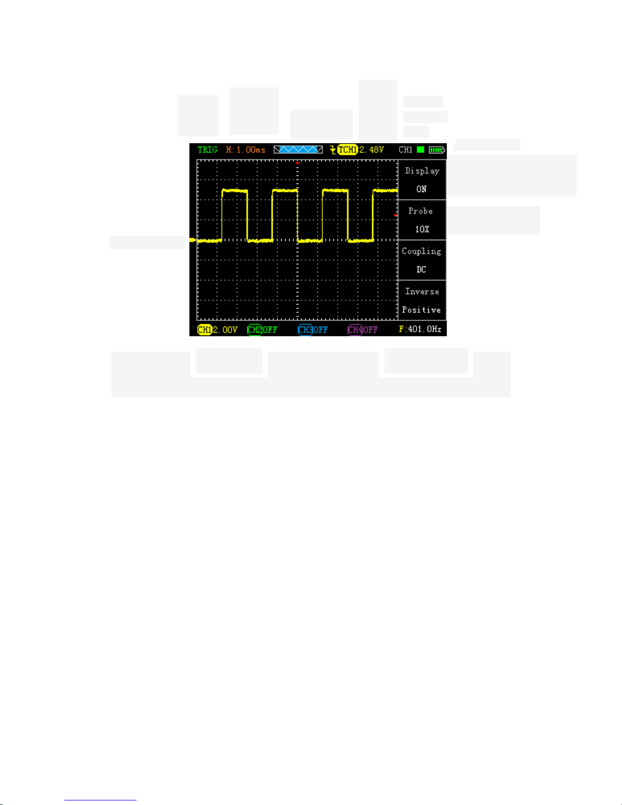
Inverting the signal display. Figure 2-6
Figure 2-4 Figure 2-5 Figure 2-6
2).Probe scale setting

27
To cope with the attenuation factor of the probe set, User need adjust the probe
attenuation scale factor in channel operation menu. If the probe attenuation coefficient
ratio is 10:1, Oscilloscope input channel ratio should be set to 10X, and so on. To avoid
the display of information and measurement data errors occur. Take the CH1 for example:
● Press "CH1" → "F2" to set the probe ratio for 10X.
3).Vertical volts/division adjustment setting
When adjusting the vertical volts/div, the range is 100mV/div-50V/div (probe 10X),
Stepping way to 1-2.5-5, or 10mV/div-5V/div (probe 1X), 1V/div-500V/div (probe 100X).
Take the CH1 for example:
● If you set the vertical direction 2.00V/div,press"CH1"→ " "or " " to adjust the
vertical volts / division, press " " or " "to move up and down the entire waveform. As
Figure 2-7
● If you set the vertical direction 1.00V/div, the steps in the above example. As Figure 2-8
Figure 2-7 Figure 2-8
6. Horizontal Systems
Use the control buttons to change the level of the horizontal scale (time base), trigger
horizontal position (trigger position) in memory. Changing the horizontal scale causes the
waveform relative to the screen center expansion or contraction, Change the horizontal
position relative to the change point of the waveform trigger position.
Table 2-2 Main Menu of horizontal time base
Master
time
base
Horizontal main time base setting is used to display the waveform
Master
time
base
cursor
state
Display
Set cursor display or not display
Source
Select cursor measurement signal source (CH1-CH4)
Type
There are two types of time and voltage
Cursor
display
Cursor1
Cursor 2
Time base offset relative to the main vector

28
● Horizontal scale: Adjust the main group; press the "HORI" button, Press" "or" " to
change the scale of the level. To zoom in or out waveform. If you want to stop waveform
acquisition, press the "RUN" key can be realized. As Figure 2-9, Figure 2-10
Figure 2-9 Figure 2-10
● Horizontal Position: adjust the horizontal position of the waveform (trigger position
relative to the center of the screen).Press the "HORI" button, Through " " or " "to
move the waveform left or right. The key resolution varies according to time base. Press
"AUTO" key can make the horizontal position return to zero.
●Cursor measurement: adjust the measurement, press the "time base" keys, press
"F2-F4" to select the corresponding function (display, source, type), and then press the
"time base" on the cursor key to enter the display interface, and then " " " " or " ",
" " key to adjust the cursor position.
7. Trigger system
The trigger determines when the oscilloscope starts to acquire data and display
waveforms. Once the trigger is set up correctly, it can convert the unstable display into
meaningful waveforms. Trigger Control menu button" TRIG".
● Trigger Control
Trigger: The oscilloscope trigger mode is edge triggered.
● Edge Trigger: When the edge of the trigger signal reaches a given level,
Trigger occurs. Edge trigger is triggered on the input signal edge trigger threshold. When
"Edge”, that is input at the rising edge, falling edge triggered.
Table 2-3 Edge trigger function menu
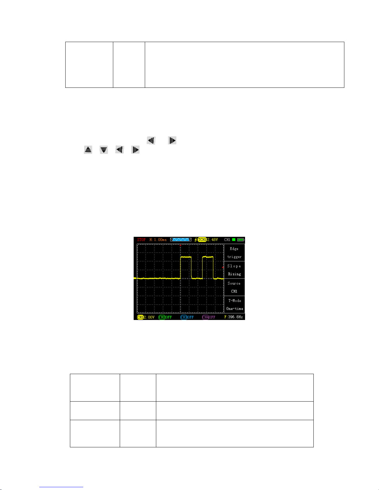
Source
oscillosc
ope
Set CH1 as trigger source. (CH2-CH4 empathy)
Slope
UP
DOWN
Select the trigger signal to trigger on the rising edge
Select the trigger signal to trigger on the falling edge
Incremental
Cursor 2 - Cursor 1
29
Trigger mode
Auto
Normal
Single
Set in the absence of detectable also can collect waveform trigger
conditions Set only a triggering
condition is satisfied only waveform
Set capture a waveform when a trigger is detected, then stop
Instructions:
Set the source:
1).Main menu, select "Universal oscilloscope" press "OK" button to enter the oscilloscope
screen. Press the "TRIG" button to display the trigger menu, according to the signal input,
press the "F3" key to select CH1-CH4.
2).Press "CH1", then press" "or" "adjusts channel 1 mark. Press the "TRIG", then
press" "" "or" "" "adjust the trigger flag arrow, According trigger flag each cell
voltage value represents the relative position and the current channel a flag vertically to
set the trigger level size.
Set slope:
3).Press the "F2" key to select slope "up" or "down."
Set trigger mode:
4).Press the "F4" key to select "Auto", "normal" or "single."
Auto: Set in the absence of detectable also can collect waveform trigger conditions
Normal: Set only a triggering condition is satisfied only waveform Single: Set capture a
waveform when a trigger is detected, then stop As Figure 2-11
Figure 2-11
8. Math System
Math function is to display CH1, CH2, CH3, CH4 two two-channel waveform additions,
subtraction functions
Table 2-4 Math Functions
Menu
Settings
Comments
Setting
Description
Arithmetic
Functions
/
Source A
Settings
Source
CH1-CH4
Set CH1, CH2, CH3, CH4 as source B

30
Source B
Settings
Source
CH1-CH4
Set CH1, CH2, CH3, CH4 as source B
Operation
A+B、A-B
or NULL
Be A + B or A-B operation according to the source A,
Source B is set above
▲Press the "operation" button then press the "F4" select operation mode and turn on the
display.
9. System Setup
Table 2-5 System Functions menu
Menu
Settings
Comments
Setting
Description
Sound
Sound
Set sound to "ON" or "OFF"
Display
brightness
Brightness
Can be set from 1-5
Language
/
Chinese or English
Color
System
theme
four styles to choose "default", "style one"、" style
two", " style three "
Location
History
On / Off
Minutes of the last open position
Version
Information
/
Check the software version of the oscilloscope
Restore
Factory
/
Reset
System Settings
1) Sound settings: the main menu, select "System Settings" button, press the "OK" button
to enter the settings interface, via the arrow keys to select "Sound" press "OK" button,
enter the change, left and right keys to select On or Off and then press "OK "button to
confirm.
2) brightness setting: the main menu, select "System Settings" button, press the "OK"
button to enter the settings interface, via the arrow keys to select "Brightness" press "OK"
button to enter modify, add brightness left minus right then press "OK" key to confirm; the
machine can be set brightness 1-5.
3) language setting: the main menu, select "System Settings" button, press the "OK"
button to enter the settings interface, via the arrow keys to select "Language" press "OK"
button, enter the change, left and right keys to select the language and then press the
"OK" button confirm; the unit provided in both Chinese and English display interface.
4) Color settings: language setting: the main menu, select "System Settings" button, press
the "OK" button to enter the settings interface, via the arrow keys to select "System risers"

31
press "OK" button, enter the change, up and down keys to select a topic style and then
press "OK" button to confirm, the unit provides four display style theme.
5) to restore the factory: the main menu, select "System Settings" button, press the "OK"
button to enter the settings interface, via the arrow keys to select "Factory" press "OK"
button, enter the change, left and right keys to select OK or Cancel, then press "OK"
button to confirm the WTR.
10. The storage system
ADO Series can store two reference waveforms, 20 groups of shots (depending on
memory size oscilloscope decision) to the oscilloscope internal memory.
ADO Series provides USB interface, you can save waveform memory shots to the U disk,
the common image BMP image file can be opened by computer software. In addition, two
sets of waveform parameters are stored and can be produced by "reference waveform"
were transferred out, displayed on the screen.
To save a reference waveform:
1) Main menu, select "Universal oscilloscope" (Automotive Oscilloscope select the
corresponding module), press the "OK" key to enter the user interface
2) Press the "time base", "trigger" or "operator" to any of these options, press "F1" to enter
the reference waveform
3) press "F2" to select the source, then press the "F2" Reference Waveform (each source
can save two set of reference waveform Ref1, Ref2), press the "F4" key to save the
reference waveform and displayed by pressing the "F2 "button selected as the reference"
NULL "to close the reference waveform
Store pictures steps:
Any Screenshots:
1) Oscilloscope and automotive modules interface, long press "F2" operating status
(battery indicator on the left side) will be blinking green to being shot, wait a few seconds,
the name of the successful bomb box prompts screenshots and screenshots will appear.
2) Multimeter screenshot will be prompted "is being shot”, will appear successful bomb
box prompts screenshot success.
3) Other interfaces will be prompted being shot, after a successful theme screenshot
bomb box prompt success.
Note: The screenshot function can save 20 or so maps, depending on memory size of the
decision, if prompted screenshot fails, re-theme look, or not, then you see the next
memory to delete a few pictures.
View storage oscilloscope image method:
1) First off the oscilloscope, and then use the data cable to connect the oscilloscope and
the computer, and then press the "F3" key and the "on / off" button until the screen to let
go when the light; this time, the computer will prompt U disk insert, open U disk to see the
pictures taken. After the operation, you must first click Exit U disk mode on the computer,
then disconnect the cable, press the power button to reboot to use it again.
2) to enter the main menu, select the screenshot function, go to theme preview feature to
view screenshots. After the arrow keys can be selected theme, select press "OK" button to
view, press any key to return to the list of shots, "F3" key means to delete the currently
selected theme, "F4" button to remove all screenshots.
32
Waring: Please don’t use any measure function when the USB cable is
connecting with other devices, or this Instrument Will Be Damaged.
2.3 Multimeter function and operation
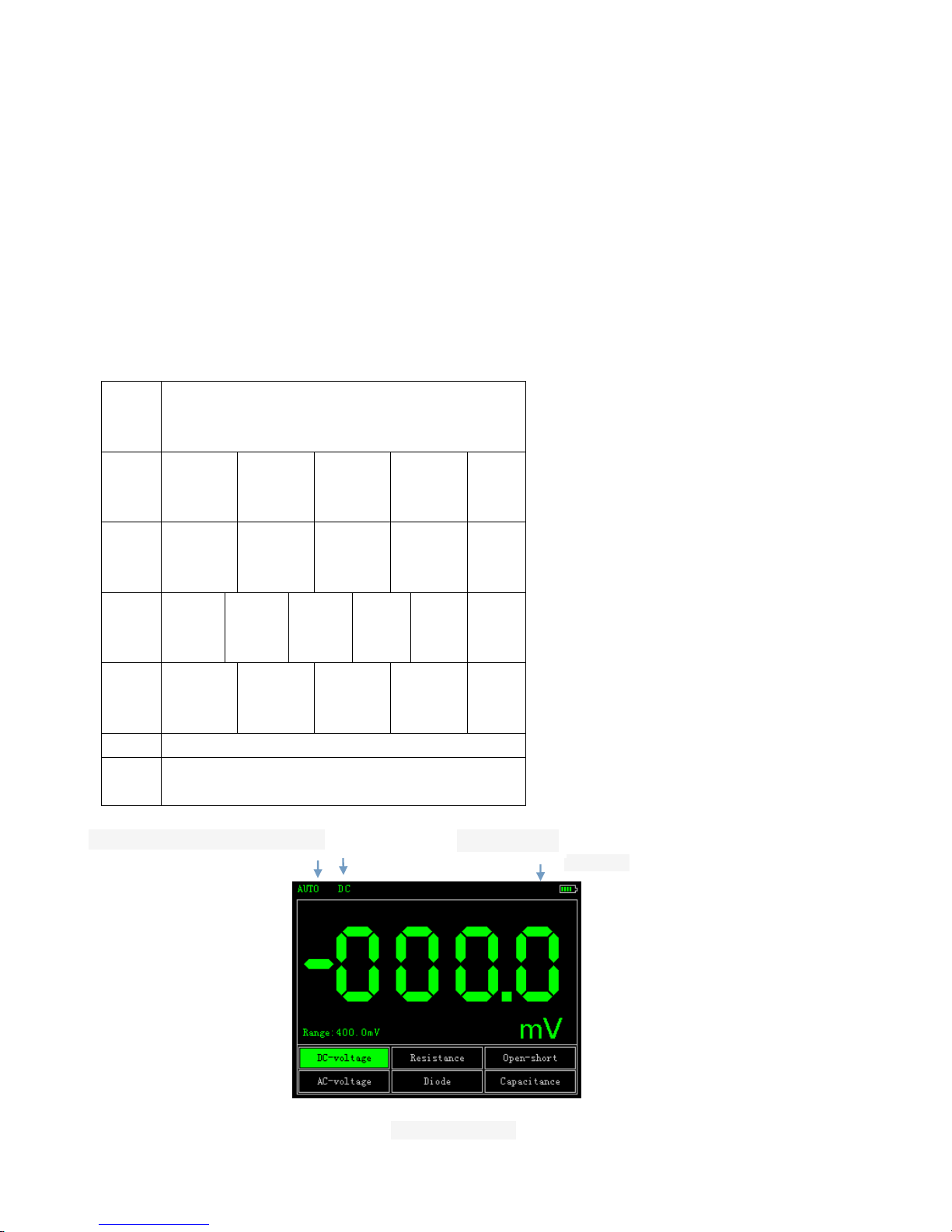
This device can be used as a Multimeter or OSC; can be used for measuring DC and AC
voltage, resistance, capacitance, diode, buzzer-off. This device uses TFT full color display,
and has a range display, polarity display, overload display, battery power display.
Meas
ure
Type
Range
DC
Voltag
e
400.0m
V
4.000V
40.00V
400.0V
1000
V
AC
Voltag
e
400.0m
V
4.000V
40.00V
400.0V
750V
Resist
ance
400.0
Ω
4.000
KΩ
40.00
KΩ
400.0
KΩ
4.000
MΩ
40.00
MΩ
Capa
citanc
e
51.2nF
512.0nF
5.120uF
51.20uF
100u
F
Diode
0V-1.5V
Buzze
r-off
Below 60Ω ,buzzer alarm
DC or AC
Electricity
Running state
Display manually or automatically
Meter Interface
33
Measure Method:
Table2-7 Multimeter Operation Key Function
Key
Description
Multimeter
Press this key to enter Multimeter Mode.
Press “ ” or “ ” to select Mesure Type
Press “ ” or “ ” to tune the Range
Multimeter’s RUN/HOLD key.
Note 1: Multimeter’s default range is "Auto" position, for manually setting the
range, first predicted your Measurements..
Note 2: Display screen show flashing “ ”means Multimeter is
running;” MANU” means manually set the range.
⒈ DC and AC Voltage measuring
① The Black Pen connect to the COM interface on the top of the device(the
black interface),and the Red Pen connect to VΩ interface(the red
interface)
② Press “ON/OFF” key until the system is started, then press “Multimeter”
key to switch to Multimeter Function.
③ Press “ ” or “ ” to select “DC voltage” or “AC Voltage” measuring.”DC
Voltage” has a Shortcut,”F1”.
④ Connect the test pen to the measured voltage, the device will read the
value and show on the screen (it can also read negative value.).AC Voltage
has no polarity. This device’s default Range is “Auto”, you can press “ ” or
“ ” to change the Range.
⒉ Resistance measuring
① Press “ ” or “ ” to select Resistance mesuare.it has a shortcut,”F2”.
② Put the pen on the two side of the resistor, device can read it’s value.
Maybe you should set the Range manually.
⒊ Capacitance measuring
① Press “ ” or “ ” to select Capacitance mesuare.
② put the pen on the two side of the capacitance, device can read it’s value.
Note: Capacitance measuring can’t set Range.
⒋ Diode and Buzzer-off measuring
① Press “ ” or “ ” key to select “Diode” or “Buzzer-off” measuring. Buzzer-off
measuring has a shortcut ,”F3”.
② Put the pen on the two side of the Diode or the line, device can read it’s value.(The
value when measuring diode, it’s diode Conduction voltage drop)
③ When mesuareing resistance is below 60Ω, buzzer alams.
Attention:
a. The device has forward and reverse voltae, when the diode connected reversed, the
value is negative.

34
b.Diode and Buzzer-off mearusing only have “Auto” Range.
c.When measuring,must keep “Sound” On, or the Buzzer can’t alarm.
Ways to setup:
1、press the "back" button, until the main menu through the arrow keys to select
the "Settings", click "OK" button to enter the setting
2、using the arrow keys select "sound", click "OK" button appears bomb box,
through the left and right button to select the open and click "OK" button to confirm
5、 Data Hold Function
"Run / Stop" button is pressed on the instrument, the data will remain being displayed on
the display even if the input signal changes, or eliminate, the value is not changed
Waring 1: When using Multimeter, the OSC dector must not connect to
GROUND.
Waring 2: Please select the appropriate Range before measure object.
Waring 3: When the USB cable is connect to other devices, must not
measur, or the device will be damaged.
Chapter3 Application Examples
3.1 Singal measure
Measure an unknown signalman show it’s value immediately.
● If you want show the value immediately ,please do as fllows:
① Enter the "Universal oscilloscope”. Set the probe menu attenuation coefficient as 10X,
and switch the probe to 10X.
② Connect the CH1 probe to the test point.
③ Press “AUTO” key.
The OSC will automatically set the optimum waveform display. Then you can adjust the
Vertical or Horizontal scale, until the waveform meets your requirements.
● Automatic measure signal’s voltage and time parameter.
The OSC can automatic measure most signals. To measure the frequency and
peak-peak,follw the steps:
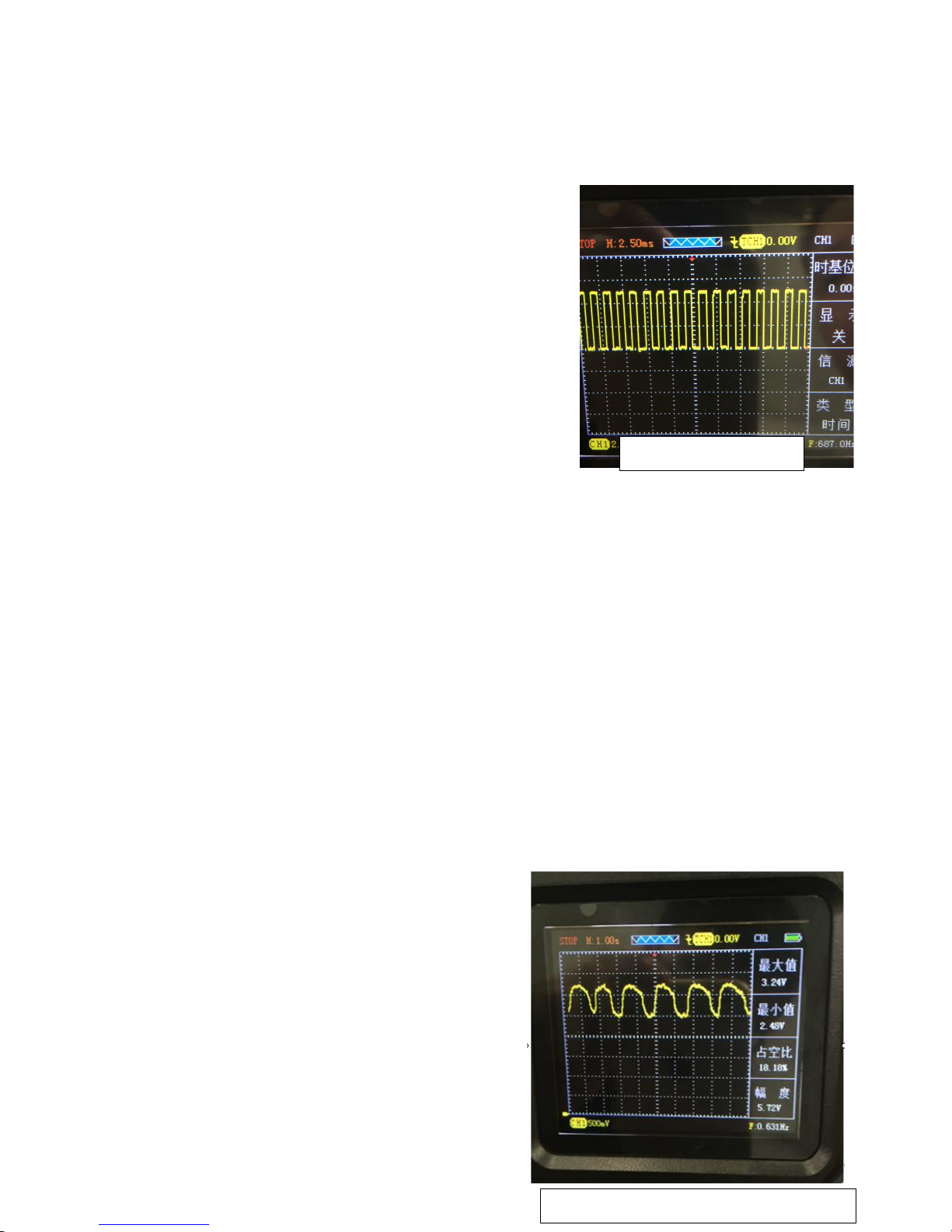
① Enter the "Universal oscilloscope”. Press “AUTO” key, show current waveforms.
②Press "CH1" button to turn pages can be observed maximum, minimum, duty cycle,
amplitude. (CH2-CH4 similar operations)
In this case, the signal parameter measurements are shown in
F1-F4 corresponding to the location, you can display the
signal parameter values by pressing the corresponding F1-F4
function key to select. Figure 3-1
3.2 Cursor measure
This OSC can automatic measure a variety of waveform
parameters. All measurement parameters can be measured
by the cursor.Use the cursor, can measure the waveform parameters quickly. Figure 3-1
Measuring the peak voltage of square wave signal.
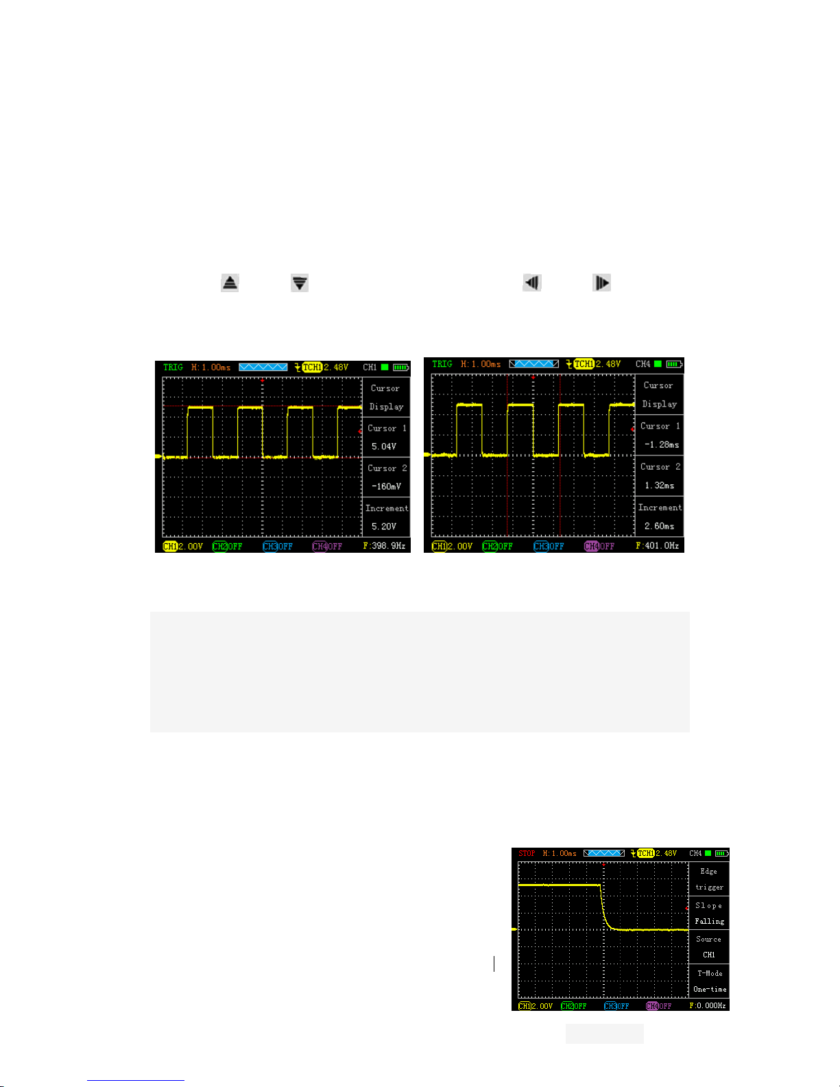
35
Take the CH1 for example. if you want to measure the peak voltage of a square wave
signal, do as follows:
① Press “HORI” key to enter the main base cursor
state setting.
②Press “F2” key to set the cursor “ON”; Press “F2” key to set the source as “CH1-CH4”;
press “F4” key to set the type of the cursor “Voltage”.
③Press “HORI” key again to see location of cursor 1 and cursor 2(relative to the
intermediate zero volate reference level) and increment (V_cursor2-V_cursor1)
④ Press “ ” and “ ” to tune the position of cursor 2,“ ” and “ ” to tune the
position of cursor 1;and there position and increment will updating on the screen in
Real-time. See Pic 3-2 and Pic 3-3.
Figure 3-2 Figure3-3
3.3 Capture the Single Signal
Digital storage oscilloscope advantages and features that could easily capture the
periodic signal pulses, glitches, etc. To capture a single signal, this signal first needs to
have some prior knowledge, in order to set the trigger level along. If the case of a signal of
uncertainty, you can automatically trigger mode or normal first observation to determine
the trigger level along.
Steps are as follows:
1、As aforementioned, set the attenuation coefficient of probe and CH1 channel to 10X.
2、Trigger settings:
① Press "CH1” key → press "F3" key to set the coupling to "DC."
② Press the "TRIG" button to display the edge trigger menu settings.
In this menu, press “F1” key to set the edge type “slope down”,press “F2” key to set
the source “CH1”,press “F3” key to set the trigger mode to
“single”.
④ Press “RUN” key, the left corner of the display screen
will displays “SIGL”,waiting for the signal meets the trigger
condition occurs. If the trigger signal reaches the ertain
conditions, it will displays on the screen. With this feature
Figure 3-4

36
you can easily capture the event accidental, such as a suddenly low
voltage:press”RUN” key to start the wait when there is a low level occurs, the devices
will automatically trigger and the trigger waveform record before and after a period of time
off.”HORI” key can change the horizontal position of the trigger position, and then you can
get different lengths, which can easily observe the waveform. See Figure 3-4
3.4 Use Multimeter to Measure DC Voltage
● Use “AUTO” measure DC Voltage.
① Press “AVΩ”key, enter Multimeter mode,
Auto range default.
② Press “ ” or “ ” to select “DC Voltage”
③ Put the pen on the test point, and it will read The value.
See Figure 3-5.
● Set the Voltage Range manually.
① Press “ ” or “ ” to select “DC”
② Press “ ” or “ ” to adjust the range.
See figure 3-6.
Chapter 4 System Tips and Troubleshooting
4.1 Prompting Message
Trigger level limit:
Horizontal position limit:
Voltage range limit:
USB storage device is connected successfully:
4.2 Troubleshooting
1. If you press the " " button oscilloscope screen remains dark, no display,
follow these steps:
(1) Open the instrument battery cover, check whether the power supply or battery power
leakage, flatulence, etc.
(2) After the inspection is completed, restart the instrument.
(3) If you still can not properly use the product, please contact us.
2. After signal acquisition, signal waveform screen does not appear, please
Figure 3-6
Figure 3-5

37
follow these steps:
(1) Check whether the probes are correctly connected to the signal line connection.
(2) Check whether the signal cable is properly connected to the BNC.
(3) Check whether the probe is properly connected with the analytes.
(4) Check whether the analyte signal is generated.
(5) Re-acquire the signal again.
3. Measured voltage amplitude value is 10 times greater than the actual value,
or 10 times smaller:
Check whether the channel attenuation factor of the probe matches the actual
attenuation ratio.
4. There waveform display, but not stable:
Check the trigger source trigger menu settings are consistent with the actual
signal input channels.
5. Press "RUN" button without any display:
Trigger checks whether the trigger menu in the "normal" or "Single" and the
trigger level has been exceeded if the signal range. If it is, the trigger level is
centered, or set the trigger mode to "AUTO" file.
6.Stepped waveform display:
This phenomenon is normal. When the base level is too low may stall,
increasing the level of the base when the horizontal resolution can be
increased to improve the display.
Chapter 5 service and support
5.1 Warranty Description
We guarantee the production and sale of its products, the date of shipment from
authorized dealers within a year, does not appear in material and workmanship defects.
As specified in the detailed product warranty proved defective, we will provide repair or
replacement service.
In addition to this summary, or use the warranty provision of the warranty, we do not make
any other warranties, express or implied. The Company's indirect, special or damage
arising there from shall not be liable.
Appendix A: Technical Specifications
Unless otherwise noted, all technical specifications are used for attenuation switch setting
10X probes and these series oscilloscopes.
To verify that the oscilloscope meets specifications, the oscilloscope must meet the
following conditions:
●The oscilloscope must be more than thirty minutes of continuous operation within the

38
specified operating temperature.
●If the operating temperature changes by more than 5 degrees, will have to be corrected,
unless labeled "typical" outside the specifications, all specifications are guaranteed.
●Oscilloscope must be within the factory calibration interval.
Technical Specifications
import
Input coupling
AC、DC
Input impedance
1MΩ 25pF
The maximum
input voltage
40V (probe X1); 400V (probe X10) can be measured 220V voltage;
(probe X100) 2000V voltage can be measured
Probe
attenuation
1X、10X
Set the probe
attenuation
factor
1X、10X、100X
Signal
acquisition
system
Sampling
Method
Real-time sampling, random sampling
Memory depth
4K
Acquisition
Mode
Sample, Peak Detect
Vertical System
Vertical
Sensitivity
10mV-5V (Probe 1X) 100mV-50V (probe 10X) (1,2.5,5 step)
Vertical accuracy
+/-3%
Vertical
resolution
8bit
Bandwidth
10MHz
Horizontal
Systems
Real-time
sampling rate
100 MSa/s
Horizontal scan
range
25nS/div-5S/div
Trigger System
Mode
Auto, Normal and Single
Type
Rising edge trigger, falling edge trigger
Automatic
detection
Support (20Hz-10MHz)
Measurement
System

39
Cursor
measurements
Support time and voltage cursors
Measurements
Manual
Measure
Peak and frequency
Equipment
Screen
3.2-inch, 16-bit true color, TFT, 320 * 240
Battery
3000 + mA lithium battery (single cell about four hours of
continuous work)
Size
115 * 180 * 35 (mm)
Appendix B: ADO 102/ADO 104 oscilloscope accessories
ADO 102 oscilloscope: ADO 104 oscilloscope:
- User manual (CD) - User manual (CD)
- Certificate - Certificate
- A dedicated high-voltage - Two dedicated
ignition probe (Found 1: 3000) high-voltage ignition probe (1: 3000)
- 1: 1/10: 1 probe two - 1: 1/10: 1 probe four
- Multimeter table pen one pair - Multimeter table pen one pair
- Four broken wire needle - Six broken wire needle
- Lithium battery × 2 - lithium batteries × 2
- Battery Charger - Battery Charger
- Portable Kit - Portable Kit
- USB cable one - USB cable one
Appendix C: routine maintenance and cleaning
Routine maintenance
Do not store or leave the instrument in where the LCD display will be exposed to direct
sunlight for a long time.
Do not allow sprays, liquids and solvents touches on the instrument or probe, to avoid
damage to the instrument and probe.
Please charge the battery in the battery is finished using the situation.
Clean
Regularly inspect the instrument and probe according to operating conditions.
Please follow the steps below to clean the outer surface of the instrument:
1.Use external dust soft cloth to wipe the instrument and probe. When cleaning the LCD
screen, be careful not to scratch the clear plastic protective screen.

40
2.Use a damp but not dripping, soft cloth to wipe the instrument, please remove the
battery before wiping. Use a mild detergent and water to scrub. Do not use any corrosive
chemicals, to avoid damage to the instrument and probe.
WARNING: Before reinstalling the battery, make sure the instrument is completely
dry to avoid water damage to equipment caused by electrical short circuit.
 Loading...