

Jinan USR IOT Technology USR-TCP232-24, USR-TCP232-2, USR-TCP232-S, USR-TCP232-D, USR-TCP232-200 Instructions Manual
...Page 1

S erial to Ethernet module USR-TCP232-T24 series http://en.usr.cn
S
erial
S
erial
S
S erial
erial to
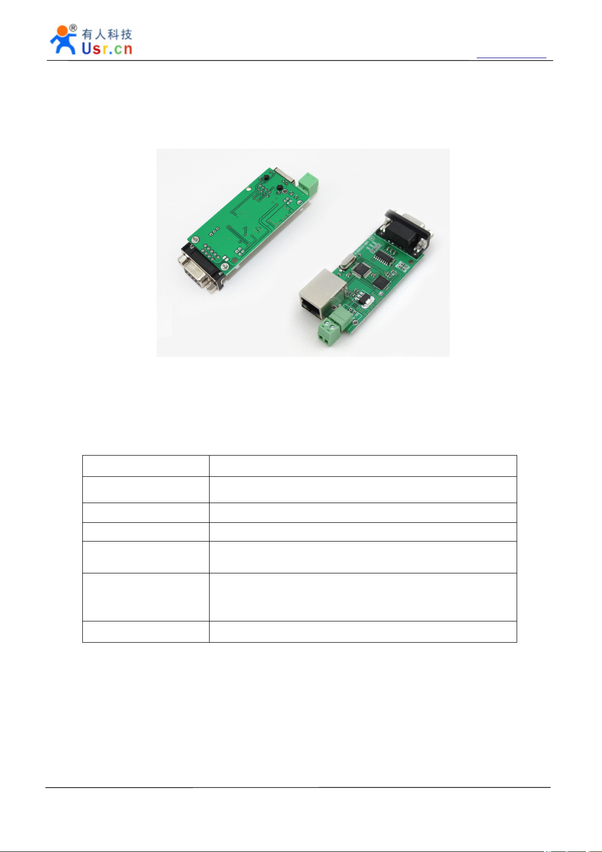
The USR- TCP232-T24 series is data transparent transmission e quipment for convert TCP or UDP
socket data to RS232 or RS485 or RS422 , easy to use, small size, low power, powered by ARM processors ,
high speed , high Stability.
Our concept: simple functions, stable performance, reasonable price.
Jinan USR IOT Technology Limited works on LAN and WAN and wireless for MCU to Ethernet Solutions,
Ethernet, WIFI, GPRS, Zigbee and Wireless modules, we can supply custom design for those usage, look ing
forward to cooperat e with you.
to
Ethernet
to
Ethernet
to Ethernet
Ethernet module
(USR-TCP232-T, USR-TCP232-2)
(USR-TCP232-S, USR-TCP232-D)
(USR-TCP232-24, USR-TCP232-200)
(USR-TCP232-300, USR-TCP232-442)
module
module
module
File version: V 3.0
Jinan USR IOT Technology Limited Page 1 of 53 tec@usr.cn
Page 2

S erial to Ethernet module USR-TCP232-T24 series http://en.usr.cn
Content
Content
Content
Content
Serial to Ethernet module ............................................................................................................................................... 1
1 . Product introduce ............................................................................................................................................... 4
1.1 Introduction ................................................................................................................................................. 4
1.2 Function Features ...................................................................................................................................... 4
1.3 Product Features ....................................................................................................................................... 4
1.4 Applications Area ....................................................................................................................................... 5
1.5 Order information ....................................................................................................................................... 5
2. Hardware Description .......................................................................................................................................... 6
2.1 USR-TCP232-S ......................................................................................................................................... 6
2.1.1 Technical Specifications ................................................................................................................ 6
2 .1.2 Hardware Description .................................................................................................................... 7
2.1.21 Pin Description ..................................................................................................................... 7
2.1.22 Mechanical Dimensions ...................................................................................................... 8
2.1.23 Connection Diagram ............................................................................................................ 9
2.2 USR-TCP232-T ....................................................................................................................................... 10
2.2.1 Technical Specifications .............................................................................................................. 10
2.2.2 Hardware Description ..................................................................................................................
2.2.21 Pin description ....................................................................................................................
2.2.22 LED status ........................................................................................................................... 12
2.2.23 Mechanical Dimensions .................................................................................................... 12
2.2.24 Connection Diagram .......................................................................................................... 12
2.3 USR-TCP232-D ....................................................................................................................................... 13
2.3.1 Technical Specifications .............................................................................................................. 13
2. 3 .2 Hardware Description .................................................................................................................. 14
2.3 .21 Pin Description ................................................................................................................... 14
2.3.22 LED status ........................................................................................................................... 14
2.3.23 Mechanical Dimensions .................................................................................................... 15
2.4 USR-TCP232-2 ........................................................................................................................................ 16
2.4.1 Technical Specifications .............................................................................................................. 16
2.4. 2 Hardware Description .................................................................................................................. 17
2.4.21 Pin Description ................................................................................................................... 17
2.4.22 Interface Description .......................................................................................................... 17
2.4.23 Jumper usage Mechanical Dimensions ....................................................................... 18
2.5 USR-TCP232-200 ................................................................................................................................... 19
2.5.1 Technical Specifications .............................................................................................................. 19
2. 5.2 Hardware Description .................................................................................................................. 20
2.5.21 Pin Description ................................................................................................................... 20
2.5.22 Interface Description .......................................................................................................... 20
2.5.23 Jumper usage Mechanical Dimensions ....................................................................... 21
2.6 USR-TCP232-24 ..................................................................................................................................... 22
2.6.1 Technical Specifications .............................................................................................................. 22
2.6.2 Hardware Description .................................................................................................................. 23
11
11
Jinan USR IOT Technology Limited Page 2 of 53 tec@usr.cn
Page 3

S erial to Ethernet module USR-TCP232-T24 series http://en.usr.cn
2.6.21 LED status ........................................................................................................................... 23
2.6.22 Interface Description .......................................................................................................... 23
2.6.23 Jumper usage Mechanical Dimensions ....................................................................... 25
2.7 USR-TCP232-300 ................................................................................................................................... 26
2.8 USR-TCP232-442 ................................................................................................................................... 27
2.8.1 Technical Specifications .............................................................................................................. 27
2.8.2 Hardware Description .................................................................................................................. 28
2.8.21 LED status ........................................................................................................................... 28
2.8.22 Interface Description .......................................................................................................... 28
2.8.23 Terminal functional specifications .................................................................................... 29
2.8 .24 Jumper usage Mechanical Dimensions ....................................................................... 29
3 . Work Mode ......................................................................................................................................................... 30
3.1 Block diagram .......................................................................................................................................... 30
3.2 TCP Client Mode ..................................................................................................................................... 30
3.3 UDP mode ................................................................................................................................................ 30
3 .4 UDP server Mode .................................................................................................................................... 31
3 .5 TCP server Mode .................................................................................................................................... 32
3.6 Special functions ..................................................................................................................................... 33
3.61 RS485 ............................................................................................................................................. 33
3.62 Link .................................................................................................................................................. 33
3.63 Reset ............................................................................................................................................... 33
3.64 ID ..................................................................................................................................................... 33
3.65 Index ................................................................................................................................................ 36
3.66 RFC2217 ........................................................................................................................................ 36
4. Configure ............................................................................................................................................................ 39
4.1 Configure command format ................................................................................................................... 39
4.2 Configure through RS232 ...................................................................................................................... 40
4.4 USR-TCP232-SETUP ............................................................................................................................. 41
5. Test Methods ...................................................................................................................................................... 41
5.1 General
Test
............................................................................................................................................. 41
5.2 Virtual COM .............................................................................................................................................. 45
6. Apps ..................................................................................................................................................................... 49
6.1 COM<->TCP/UDP<->server .................................................................................................................. 49
6.2 Virtual COM .............................................................................................................................................. 49
6.3 COM <-> TCP/UDP <-> COM ............................................................................................................... 50
6.4 many COM <-> UDP server <-> COM ................................................................................................. 50
6.5 COM<-> TCP/UDP<->proxy server <->TCP/UDP<->COM .............................................................. 51
6.6 COM <-> TCP/UDP <-> server ............................................................................................................. 52
7. Contact us ........................................................................................................................................................... 53
8. Doc History ......................................................................................................................................................... 53
Jinan USR IOT Technology Limited Page 3 of 53 tec@usr.cn
Page 4

S erial to Ethernet module USR-TCP232-T24 series http://en.usr.cn
1
Product
.
1
Product
.
1
1
Product
Product introduce
.
.
1.1
Introduction
1.1
Introduction
1.1
1.1 Introduction
Introduction
USR-TCP232-T24 series is used to TCP network packet or UDP packet with the microcontroller /
RS232/RS485/RS422 interface data transparent transmission equipment. The product is equipped with ARM
processors, high speed, high stability. Module class of compact size, low power consumption; server refined
aluminum metal shell, compression, anti-drop, anti-interference performance .
USR-TCP232-T24 4 series is more functional embedded Ethernet serial port data conversion products, it
has built-in TCP/IP protocol stack, the user can use it easily to complete embedded devices network function,
save manpower material resources and development time, make our products faster to market, enhance
competitiveness.
There is 10/100M auto detected RJ45 interface, serial communication baud rate up to 230.4Kbps, can
work at TCP Server, TCP Client, UDP and UDP server mode, setup easily via series or RJ45.
1.2
Function
1.2
Function
1.2
1.2 Function
Function Features
introduce
introduce
introduce
Features
Features
Features
100M high speed Ethernet card, 10/100M auto detect interface;
�
support AUTO MDI/MDIX, Can use a crossover cable or parallel cable connection;
�
RS232 bound rate can set up from 300 to 256000 ;
�
RS485 bound rate can set up from 300 to 115200 ;
�
Work mode TCP Server, TCP Client, UDP , UDP Server ;
�
Working model related parameters can be set via a serial port or network ;
�
3.3 V and 5 V TTL level compatible (module products );
�
Virtual serial port supported;
�
Unique heartbeat package mechanism to ensure that the connection is reliable, put an end to connect
�
feign death ;
across the gateway, across switches, routers ;
�
Can work in LAN, also can work on the Internet (external network) ;
�
Transmission distance: RS232 - 15 meters, RS485 - 1000 meters, cable 200 meters (after the switches
�
together through the Internet, no distance limit) .
1.3
Product
1.3
Product
1.3
1.3 Product
Product Features
� 32 bits ARM CPU inside;
� LAN : 10/100Mbps; protect: Built-2KV isolated electromagnetic;
� serial port baud rate: from 2400 to 256 KBPS can be set up, and up to 3 MBPS ;
� network protocol: ETHERNET ARP IP UDP TCP ICMP;
� Software tool: configuration software, TCP/UDP test soft, RS232 debug soft ;
� Configuration method: RS232 or via Ethernet, free software available ;
� Operating temperature: -25~75 ° C ;
� Save the environment: -40~85 ° C, 5~95%RH.
Features
Features
Features
Jinan USR IOT Technology Limited Page 4 of 53 tec@usr.cn
Page 5

S erial to Ethernet module USR-TCP232-T24 series http://en.usr.cn
1.4
Applications
1.4
Applications
1.4
1.4 Applications
Applications Area
Serial device server module for connecting serial industrial automation equipment such as PLC, sensors,
meters, motors, drives, bar code readers and displays and design. Serial server module is widely used in
attendance, access control systems, Canteen machines, POS systems, building control, fire control, the
banking system, engine room monitoring, UPS monitoring, power, oil, environmental monitoring, industrial
applications and other areas all need to serial devices Data network management where you can use a serial
device server solution.
1.5
Order
1.5
Order
1.5
1.5 Order
Order information
Model
Model
Model
Model number
information
information
information
number
number
number
Area
Area
Area
Powe
Powe
Powe
Powe r
DC
DC
DC
DC
r
supply
r
supply
r supply
supply
I
nterface
I
nterface
I
I nterface
nterface
Network
Network
Network
Network port
10/100Mbps
10/100Mbps
10/100Mbps
10/100Mbps
port
port
port
Package
Package
Package
Package Type
(
Module
(
Module
(
( Module
Module products
Type
Type
Type
products
products
products )
)
)
)
USR-TCP232- S 3.3V TTL
USR-TCP232-T 5V/3.3V TTL
USR-TCP232-D 5V/3.3V TTL
USR-TCP232-2
USR-TCP232-200
USR-TCP232- 2 4
USR-TCP232-300
USR-TCP232-442
Model Description: USR is our brand, TCP232 that TCPIP to serial module product, 2/4/T that serial-side
level in the form.
B USB/5V
terminal
5 V power
adapter/terminal
5 V power
adapter/terminal
5 V power
adapter/terminal
5 V power
adapter/terminal
RS232
RS232
RS232/R
S485
RS232/R
S485
RS485/R
S422
PHY chip network
interface
T
ake 2kv magnetic
isolation RJ45
W ith 1.5KV PHY signal
of electromagnetic
separation
Take 2 kv magnetic
isolation RJ45
Take 2 kv magnetic
isolation RJ45
Take 2 kv magnetic
isolation RJ45
Take 2 kv magnetic
isolation RJ45
Take 2 kv magnetic
isolation RJ45
Stamp Hole
Package
Pin package (DIP
package)
Pin package
(DIP package)
Jinan USR IOT Technology Limited Page 5 of 53 tec@usr.cn
Page 6
S erial to Ethernet module USR-TCP232-T24 series http://en.usr.cn
2
.
Hardware
2
.
Hardware
2
2 .
. Hardware
Hardware Descriptio
2.1
USR-TCP232-S
2.1
USR-TCP232-S
2.1
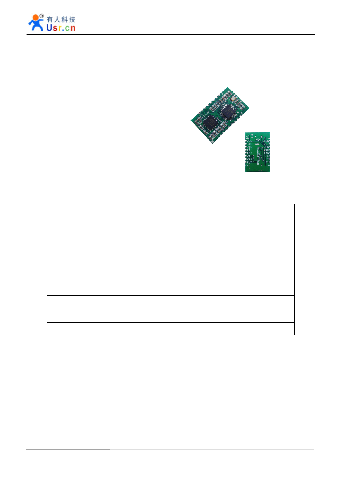
2.1 USR-TCP232-S
USR-TCP232-S
USR-TCP232-S Model Stamp Hole Package TTL
serial port level, the PHY signal, the small size of the
TCPIP serial protocol module .
Descriptio
Descriptio
Descriptio n
n
n
n
2.1.1
2.1.1
2.1.1
2.1.1 Technical
Technical
Technical
Technical Specifications
M
ajor
M
M
M ajor
Package Type Stamp hole encapsulation (SMD encapsulation )
Schematic diagram
and PCB library
Power Supply
Serial port level TTL level
Network interface PHY signal
Physical Siz e :
Temperature and
humidity range
Warranty period 2 years
characteristic
ajor
characteristic
ajor characteristic
characteristic P
Specifications
Specifications
Specifications
P
arameter
P
arameter
P arameter
arameter
See the CD library file
VCC: 3.3 V DC typical values, minimum 3.15, the biggest 3.45
suitable for 3.3 V microcontroller system
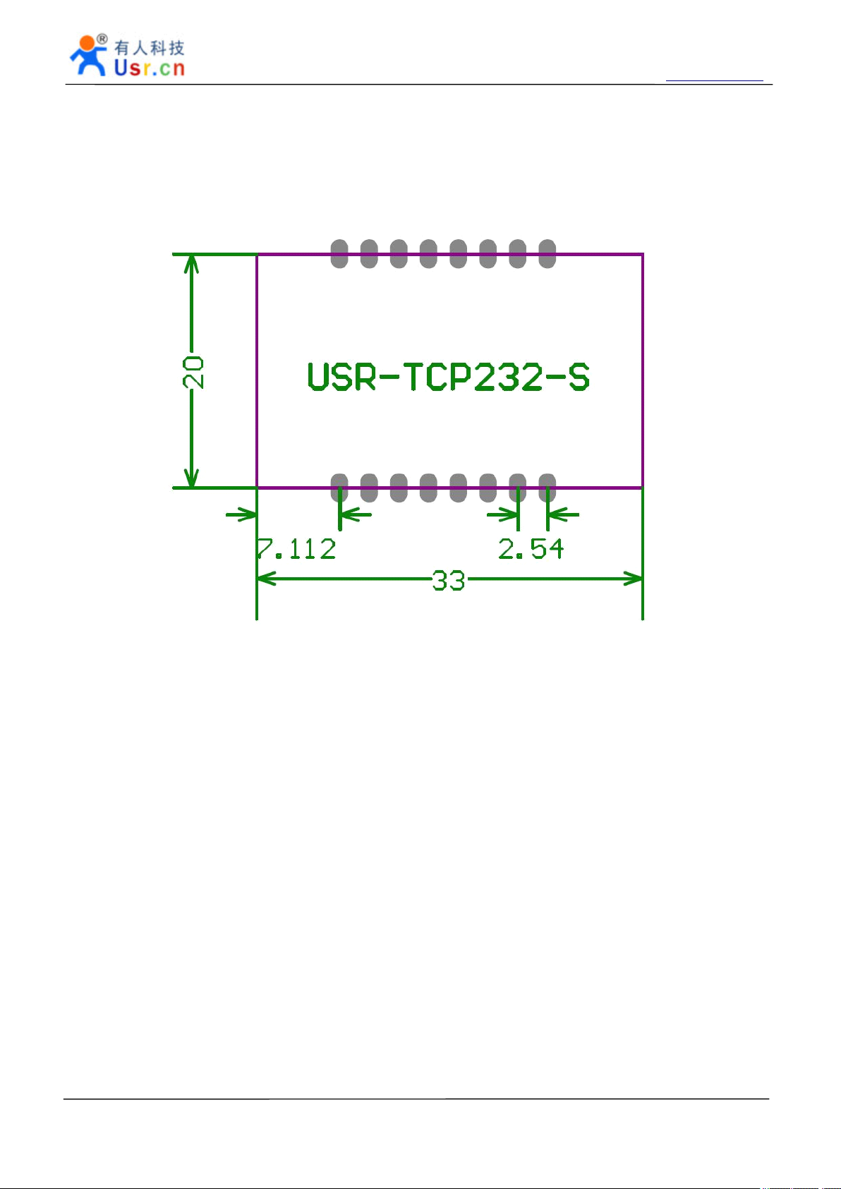
PCB size : 33*20mm ( L*W )
Operating temperature: -25 to 75 ° C
Storage temperature: -40 to 80 ° C
Storage humidity: 5% to 95% RH
V,
Jinan USR IOT Technology Limited Page 6 of 53 tec@usr.cn
Page 7
2
.1.2
2
2
2 .1.2
Hardware
.1.2
Hardware
.1.2 Hardware
Hardware Description
S erial to Ethernet module USR-TCP232-T24 series http://en.usr.cn
Description
Description
Description
2.1.21
2.1.21
2.1.21
2.1.21 Pin
Pin
Description
Pin
Description
Pin Description
Description
N
o.
N
N
N o.
Pin
o.
Pin
o. Pin
Pin Function
1 GND Signal ground GND
2 RST RESET
3 ISP Update pin
4 RXD
5 TXD Module data
6 CFG
Function
Function
Function Descrip
Module data is
received
transmission
Serial ports
Configuration pins
Descrip
Descrip
Descrip tions
Pin received 200ms low to reset the whole module.
If you do not use, can be suspended.
Note: The module is powered automatic reset, it is
recommended that connect the MCU IO port, reset the MCU
control module in a particular case.
This pin to ground to the module power module can be
upgraded.
If you do not use, can be suspended.
Data receiving end of the module, TTL level 5V or 3.3V
microcontroller
Data transmission end of the module, TTL level can be
connected to 5V or 3.3V microcontroller
Low, you can use the serial port module configuration.
Normal working hours left floating or tied HIGH.
Note: give the power module, and then pulled down the CFG
pin to enter the serial configuration state.
tions
tions
tions
7 LD2
8 LD1
9 2V5
10 RX+ Received signal + Receive Data+
11
RX- Received signal - Receive Data -
12 TX+ Transceiver Data+ Transceiver Data+
13 TX- Transceiver Data - Transceiver Data-
14 RTS the alternate pin Can be used as RS485 enable pin
15 CTS the alternate pin Can be used as a network connection status indicator pin
16 VCC Power supply Power supply : 3.3V @ 200mA
Network data
instructions
Network connection
status indicator
PHY chip
Output voltage
Network data indicator LED connected to VCC, without the
current limiting resistance (module existing)
Network connection status indicator LED connected to VCC,
without the current limiting resistor (module already)
PHY chip to control the voltage output, access networks
transformer center tap
Jinan USR IOT Technology Limited Page 7 of 53 tec@usr.cn
Page 8
S erial to Ethernet module USR-TCP232-T24 series http://en.usr.cn
2.1.22
2.1.22
2.1.22
2.1.22 Mechanical
Mechanical
Mechanical
Mechanical Dimensions
Unit: mm
Dimensions
Dimensions
Dimensions
Jinan USR IOT Technology Limited Page 8 of 53 tec@usr.cn
Page 9

S erial to Ethernet module USR-TCP232-T24 series http://en.usr.cn
2.1.23
2.1.23
2.1.23
2.1.23 Connection
Connection
Connection
Connection Diagram
Diagram
Diagram
Diagram
The network interface hardware connection diagram :
Jinan USR IOT Technology Limited Page 9 of 53 tec@usr.cn
Page 10

S erial to Ethernet module USR-TCP232-T24 series http://en.usr.cn
2.2
USR-TCP232-T
2.2
USR-TCP232-T
2.2
2.2 USR-TCP232-T
USR-TCP232-T
USR-TCP232-T Model pin package, TTL serial port
level, of 2KV electromagnetic isolation RJ45 interface, small
size TCPIP serial protocol module.
2.2.1
2.2.1
2.2.1
2.2.1 Technical
Technical
Technical
Technical Specifications
M
ajor
M
M
M ajor
Package Type
Schematic diagram and
PCB library
Power Supply
W orking current 150 m A , the maximum 200 m A
Serial port level TTL level
Network interface PHY signal
Physical Siz e :
Temperature and
humidity range
characteristic
ajor
characteristic
ajor characteristic
characteristic P
Specifications
Specifications
Specifications
P
arameter
P
arameter
P arameter
arameter
Pin type package (DIP package )
See the CD library file
T he module adopts double power supply interfaces, either is ok .
VCC:
VCC:
VCC:
VCC: 3.3 V DC typical values, minimum 3.15, the biggest 3.45
suitable for 3.3 V microcontroller system
VDD:
VDD:
VDD:
VDD: 5 V DC typical values, minimum 4.5 , the biggest 5.5
suitable for 5 V microcontroller system
PCB size : 50.5*22.6mm ( L*W )
Module size: 55*23*23 mm ( L * W * H )
Operating temperature: -25 to 75 ° C
Storage temperature: -40 to 80 ° C
Storage humidity: 5% to 95% RH
V,
V,
Warranty period 2 years
Jinan USR IOT Technology Limited Page 10 of 53 tec@usr.cn
Page 11

S erial to Ethernet module USR-TCP232-T24 series http://en.usr.cn
2.2.2
2.2.2
2.2.2
2.2.2 Hardware
2.2.21
2.2.21
2.2.21
2.2.21 Pin
Hardware
Hardware
Hardware Description
Pin
description
Pin
description
Pin description
description
P
in
P
in
P
P in
in N
VDD Power 1 4.5~5.5V
VCC Power 2 3.3V
GND GND Power and Communications Ground
RST Reset pin 200ms GND reset the module
TXD UART transmission pin 5v tolerance
RXD UART receive pin 5v tolerance
CFG Configure pin
Description
Description
Description
N
ame
N
ame
N ame
ame D
Configure mode when this pin GND, normal
mode when VCC or idle
D
escription
D
escription
D escription
escription
Module in the upper left four spare pins from
right to left :
Pin
Pin
Pin
Pin Name
LINK LINK a lternate p in Network connectivity status indicator pin
EN EN a lternate p i n RS485 enable pin
ISP Update pin
Name
Name
Name D
This pin to ground to the module power
module can be upgraded.
D
escription
D
escription
D escription
escription
Jinan USR IOT Technology Limited Page 11 of 53 tec@usr.cn
Page 12

S erial to Ethernet module USR-TCP232-T24 series http://en.usr.cn
2.2.22
2.2.22
2.2.22
2.2.22 LED
2.2.23
2.2.23
2.2.23
2.2.23 Mechanical
LED
LED
LED status
There are two leds in RJ45 connector, one is green, and the other is yellow.
Mechanical
Mechanical
Mechanical Dimensions
Unit: mm
status
status
status
LED
LED
LED
LED N
green Link state Light when 100Mbps network linked
yellow Data transfer Blink when there is data in or out
N
ame
N
ame
N ame
ame D
Dimensions
Dimensions
Dimensions
D
escription
D
escription
D escription
escription
2.2.24
2.2.24
2.2.24
2.2.24 Connection
Jinan USR IOT Technology Limited Page 12 of 53 tec@usr.cn
Connection
Connection
Connection Diagram
Diagram
Diagram
Diagram
MCU
51
,
AVR
,
PIC
51
,
AVR
,
PIC
51
51
,
,
AVR
AVR
,
,
PIC
PIC
Tx
+
Tx
+
Tx
Tx
+
GND
GND
GND
GND
TXD
TXD
TXD
TXD
RXD
RXD
RXD
RXD
,
ARM
,
ARM
,
,
ARM
ARM
VCC
GND
GND
GND
GND
RXD
RXD
RXD
RXD
TXD
TXD
TXD
TXD
USR
-
TCP 232
RS
232
to Ethernet
- T
VCC
+
Tx
Tx
Tx
Tx
Rx
Rx
Rx
Rx
Rx
Rx
Rx
Rx
1
-
-
-
-
2
+
+
+
+
3
-
-
-
-
6
Page 13
S erial to Ethernet module USR-TCP232-T24 series http://en.usr.cn
2.3
USR-TCP232-D
2.3
USR-TCP232-D
2.3
2.3 USR-TCP232-D
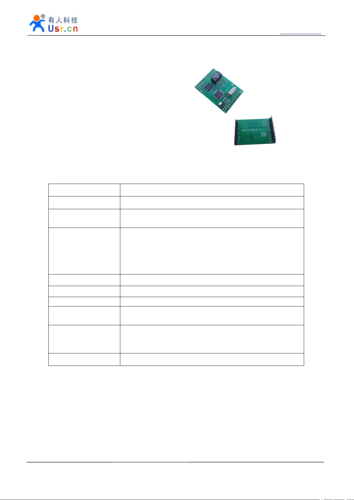
USR-TCP232-D
USR-TCP232-D models to pin package, TTL serial
port level, 1.5KV electromagnetic isolation PHY signal,
small size, TCPIP compatible weeks meritorious product
serial protocol module.
2.3.1
2.3.1
2.3.1
2.3.1 Technical
Technical
Technical
Technical Specifications
M
ajor
M
M
M ajor
Package Type
Schematic diagram and
PCB library
Power Supply
Serial port level TTL level
Network interface PHY signal with 1.5KV Ethernet signal
C haracteristic Pin compatible ZLG products
Physical Siz e :
Temperature and
humidity range
characteristic
ajor
characteristic
ajor characteristic
characteristic P
Specifications
Specifications
Specifications
P
arameter
P
arameter
P arameter
arameter
Pin type package (DIP package )
See the CD library file
T he module adopts double power supply interfaces, either is ok .
VCC:
VCC:
VCC:
VCC: 3.3 V DC typical values, minimum 3.15, the biggest 3.45
suitable for 3.3 V microcontroller system
VDD:
VDD:
VDD:
VDD: 5 V DC typical values, minimum 4.5 , the biggest 5.5
suitable for 5 V microcontroller system
PCB size: 44*32mm ( L*W )
Module size: 44* 32*15.4 mm ( L * W * H )
Operating temperature: -25 to 75 ° C
Storage temperature: -40 to 80 ° C
Storage humidity: 5% to 95% RH
V,
V,
Warranty period 2 years
Jinan USR IOT Technology Limited Page 13 of 53 tec@usr.cn
Page 14

2.
3
.2
2.
2.
2. 3
2.
2.
2.
2. 3
Hardware
3
.2
Hardware
3 .2
.2 Hardware
Hardware Description
3
.21
3
.21
3 .21
.21 Pin
Pin Name Description Pin Name Description
Description
Description
Description
Pin
Description
Pin
Description
Pin Description
Description
S erial to Ethernet module USR-TCP232-T24 series http://en.usr.cn
1 TX+ Transceiver Data+
2 TX- Transceiver Data- 23 NC
3 RX+
4 RX-
5 Data_LED Link to yellow Led and
6 TXD Transmit data 19 NC
7 RXD Receive data 18 ISP For Update
8 RTS RS485 enable pin 17 NC
9 CFG Config enable port for
10 RST Reset pin, 200ms low
11
12 GND
GND
To
RJ45 Pin3 22 NC
To
RJ45 Pin6 21 NC
20 NC
through a resistance to
VCC
16 3.3V DC3.3V input and5V use
RS232 Config
15 LINK Link to green Led and
for reset
To
GND 14 5V DC5V input @200mA
To
GND 13 5V DC5V input @200mA
A
breach here
1 is ok.
Through a resistance to
VCC
2.3.22
2.3.22
2.3.22
2.3.22 LED
Jinan USR IOT Technology Limited Page 14 of 53 tec@usr.cn
LED
LED
LED status
USR-TCP232-D Red LED, If the indicator is energized, the module power input is correct .
status
status
status
Page 15

S erial to Ethernet module USR-TCP232-T24 series http://en.usr.cn
2.3.23
2.3.23
2.3.23
2.3.23 Mechanical
Unit: mm
2.3.24
2.3.24
2.3.24
2.3.24 Connection
Mechanical
Mechanical
Mechanical Dimensions
Connection
Connection
Connection Diagram
Dimensions
Dimensions
Dimensions
Diagram
Diagram
Diagram
Note:
Note:
Note:
Note: Isolation transformer has been on this module, so you need not to add Isolation transformer in
your RJ45 port.
Jinan USR IOT Technology Limited Page 15 of 53 tec@usr.cn
Page 16
S erial to Ethernet module USR-TCP232-T24 series http://en.usr.cn
2.4
USR-TCP232-
2.4
USR-TCP232-
2.4
2.4 USR-TCP232-
USR-TCP232- 2
USR-TCP232- 2 Model is RS232 level, 2KV electromagnetic isolation RJ45 connector, USB type B or
terminals powered serial server.
2
2
2
2.4.1
2.4.1
2.4.1
2.4.1 Technical
Technical
Technical
Technical Specifications
M
ajor
M
M
M ajor
Power Supply DC 5V @ 1A power adapter
Serial port level RS232
Network interface RJ45 ports with 2KV electromagnetic isolation
Physical Siz e :
Temperature and
humidity range
Warranty period 2 years
characteristic
ajor
characteristic
ajor characteristic
characteristic P
Specifications
Specifications
Specifications
P
P
P arameter
PCB size: 67.3*34mm(L*W)
P roduct size : 86.6 × 34 × 25 mm ( L * W * H )
Operating temperature: -25 to 75 ° C
Storage temperature: -40 to 80 ° C
Storage humidity: 5% to 95% RH
arameter
arameter
arameter
Jinan USR IOT Technology Limited Page 16 of 53 tec@usr.cn
Page 17

2.4.
2
2.4.
2
2.4.
2.4. 2
2 Hardware
S erial to Ethernet module USR-TCP232-T24 series http://en.usr.cn
Hardware
Hardware
Hardware Description
Description
Description
Description
2.4.21
2.4.21
2.4.21
2.4.21 Pin
2.4.22
2.4.22
2.4.22
2.4.22 Interface
Power
Power
Power
Power i
power .
Pin
Description
Pin
Description
Pin Description
Description
There are two leds in RJ45 connector, one is green, and the other is yellow. And 1 power led.
LED N ame D escription
red Power Light When Power on
green Link state Light when 100Mbps network linked
yellow Data transfer Blink when there is data in or out
Interface
Interface
Interface Description
i
nterface
i
nterface
i nterface
nterface
DC5V power supply, you can make the B-type USB or 3.81mm pitch terminal blocks, terminal block
Description
Description
Description
RS232
RS232
RS232
RS232 interface
interface
interface
interface
RS232 use 9 pin female (hole), only 3 pins in use, others are NC, the detail is below.
R X D
G N D
T X D
5 4 3 2 1
9 8 7 6
ID Mark Description
2 TXD RS232 Send of module
3 RXD RS232 Receive of module
5 GND Ground
We can offer two kinds of serial cables , if needed, please choose to buy:
Male to Female direct serial cable: connect serial server and the computer directly to debugging and
Testing.
Male to Male and Cross Pin2 and Pin3 serial cable: used to connect RS232 serial port server and
general user equipment.
Jinan USR IOT Technology Limited Page 17 of 53 tec@usr.cn
Page 18

S erial to Ethernet module USR-TCP232-T24 series http://en.usr.cn
Note:
Note:
Note:
Note:
connection for the serial sensor supply via the serial line or external power to the device is not turned on by
default.
RJ45
RJ45
RJ45
RJ45 internet
Auto detected 10M/100M RJ45 interface, support AUTO MDI/MDIX , that is to say you can use crossover
cable or a straight cable to connect it to PC for test.
You
can DB9-9 feet supply. The PCB pads jumper need it with the power input a positive
internet
internet
internet interface
interface
interface
interface
Pin Name Description
1 TX+ Transceiver Data+
2 TX- Transceiver Data-
3 RX+ Receive Data+
4 n/c Not connected
5 n/c Not connected
6 RX- Receive Data-
7 n/c Not connected
8 n/c Not connected
2.4.23
2.4.23
2.4.23
2.4.23 Jumper
Jumper
Jumper
Jumper usage
usage
usage
usage Mechanical
Mechanical
Mechanical
Mechanical Dimensions
Dimensions
Dimensions
Dimensions
There are three jumpers and one Welding hole:
UPD: Update jumper, connect it and then power on the module to make module into update mode.
CFG: configuration jumper, when use RS232 for configuration, connect it to configuration mode ,and
leave it free to go work mode.
Notice: CFG is needed only When config via RS232, when config via RJ45, it is no use .
Jinan USR IOT Technology Limited Page 18 of 53 tec@usr.cn
Page 19

S erial to Ethernet module USR-TCP232-T24 series http://en.usr.cn
2.5
USR-TCP232-200
2.5
USR-TCP232-200
2.5
2.5 USR-TCP232-200
USR-TCP232-200
USR-TCP232-2 00 Model RS232 level, the 2KV electromagnetic isolation RJ45 interface, 5.5 * 2.1
standard power supply or terminal power supply serial server .
2.5.1
2.5.1
2.5.1
2.5.1 Technical
Technical
Technical
Technical Specifications
Ma
jor
Ma
Ma
Ma jor
Power Supply DC 5V @ 1A power adapter
Serial port level RS232
Network interface RJ45 ports with 2KV electromagnetic isolation
Physical Siz e :
Temperature and
humidity range
Warranty period 2 years
characteristic
jor
characteristic
jor characteristic
characteristic P
Specifications
Specifications
Specifications
P
P
P arameter
PCB size : 60*40mm(L*W)
P roduct size : 70 × 40 × 25 mm ( L * W * H )
Operating temperature: -25 to 75 ° C
Storage temperature: -40 to 80 ° C
Storage humidity: 5% to 95% RH
arameter
arameter
arameter
Jinan USR IOT Technology Limited Page 19 of 53 tec@usr.cn
Page 20

2.
5.2
2.
2.
2. 5.2
Hardware
5.2
Hardware
5.2 Hardware
Hardware Description
S erial to Ethernet module USR-TCP232-T24 series http://en.usr.cn
Description
Description
Description
2.5.21
2.5.21
2.5.21
2.5.21 Pin
2.5.22
2.5.22
2.5.22
2.5.22 Interface
Power
Power
Power
Power i
the default state is 5.5 * 2.1 standard power supply, power input with TVS protection products.
RS232
RS232
RS232
RS232 interface
Pin
Description
Pin
Description
Pin Description
Description
There are two leds in RJ45 connector, one is green, and the other is yellow. And 1 power led.
LED N ame D escription
red Power Light When Power on
green Link state Light when 100Mbps network linked
yellow Data transfer Blink when there is data in or out
Interface
Interface
Interface Description
i
nterface
i
nterface
i nterface
nterface
DC5V power supply, you can make 5.5 * 2.1 standard power supp l y or 3.81mm pitch terminal blocks,
interface
interface
interface The same as USR-TCP232-2.
Description
Description
Description
RJ45
interface
RJ45
interface
RJ45
RJ45 interface
interface The same as USR-TCP232-2.
Jinan USR IOT Technology Limited Page 20 of 53 tec@usr.cn
Page 21

S erial to Ethernet module USR-TCP232-T24 series http://en.usr.cn
2.5.23
2.5.23
2.5.23
2.5.23 Jumper
Jumper
Jumper
Jumper usage
usage
usage
usage Mechanical
Mechanical
Mechanical
Mechanical Dimensions
Dimensions
Dimensions
Dimensions
There are three jumpers and one Welding hole:
UPD: Update jumper, connect it and then power on the module to make module into update mode.
CFG: configuration jumper, when use RS232 for configuration, connect it to configuration mode ,and
leave it free to go work mode.
Notice: CFG is needed only When config via RS232, when config via RJ45, it is no use .
Jinan USR IOT Technology Limited Page 21 of 53 tec@usr.cn
Page 22

S erial to Ethernet module USR-TCP232-T24 series http://en.usr.cn
2.6
USR-TCP232-24
2.6
USR-TCP232-24
2.6
2.6 USR-TCP232-24
USR-TCP232-24
USR - TCP232-24 models for RS232 or RS485 level, 2 kv RJ45 interface of electromagnetic isolation,
5.5 * 2.1 standard power supply serial server.
2.6.1
2.6.1
2.6.1
2.6.1 Technical
Technical
Technical
Technical Specifications
M
ajor
M
M
M ajor
Power Supply DC 5V @ 1A power adapter
Serial port level
Network interface RJ45 ports with 2KV electromagnetic isolation
Physical Siz e :
Temperature and
humidity range
Warranty period 2 years
characteristic
ajor
characteristic
ajor characteristic
characteristic P
Specifications
Specifications
Specifications
P
P
P arameter
RS232
RS485
PCB size : 80*50mm(L*W)
P roduct size : 89.2 × 50 × 23 mm ( L * W * H )
Operating temperature: -25 to 75 ° C
Storage temperature: -40 to 80 ° C
Storage humidity: 5% to 95% RH
arameter
arameter
arameter
Jinan USR IOT Technology Limited Page 22 of 53 tec@usr.cn
Page 23

S erial to Ethernet module USR-TCP232-T24 series http://en.usr.cn
2.6.2
2.6.2
2.6.2
2.6.2 Hardware
2.6.21
2.6.21
2.6.21
2.6.21 LED
2.6.22
2.6.22
2.6.22
2.6.22 Interface
products.
Hardware
Hardware
Hardware Description
LED
LED
LED status
There are two leds in RJ45 connector, one is green, and the other is yellow. And 1 power led.
LED N ame D escription
green Power Light When Power on
green Link state Light when 100Mbps network linked
yellow Data transfer Blink when there is data in or out
Interface
Interface
Interface Description
Power
Power
Power
Power i
i
nterface
i
nterface
i nterface
nterface
DC5V power supply, you can make 5.5 * 2.1 standard power supply, power input with TVS protection
status
status
status
Description
Description
Description
Description
Description
Description
RS232
RS232
RS232
RS232 interface
interface
interface
interface
RS232 use 9 pin female (hole), only 3 pins in use, others are NC, the detail is below.
R X D
G N D
T X D
5 4 3 2 1
9 8 7 6
ID Mark Description
2 TXD RS232 Send of module
3 RXD RS232 Receive of module
5 GND Ground
We can offer two kinds of serial lines, if needed, please choose to buy:
1. Male to Female direct serial cable: connect serial server and the computer directly to debugging and
Testing.
2. Male to Male and Cross Pin2 and Pin3 serial cable: used to connect RS232 serial port server and
general user equipment.
Note:
Note:
Note:
Note:
Jinan USR IOT Technology Limited Page 23 of 53 tec@usr.cn
You
can DB9-9 feet supply. The PCB pads jumper need it with the power input a positive
Page 24

S erial to Ethernet module USR-TCP232-T24 series http://en.usr.cn
connection for the serial sensor supply via the serial line or external power to the device is not turned on by
default.
RS485
RS485
RS485
RS485 interface
interface
interface
interface
RS485 has two lines A(data+) and B(data-), 120 Ohms T ermination Resistance on board.
Notice:
Notice:
Notice:
Notice: this module user Jumpers to change work for RS232 or RS485, by default it work at RS232
mode.
RJ45
internet
RJ45
internet
RJ45
RJ45 internet
internet interface
interface
interface
interface
Auto detected 10M/100M RJ45 interface, support AUTO MDI/MDIX , that is to say you can use crossover
cable or a straight cable to connect it to PC for test.
Pin Name Description
1 TX+ Transceiver Data+
2 TX- Transceiver Data-
3 RX+ Receive Data+
4 n/c Not connected
5 n/c Not connected
6 RX- Receive Data-
7 n/c Not connected
8 n/c Not connected
Jinan USR IOT Technology Limited Page 24 of 53 tec@usr.cn
Page 25

S erial to Ethernet module USR-TCP232-T24 series http://en.usr.cn
2.6.23
2.6.23
2.6.23
2.6.23 Jumper
Jumper
Jumper
Jumper usage
usage
usage
usage Mechanical
Mechanical
Mechanical
Mechanical Dimensions
Dimensions
Dimensions
Dimensions
There are three jumpers and one Welding hole:
UPD: Update jumper, connect it and then power on the module to make module into update mode.
CFG: configuration jumper, when use RS232 for configuration, connect it to configuration mode ,and
leave it free to go work mode.
Notice: CFG is needed only When config via RS232, when config via RJ45, it is no use .
Jinan USR IOT Technology Limited Page 25 of 53 tec@usr.cn
Page 26

S erial to Ethernet module USR-TCP232-T24 series http://en.usr.cn
2.7
USR-TCP232-300
2.7
USR-TCP232-300
2.7
2.7 USR-TCP232-300
USR-TCP232-300
USR-TCP232-300 model products for RS232 or RS485 level, 2 kv RJ45 interface of electromagnetic
isolation, 5.5 * 2.1 standard power supply with a shell of a serial port server .
USR-TCP232-300 by USR-TCP232-24 shell, its specification please see USR - TCP232-24.
Jinan USR IOT Technology Limited Page 26 of 53 tec@usr.cn
Page 27

S erial to Ethernet module USR-TCP232-T24 series http://en.usr.cn
2.8
USR-TCP232-442
2.8
USR-TCP232-442
2.8
2.8 USR-TCP232-442
USR-TCP232-442
USR-TCP232-442 model products for RS485 or RS422 level, 2 kv RJ45 interface of electromagnetic isolation,
5.5 * 2.1 standard power supply or power supply terminal of a serial port server with shell .
2.8.1
2.8.1
2.8.1
2.8.1 Technical
Technical
Technical
Technical Specifications
M
ajor
M
M
M ajor
Power Supply DC 5 -18V power adapter
Serial port level
Network interface RJ45 ports with 2KV electromagnetic isolation
Physical Siz e :
Temperature and
humidity range
Warranty period 2 years
characteristic
ajor
characteristic
ajor characteristic
characteristic P
Specifications
Specifications
Specifications
P
P
P arameter
RS485
RS422
PCB size : 80*50mm(L*W)
P roduct size : 95*85*25mm ( L * W * H )
Operating temperature: -25 to 75 ° C
Storage temperature: -40 to 80 ° C
Storage humidity: 5% to 95% RH
arameter
arameter
arameter
Jinan USR IOT Technology Limited Page 27 of 53 tec@usr.cn
Page 28

S erial to Ethernet module USR-TCP232-T24 series http://en.usr.cn
2.8.2
2.8.2
2.8.2
2.8.2 Hardware
2.8.21
2.8.21
2.8.21
2.8.21 LED
2.8.22
2.8.22
2.8.22
2.8.22 Interface
Power
Power
Power
Power i
power input with TVS protection products.
RS
RS
RS
RS 485
Hardware
Hardware
Hardware Description
LED
LED
LED status
There are two leds in RJ45 connector, one is green, and the other is yellow. And 1 power led.
LED N ame D escription
red Power Light When Power on
green Link state Light when 100Mbps network linked
yellow Data transfer Blink when there is data in or out
Interface
Interface
Interface Description
i
nterface
i
nterface
i nterface
nterface
DC5V power supply, you can make 5.5 * 2.1 standard power supp l y and 3.81mm pitch terminal blocks,
485
interface
485
interface
485 interface
interface
status
status
status
Description
Description
Description
Description
Description
Description
RS485 has two lines A(data+) and B(data-) , the signal terminal 0.5A PTC Resettable Fuse, to prevent
accidental high current burn out the motherboard ; Professional TVS lightning protection circuit design ;
Internal 120R terminal matching resistor (the default is not used, the available short cap configured to use) ;
Can allow up to 32 transceiver node connected to the bus .
RS
422
RS
RS
RS 422
characteristics of superheated tube, can prevent the output short circuit ; Can allow up to 256 transceiver
node connected to the bus .
Notice:
Notice:
Notice:
Notice: RS485 and RS422 cannot be used at the same time , by default it work at RS 485 mode
RJ45
RJ45
RJ45
RJ45 internet
cable or a straight cable to connect it to PC for test.
interface
422
interface
422 interface
interface
RS422 lead wires are respectively
internet
internet
internet
Auto detected 10M/100M RJ45 interface, support AUTO MDI/MDIX , that is to say you can use crossover
Pin Name Description
1 TX+ Transceiver Data+
2 TX- Transceiver Data-
3 RX+ Receive Data+
4 n/c Not connected
5 n/c Not connected
6 RX- Receive Data-
7 n/c Not connected
8 n/c Not connected
A
(RX +), B (RX-), Y (TX +), Z (TX) G (GND) . Signal end has
Jinan USR IOT Technology Limited Page 28 of 53 tec@usr.cn
Page 29

S erial to Ethernet module USR-TCP232-T24 series http://en.usr.cn
2.8.23
2.8.23
2.8.23
2.8.23 Terminal
2.
8
2.
8
2.
2. 8
8 .2
Terminal
Terminal
Terminal functional
.2
4
Jumper
.2
4
Jumper
.2 4
4 Jumper
Jumper usage
functional
functional
functional specifications
usage
usage
usage Mechanical
specifications
specifications
specifications
Mechanical
Mechanical
Mechanical Dimensions
Dimensions
Dimensions
Dimensions
There are three jumpers and one Welding hole:
1. UPD: Update jumper, connect it and then power on the module to make module into update mode.
CFG: configuration jumper, when use RS232 for configuration, connect it to configuration mode ,and
leave it free to go work mode.
Notice: CFG is needed only When config via RS232, when config via RJ45, it is no use .
2. RS485 terminal resistance, the product is not added to the default state, if you want to use, please
use short circuit mo short answer the corresponding pin .
Jinan USR IOT Technology Limited Page 29 of 53 tec@usr.cn
Page 30

3
.
Work
3
.
Work
3
3 .
. Work
Work Mode
3.1
Block
3.1
Block
3.1
3.1 Block
Block diagram
Mode
Mode
Mode
diagram
diagram
diagram
S erial to Ethernet module USR-TCP232-T24 series http://en.usr.cn
power
TTL
User
device
Take
USR-TCP232-T
Take
USR-TCP232-T
Take
Take USR-TCP232-T
USR-TCP232-T for
3.
2
TCP
3.
2
TCP
3.
3. 2
2 TCP
TCP Client
In TCP client mode, after power on module according to their own Settings active TCP server to connect
to the server, and then establish a long connection, data transparent transmission after this mode, the TCP
server IP module would need to be visible and the visible means directly by module's IP can PING the server
IP,
server side can be fixed
network .
Client
Client
Client Mode
Mode
Mode
Mode
for
example,
for
example,
for example,
example, show
IP,
the Internet can also be internal network IP and module in the same local area
Serial to Ethernet
Converter
show
demo
show
demo
show demo
demo application
application
application
application of
Ethernet
of
module
of
module
of module
module USR-TCP232-T
USR-TCP232-T
USR-TCP232-T
USR-TCP232-T
1. Module try to connect to server
2. Data transfer through the connection
1 . Server listen a TCP port
MCU
51
,
AVR
,
PIC
,
51
,
51
51
,
,
3.3
UDP
3.3
UDP
3.3
3.3 UDP
UDP mode
In UDP mode, after the module is powered on listening on port Settings, not take the initiative to
establish a connection, when data from by forwarding to the serial port, when a serial port receives the data
sent over the network to the IP and port module Settings .
mode
mode
mode
ARM
AVR
,
PIC
,
ARM
AVR
AVR
,
,
PIC
PIC
,
,
ARM
ARM
COM
Module work at TCP Client mode
Ethernet
Jinan USR IOT Technology Limited Page 30 of 53 tec@usr.cn
Page 31

S erial to Ethernet module USR-TCP232-T24 series http://en.usr.cn
1. Module listen a UDP port
2. Data transfer With out connection, only data packet
1 . PC listen a UDP port
MCU
RS
51
,
AVR
,
PIC
,
51
,
AVR
51
51
,
,
AVR
AVR
ARM
,
PIC
,
ARM
,
,
PIC
PIC
,
,
ARM
ARM
232
Module work at UDP mode
3
.4
UDP
3
.4
UDP
3
3 .4
.4 UDP
UDP server
server
server
server Mode
Mode
Mode
Mode
UDP server refers to the normal UDP are not validated on the basis of the source IP address, destination
IP instead of the UDP packets are received data source
In this mode, the module by default record a destination
IP,
similar to TCP server functionality .
IP,
send data, at the same time, the module at the server status, to accept the network packets sent to module,
and adjust the target IP IP for the data source, suitable for multiple IP working mode for the module .
Ethernet
when a serial port data, to record the IP to
Use computer end program and UDP mode is exactly the same, no need to change .
1. Module listen a UDP port
2. Data transfer from Module to PC - A
MCU
51
,
AVR
,
PIC
,
51
,
51
51
,
,
ARM
AVR
,
PIC
,
ARM
AVR
AVR
,
,
PIC
PIC
,
,
ARM
ARM
COM
1 . PC listen a UDP port
Ethernet
Module work at UDP Server mode
P C - B S e n d a d a t a t o m o d u l e
t a r g e t I P t o p c
D a t a t r a n s f e r f r o m M o d u l e t o P C - B
M o d u l e c h a n g e t h e
PC
1
2
3
- A
PC
- B
Jinan USR IOT Technology Limited Page 31 of 53 tec@usr.cn
Page 32

S erial to Ethernet module USR-TCP232-T24 series http://en.usr.cn
3
.5
TCP
3
.5
TCP
3
3 .5
.5 TCP
TCP server
In TCP Server mode, module and gateway trying to communication first, and then monitor set up local
port, there is connection request response and create a connection, can exist at the same time up to 4 links, a
serial port after receipt of the data will be sent to all at the same time of establishing links with network module
device .
USR-TCP232-SETUP software, set the Index function can be achieved when to establish a
multi-channel connection, the module can identify communications equipment, and with the specified device
to communicate.
server
server
server Mode
Mode
Mode
Mode
Jinan USR IOT Technology Limited Page 32 of 53 tec@usr.cn
Page 33

3.6
Special
3.6
Special
3.6
3.6 Special
Special function
function
function
function s
S erial to Ethernet module USR-TCP232-T24 series http://en.usr.cn
s
s
s
3.61
3.61
3.61
3.61 RS485
product "EN" alternate pin for RS485, external enable control pin .
3.62
3.62
3.62
3.62 Link
communication Link pin will output low level, no connection is established, output high level .
alternate pin, external Link instructions.
RS485
RS485
RS485
USR-TCP232-S, USR-TCP232-T, USR-TCP232-D products "RTS" Alternate Pin USR-TCP232-200
Set the software interface :
Link
Link
Link
The Link pins for the module to establish a communication connection status indicates pin, establish the
U SR -TCP232-S "CTS" Alternate Pin USR-TCP232-T products, USR-TCP232-200 product " Link "
Set the software interface :
3.63
3.63
3.63
3.63 Rese
When the Reset function, the module tries to connect to TCP Server-side 30 times, still unable to establish a
connection, the module will automatically restart.
3.64
3.64
3.64
3.64 ID
the establishment of the connection or data communication process device ID will also be sent, the module ID
number is set to decimal, range 0 - 65535, requires the receiving end HEX format .
Rese
Rese
Rese t
When the module as a TCP Client-side, the module will take the initiative to connect TCP SERVER.
Set the software interface :
ID
ID
ID
Module as TCP Client-side ID function for TCP Server-side distinguish between data sources, to achieve
1. Select "Connect" to establish a communication connection, TCP Server-side will receive the
t
t
t
Jinan USR IOT Technology Limited Page 33 of 53 tec@usr.cn
Page 34

S erial to Ethernet module USR-TCP232-T24 series http://en.usr.cn
corresponding TCP Client-side ID (ID Description: The first four shows for the ID number, the last four digits
of the display ID negated to authentication).
The following picture shows the module do TCP CLINENT establish a communication connection ID
feature is enabled, the setup interface module ID number 12:
The figure below shows establish a communication connection ID function, the device through the serial
communication interface to the TCP Server-side:
Jinan USR IOT Technology Limited Page 34 of 53 tec@usr.cn
Page 35

S erial to Ethernet module USR-TCP232-T24 series http://en.usr.cn
2. Select data during each data transfer, TCP Server-side will receive the corresponding TCP Client-side
ID (ID Description: ID before data transmitted only display four-digit ID number).
The following picture shows the module do the TCP CLINENT ID feature is enabled, data transmission
module ID number 12 setting interface:
The figure below shows the data communication ID function, the device through the serial port to TCP
Server-side communication interface:
Jinan USR IOT Technology Limited Page 35 of 53 tec@usr.cn
Page 36

S erial to Ethernet module USR-TCP232-T24 series http://en.usr.cn
3.65
3.65
3.65
3.65 Index
time send data to four CLIENT and SERVER the receiving Client-side data can not distinguish between
sources of data, the Index function can send and receive data source selection.
specific parameters are described below :
49 represent incoming data, N represent client index.
out, N represent which client.
current link N accessed, total link number M.
Index
Index
Index
Module as TCP SERVER end up at the same time to establish four connections, server-side at the same
Index function is enabled, communication data is displayed corresponding Client side device number,
1.When receive data from ethernet, module will send data to serial port with head 49 N ,followed by data.
2.When user MCU want send data to module serial port, start with head 4F N data... 4F represent send
3.When new TCP connection incoming, module will send 43 N M to serial port, indicating that there is
4.When link number have exceed maximum, new link requir e ment will lead to message 46 46.
5.When disconnect, module will send 44 N M, represent current link N is delete, left link M.
Note:
Note:
Note:
Note: The above values set are HEX format
Set the software interface :
Data transmission as shown below:
3.66
3.66
3.66
3.66 RFC2217
Jinan USR IOT Technology Limited Page 36 of 53 tec@usr.cn
RFC2217
RFC2217
RFC2217
RFC2217 is an agreement for setup com port settings via Ethernet by socket, Our product support an
Page 37

S erial to Ethernet module USR-TCP232-T24 series http://en.usr.cn
agreement like that, but not standard RFC2217, it is more sample and easy than RFC2217 .
1. When module receive setup command, if is a valid command(right packet head and right checksum),
the module will change self setting and answer nothing, else the data bits would be sent out at com port.
2. TCP Client, TCP Server, UDP Client, UDP Server, UDP broadcast support this function .
3. All changes will work at once, but not save to module, when power off will lose the settings.
USR-TCP232-Setup V4.2.1 and later version support this function. Like follow picture.
The command length is 8 bits, detail as follow table. The demo bytes are in hex mode:
Name
Packet
header
Band rate UART bits setting Check sum
B ytes 3 3 1 1
Parity/data/stop
settings, see follow
table.
Description Three bytes
For example
(115200,N,8,1)
For example
(9600,N,8,1)
55 AA 55 01 C2 00 83 83
55 AA 55 00 25 80 83 83
Band rate in hex
mode, High byte first.
Check sum of
last 4 bytes
Jinan USR IOT Technology Limited Page 37 of 53 tec@usr.cn
Page 38

S erial to Ethernet module USR-TCP232-T24 series http://en.usr.cn
Appendix:
Appendix:
Appendix:
Appendix: UART bits setting detail
B it Description
1:0 Data bits 00 5 bits
2 Stop bits 0 1 bits
3 Parity enable 0 Not enable Parity
5:4 Parity type 00 ODD
8:6 Not used 000 Please fill 0
Test bits
55AA5501C2008346 For 115200 N,8,1
55AA550025808328 For 9600 N,8,1
V
alue D escription
01 6 bits
10 7 bits
11
8 bits
1 2 bits
1 E nable Parity
01 EVEN
10 Mark
11
Clear
Jinan USR IOT Technology Limited Page 38 of 53 tec@usr.cn
Page 39

S erial to Ethernet module USR-TCP232-T24 series http://en.usr.cn
4.
Configure
4.
Configure
4.
4. Configure
Configure
Module's working mode can be set as needed, we try my best to let the user work become simple, all did
not open advanced parameters, if you have special requirements, please contact us .
You
can set the work mode, the module IP and port, subnet mask, gateway, serial port baud rate, module
port, destination IP and port , c an be set through the serial port or network port are two ways to setup software
(USR-TCP232-Setup) .
4.1
C
4.1
4.1
4.1 C
onfigure
C
onfigure
C onfigure
onfigure command
Configure mode UART interface: 9600bps,n,8,1
prefix 2 0x55 0xAA 0x55 0xAA 0x55 0xAA
command
command
command format
part bytes description example hex
format
format
format
destination IP 4
destination
port
Host IP 4 The IP module hold 192.168.0.7 0x07 0x00 0xA8 0xC0
Host port 2 TCP/UDP source port 20108 0x8C 0x4E
Gateway 4
Work mode 1
baud rate 3 UART baud rate 115200 0x00 0xC2 0x01
Reserved 1 Reserved 00 0x00
checksum 1
destination IP 192.168.0.2
01
Destination port 8234 0x2A 0x20
2
Gateway IP 192.168.0.2
01
0x01: TCP Client
0x00: UDP
0x02: UDP Server
Sum(destination
destination port, host
host port, gateway, work
mode, baud rate,
reserved)
TCP mode 0x01
IP,
0xB9 0xB9
IP,
0xC9 0x00 0xA8 0xC0
0xC9 0x00 0xA8 0xC0
Full example : 00 A8 C0 2A 20 07 00 A8 C0 8C 4E C9 00 A8 C0 01 00 C2 01 00 B9
O nce in configure mode, the UART parameter change to 9600bps,n,8,1, and a ‘ U
send out to ensure the control MCU that in the configure mode. If the 24byte command has effect , a ‘ K’ascii
character is send back to control MCU. If configure command format error, an ‘ E’character will be send back
to control MCU. If the error is the checksum not match , the 1byte right checksum will be send back to control
MCU also.
Jinan USR IOT Technology Limited Page 39 of 53 tec@usr.cn
’
ascii character is
Page 40

S erial to Ethernet module USR-TCP232-T24 series http://en.usr.cn
4.2
C
4.2
4.2
4.2 C
network configuration to be airborne CFG pin module set through the serial port to receive instruction and to
change the operating parameters . USR-TCP232-Setup software to be modified, as follows :
parameters of the desired Settings ;
4.3
4.3
4.3
4.3 C
change the operating parameters . USR-TCP232-Setup software to be modified, as follows :
parameters of the desired Settings ;
onfigure
C
onfigure
C onfigure
onfigure through
In normal working condition, pulled down the CFG pin to enter the serial configuration state, through the
1.In ” use com port for setup ” fill in the correct COM number ;
2 . Click “ read via com ” ,t he left side will display the current configuration parameters, can modify the
3 . Click “ setup via com ” ,t o complete the module configuration ;
4. After Setting, left CFG free or connect to VCC, module begin work.
C
onfigure
C
onfigure
C onfigure
onfigure through
Under normal operating conditions, the module received through the network setting instruction, and
1. Click ” search in LAN ” ,t he left side will display the current configuration parameters, can modify the
2. Click ” setup in net ” ,t o complete the module configuration .
Since 2011-08-02, the new version modules support Setup via RJ45.
through
through
through RS
through
through
through RJ45
RS
RS
RS 232
RJ45
RJ45
RJ45
232
232
232
Jinan USR IOT Technology Limited Page 40 of 53 tec@usr.cn
Page 41

S erial to Ethernet module USR-TCP232-T24 series http://en.usr.cn
4.4
USR-TCP232-SETUP
4.4
USR-TCP232-SETUP
4.4
4.4 USR-TCP232-SETUP
USR-TCP232-SETUP
USR - TCP232 - the Setup software can be extended in functions to specific function module Settings, as
shown in the figure below .
5.
Test
5.
Test
5.
5. Test
Test Methods
5.1
General
5.1
General
5.1
5.1 General
General Test
Default setup is as below picture.
Methods
Methods
Methods
Test
Test
Test
Jinan USR IOT Technology Limited Page 41 of 53 tec@usr.cn
Page 42

S erial to Ethernet module USR-TCP232-T24 series http://en.usr.cn
Test:
1. material: pc with rs232( or use USB to rs232 cable) , 3.3V or 5V power , rs232 cable , Network Cable,
COM debug software, TCPIP debug software(in CD, also can be download).
2. Connection: connect module rs232 to pc rs232, RJ45 to pc RJ45 or the same router (same subnet).
Notice:
Notice:
Notice:
Notice: USE
USE
USE
USE TTL
TTL
TTL
TTL to
to
USB
to
USB
to USB
USB convert
convert
convert
convert or
or
or
or TTL
TTL
TTL
TTL to
to
RS232
to
RS232
to RS232
RS232 convert
convert
convert
convert
3. Power on the module 3.3V on VCC or 5V on VDD.
3. Setup PC IP to 192.168.0.201.
4. PING 192.168.0.7 (it is optional action)
4. open the software in CD, TCP server, listen port 8234, TCP server as
follow picture.
Jinan USR IOT Technology Limited Page 42 of 53 tec@usr.cn
Page 43

S erial to Ethernet module USR-TCP232-T24 series http://en.usr.cn
Click Listening, Open COM port .
The module will connect to the server and show the module IP and port.
Jinan USR IOT Technology Limited Page 43 of 53 tec@usr.cn
Page 44

S erial to Ethernet module USR-TCP232-T24 series http://en.usr.cn
5 . Now you can transfer data from PC RS232 to Ethernet.
You
can use other TCP UDP test software and COM port test software as you like.
Jinan USR IOT Technology Limited Page 44 of 53 tec@usr.cn
Page 45

S erial to Ethernet module USR-TCP232-T24 series http://en.usr.cn
5.2
V
5.2
5.2
5.2 V
Single-port TCP/IP - serial bridge (RFC 2217)
irtual
V
irtual
V irtual
irtual COM
COM
COM
COM
1 . setup the module
2. Install VSPM
3. Open VSPM ,
Add virtual COM.
Jinan USR IOT Technology Limited Page 45 of 53 tec@usr.cn
Page 46

S erial to Ethernet module USR-TCP232-T24 series http://en.usr.cn
4 . Setup as the follow pictures, you need to notice COM port, bond rate and work mode of PC, then click
Activate .
5 . After Activate click, a Virtual COM port COM2 , will be created, COM2 will receive data from TCP IP
socket, and send data to COM2 will convert to TCPIP socket data to remote Equipment .
If create failed, please notice to see error notice and log, when use Virtual COM Port, you should close
other software who use the same TCPIP port.
The success picture as follow:
Jinan USR IOT Technology Limited Page 46 of 53 tec@usr.cn
Page 47

S erial to Ethernet module USR-TCP232-T24 series http://en.usr.cn
At this point, you can use your equipment as an ordinary serial port, and operate of local virtual serial
port will converted to operation of the remote module RS 232. The figure is show send data between the two
serial port .
Jinan USR IOT Technology Limited Page 47 of 53 tec@usr.cn
Page 48

S erial to Ethernet module USR-TCP232-T24 series http://en.usr.cn
Test 100ms recycle send, send and receive 10,0000 bytes, every thing is ok.
Jinan USR IOT Technology Limited Page 48 of 53 tec@usr.cn
Page 49

S erial to Ethernet module USR-TCP232-T24 series http://en.usr.cn
6.
Apps
6.
Apps
6.
6. Apps
Apps
6.1
COM<->TCP/UDP<->server
6.1
COM<->TCP/UDP<->server
6.1
6.1 COM<->TCP/UDP<->server
COM<->TCP/UDP<->server
MCU use as RS
232
MCU
51
,
AVR
,
PIC
,
51
,
51
51
,
,
6.2
Virtual
6.2
Virtual
6.2
6.2 Virtual
Virtual COM
COM
COM
COM
Install VSPM software. The COM like installed in the pc.
MCU
51
51
51
51
ARM
AVR
,
PIC
,
ARM
AVR
AVR
,
,
PIC
PIC
,
,
ARM
ARM
RS
232
COM to Ethernet
MCU use as RS
,
AVR
,
PIC
,
ARM
,
AVR
,
PIC
,
ARM
,
,
AVR
AVR
,
,
PIC
PIC
,
,
ARM
ARM
RS
232
232
Socket software on
PC or hand system
VSPM run on PC
计算端通用
E t h e r
t
e
n
r
e
h
t
E
E
t
h
e
r
n
e
t
RS
232
操作
n e
t
MCU
51
51
51
51
Virtual COM mode
RS
232
232
communication system
,
AVR
,
PIC
,
ARM
,
AVR
,
PIC
,
ARM
,
,
AVR
AVR
,
,
PIC
PIC
,
,
ARM
ARM
Old RS
Jinan USR IOT Technology Limited Page 49 of 53 tec@usr.cn
Page 50

6.3
COM
6.3
COM
6.3
6.3 COM
COM <->
<->
TCP/UDP
<->
TCP/UDP
<-> TCP/UDP
TCP/UDP <->
S erial to Ethernet module USR-TCP232-T24 series http://en.usr.cn
<->
COM
<->
COM
<-> COM
COM
6.4
many
6.4
many
6.4
6.4 many
many COM
MCU
51
,
AVR
,
51
,
AVR
,
51
51
,
,
AVR
AVR
,
,
COM
COM
COM <->
PIC
PIC
PIC
PIC
,
ARM
,
ARM
,
,
ARM
ARM
<->
<->
<-> UDP
MCU use as RS
RS
232
MCU
51
,
AVR
51
,
AVR
51
51
,
,
AVR
AVR
UDP
UDP
UDP server
server
server
server <->
232
MCU use as RS
232
MCU
r n e
E t h e
Update to RS
remote
t
232
Communication
RS
232
51
,
AVR
,
PIC
,
51
51
51
ARM
,
AVR
,
PIC
,
ARM
,
,
AVR
AVR
,
,
PIC
PIC
,
,
ARM
ARM
MCU
RS
,
PIC
,
ARM
,
PIC
,
ARM
,
,
PIC
PIC
,
,
ARM
ARM
Old
<->
<->
<-> COM
232
Communication
COM
COM
COM
51
,
AVR
,
PIC
,
51
51
51
ARM
,
AVR
,
PIC
,
ARM
,
,
AVR
AVR
,
,
PIC
PIC
,
,
ARM
ARM
MCU
Module in Server
MCU MCU MCU
……
Module in
Client
When the UDP server COM transfer data to one of the many COM, the last COM that transferred data will be
Jinan USR IOT Technology Limited Page 50 of 53 tec@usr.cn
Page 51

S erial to Ethernet module USR-TCP232-T24 series http://en.usr.cn
choose.
6.5
COM<->
6.5
COM<->
6.5
6.5 COM<->
COM<-> TCP/UDP<->proxy
You
can use a proxy server to treat the data form one module to other, or just use you MCU to control the
module IP and destination IP Real-time. The method is pull CFG PIN to GND, and send the new configuration
data, then pull CFG pin to VCC to use new settings.
TCP/UDP<->proxy
TCP/UDP<->proxy
TCP/UDP<->proxy server
server
server
server <->TCP/UDP<->COM
<->TCP/UDP<->COM
<->TCP/UDP<->COM
<->TCP/UDP<->COM
M C U M C U M C U
M C U
M C UM C U
Jinan USR IOT Technology Limited Page 51 of 53 tec@usr.cn
Page 52

6.6
COM
6.6
COM
6.6
6.6 COM
COM <->
<->
TCP/UDP
<->
TCP/UDP
<-> TCP/UDP
TCP/UDP <->
S erial to Ethernet module USR-TCP232-T24 series http://en.usr.cn
<->
server
<->
server
<-> server
server
Server
Ethernet
Routing / Switch
EthernetEthernet
MCU
MCU MCU
MCU MCU MCU
Jinan USR IOT Technology Limited Page 52 of 53 tec@usr.cn
Page 53

S erial to Ethernet module USR-TCP232-T24 series http://en.usr.cn
7
.
Contact
7
.
Contact
7
7 .
. Contact
Contact us
Jinan USR IOT Technology Limited
A ddress : 1-523, Huizhan Guoji Cheng, Gaoxin Qu, Jinan, Shandong, China
T
el : 86- 531-55507297 86- 531-88826739 -803
Web: http:// en.usr.cn Skype: lisausr
Em ail : sales@usr.cn t ec@usr.cn
8
.
Doc
8
.
Doc
8
8 .
. Doc
Doc History
History
History
History
us
us
us
Version 1.0 2011-05-26
Version 1.1 2011-08-16 Add TCP Server mode, Add set via RJ45, modify virtual COM
Version 3.0 2013-04-25 T24 product series boil down to this specification
Jinan USR IOT Technology Limited Page 53 of 53 tec@usr.cn
 Loading...