

Page 1

USR-IO424T-EWR User Manual Technical Support: h.usriot.com
Jinan USR IOT Technology Limited www.usriot.com
1
USR-IO424T-EWR User Manual
File Version: V1.0.3.01
Page 2

USR-IO424T-EWR User Manual Technical Support: h.usriot.com
Jinan USR IOT Technology Limited www.usriot.com
2
Contents
USR-IO424T-EWR User Manual ......................................................................................................................... 1
Features .................................................................................................................................................................... 4
1. Get Start ................................................................................................................................................................ 5
1.1. Product introduction ............................................................................................................................... 5
1.2. Basic parameters .................................................................................................................................... 5
1.3. Hardware .................................................................................................................................................. 6
1.3.1. Interface ........................................................................................................................................ 6
1.3.2. LED .................................................................................................................................................. 6
1.3.3. Dimension ..................................................................................................................................... 7
1.4. Test............................................................................................................................................................. 7
1.4.1. Control by serial ........................................................................................................................... 8
1.4.2. Web Server .................................................................................................................................. 10
1.4.3. Control by USR Cloud ................................................................................................................. 10
2. Product function ................................................................................................................................................ 11
2.1. DI input .................................................................................................................................................... 11
2.1.1. Electrical level detection ............................................................................................................. 11
2.1.2. Buttons detection ........................................................................................................................ 11
2.1.3. Pulse counting ............................................................................................................................ 12
2.2. DO output ................................................................................................................................................ 12
2.3. AI input ................................................................................................................................................... 12
2.4. Temperature detection ......................................................................................................................... 13
2.5. Analog self-calibration ......................................................................................................................... 13
2.6. Work mode ............................................................................................................................................. 13
2.6.1. Master mode................................................................................................................................ 13
2.6.2. Slave mode ................................................................................................................................... 15
2.7. Upgrade firmware ................................................................................................................................. 16
2.8. Network ................................................................................................................................................... 16
2.8.1. Ethernet interface ..................................................................................................................... 16
2.8.2. WiFi .............................................................................................................................................. 17
2.9. Serial port ............................................................................................................................................... 17
2.9.1. Basic parameters ....................................................................................................................... 17
2.9.2. Configuration method ............................................................................................................... 17
2.10. Features ................................................................................................................................................ 18
2.10.1. Relay output status hold .......................................................................................................... 18
2.10.2. Conditional control .................................................................................................................. 18
2.10.3. Connect to remote server....................................................................................................... 20
2.10.4. Reset to default by hardware................................................................................................. 21
3. Modbus ............................................................................................................................................................... 22
3.1. Modbus frame ........................................................................................................................................ 22
3.2. Register distribution ............................................................................................................................ 22
4. Contact Us ........................................................................................................................................................... 25
5. Disclaimer .......................................................................................................................................................... 26
Page 3

USR-IO424T-EWR User Manual Technical Support: h.usriot.com
Jinan USR IOT Technology Limited www.usriot.com
3
6. Update History .................................................................................................................................................. 26
Page 4

USR-IO424T-EWR User Manual Technical Support: h.usriot.com
Jinan USR IOT Technology Limited www.usriot.com
4
Features
⚫ Support 4-way Relay output.
⚫ Support 4-way input, default is dry contact.
⚫ Support 2-way analog input, default are voltage detection.
⚫ Support 1-way PT100 temperature input.
⚫ Support 8 conditional control command.
⚫ Support Web Server to configure IO424T-EWR.
⚫ Support various function code: 0x01, 0x02, 0x03, 0x04, 0x05, 0x06, 0x0F, 0x10.
⚫ Support socket to connect to remote server and TCP Client.
⚫ Support two work modes: Master mode and Slave mode. Master mode supports connecting to multiple
Modbus RTU devices by RS485 cascading connection.
⚫ Adopt Modbus RTU protocol data processing. Support Modbus TCP/RTU protocol adaptation.
⚫ Support WAN/LAN interface.
⚫ Support connecting to USR Cloud.
⚫ Support FTP remote upgrade.
⚫ Support upgrading by RS485.
⚫ Support hardware watchdog.
⚫ Support various LED to indicate work status.
⚫ Support power supply over-current, over-voltage, anti-reverse connection protection.
Page 5
USR-IO424T-EWR User Manual Technical Support: h.usriot.com
Jinan USR IOT Technology Limited www.usriot.com
5
1. Get Start
If user has any question, please submit it back to customer center: h.usriot.com.
1.1. Product introduction
USR-IO424T-EWR is network IO product which supports 4-way input/output, 2-way analog quantity detection,
1-way temperature detection and Modbus RTU/TCP protocol. Take ‘Remote control’ as core function and have
high usability. User can easily and quickly integrate USR-IO424T-EWR into own system to realize remote control
which based on Ethernet and local control which based on LAN(WiFi) and RS485.
1.2. Basic parameters
Parameter
Value
Ethernet interface
Wired WAN/LAN interface
10/100M WAN/LAN *1
WiFi
Standard
Support 802.11b/g/n
Antenna
2.4G WiFi antenna
Range
100 meters in open area
Hardware parameters
Data interface
Serial port: Support RS485.
Baud rate: 300bps~230400bps
Working voltage
DC: 12V~36V
DI input
Dry contact input, just needing to short-circuit DI
and COM
DO output
AC 220V 5A
DC 28V 5A
Voltage acquisition
Range: 0V ~ 10V
Current acquisition
Range: 0mA ~ 20mA
Temperature detection
Range: -100℃ ~ 200 ℃
Working temperature
-20℃~+70℃
Storage temperature
-40℃~+85℃
Working humidity
5%~95%
Storage humidity
1%~95%
Dimension
123*114*28mm
Software parameters
Work mode
Master mode, slave mode
Configuration command
Modbus RTU
Network protocol
Modbus TCP, Modbus RTU
Application software
Support configuration software
Software function
DNS
Support
Data transmission mode
Support TCP Client
EMC level
ESD
IEC61000-4-2, Level 4
Surge
IEC61000-4-5, Level 3
Group pulse
IEC61000-4-4, Level 3
Figure 1 Basic parameters
Page 6

USR-IO424T-EWR User Manual Technical Support: h.usriot.com
Jinan USR IOT Technology Limited www.usriot.com
6
1.3. Hardware
1.3.1. Interface
Figure 2 Product interface diagram
➢ Antenna: WiFi antenna.
➢ Ethernet interface: Can be configured to LAN interface or WAN interface.
➢ RS485: RS485 interface.
➢ DO: DO1~DO4 are 4-way output and DO-COM is common interface.
➢ DI: Dry contact input and DI-COM is common interface.
➢ AI1, AI2: Analog input interface and reference ground connects to power supply negative pole. Default is
voltage acquisition mode and please contact to sales personnel if user needs current acquisition mode.
➢ PT100: PT100 three-wire system interface.
➢ Power supply: DC 12~36V power supply. Low power supply will cause IO424T-EWR can’t start.
1.3.2. LED
LED
Function
Status
POWER
Indicate power status
Light after powering module
WORK
Indicate system running status
Blink every 0.5 second after product system running;
Blink quickly during upgrading firmware process.
NET
Indicate network connection status
Light after connecting to remote server
WAN/LAN
Indicate WAN/LAN interface status
Light after connecting to network. Blink if has data
interaction.
Figure 3 LED
Page 7

USR-IO424T-EWR User Manual Technical Support: h.usriot.com
Jinan USR IOT Technology Limited www.usriot.com
7
1.3.3. Dimension
Figure 4 Dimension diagram
1.4. Test
➢ Connect PC to USR-IO424T-EWR by USB -> RS485 cable
➢ Connect IO424T-EWR’s Ethernet interface to make device connect to internet
➢ Connect antenna to IO424T-EWR and power the IO424T-EWR
➢ After powering on, please wait about 15 seconds and use PC or mobile to search IO424T-EWR’s WiFi
network(Default SSID is USR-IO424T+last four bytes of MAC address and password is www.usr.cn). Then
user’s PC or mobile can access internet.
Note: If user uses USR-IO424T-EWR firstly and can’t access internet with correct connection, it maybe the
following reason: LAN interface network segment is same as USR-IO424T-EWR’s LAN interface network segment.
The solution is: Enter USR-IO424T-EWR’s Web Server(Default IP address is 192.168.10.1) and modify LAN
interface IP address to other network segment, then restart device.
Page 8
USR-IO424T-EWR User Manual Technical Support: h.usriot.com
Jinan USR IOT Technology Limited www.usriot.com
8
1.4.1. Control by serial
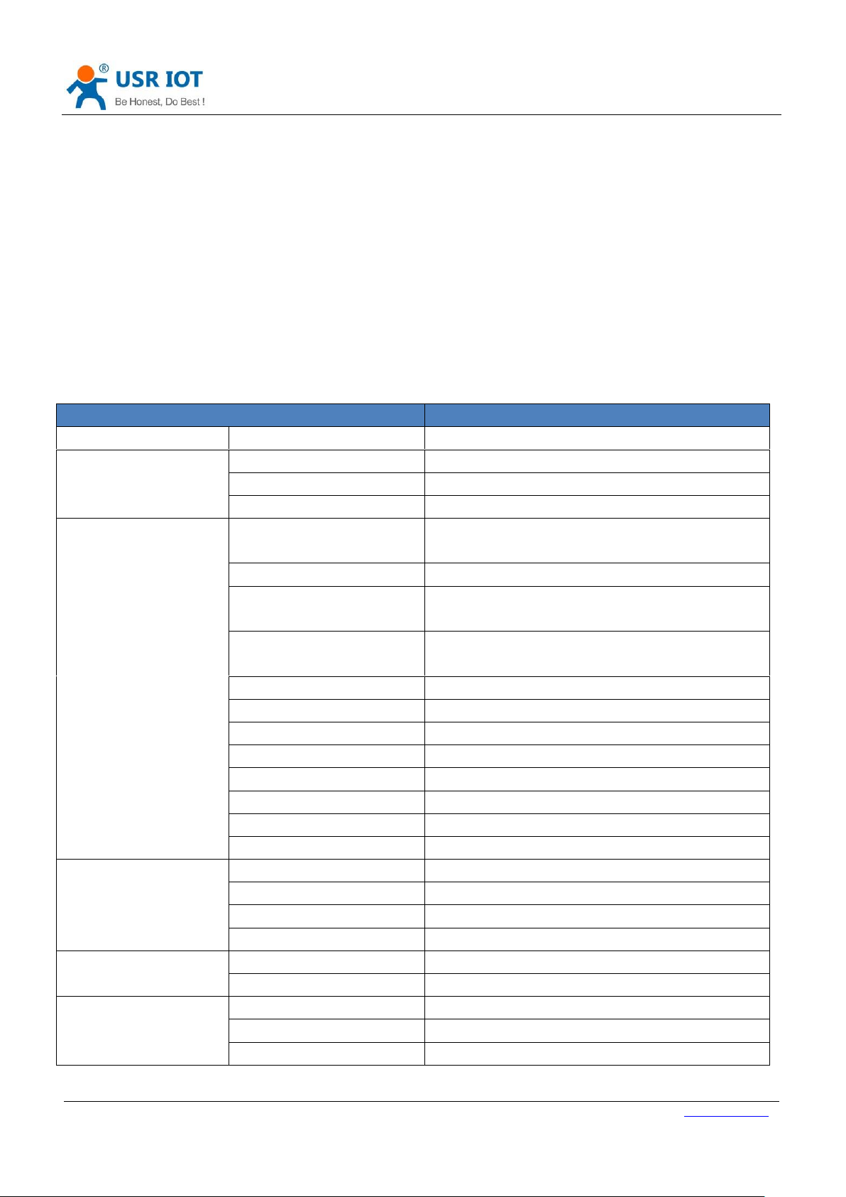
Power IO424T-EWR and connect IO424T-EWR’s RS485 interface to PC. Run setup software USR-IO V1.0.28.exe
and choose IO424T-EWR. Choose correct COM and configure correct serial port parameters as follow(Default
settings is 9600, None, 8, 1):
Figure 5 Open serial
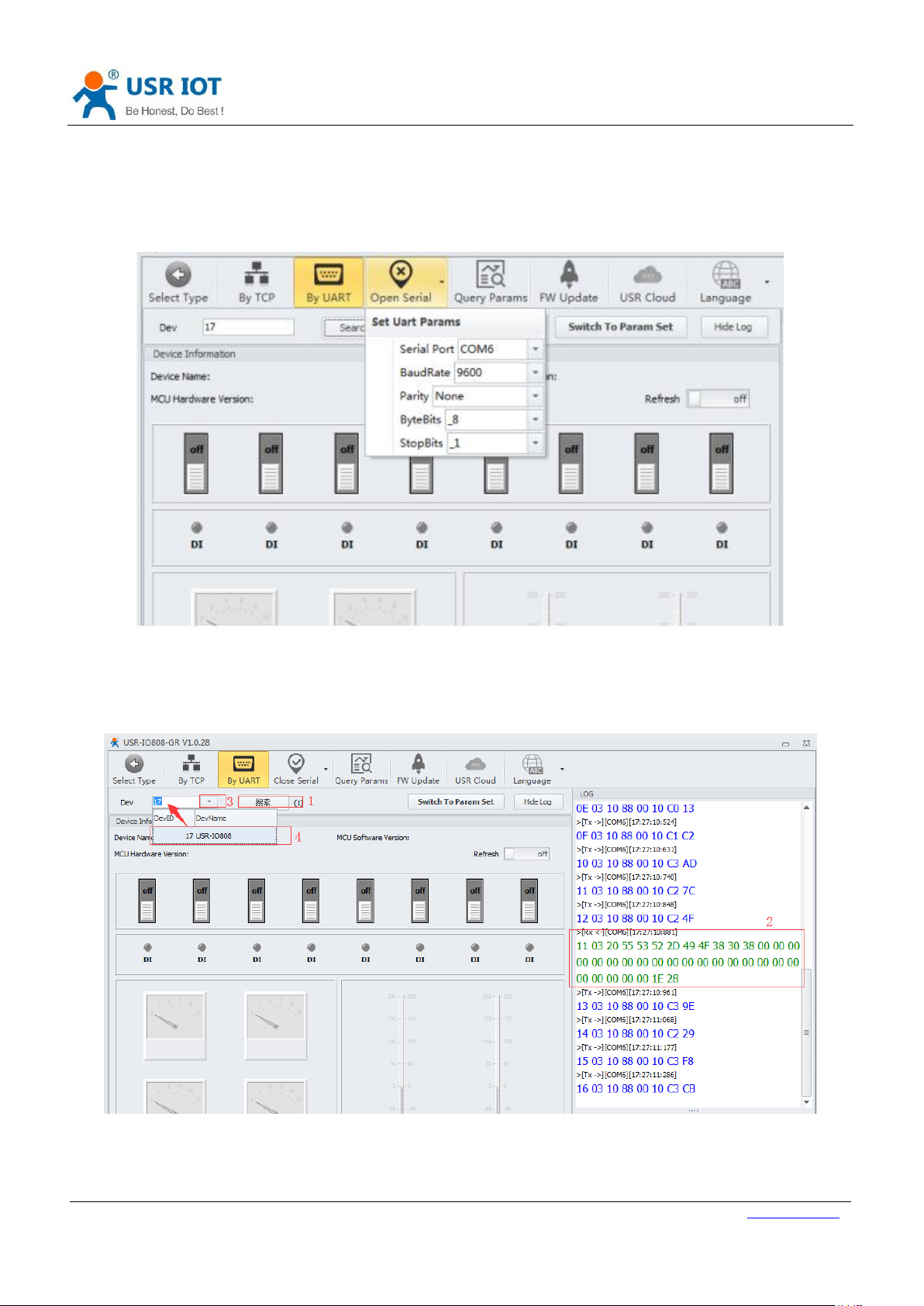
After opening serial port, click ’Search’ to search IO network controller and click ‘停止’ to stop searching after
finding IO network controller. Then choose IO network controller that user wants to configure.
Figure 6 Search IO network controller
Then user can control devices.
Page 9

USR-IO424T-EWR User Manual Technical Support: h.usriot.com
Jinan USR IOT Technology Limited www.usriot.com
9
Figure 7 Control devices
User can also click ‘Switch To Param Set’ on above figure to enter IO424T-EWR configuration page.
Figure 8 Configuration page
Page 10

USR-IO424T-EWR User Manual Technical Support: h.usriot.com
Jinan USR IOT Technology Limited www.usriot.com
10
1.4.2. Web Server
The initial parameter of USR-IO424T-EWR to enter Web Server as follow:
Work mode
Network data transparent transmission
Username
admin
Password
admin
LAN interface IP address
192.168.10.1
Figure 9 Initial parameter of USR-IO424T-EWR to enter Web Server
Type 192.168.10.1 into browser address bar and log in with username and password(Both are admin). Then user
can query and configure parameters of USR-IO424T-EWR by Web Server.
1.4.3. Control by USR Cloud
User can type http://console.usr.cn/ into browser address bar to enter USR Cloud web page and login with
username and password. Then user can add device as follow:
Figure 10 Add IO424T-EWR
Choose ‘Networking I/O controller’ as ‘Device type’, write IMEI and SN on IO424T-EWR’s label and click ‘Save’ to
add IO424T-EWR.
After adding IO424T-EWR, power IO424T-EWR and wait LED ‘NET’ light which means IO424T-EWR connects to
USR Cloud. Then user can remotely look over, record and control IO424T-EWR status in real time through USR
Cloud(Monitor->Data list).
Page 11

USR-IO424T-EWR User Manual Technical Support: h.usriot.com
Jinan USR IOT Technology Limited www.usriot.com
11
2. Product function
USR-IO424T-EWR functional diagram as follow:
Serial port
device(Should
support
Modbus RTU
protocl)
Network
server
Modbus protocol mode
Execute Modbus protocol
RS485
Data transparent transmission mode
RTU check
Data transparent
transmission
RTU check
Communication
module
Modbus
TCP/RTU
protocol
conversion
Input
Output
Switch input
Relay output
Serial
packaging
Temperature
Analog
quantity
PT100
Analog sensor
Figure 11 Functional diagram
2.1. DI input
2.1.1. Electrical level detection
➢ Register address range: 32~35(0x0020~0x0023)
➢ Supported function code: 02(Read discrete input), 03(Read holding register)
➢ Connection: Default is dry contact input. Short-circuit DI and COM will change input status. If user needs wet
contact input can contact to our sales personnel
➢ Electrical level detection: Default status is 0, after short-circuiting DI and COM, status will be 1. Detection
method: 02 function code of Modbus protocol.
Example:
Detect input of the first way, send: 11 02 00 20 00 01 BA 90
Short-circuiting will return: 11 02 01 01 64 88
No short-circuiting will return: 11 02 01 00 A5 48
2.1.2. Buttons detection
➢ Register address range: 48~51(0x0030~0x0033)
➢ Supported function code: 03(Read holding register), 04(Read input register)
➢ Connection: Default is dry contact input. Short-circuit DI and COM will change input status. If user needs wet
contact input can contact to our sales personnel
➢ Electrical level detection: Default status is 0000, after short-circuiting DI and COM and then releasing, status
will be FF00. Detection method: Read button register value by 03 function code of Modbus protocol. After
reading once button register, status will recover to 0000; after executing conditional control, status will also
recover to 0000.
Example:
Detect the first way button, send: 11 03 00 30 00 01 86 95
No button will return: 11 03 02 00 00 79 87
Page 12

USR-IO424T-EWR User Manual Technical Support: h.usriot.com
Jinan USR IOT Technology Limited www.usriot.com
12
Have button will return: 11 03 02 FF 00 38 77
2.1.3. Pulse counting
➢ Register address range: 64~67(0x0040~0x0043)
➢ Supported function code: 03(Read holding register), 04(Read input register)
➢ Connection: Default is dry contact input. Short-circuit DI and COM will change input status. If user needs wet
contact input can contact to our sales personnel
➢ Pulse counting: Default status is 0, short-circuit DI and COM and then release will count 1. Detection method:
Read pulse counting register value by 03 function code of Modbus protocol. Maximum value of pulse counting
is 65535 and it will restart counting after exceeding 65535. Can’t reset count to 0 and restart product won’t
save count.
➢ Note: Pulse counting won’t filter input waveform and all pulse in the range of detection will be recorded. So
input waveform should keep stable to ensure accurate count.
Example:
Detect count of the first way, send: 11 03 00 40 00 01 87 4E
Return: 11 03 02 00 00 79 87
2.2. DO output
➢ Register address range: 00~03(0x0000~0x0003)
➢ Supported function code: 01(Read coil), 05(Write single coil), 0F(Write multiple coil)
➢ Connection: DO output is Relay passive output and 4-way will use one COM together. Relay close will connect
DO with COM.
Take the first way Relay control as example:
Query: 11 01 00 00 00 04 3F 59
Control to close: 11 05 00 00 FF 00 8E AA
Control to disconnect: 11 05 00 00 00 00 CF 5A
2.3. AI input
➢ Register address range: 88~89(0x0058~0x0059, voltage acquisition data), 96~97(0x0060~0x0061, current
acquisition data)
➢ Supported function code: 03(Read holding register), 04(Read input register)
➢ Connection: Analog detection adopts public reference ground method to connect(signal + connects to +,
signal - connects to - and reference ground short-circuit to power ground). Voltage detection range: 0 ~ 10V;
current detection range: 0 ~ 20mA.
Take the first way voltage detection as example:
Query: 11 03 00 58 00 01 07 49
Return: 11 03 02 10 00 74 47
Return data: 0x1000, it’s 4096 mV
Note: Analog detection is voltage detection and current detection, default is voltage detection and please ignore
current register value. If user needs to do 0~20mA current detection, please contact to our sales personnel.
Page 13

USR-IO424T-EWR User Manual Technical Support: h.usriot.com
Jinan USR IOT Technology Limited www.usriot.com
13
2.4. Temperature detection
➢ Register address range: 80(0x0050, temperature acquisition data)
➢ Supported function code: 03(Read holding register), 04(Read input register)
➢ Connection: Input signal of temperature detection is PT100 signal and connection adopts three-wire system.
Single wire connects to + and two interlinked wires connect to two -.
➢ Temperature calculation formula: Actual temperature=(Return value-10000)/100
Example:
Query: 11 04 00 50 00 01 33 4B
Return: 11 04 02 06 92 FA FE
Return data: 0x0692, it’s 1682 and actual temperature=(1682-10000)/100=-83.18℃
2.5. Analog self-calibration
USR-IO424T-EWR supports analog self-calibration(Include two-way voltage value and one-way temperature value
calibration).
➢ Temperature 1 self-calibration register address: 0x00B7~0x00B8
➢ Voltage 1 self-calibration register address: 0x00C7~0x00C8
➢ Voltage 2 self-calibration register address: 0x00C9~0x00CA
Every analog self-calibration will occupy two register address. For example, 0x00B7 and 0x00B8 are temperature
self-calibration register address. Factory default value of two register address both are 10000, prior register
address value represents K and last register address value represents B.
Calculation formula of temperature self-calibration: Temperature output value=(K/10000)*original temperature
output value+(B-10000)/100
Calculation formula of voltage self-calibration: Voltage output value=(K/10000)*original voltage output
value+(B-10000)*10
2.6. Work mode
Default work mode of USR-IO424T-EWR is slave mode. IO424T-EWR will be slave both on network side and RS485
side and IO424T-EWR will discard data if IO424T-EWR receives data not for IO424T-EWR local address.
2.6.1. Master mode
Master mode data flow diagram and connecting to network diagram as follows:
Page 14

USR-IO424T-EWR User Manual Technical Support: h.usriot.com
Jinan USR IOT Technology Limited www.usriot.com
14
Figure 12 Master mode data flow
Figure 13 Connecting to network in Master mode
In master mode, server can communicate to network IO product IO424T-EWR and Modbus devices which connect
to IO424T-EWR’s RS485 interface. RS485 side can also transmit data to IO424T-EWR directly.
User can configure IO424T-EWR to Master mode by setup software as follow(Configure RS485 mode to 1.DTU):
Page 15

USR-IO424T-EWR User Manual Technical Support: h.usriot.com
Jinan USR IOT Technology Limited www.usriot.com
15
Figure 14 Configure IO424T-EWR to Master mode
2.6.2. Slave mode
Slave mode data flow diagram and connecting to network diagram as follows:
Figure 15 Slave mode data flow
Figure 16 Connecting to network in Slave mode
In this mode, IO424T-EWR can communicate to network server and Modbus devices on RS485 network. But
network server can’t communicate to Modbus devices on RS485 network.
Page 16

USR-IO424T-EWR User Manual Technical Support: h.usriot.com
Jinan USR IOT Technology Limited www.usriot.com
16
User can configure IO424T-EWR to salve mode by setup software as follow(Configure RS485 mode to
2.RTUSLAVE):
Figure 17 Configure IO424T-EWR to Slave mode
2.7. Upgrade firmware
User can refer to FAQ <<Upgrading firmware method of USR-IO424T-EWR_V1.0.0>>.
2.8. Network
2.8.1. Ethernet interface
USR-IO424T-EWR’s Ethernet interface supports switching between WAN interface and LAN interface. By
modifying value of corresponding register, USR-IO424T-EWR can realize WAN/LAN switch. User can configure by
setup software as follow:
Figure 18 WAN/LAN switch
Page 17

USR-IO424T-EWR User Manual Technical Support: h.usriot.com
Jinan USR IOT Technology Limited www.usriot.com
17
2.8.2. WiFi
USR-IO424T-EWR supports WiFi function and AP/STA two WiFi modes,
AP mode:
1. Set WiFi mode to 1(AP mode) and AP’SSID/AP’s password, then restart device.
2. After restarting successfully, use PC or mobile to search IO424T-EWR and connect.
STA mode:
1. Set WiFi mode to 2(STA mode) and SSID/password of the target AP which user wants to connect IO424T-EWR
to, then restart device.
2. After restarting successfully, IO424T-EWR will connect to target AP automatically.
Figure 19 WiFi mode
2.9. Serial port
2.9.1. Basic parameters
Parameter
Range
Baud rate
300~230400
Data bits
7, 8
Stop bits
1, 2
Parity
NONE, EVEN, ODD
Figure 20 Serial port basic parameters
2.9.2. Configuration method
Serial port parameters occupy two registers. Length of protocol is 4 bytes and specific protocol content as
follow(All examples are in HEX format):
Name
Baud rate
Parameter bit
Number of bytes
3
1
Description
Three bytes represent a baud rate
value and high-order in the former
Refer to Figure 22 Serial port
parameter bit
Example 1(115200, None, 8, 1)
01 C2 00
03
Example 2(9600, None, 8, 1)
00 25 80
03
Figure 21 Serial port parameters protocol
Page 18

USR-IO424T-EWR User Manual Technical Support: h.usriot.com
Jinan USR IOT Technology Limited www.usriot.com
18
Bit number
Representation
Value
Description
1:0
Data bits
10
7 bits data bits
11
8 bits data bits
2
Stop bits
0
1 bit stop bits
1
2 bits stop bits
5:4:3
Parity
000
None
001
ODD
011
EVEN
7:6
No definition
00
Please write 0
Figure 22 Serial port parameter bit
2.10. Features
2.10.1. Relay output status hold
User can configure whether hold Relay output status: After restarting IO424T-EWR or powering on IO424T-EWR
again, hold the Relay output status or reset to disconnect status.
➢ Register address: 182(0x00B6)
➢ Parameter values: 1(0x0001):All Relays hold status after restarting or powering off. 2(0x0002):All relays hold
status after restarting and don’t hold status after powering off.3(0x0003):All relays don’t hold status after
restarting or powering off.
➢ Supported function code: 0x03, 0x04, 0x06, 0x10
Configuration will take effect after restarting.
2.10.2. Conditional control
Conditional control function supports user configuring the conditions to trigger IO changes. It can make using
IO424T-EWR more flexibly and extend application scenario. User only needs to modify conditional control
function register parameters according to the instructions , it will realize corresponding function.
Conditional control function has 32 registers and 8 conditional control commands(Every command occupies 4
registers). Registers distribution as follow:
Storage content
Input register
Output register
Output action
Condition
Threshold
Reserved
Length
1 byte
1 byte
1 byte
1 byte
2 bytes
2 bytes
Address
Range:
16~109
Range: 1~16
1: Disconnect
2: Close
3: Reversal
1 ~ 255
‘Compared
register
values’/The first
two bytes of
time-stamp
Reserved/
Last two
bytes of
time-stam
p
Figure 23 Conditional control function register
➢ Output action(Relay output)
1: Disconnect
Page 19

USR-IO424T-EWR User Manual Technical Support: h.usriot.com
Jinan USR IOT Technology Limited www.usriot.com
19
2: Close
3: Reversal
➢ Condition
1: Forward direction output follow
2: Backward direction output follow
3: Greater than or equal to
4: Less than or equal to
255: Button action
➢ Control mode
Switching value control: DI input control DO output directly
Semaphore control: DI button semaphore control DO. Press button once, DO act once(Execute action in rising
edge of releasing button).
Detailed explanation:
1. Forward direction output follow
Enable forward direction output follow: Set condition register to 1, input register is corresponding to one way
register address of 4-way input and output register is corresponding to one way register address of 4-way output.
For example, if configure as 0x20 0x00 0x01 0x01 0x00 0x00 0x00 0x00, it represents status of DO1 will follow
status of DI1 which means DO1 will close if DI1 close and DO1 will disconnect if DI1 disconnect.
2. Backward direction output follow
Enable backward direction output follow: Set condition register to 2, input register is corresponding to one way
register address of 4-way input and output register is corresponding to one way register address of 4-way output.
For example, if configure as 0x20 0x00 0x01 0x02 0x00 0x00 0x00 0x00, it represents status of DO1 will be
opposite as status of DI1 which means DO1 will close if DI1 disconnect and DO1 will disconnect if DI1 close.
3. Button control
Enable button control: Set condition register to 255, input register is DI button register and output register is DO
output register. Action can be 1(disconnect ), 2(close), 3(reversal ), threshold register and reserved register can’t
work.
For example, if configure as 0x30 0x00 0x03 0xFF 0x00 0x00 0x00 0x00, it represents detecting DI1 button once
will reverse status of DO1 once.
4. Greater than or equal to
Condition of greater than or equal to action is 03. Input register are voltage register, current register and
temperature register; output register is DO output register. Action can be 1(disconnect ), 2(close), 3(reversal ).
Threshold register is comparison value and program will compare acquisition results of input register with
comparison value. Reserved register can’t work.
For example, if configure as 0x50 0x00 0x01 0x03 0x3A 0x98 0x00 0x00, it represents: 0x50 is the first way
temperature acquisition and 0X3A98 represents 15000(50℃). This condition represents disconnecting the first
Page 20

USR-IO424T-EWR User Manual Technical Support: h.usriot.com
Jinan USR IOT Technology Limited www.usriot.com
20
way DO output when the first way temperature acquisition result is greater than 50℃.
5. Less than or equal to
Condition of less than or equal to action is 04. Input register are voltage register, current register and temperature
register; output register is DO output register. Action can be 1(disconnect ), 2(close), 3(reversal ). Threshold
register is comparison value and program will compare acquisition results of input register with comparison
value. Reserved register can’t work.
For example, if configure as 0x50 0x00 0x01 0x04 0x3A 0x98 0x00 0x00, it represents: 0x50 is the first way
temperature acquisition and 0X3A98 represents 15000(50℃). This condition represents disconnecting the first
way DO output when the first way temperature acquisition result is less than or equal to 50℃.
Note:
Input register is 0 means close this conditional control and execute button action once will clear button register. If
multiple conditions will lead to paradoxical result, program will execute two results quickly. If forward direction
output follow and backward direction output follow lead to paradoxical result, disconnecting and closing will
revolve.
2.10.3. Connect to remote server
User can modify related register parameters of remote server to realize IO424T-EWR connecting to remote server.
Procedure as follow:
1. Power the IO424T-EWR and connect IO424T-EWR’s RS485 interface to PC. Run setup software(User can refer
to 1.4.1.Control by serial), modify remote server address and remote port as follow:
Figure 24 Configure remote server parameters
2. Restart IO424T-EWR to make configuration take effect.
3. Login remote server and open the port.
4. Wait IO424T-EWR LED ‘NET’ light which means IO424T-EWR connect to remote server successfully, Then user
can transmit Modbus TCP/RTU command from server side to control IO424T-EWR and receive response from
IO424T-EWR.
Page 21

USR-IO424T-EWR User Manual Technical Support: h.usriot.com
Jinan USR IOT Technology Limited www.usriot.com
21
2.10.4. Reset to default by hardware
User can reset to default settings by pressing Reload button. After powering on, press Reload button 3 seconds to
15 seconds, then release it, IO424T-EWR will reset to default settings. Less than 3 seconds or more than 15
seconds will be considered as misoperation and don’t handle it.
Page 22

USR-IO424T-EWR User Manual Technical Support: h.usriot.com
Jinan USR IOT Technology Limited www.usriot.com
22
3. Modbus
3.1. Modbus frame
Modbus RTU:
Figure 25 Modbus RTU frame
USR-IO424T-EWR data format conform to general Modbus frame format. IO424T-EWR can analyse Modbus RTU
protocol and execute related operations.
Modbus TCP:
Figure 26 Modbus TCP frame
USR-IO424T-EWR can analyse received network Modbus TCP protocol data and transfer to Modbus RTU protocol
to do data processing. IO424T-EWR can also be used in Master mode and transfer Modbus RTU protocol to
Modbus TCP protocol and transmit to server.
3.2. Register distribution
USR-IO424T-EWR register instructions:
1. Register base address is 0x0000.
2. In following register distribution table, MCU parameters and communication module parameters must operate
together.
3. Setup software USR-IO adopts UTF-8 coded format.
4. Register store HEX format data.
Register address
Register content
Parameter description
Applicable function code
Device I/O
0x0000~0x0003
Switch value output
0xFF00 means ON, 0x0000
means OFF;
1 means ON, 0 means OFF
0x01, 0x05, 0x0F
Page 23

USR-IO424T-EWR User Manual Technical Support: h.usriot.com
Jinan USR IOT Technology Limited www.usriot.com
23
0x0020~0x0023
Switch value input
1 means ON, 0 means OFF
0x02
0x0030~0x0033
Button input
Button detection. Reset to 0
after reading once
0x03, 0x04
0x0040~0x0043
Pulse counting
Count range: 0~65535. Reset
to 0 after reaching maximum
0x03, 0x04, 0x06, 0x10
0x0050
Temperature detection
PT100 temperature detection,
range: -100~200℃
0x03, 0x04
0x0058
Voltage 1 detection
0-10V voltage detection
0x03, 0x04
0x0059
Voltage 2 detection
0-10V voltage detection
0x03, 0x04
MCU parameter
0x0068~0x0069
Time-stamp
Current time-stamp
0x03, 0x04
0x006A~0x006C
Year, month, day, hour,
minute, second
The format of ‘year, month, day,
hour, minute, second’ is Bcd
code. Such as
[0x18,0x01,0x01,0x08,0x24,0x
56] represents 2018-1-1
8:24:56
0x03, 0x04, 0x10
0x006D
Week
0x0001-0x0007 represents
Monday to Sunday
0x03, 0x04
0x008E~0x0091
Conditional control
command 1
Refer to 2.10.2. Conditional
control
0x03, 0x04, 0x10
0x0092~0x0095
Conditional control
command 2
0x0096~0x0099
Conditional control
command 3
0x009A~0x009D
Conditional control
command 4
0x009E~0x00A1
Conditional control
command 5
0x00A2~0x00A5
Conditional control
command 6
0x00A6~0x00A9
Conditional control
command 7
0x00AA~0x00AD
Conditional control
command 8
0x00AE~0x00AF
RS485 interface
Refer to 2.9.2. Configuration
method
0x03, 0x04, 0x10
0x00B0
RS485 mode
Master mode(0x0001)
Slave mode(0x0002)
0x03, 0x04, 0x06, 0x10
0x00B1
Modbus address
Slave
address(0x0001~0x00FD)
0x03, 0x04, 0x06, 0x10
0x00B2
Work mode
Modbus mode(0x0001)
Firmware upgrade(0x0002)
0x03, 0x04, 0x06, 0x10
Page 24

USR-IO424T-EWR User Manual Technical Support: h.usriot.com
Jinan USR IOT Technology Limited www.usriot.com
24
0x00B3
Global parameters
configuration
Default(0x0000),
restart(0x0001), reset to user
default settings(0x0002),reset
to USR default
settings(0x5555), save current
settings as user default
settings(0xAAAA)
0x03, 0x04, 0x06, 0x10
0x00B4
MCU software version
For example, 0x0112 means
version V1.1.2
0x03, 0x04
0x00B5
MCU hardware version
For example, 0x0110 means
version V1.1
0x03, 0x04
0x00B6
Relay status after
restarting
All relays hold status after
restarting or powering
off(0x0001);
All relays hold status after
restarting and don’t hold status
after powering off(0x0002)
All relays don’t hold status after
restarting or powering
off(0x0003)
0x03, 0x04, 0x06, 0x10
0x00B7~0x00B8
Temperature
self-calibration
Device temperature
self-calibration interface
0x03, 0x04, 0x06, 0x10
0x00C7~0x00C8
Voltage 1
self-calibration
Device voltage 1 self-calibration
interface
0x03, 0x04, 0x06, 0x10
0x00C9~0x00CA
Voltage 2
self-calibration
Device voltage 2 self-calibration
interface
0x03, 0x04, 0x06, 0x10
Communication module parameters
0x1021
WiFi mode
AP(1)/STA(2)
0x03, 0x04, 0x06, 0x10
0x1022~0x1031
AP mode SSID
Character string format
0x03, 0x04, 0x10
0x1032~0x1041
AP mode password
Character string format
0x03, 0x04, 0x10
0x1042
WAN/LAN switch
WAN(1)/LAN(2)
0x03, 0x04, 0x06, 0x10
0x1043
Remote connection
identity packet
USR Cloud(1)/MAC(2)/User
editable(3)/Disable(4)
0x03, 0x04, 0x06, 0x10
0x1044~0x1045
LAN interface IP
0xC0A80007 represents
192.168.0.7
0x03, 0x04, 0x10
0x104A
WAN interface IP mode
DHCP(1)/Static IP(2)
0x03, 0x04, 0x06, 0x10
0x104B~0x104C
WAN interface IP
0xC0A80007 represents
192.168.0.7
0x03, 0x04, 0x10
0x104D~0x104E
WAN interface mask
0xC0A80007 represents
192.168.0.7
0x03, 0x04, 0x10
0x104F~0x1050
WAN interface
gateway
0xC0A80007 represents
192.168.0.7
0x03, 0x04, 0x10
0x1051~0x1052
DNS1
0xC0A80007 represents
0x03, 0x04, 0x10
Page 25

USR-IO424T-EWR User Manual Technical Support: h.usriot.com
Jinan USR IOT Technology Limited www.usriot.com
25
192.168.0.7
0x1055~0x1074
TCP Client remote
server address
Remote server address
0x03, 0x04, 0x10
0x1075
TCP Client remote
port
Remote server port
0x03, 0x04, 0x06, 0x10
0x1076
TCP Server/UDP
Server listening port
LAN listening port
0x03, 0x04, 0x06, 0x10
0x1078~0x107F
Username
Character string format
0x03, 0x04, 0x10
0x1080~0x1087
Password
Character string format
0x03, 0x04, 0x10
0x1088~0x1097
Device name
Character string format
0x03, 0x04, 0x10
0x1098
Device software
version
For example, 0x0112 means
version V1.1.2
0x03, 0x04
0x1099
Device hardware
version
For example, 0x0110 means
version V1.1
0x03, 0x04
0x109A~0x10A9
Target AP’s SSID in
STA mode
Character string format
0x03, 0x04, 0x10
0x10AA~0x10B9
Target AP’s password
in STA mode
Character string format
0x03, 0x04, 0x10
0x10BA~0x10CD
User editable identity
packet
Character string format
0x03, 0x04, 0x10
0x10CE
Identity packet
sending method
Send identity packet after
establishing
connection(1)/Send before
every data package(2)/Both
way(3)
0x03, 0x04, 0x06, 0x10
Figure 27 Register distribution
4. Contact Us
Page 26

USR-IO424T-EWR User Manual Technical Support: h.usriot.com
Jinan USR IOT Technology Limited www.usriot.com
26
Company: Jinan USR IOT Technology Limited
Address: Floor 11, Building 1, No. 1166 Xinluo Street, Gaoxin District, Jinan, Shandong, 250101, China
Web: www.usriot.com
Support: h.usriot.com
Email: sales@usr.cn
Tel: 86-531-88826739/86-531-55507297
5. Disclaimer
This document provides the information of USR-IO424T-EWR products, it hasn’t been granted any intellectual
property license by forbidding speak or other ways either explicitly or implicitly. Except the duty declared in sales
terms and conditions, we don’t take any other responsibilities. We don’t warrant the products sales and use
explicitly or implicitly, including particular purpose merchant-ability and marketability, the tort liability of any
other patent right, copyright, intellectual property right. We may modify specification and description at any time
without prior notice.
6. Update History
2018-05-28 V1.0.3.01 established based on Chinese version V1.0.3.
Page 27

FCC STATEMENT :
This device complies with Part 15 of the FCC Rules. Operation is subject to the following
two conditions:
(1) This device may not cause harmful interference, and
(2) This device must accept any interference received, including interference that may
cause undesired operation.
Warning: Changes or modifications not expressly approved by the party responsible for
compliance could void the user's authority to operate the equipment.
NOTE: This equipment has been tested and found to comply with the limits for a Class B
digital device, pursuant to Part 15 of the FCC Rules. These limits are designed to provide
reasonable protection against harmful interference in a residential installation. This
equipment generates uses and can radiate radio frequency energy and, if not installed
and used in accordance with the instructions, may cause harmful interference to radio
communications. However, there is no guarantee that interference will not occur in a
particular installation. If this equipment does cause harmful interference to radio or
television reception, which can be determined by turning the equipment off and on, the
user is encouraged to try to correct the interference by one or more of the following
measures:
Reorient or relocate the receiving an tenna.
Increase the separation between the equipment and receiver.
Connect the equipment into an outlet on a circuit different from that to which the
receiver is connected.
Consult the dealer or an experienced radio/TV technician for help.
FCC Radiation Exposure Statement:
This equipment complies with FCC radiation exposure limits set forth for an
uncontrolled environment. This equipment should be installed and operated
with minimum distance 20cm between the radiator & your body.
 Loading...