

Page 1
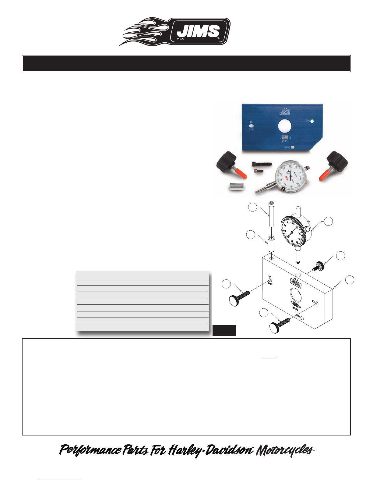
No.785-IS
1
3
3
2
4
5
6
A Division of Thiessen Products, Inc.
IInnssttrruuccttiioonn SShheeeett FFoorr TTooooll ##778855
FFllyywwhheeeell RRuunnoouutt ((TTrruueenneessss)) IInnssppeeccttiioonn GGaauuggee,,
No. 785 - Use on 1970 to present Big Twin Shovel, EVO, and Twin Cam
Check flywheel runout with flywheels in the engine case.
Check the amount of gear lash on gear driven cams used in
some Twin Cam engines. All V-Twin flywheels must be true
when running within an engine.
H-D Service Manual for non -Timken bearing engines 2003
and up lists a service wear limit of .005”. This amount is
checked in a truing stand. JIMS new flywheel gauge has
been designed to check flywheel Runout of the Pinion shaft
(Crankshaft) while assembled in engine case. Engines with
the left side Timken bearing (all JIMS engines have Timken
bearings) show a service wear limit of .003”. When checking flywheels installed in the engine case, the runout will be
greater than when checked on a truing stand. The best way
to use this Runout gauge is with JIMS Tire Rotator Tool No.
936. By using a tire rotator you can relieve more of the
stress being applied to the flywheels than rotating the
engine with the electric starter motor. This tool can also be
used to check cam gear clearance (backlash) see below for
more information.
Rev C
8-13
PARTS AVAILABLE SEPARATELY
No. Qty. Description Part No.
11 INDICATING PLATE 785-1
21 1" DIAL INDICATOR .001 RESOLUTION 940-4
3 2 THUMBSCREW, 1/4-20 X 1-1/2" 1391
41 THUMBSCREW, 10-32 X 1/2" 1392
51 SPACER, 1/4" X 1/2" X 1" 1085
61 SCREW, 1/4-20 X 1-3/4" 1122
7 1 INSTRUCTION SHEET 785-IS
FIG 1
NOTE: PLEASE READ ALL INSTRUCTIONS COMPLETELY BEFORE PERFORMING ANY WORK!
No information in this instruction sheet pertaining to motorcycle repair is represented as foolproof or even altogether safe.
Even something safe, done incorrectly or incompletely can and will backfire. You and only you are responsible for the safety of your repair work and for you understanding the application and use of repair equipment, components, methods
and concepts. Each and every step this tool is designed to do must be carefully and systematically performed safely by
you. All information listed in this instruction sheet has been tested, re-tested and used daily in JIMS
Development Department.
ALWAYS WEAR SAFETY GLASSES OR OTHER FACE AND EYE PROTECTION SUCH AS FULL
FACE SHIELD. JIMS
IS NOT RESPONSIBLE FOR THE QUALITY AND SAFETY OF YOUR WORK.
IF YOU DO NOT KNOW WHAT YOU ARE DOING, DO NOT
®
IS NOT RESPONSIBLE FOR DAMAGE, INJURY, OR YOUR WORK. JIMS
DO IT!
®
Research and
®
555 Dawson Drive, Camarillo, CA 93012 Phone 805-482-6913 • Fax 805-482-9224
11
Page 2

No.785-IS
Rev C
8-13
A Division of Thiessen Products, Inc.
IInnssttrruuccttiioonn SShheeeett FFoorr TTooooll ##778855
Perform all work per H-D® service manual for appropriate year and model for the motorcycle you will be repairing. See JIMS® catalog for a complete listing of all engine and transmission tools.
JIMS Tools recommended for performing this service:
No. 936, JIMS Tire rotator for ease of rotating engine by hand
No. 994 or No. 1285 Cam lock tool, see catalog for year applications.
No. 1283 Cam chain tool see catalog for year applications.
No. 33443-84 Twin Cam oil pimp alignment screw (Qty. 2)
OTHER TOOLS RECOMMENDED FOR USE WITH THIS TOOL:
1 - 3/16" Allen wrench or Allen socket
1- Safety glasses
1 - H-D Service Manual
• Required hand tools needed for the removal of cam cover and cam support.
• Manufacturers specifications for gear driven cams.
Warning: Disconnect the negative ground cable at the battery or Maxi fuse as indicated in service manual.
Note: Follow your service manual for the removal of cam chest components needed to gain access to the end of
Pinion shaft (Crankshaft) for use of this tool.
Assembly of tool for checking Flywheel run out on all Twin cams, EVO, and Shovels 1970 to 1984
1. Apply a small amount of clean oil or lube to the threads of thumbscrew No.1392. Place the mounting end
of indicator No. 940-4 all the way into the bore at the top of indicator plate No.785-1. Position the indicator’s face to be on the same side as the Laser engraving of plate. Just finger tighten the thumbscrew No.1392
so the indicator will not move.
See Fig 1.
2. Apply a small amount of clean oil or lube to the threads of both thumb- screws No.1391. Place the above
assembly up to the cam cover gasket surface of right case. Then, depending on the year of engine you will
be checking, install both thumbscrews No.1391 through the laser marked holes and thread into the case.
The location of mounting screws is determined by the year and model as indicated by the laser marking on
the outside face of the indicator plate. If the application is Twin Cam, install both thumbscrews through these
holes and if the application is EVO or Shovel install both thumbscrews through these holes. See Fig 1.
Caution: As you place indicator plate No.785-1 over Pinion shaft using your finger tip, lift indicator rod up and
over Pinion shaft.
3. On the right side of indicator (about the 2:00 O-clock position) is the face dial lock screw. Loosen it and you
can turn the face to locate the “O” (Zero) at the indicating needle. Retighten the lock screw.
4. Remove the spark plugs and place the transmission in high gear. Position the rear wheel off the ground and
place on stand No. 936. You can rotate the engine while noting the amount of runout as shown on the dial
indicator.
CAUTION: Wear safety glasses over your eyes.
®
See JIMS
555 Dawson Drive, Camarillo, CA 93012 Phone 805-482-6913 • Fax 805-482-9224
catalog for Hundreds of top quality professional tools.
The last tools you will ever need to buy.
22
Page 3
No.785-IS
A Division of Thiessen Products, Inc.
IInnssttrruuccttiioonn SShheeeett FFoorr TTooooll ##778855
.
Note: Please refer to your service manual for the amount of allow-
able flywheel run out. If your flywheels are running out more
than the allowed amount, see JIMS catalog for the tools
required for flywheel removal. If your flywheels are in need of
service, JIMS can rebuild or supply you with a new set of flywheels, contact JIMS at 805-482-6913 or www.jimsusa.com
for application and availability.
Checking Gear drive cams for gear lash
Note: It will be much easier and you will have a better indicator
reading of gear lash if you remove the pushrods or release the
adjustment of all 4 pushrods.
Rev C
8-13
1. If the Allen head screw No.1122 and spacer No.1085 is
mounted to the top left of indicator plate as shown in Fig 1.
remove both and apply a small amount of clean oil or lube to
the threads of screw No.1122. Also remove the indicator by
unscrewing thumbscrew No.1392.
2. Place screw No. 1122 through the mounting hole on the back
side of indicator, followed by spacer No.1085 over the screw.
See Fig 1.
3. With your 3/16” Allen wrench mount this assembly to the top
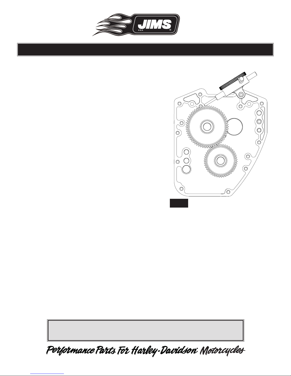
right side cam cover mounting screw hole. Just finger tighten screw no more then 50 in-lbs. At the same
time placing the sharp end (tip removed) of the indicator’s stem on one of the top teeth of cam gear.
See Fig 2.
4. You will need to make sure that the small drive gear mounted to Pinion shaft can not move. You can
gain a more accurate indicator reading by using a wrench (on the bolt holding the gear to cam) to move
the cam gear back and forth as you are checking gear lash.
Note: Follow the manufactures specifications for the correct amount of gear lash required for a quiet valve train.
FIG 2
CAUTION: Wear safety glasses over your eyes.
®
See JIMS
555 Dawson Drive, Camarillo, CA 93012 Phone 805-482-6913 • Fax 805-482-9224
catalog for Hundreds of top quality professional tools.
The last tools you will ever need to buy.
33
 Loading...