

1.Overview
1.1 Features
· LTE & WCDMA & GSM
· WiFi hotspot
· ACC detection for ignition status
· IP65 water proof
· Remote cut-off (petrol/power)
· Multiple alerts
1.2 Specifications
GSM: 850/900/1800/1900 MHz
Frequency
GPS
Location accuracy
WiFi
LED indicator
Battery 450mAh/3.7V
Working
voltage/current
Operating
temperature
Dimension
Weight 105g
1.3 Accessories
12V relay
SOS cable
Power cable
WCDMA: 850/900/1900/2100MHz
(B1/B2/B5/B8)
LTE:B1/B2/B3/B4/B5/B7/B8
Chipset : U-blox 7020
Frequency: GPS L1, 1575.42MHz
<10 meters
2.4 GHz
GPS (blue), GSM(green), power (red)
9-36V
12VDC/76mA(12VDC); 38mA(24VDC)
-20℃~ 70℃
113(L)*51(W)*20(H)mm
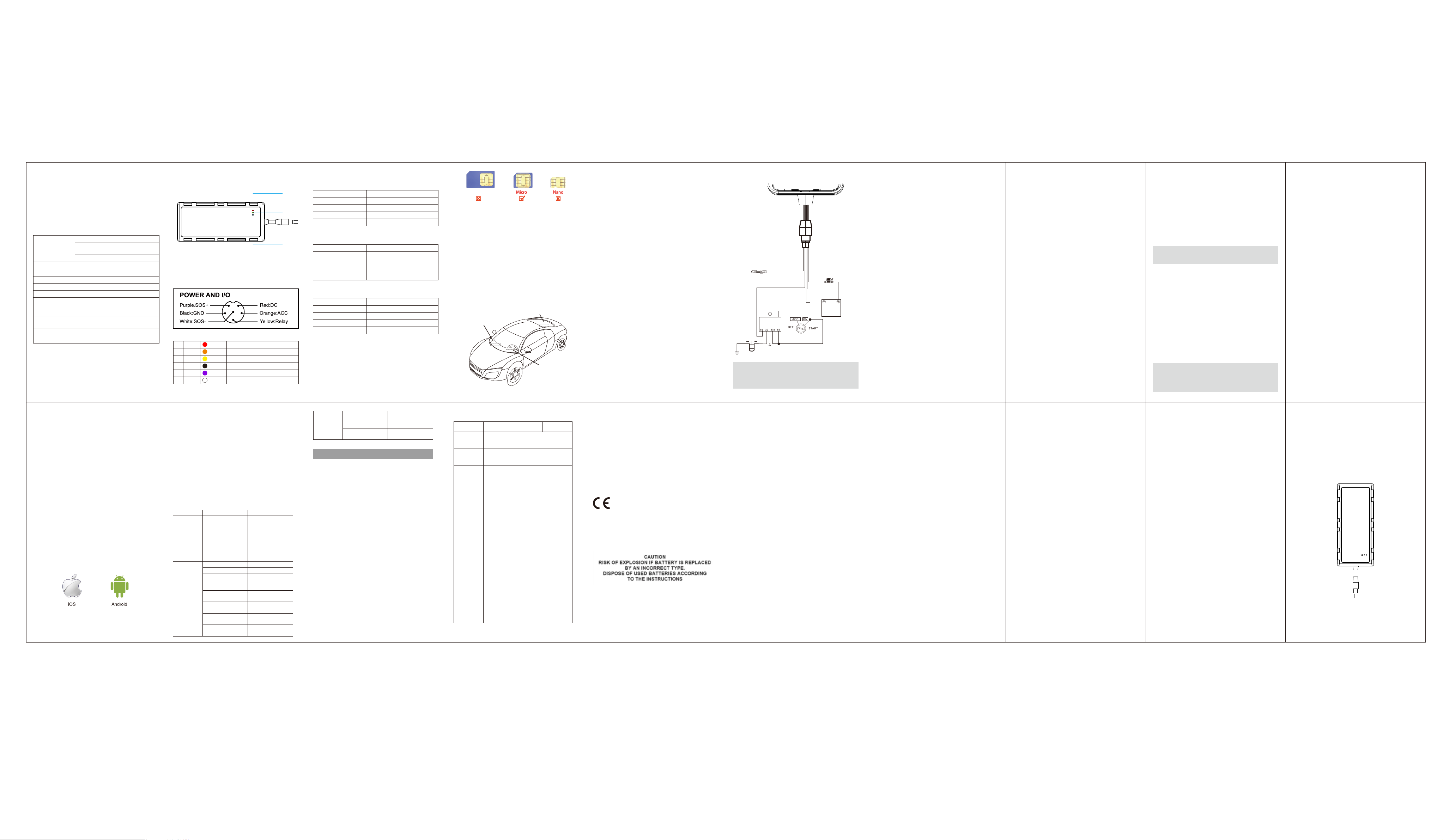
2.Device appearance
3.Wiring Diagram
A1A2Red PW+ Power: 9v~36v
Orange ACC ACC
A3A4Yellow Relay Fuel/Power cut-off
Black GND GND
A5A6Purple SOS + SOS (Positive)
white SOS - SOS (Negative)
POWER
GSM
GPS
4.LED indications
Green LED(GSM indicator)
Status
0.3s ON, 0.3s OFF
1s ON, 3s OFF
0.1s ON, 3s OFF
OFF No GSM or SIM card
Definition
GSM initializing
GSM normal
GPRS online
Red LED(Power indicator)
Status
0.3s ON, 0.3s OFF
1s ON, 3s OFF
Solid Red
OFF
Definition
Low battery
Work normally
Charging
No battery/Malfunction
Blue LED(GPS indicator)
Status
0.3s ON, 0.3s OFF
1s ON, 3s OFF
OFF
Solid ON
Note: LED indicators will be off after 180s when ACC is OFF.
Definition
Searching GPS signal
GPS positioned successfully
GPS sleeps or doesn’t work
Bluetooth configuration
5.Hardware Operation
(1)SIM Card installation
SIM card should have access to GPRS and SMS.
Remove the cover, switch the device to OFF and insert the SIM
card in correct direction.
6.Device Installation
You ne ed to cho ose som ewhe re tha t it wo n’t be found,
bec aus e the whole p oint of fitting covert G PS vehicle
tracker is th e sec recy elem en t.
1. Your d evic e has built-in GSM anten na and G PS a ntenna
D urin g ins tallation, p lease make su re the rece iving side
fa ce is u p ; any high power devices su ch a s reve rsing
ra dar, anti-theft device o r com mun icatio n eq uip me nt
w ou ld affe ct the sign al of th e de vice .
2. All m etallic cas es of th e w indshield will attenu ate the
signa l on th e tra
shield ing e ffects of the me tal co mpou nd o f the c ase.
3. Th e device shou ld be fixed into p osition w ith cable ties
o r wid e do uble-sid e tap e.
der front windshield
Un
ckin g de vice . It’s sim ply d ue to the
Under rear windshield
Device
Device
Device
Around dashboard
- Un der the dash b oard below the fro nt w inds hield ;
- In the parc el shelf in the rear;
- In the fron t bump er (non-material fa ce), m ake sure the
de vice d oe s not get w et;
- Un der the w iper version (n on-metal), m ake sure the
de vice d oe s not get w et;
- No n Covert Installatio n - fix the device on th e dash
bo ard b elow windshield .
.
7.Wiring
1. Th e standa rd vo ltage is 9V-36V, the red w ire is th e
positive, th e bla ck w ire is the negativ e.
2. Co nnect th e bla ck w ire to g round.
Red
Black
Orange
2A FUSE
Storage
batter y
12V or 24V
Pump
SOS
12/24V
Relay
Yellow
Ignition key
NOTE:
Please pay attention to the diagram description,
battery is 9-36V and relay remains 12V / 24V.
8.Operations & Functions
The following operation can be achieved through the terminal
platform or APP provided by the dealer.
8.1 SOS number
(1) Add SOS number via SMS command
Send SMS command: SOS,A,number1,number2,number3 #
(A means add number).
3 SOS numbers can be set. If set successfully, the terminal will
reply “ok”.
e.g. SOS,A,13510****60,135116****6,136126****8#
(set all 3 SOS numbers)
SOS,A, 13510****60# (set the first SOS number)
SOS,A, ,135116****6# (set the second SOS number)
SOS,A, , ,136126****8# (set the third SOS number)
(2) Delete SOS Numbers
Send SMS command: SOS, D,1,2,3#
(D means delete SOS number)
e.g. SOS, D,1# means delete the first number
SOS, D,3# means delete the third number
If you don’t know the sequence number, you can also delete
the number by SMS command like this: SOS,D,number#
e.g. SOS,D,13527852360# means delete this SOS number
directly.
It will reply “OK” if the number is deleted successfully.
(3) Add SOS numbers via platform
You can set SOS number via the platform or APP when device
is online.
8.2 APN setting
To ensure GP RS is activated, please m ake sure A PN is
correct. You can send SM S comm and to set APN :
APN com mand form at: APN ,APN 's Nam e#
E.g: APN ,internet# “( internet” is the AP N of carrier)
The device will reply“ OK ”if setting successfully.
Note: The APN of som e countries have user name and
password, you m ay need to send SM S com mand as
following: APN,APN nam e,user name,passwo rd#
8.3 Server setting
Default platform is w ww.tracksolid.com
To connect to other platform, please send the SMS
com man d to change the DNS or server IP:
DN S : SE RV ER,1,DNS,Por t,0#
E.g: SERV ER,1,gp sde v.tracksolid .com ,21100,0#
IP: SE RV ER,0,IP,Port,0#
I
t will reply “ OK” afte r set su cce ssfu lly.
8.4 Center number
Set center number:
CENTER,A,phone number#
Delete center number:
CENTER,D#
8.5 Upload positioning data regularly
Command
TIMER,T1,T2#
T1: ranges from 0/5~18000 seconds, the upload interval when
ACC ON
T1=0: no data uploaded
T1=5~18000 seconds (Default: T1=10)
T2: ranges from0/5~18000 seconds, the upload interval when
ACC OFF
T2=0: no data uploaded
T2=5~18000 seconds (Default: T2=0)
8.6 Arming time setting
Delay time for device entering arming state after the vehicle
power is off and ACC is in low-level. In the arming state, if the
vehicle vibrates for a few times, it will activate the vibration
alarm system. If the vehicle battery is still not on (ACC is in low
level) after 3 minutes, the device will start vibration alarm.
SMS format:
DEFENSE,TIME#
The time ranges from 1 to 60 minutes, default is 10.
NOTE:
1. Preset SOS numbers before sending SMS alarm messages
and calls.
2. If there is no need for vibration alarm, please send SMS
SENALM,OFF# to close it.
8.7 Wire cut-off alarm
When the e lectricity su pply of de vice is cut off, it will
activate cu t-off alarm. In this ca se, th e de vice w ill sen d
relate d SM S to the S OS num bers and d ial the num bers in
circles. If nob od y answe rs, the call just keeps 3 lo ops at
mo st. At the m eantim e, the device w ill upload pow er cut
off ala rm d ata to the serv er. And it will send:
Cu offt P Alarmow er !<06-1 7 14 :53>,
http ://m aps.go ogle.com/m aps?q =N 22 576 713,E113.9 165
85
NOTE:
The SO S nu mb ers should b e preset, please refer to 8.1.
8.8 Oil cut-off
1. via platform
Sen d oil cut-off co m ma nd o n platform. To m ake sure th e
security of vehicle, tracker can only indicate to cu t off oil
wh en G PS is in valid position status, and the spee d is les s
than 20KM /H o r in sta tic. Pla t
nee ded wh en s end ing oil cut off com man d.
2. Via SM S
Firstly, you sh ould set a cen ter nu mber. Plea se refer to 8 .4.
On ly center n um be r can send the com m and to the device
to cu t off an d restore o il.
The form at is: REL AY,1#
After the com mand is carried o ut, it w ill reply “RELAY:ON”
If the c om m and did n't carry out, it will reply th e reason
abo ut fa il to carry
NOTE:
To ensu re the safe ty of th e driver an d the car, this
com mand is valid only under tw o cond ition s: the G PS is
loca ted; the sp eed is less than 20km/h.
out.
form accou nt pa ssw ord is
8.9 Restoring Oil
1. Via platform
When the alarm is off, send ing recover oil com m and s
ma nually. Dev ice w ill resto re oil su pp lying , and vehicle w ill
wo rk no rm ally again .
Platform acc ount password is n eed ed when se nding oil
cut off com mand.
2. Via SM S
On ly center n um be r can send the com m and to the device
to restore o il.
The form at is: REL AY,0#
After the com mand is carried o ut, it w ill receive ”RELAY:0FF”
8.10 Over Speed Alarm
When the car is m ovin g over a lim ited spe ed in average in
a lim ited tim e perio d, the n the device w ill sen d ov er
spe ed a larm SM S to u ser.
To turn o n the ove r spe ed fu nction, please sen d below
SM S co mma nd:
SPEED,O N,Tim e,Limited spee d,w ay o f alar m#
Tim e range ( Second ): 5-6 00s (default as 10s).
Lim ited s pee d range (km /h): 1-255 , defa ult: 100.
Way of alarm: 0 , GPR S only; 1, SMS +G PR S; de fault : 1.
Examp le: SP EED,ON ,10 ,120,1#
Means wh en th e car is mo ving over 120 km /h in a verage in
10 seconds, the device will se nd o ver s pee d al
arm to user.
8.11 Restore to factory setting
SM S co mma nd fo rm at: to set all param eter "FACTOR Y#"
to de fault facto ry value. Onc e received “FACTORY:OK!”
it succeeds.
8.12 Reboot device
When there is som ething wro ng w ith th e link of GP RS,
e.g., th e param eter settin g of th e de vice is corre ct, bu t you
can't tra ck th e car on th e pla tform . At this m om en t you
can send a co mm and to the d evice to reboo t the d evice.
The form at is: RESET#
After rece iving this c om mand , the d evic e will re boot after
20 seconds
8.13 SOS
In emergent case, press SOS for 3 seconds to activate SOS
alarm. Then the device will send SOS SMS to preset SOS
numbers and dial the numbers in a loop for 3 times till the call
picked up. Alarm message will also be sent to the platform.
8.14 Wi-Fi hotspot
Command: HOTSPOT,S,N,P#
S=ON/OFF Default: OFF (uppercase required)
N=Name, 20 characters, default: last four digits of IMEI
P=Password, minimum eight, default password: 11111111
9.Platform & APP
9.1 Login service platform
Please login the designated service platform to set and
operate the device.
9.2 Download APP
Please download and install the APP in designated website,
APP store or Google Play.
After rece iving this c om mand , the d evic e will re boot after
20 seconds
10. Warning
Battery specified by manufacturer is recommended.
Maintenance or service arising from any other accessories
is not guaranteed.
Manufacturer assumes no responsibility for any damage caused
by non-original accessories.
Do not bend or open the battery.
Do not immerse or burn the battery.
Device dis-assembly is strongly forbidden.
Nonprofessionals’ operation may cause device damage.
11. Troubleshooting
If you are having trouble with your device, try these
troubleshooting procedures before contacting a service
professional.
Problems Causes Solutions
Poor signal
Unable to
boot
Unable to
connect to
the network
The signal waves are
unable to transmit
when use the GPS
tracker in the places
that have poor signal
reception, such as: tall
building around or
basement.
Power switch is offSwitch to ON
Battery low
No SIM card
SIM card inserted
incorrectly
Dirty things exist
above the SIM card
Invalid SIM card
Not in GSM service
area
Poor signal
Using the GPS tracker
in the places that have
good signal condition.
charge
Insert SIM card
Check SIM card
Clean SIM card
Contact network
supplier
Move to service area
Move to area with
strong signal
Contact network
supplier to get GPRS
service
Contact supplier
Fail to locate
SIM has no access to
GPRS
Always reply “Address
inquiry failed”
Warranty instructions and service
1.The warranty is valid only when the warranty card is properly
completed, and upon presentation of the proof of purchase
consisting of original invoice indicating the date of purchase,
model and serial No.of the product. We reserve the right to
refuse warranty if this information has been removed or changed
after the original purchase of the product from the dealer。
2. Our obligations are limited to repair of the defect or replacement
the defective part or at its discretion replacement of the product
itself.
3. Warranty repairs must be carried out by our Authorized Service
Centre. Warranty cover will be void, even if a repair has been
attempted by any unauthorized service centre.
4. Repair or replacement under the terms of this warranty does
not provide right to extension or renewal of the warranty period.
5. The warranty is not applicable to cases other than defects in
material, design and workmanship.
W
Maintenance Record
Date
Product Model
IMEI Number
Fault
Descriptions
Comments
Serviced by
CE Caution:
Use the Product in the environment with the temperature
Between -10℃ and 40℃; Otherwise, it may damage your
product. Products can only be used below 2000m altitude
For the following equipment:
Product Name: 4G Vehicle GPS Tracker
Model: JM-VL01, GV40, VL01
Brand Name: Jimi
Shenzhen Jimi IOT Co., Ltd
E-mail: gaoxingxin@concox.cn
hereby declares that this [Name: 4G Vehicle GPS Tracker,
Model: JM-VL01, GV40, VL01] is in compliance with the
essential requirements and other relevant provisions of
Directive 2014/53/EU.
The equipment was passed. The test was performed according
to the following European standards:
The full text of the EU declaration of conformity is available at
the internet address:
https://www.jimilab.com/JM-VL01-CE-DoC.pdf
The product shall only be connected to a USB interface of
version USB2.0 and that the connection to a power USB is
allowed.
This product is intended for sale and application in a business
environment.
RED Article 10 2
-This product can be used across EU member states
RED Article 10 10
-The product is class 1 product, No restrictions
The RF distance between body and product is 5mm
GSM900: Tx: 880-915MHz, Rx: 925-960MHz
DCS1800: Tx: 1710-1785MHz, Rx: 1805-1880MHz
RF Output Power: GSM900: 31.30dBm, GSM1800: 25.39dBm
EDGE900: 30.30dBm, EDGE1800: 25.75dBm
WCDMA Band 1: Tx: 1920-1980MHz, Rx: 2110-2170MHz
WCDMA Band 8: Tx: 880-915MHz, Rx: 925-960MHz
WCDMA Band 1: 22.86dBm, WCDMA Band 8: 22.37dBm
FDD-LTE Band 1: Tx: 1920-1980MHz, Rx: 2110-2170MHz
FDD-LTE Band 3: Tx: 1710-1785MHz, Rx: 1805-1880MHz
FDD-LTE Band 7: Tx: 2500-2570MHz, Rx: 2620-2690MHz
FDD-LTE Band 8: Tx: 880-915MHz, Rx: 925-960MHz
FDD-LTE Band 1: 23.50dBm, FDD-LTE Band 3: 22.98dBm,
FDD-LTE Band 7: 24.11dBm, FDD-LTE Band 8: 22.56dBm
Wi-Fi:
2412-2472MHz for 802.11b/g/n(HT20)
2422-2462MHz for 802.11n(HT40)
14.16dBm (EIRP)
GPS
Frequency Range: 1575.42MHz receiver
FCC RF Exposure Information and Statement
This device meets the government's requirements for
exposure to radio waves. The guidelines are based on
standards that were developed by independent scientific
organizations through periodic and thorough evaluation of
scientific studies. The standards include a substantial safety
margin designed to assure the safety of all persons regardless
of age or health. The SAR limit of USA (FCC) is 1.6 W/kg
averaged. Device: 4G Vehicle GPS Tracker
(FCC ID: 2AMLF-JM-VL01) has also been tested against this
SAR limit. SAR information on this and other pad can be
viewed on‐line at http://www.fcc.gov/oet/ea/fccid/. Please
use the device FCC ID number for search. This device was
tested simulation typical 5mm body. To maintain compliance
with FCC RF exposure requirements, use accessories should
maintain a separation distance between the user's bodies
mentioned above, the use of belt clips, holsters and similar
accessories should not contain metallic components in its
assembly, the use of accessories that do not satisfy these
requirements may not comply with FCC RF exposure
requirements, and should be avoided.
FCC Warning
This device complies with Part 15 of the FCC Rules. Operation
is subject to the following two conditions:
(1) This device may not cause harmful interference, and (2) this
device must accept any interference received, including
interference that may cause undesired operation.
NOTE 1: This equipment has been tested and found to comply
with the limits for a Class B digital device, pursuant to part 15
of the FCC Rules. These limits are designed to provide
reasonable protection against harmful interference in a
residential installation. This equipment generates, uses and can
radiate radio frequency energy and, if not installed and used in
accordance with the instructions, may cause harmful
interference to radio communications. However, there is no
guarantee that interference will not occur in a particular
installation. If this equipment does cause harmful interference
to radio or television reception, which can be determined by
turning the equipment off and on, the user is encouraged to
try to correct the interference by one or more of the following
measures:
- Reorient or relocate the receiving antenna.
- Increase the separation between the equipment and receiver.
-Connect the equipment into an outlet on a circuit different
from that to which the receiver is connected.
-Consult the dealer or an experienced radio/TV technician for
help.
NOTE 2: Any changes or modifications to this unit not expressly
approved by the party responsible for compliance could void
the user's authority to operate the equipment.
4G Vehicle GPS Tracker
User Manual
(Version 1.0)
One side of the device is marked “ THIS SIDE
TOWARDS SKY”, place the unit upside down will
result in connection issues.
Avoid placing the device somewhere that metal will
be covering it up.
 Loading...