

Page 1
Vehicle GPS Tracker JV200
www.jimilab.com
User Manual
Version: J1409-1.0
Page 2

Thanks for purchasing this Jimi JV200. This device will provide you high quality
GPS tracking service based on Jimi’s exceptional technology and standards.
This user manual has been specially designed to guide you through the functions
and features of your JV200.
Please read this manual carefully before using your device to ensure safe and
correct use.
The descriptions of this manual are based on the default setting of JV200.
Tips
Choose a rate plan wisely: Your JV200 can use up Internet bandwidth really
quickly. Before you use your JV200, we strongly recommend that you talk to your
mobile operator about data rates. If you’re on a standard data plan, the costs
could really add up. Switching to a at-rate plan could be a lot cheaper.
Page 3

Popular Uses:
Fleet Management - Track your eet easily. View up to 15,000 units from a single
map.
Investigators and Law Enforcement - Get the real-time location evidence you
need.
Vehicle Owners - Use for vehicle theft and recovery efforts.
Features and Benets:
No Battery Life Concerns - The unit is hardwired to your vehicle’s battery.
10 Second Location Updates - The FASTEST location updates.
Web-Based Tracking - No software to install, view location data from any web
browser.
Track Up to 15,000 Devices on a Single Account - Perfect for eet management.
Extremely Accurate - Utilizes GPS and GSM Cell Towers for super accurate
location data.
Detailed Reporting - View, Save, and Print detailed driving data - up to 90 days
history.
Page 4
Introducing your JV200
Learn about your device’s layout, indications and specications.
1. Inside the Box
Check your product box for the following items:
● Device
● Charging Cable
● User Manual
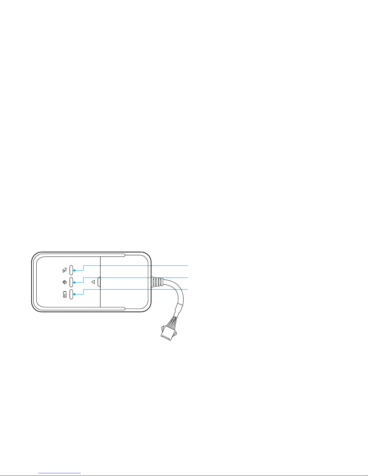
2. JV200 Overview
Power indicator (red)
GSM indicator (green)
GPS indicator (blue)
Page 5

LED Indicators
Power indicator (red) Indication
Flashing Power on
Solid red Not working properly
OFF Power off
GPS indicator (blue) Indication
Quick Flashing (0.1s on, 0.1s off) Searching GPS signal
Solid blue GPS xed
OFF No GPS xed or initializing
GSM indicator (green) Indication
Quick ashing (0.1s on, 0.1s off) GSM initializing
Flashing (0.1s on, 2s off) GSM signal received
Solid green Connected to GPRS network
OFF No GSM signal
LED indicators have two modes:
1. Hidden Mode: All indicators would turn off automatically by pressing LED controller.
2. Continuously Bright Mode: Indicators would never turn off if the device is working.
Page 6

3. Specications
Dimension 86.6(L) x 44(W) x 13.6(H) mm
Weight 50.5g
Operation Temperature -20℃ - 70
℃
Operation Voltage 9-36vDC
Humidity 20% - 80%
GSM Frequencies 850/900/1800/1900 MHz
GPRS Class 12
GPS Sensitivity -159dBm
Acquisition Sensitivity -144dBm
Position Accuracy 10m
TTFF (Open Sky)
Cold Start: <38s
GSM/GPS Antenna
LED Indicator
GSM/GPS Antenna Built-in design
LED Indicator GSM-green, GPS-blue, Power-red
Data Transmit TCP, SMS
Non-movement Detection Movement alarm based on built-in 3D motion sensor
Mileage Report Track by time/distance interval
Page 7
4. Getting Started
Get started by assembling and setting up your device for its rst use.
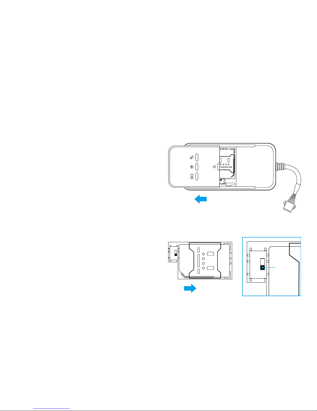
To remove the back cover:
● Firmly hold the device with both
hands and the front panel facing down.
● Push the back cover up with your
thumbs until it disengages from the
device and then slide it up to remove.
4.1 Install SIM card
1. To install the SIM card:
● Locate the SIM card slot, and then
insert the SIM card with its gold
contacts facing down and its cut-off
corner facing out the card slot.
● Slide the SIM card completely into
the slot.
● After SIM card installed, please
switch the power on.
OPEN
OPEN
ON
OFF
power
Page 8

Make sure there is enough credit on the SIM card. If you will be using the
GPRS function, you should pay attention to the current SIM card GPRS charge.
4.2 Charge the device (Covert installation)
Plug the device connector into a charging cable.
The charging cable with 2A FUSE for short-circuit over current protection.
Improperly connecting the charging cable can cause serious damage to the
device. Any damages by misuse are not covered by the warranty.
4.3 Install the device
You need to choose somewhere that it won't be found, because the whole point of
tting covert GPS vehicle tracker is the secrecy element.
1. Your device has built-in GSM antenna and GPS antenna. During installation,
please make sure the receiving side face is up ; any high power devices such
as reversing radar, anti-theft device or communication equipment would
affect the signal of the device.
Page 9
2. All metallic cases of the windshield will attenuate the signal on the tracking
device. It’s simply due to the shielding effects of the metal compound of the
case.
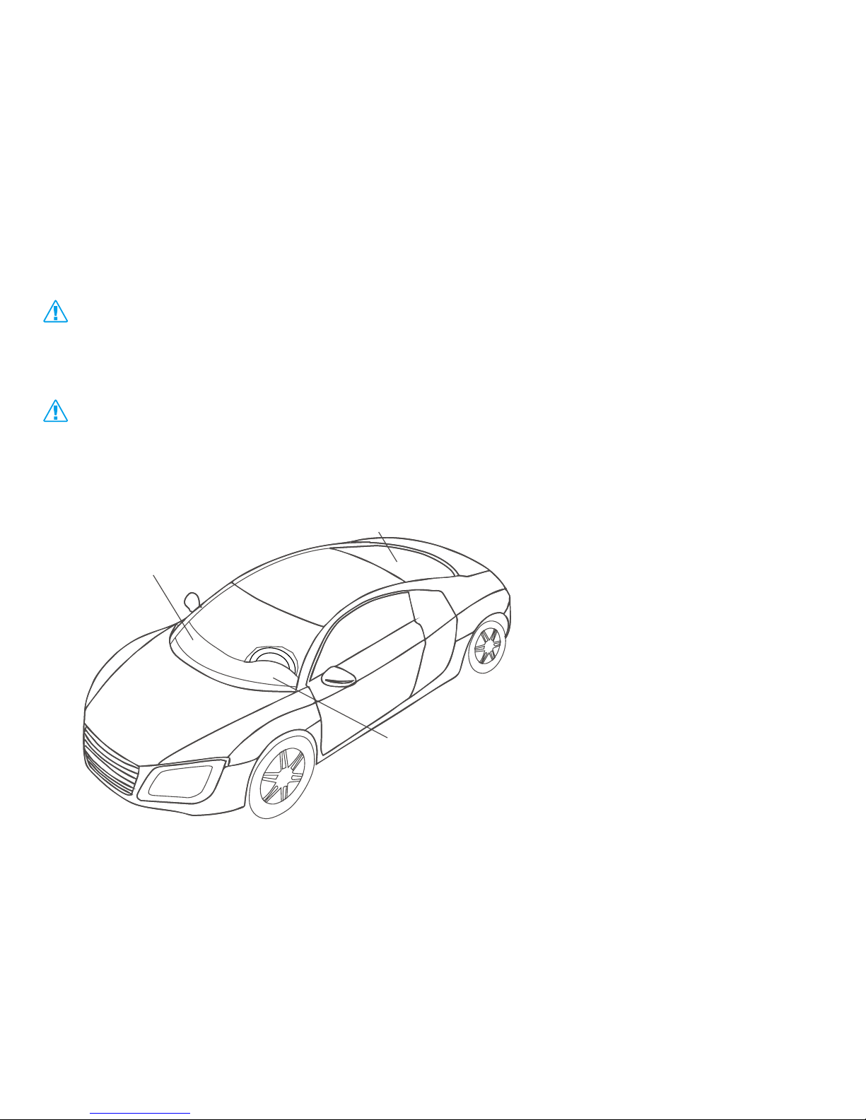
3. The device should be xed into position with cable ties or wide double-side tape.
Installation please refers to below picture.
- Under the dash board below
the front windshield;
- In the parcel shelf in the rear;
- In the front bumper (non-
material face), make sure the
device does not get wet;
- Under the wiper version (non metal), make sure the device
does not get wet;
- Non Covert Installation - x the
device on the dash board
below windshield.
Under front windshield
Under rear windshield
Around dashboard
Page 10
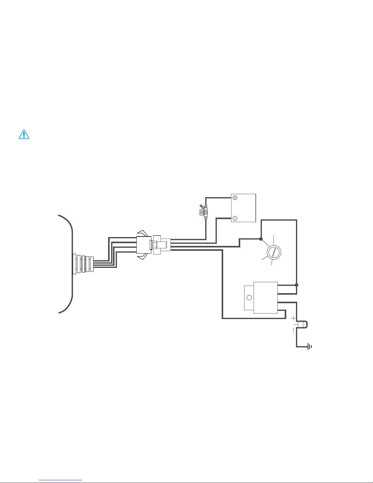
Device Wiring
1 The standard voltage is 9V-36V, the red wire is the positive, the black wire is the
negative.
2. Connect the black wire to ground.
3. Wiring diagram
86 30 87a 85
Red
2A Fuse
Yell ow
ACC
STA RT
Ignition
key
12/24V
Relay
Pump
OFF
ON
Orange
Black
Storage
battery
12V/24V
Page 11

4.5 Power/ACC/Tele-cut off(petrol/electricity) control cable (4 pin)
1. Device standard power supply 9V-36V DC, please use the original factory
supply power cord, red is positive, black is negative. During installation, power
negative please should be independently grounded, do not connect with other
ground wire.
2. The ACC line(orange) connects to ACC switch of the vehicle. Please make sure
to connect the ACC wire; otherwise the device will enter ignition detection status
when disconnect the ACC line. If you don’t need to anti-theft temporarily, just
connect the ACC line to the positive side in parallel.
3. Tele-cutoff(petrol/electricity) control line(yellow) is connected to pin 86 of the
Tele-cutoff (petrol/electricity) relay (equal to the yellow line of the relay socket).
5. Quick Operation Instructions
To properly use the device, common parameters should be set before
initial use. This can be done by using the parameter editor or by sending SMS
commands to the device. (“,”should be English comma and no space
before and after the comma)
Page 12

5.1 Add SOS number
SMS command to the device to add the SOS number.
SOS,A,No.1,No.2,No.3#
“A” means to add new numbers, for example:
SOS,A, 18165542975, 18165542976, 18165542977#
It will reply
“OK!
SOS1: 18165542975 SOS2: 18165542976 SOS3: 18165542977”
after set successfully.
5.2 APN setting
To connect default platform www.jimishare.com, please send the SMS command
below,APN command format:
APN,APN name# or APN,APN name,user name,password#
Example:
APN,CLENTE# or APN,ORANGE,ORANGE,ORANGE#
An automatic reply OK will be sent in one minute if setup is successful.
5.3 Server setting
To connect other platform, please send the SMS commands below:
Page 13

Command format:
SERVER,1,domain,Port,0#
Example:
SERVER,1,www.jimishare.com,8841,0#
It will reply “OK” after set successfully.
5.4 Set the center number
If you want to cut off/restore oil by SMS command, you have to set a center
number rstly. Only the center number can send the cut off/restore oil command
to the device. You can set your own mobile number as center number.
The command for setting center number is:
CENTER,A,mobile number#
For example:
CENT E R , A ,1816 5 542976 #
If set successfully, there is an “OK” reply message.
Only the SOS number can be used to add or delete center number successfully.
There is only one center number can be set.
5.5 GPRS time interval
Page 14

Users can modify GPRS time sending interval by SMS
TIMER,T1,T2#
T1 ranges 5~18000 or 0(seconds), upload interval when ACC ON, 0 means no
upload, default is 10;
T2 ranges 5~18000 or 0(seconds), upload interval when ACC OFF, 0 means no
upload, default is 10;
5.6 Vibration alarm delay time setting
Delay time for device entering vibration alarm state after the vehicle power is off
and ACC is in low-level. In the vibration alarm state, if the vehicle vibrates for a
few times, it will activate the vibration alarm system. If the vehicle battery is still
not on (ACC is in low level) after 3 minutes, the device will start vibration alarm.
SMS format:
DEFENSE,TIME#
The time ranges from 1 to 60 minutes, default is 10.
1. Preset SOS numbers before sending SMS alarm messages and calls.
2. If there is no need for vibration alarm, please SMS SENALM,OFF# to close it.
5.7 Check parameter setting
Page 15

You can check the parameter setting by command:
PARAM#
Example: PARAM#
Information replied:
IMEI: 353419032348877 ---IMEI number of the device;
TIMER: 10,10; ---GPS data uploading Interval;
SENDS:5; --- the GPS working time when ACC is OFF;
SOS:18165542976,,; --- SOS numbers, maximum 3 SOS numbers can be set and
used for alarm and monitoring;
Center Number:18165542976; ---only 1 center number can be set and used for
cutting off /restoring oil command;
Sensoralm: 10,5,1,180; --- detect 5 vibrations in 10s; the alarm delay is 180s;
Defense time: 10; --- the vibration alarm delay is 10 minutes;
TimeZone:E,8,0; --- time zone info.
The replied information contains IMEI number, GPS data uploading Interval, GPS
working time, SOS number, center number, sensor time interval, vibration alarm
delay and time zone info.
5.8 Check GPRS parameters
SMS command format:
Page 16

GPRSSET#
Example:GPRSSET#
Reply message:
GPRS:ON //GPRS on/off status//
Currently use APN:CMNET,user,password; //APN setting information//
Server:1,www.gpsluckly.com,88,0; //platform information//
URL:http://maps.google.com/maps?q=; //preset web link setting information //
6. Operation of device
6.1 Power on/ Power off
Power on: Once insert a valid SIM card and connect all the wires, turn on the
device, then Power LED will ash rst, during signal searching process, GSM and
GPS LED will ash. Once GPS LED keeps slow ashing, it means the device has
been located and it starts to work.
Power off: Just turn off the power switch.
The device will begin to upload positioning data to server once inserting a valid
SIM card and power on. During the working time, it can upload data to server
every 10 seconds.
To power on / power off, please remove the back cover rst, refer to 4. Getting Started.
Page 17

6.2 Check location
1. Via SMS
1.1 SMS “WHERE#” to the SIM number of device. The device will send a
location message automatically. You can get the coordinates. If the device does
not search any information of location, it will send “No data” to the cell phone.
Example:
Current position!
Lat:N22.577156,Lon:E113.916748,Course:131.99,Speed:0.00Km/h,Date
Time:2013-10-08 17:35:32
1.2 SMS “URL#” to the SIM number of device. The device will send a location
Google Map link. If the device does not search any information of location, it
will send “No data” to the cell phone.
Example:
<10-08 17:36>http://maps.google.com/maps?q=N22.577156,E113.916748
2. Via platform
Go to the platform website offered by dealers to check your vehicle location.
6.3 Wire cut-off alarm
When the electricity supply of device is cut off, it will activate cut-off alarm. In
Page 18

this case, the device will send related SMS to the specic numbers and dial the
numbers in circles. If nobody answers, the call just keeps 3 loops at most. At the
meantime, the device will upload SOS alarm data to the server. And it will send:
Cut Power! <Date Time:13-06-17 14:53:06>, http://maps.google.com/
maps?q=N22576713,E113.916585
The specic numbers should be preset, please refer to 5.1
6.4 Low battery alarm
When the device is only working with battery, once the internal voltage of battery
is less than 3.7V, device will send low battery alarm SMS to specic number and
alarm on platform.
Low battery alarm SMS content example:“Attention!!!Battery is too low, please
charge.” Which means the battery is too low, inform user charging it in time.
The specic numbers should be preset, please refer to 5.1.
6.5 Vibration alarm
The vibration alarm function is off by default. To activate this function, please send
the following command:
Page 19

SENALM, ON#
The alarm will be sent to both the service platform and SOS numbers.
When vehicle power is off, ACC status is low, and if the lead time of low ACC is
more than 10 minutes (settable), device will activate security alarm.
When the security alarm is on, once the vehicle vibrates for several times, the
alarm will be activated; in the next 3 minutes, if vehicle power is still off (ACC
status is low), device will activate vibration alarm.
The device will then send an alarm message to the platform, also another SMS
vibration alarm message to the preset SOS number.
Example:
Sensor Alarm! <11-23 14:53>, http://maps.google.com/
maps?q=N22576713,E113.916585
1. The SOS numbers should be preset.
2. Send “SENALM, OFF#” to turn off the vibration alarm if don’t need.
Page 20

6.6 Oil cut-off
1. via platform
Send oil cut-off command on platform. To make sure the security of vehicle,
tracker can only indicate to cut off oil when GPS is in valid position status, and
the speed is less than 20KM/H or in static. Platform account password is needed
when sending oil cut off command.
2. Via SMS
Firstly, you should set a center number. Please refer to 5.4.
Only center number can send the command to the device to cut off and restore oil.
The format is: RELAY,1#
After the command is carried out, it will reply “Cut off the fuel supply: Success!
Speed:0 Km/h”. If the command didn't carry out, it will reply the reason about fail
to carry out.
To ensure the safety of the driver and the car, this command is valid only under
two conditions: the GPS is located; the speed is less than 20km/h
6.7 Restoring Oil
1. Via platform
Page 21

When the alarm is off, sending recover oil commands manually. Device will restore
oil supplying, and vehicle will work normally again.
Platform account password is needed when sending oil cut off command.
2. Via SMS
Only center number can send the command to the device to restore oil.
The format is: RELAY,0#
After the command is carried out, it will receive “Restore fuel supply: Success!”
6.8 Over Speed Alarm
When the car is moving over a limited speed in average in a limited time period,
then the device will send over speed alarm SMS to user.
To turn on the over speed function, please send below SMS command:
SPEED,ON,Time,Limited speed,way of alarm#
Time range(Second): 5-600s (default as 20s).
Limited speed range(km/h): 1-255, default:120.
Way of alarm: 0, GPRS only; 1, SMS+GPRS; default:1.
Exam p le: SPEED,O N,10,120,1#
Means when the car is moving over 120km/h in average in 10 seconds, the device
will send over speed alarm to user.
Page 22

6.9 Restore to factory setting
SMS command format: “FACTORY#” to set all parameter to default factory value.
Once received “OK”, it succeeds.
6.10 Reboot device
When there is something wrong with the link of GPRS, e.g., the parameter setting
of the device is correct, but you can't track the car on the platform. At this moment
you can send a command to the device to reboot the device.
The format is: RESET#
After receiving this command, the device will reboot after 1mins.
7. Register and log onto GPS tracking platform: www.jimishare.com
Account: IMEI Number
The function on the GPS platform can be realized as follows:
● Real-time Tracking
● Report and Statistics
● Online Conguration
8. Troubleshooting
If you are having trouble with your device, try these troubleshooting procedures
Page 23
before contacting a service professional.
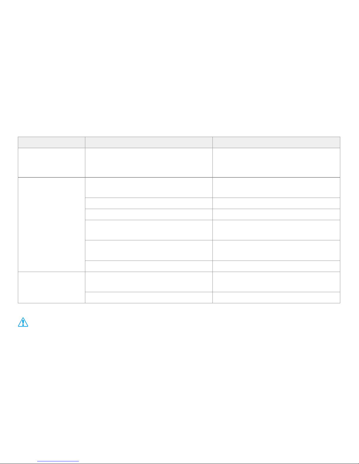
Problems Causes Solutions
Red LED does
not work when
power connected
The fuse blows Replace the fuse
Fail to connect
network
Wrong installation of SIM card
Check SIM card installation
(►4.1 Install SIM card)
Filth on the SIM card iron surface. Clean it
Useless SIM Contact internet service provider
Improper installation
Check installation of device
(►4.3 Install the device)
Beyond GSM service area
Use it in effective GSM service
offer area
Bad signal Try again in a better signal area
Fail to charge
The voltage is unsuitable
Connect with power with suitable
voltage
Improper connection Check connection with charger
Safety Precautions
Handle and dispose of batteries and chargers with care
Page 24

Use only JIMI-approved accessories specially designed for your device.
Incompatible accessories can cause serious injuries or damage to your device.
Never place batteries or devices on or in heating devices, such as microwave
ovens, stoves, or radiators. Batteries may explore when overheated.
Never crush or puncture the battery. Avoid exposing the battery to high external
pressure, which can lead to an internal short circuit and overheating.
Correct disposal of this product
(Waste Electrical & Electronic Equipment)
(Applicable in the European Union and other European countries with separate
collection systems)
This marking in the battery, manual or packaging indicates that batteries on this
product should not be disposed of with other household waste at the end of their
working life. If batteries are not properly disposed of, these substances can cause
harm to human health or the environment.
To protect the natural resources and to promote material reuse, please separate
batteries from other types of waste and recycle them through your local, free
battery return system.
 Loading...