

Page 1
User Guide DT-210/230 Thermal Receipt Printer
Page 2

Tally Dascom DT-210/230 User Guide V1.3
Important Safety Instructions (English)
Read the following instructions thoroughly before starting up your printer.
• The device and mains-socket must all times be easily accessible.
• Never carry out maintenance or repair work yourself. Always contact a qualified service
technician.
• Keep this user guide in a place which is easily accessible at all times.
• Place the printer on a solid and even base so that it cannot fall.
• Never place the printer in the vicinity of inflammable gas or explosive substances.
• Ensure the printer is connected to a socket with the correct voltage.
• Always disconnect the printer from the power before opening the device to perform
maintenance work or remedy errors.
• Do not expose the printer to high temperatures, direct sunlight or dust.
• Keep all liquids away from the printer.
• Protect the printer from shock, impact and vibration.
• Make sure that both the printer and the computer are switched off before connecting the data
cable.
• The print head will become very hot during printing; avoid contact with the print head after
printing has finished.
• Do not perform any operation or action in any way other than those provided in this manual.
When in doubt, contact your dealer or your customer support.
I
Page 3

Tally Dascom DT-210/230 User Guide V1.3
About This Manual
This manual provides information to operators of the DT-210/230 to describe basic operations to enable safe
and correct use of the printer.
Symbols Description
The symbols in this manual are identified by their level of importance, as defined below. Read the following
carefully before handling the product.
CAUTION: Provides information that must be observed to prevent damage to the
equipment or loss of date.
NOTE: Advises you of information that is essential to complete a task.
II
Page 4

Tally Dascom DT-210/230 User Guide V1.3
TABLE OF CONTENTS
ABOUT THIS MANUAL .................................................................................................................................. II
1 PRODUCT OVERVIEW ................................................................................................................................ 1
1.1 Features ............................................................................................................................................................... 1
1.2 Unpacking ............................................................................................................................................................ 3
1.3 Product Configurations ........................................................................................................................................ 4
1.4 Part Names and Functions ................................................................................................................................... 5
1.4.1 Power Switch ................................................................................................................................................. 6
1.4.2 Control Panel ................................................................................................................................................. 6
1.4.3 LED Indicators ............................................................................................................................................... 7
2 SETUP ....................................................................................................................................................... 8
2.1 Flow of Setup ....................................................................................................................................................... 8
2.2 Installing the Printer ............................................................................................................................................. 9
2.3 Changing the Paper Width ................................................................................................................................. 10
2.4 Attaching Power ................................................................................................................................................. 11
2.5 Adjusting the Paper Near-end Sensor ................................................................................................................ 12
2.6 Loading Roll Paper .............................................................................................................................................. 13
2.7 Installing Optional Kits ....................................................................................................................................... 15
3 INSTALLING DRIVER .................................................................................................................................. 16
3.1 Installation Driver for Ethernet and Wi-Fi Interface .......................................................................................... 18
3 CONNECTING TO COMPUTER .................................................................................................................... 23
3.1 For USB Interface ............................................................................................................................................... 24
3.2 For Cash Draw Interface ..................................................................................................................................... 24
3.3 For Serial Interface ............................................................................................................................................. 25
3.4 For Parallel Interface
3.5 For Ethernet Interface ........................................................................................................................................ 26
3.6 For W ireless LAN Interface ................................................................................................................................ 30
3.6.1 Get IP Address ............................................................................................................................................. 32
3.6.2 Wlan Setup - AP mode ................................................................................................................................ 35
3.6.3 Wlan Setup - STA mode ................................................................................................................................37
3.6.4 Return to Factory Setting ............................................................................................................................ 38
3.7 Connecting to Bluetooth .................................................................................................................................... 39
3.7.1 Installing Bluetooth Adapter Driver ............................................................................................................ 39
3.7.2 Changing Printer Port .................................................................................................................................. 41
3.7.3 Changing Baud Rate of the Printer .............................................................................................................. 44
4 SETTING/CHECKING MODES ...................................................................................................................... 45
4.1 Self-test Mode .................................................................................................................................................... 45
4.2 Hexadecimal Dumping Mode ..............................................................................................................................47
.......................................................................................................................................... 26
5 SETTING DIP SWITCHES ............................................................................................................................. 48
5.1 Setting Procedure ............................................................................................................................................... 48
5.2 For Serial Interface (RS-232C) ............................................................................................................................ 49
5.3 For Parallel and USB2.0 Interface ....................................................................................................................... 50
5.4 Selecting the Print Density ................................................................................................................................. 51
Page 5

Tally Dascom DT-210/230 User Guide V1.3
5.5 Auto Cutter Enable/Disable Selection ................................................................................................................ 51
6 TROUBLESHOOTING .................................................................................................................................. 52
6.1 Error Status ........................................................................................................................................................ 52
6.2 Removing Jammed Paper ................................................................................................................................... 53
6.3 Cleaning Thermal Head ...................................................................................................................................... 54
7 SPECIFICATIONS ........................................................................................................................................ 55
7.1 Printer Specification ........................................................................................................................................... 55
7.2 External Dimension and Mass .............................................................................................................................57
7.3 Interfaces ........................................................................................................................................................... 58
7.3.1 USB interface ............................................................................................................................................... 58
7.3.2 Cash Drawer interface ................................................................................................................................. 58
7.3.3 Serial interface ............................................................................................................................................ 59
7.3.4 Parallel interface ......................................................................................................................................... 59
7.3.5 Ethernet interface ....................................................................................................................................... 61
7.3.6 Wi-Fi interface ............................................................................................................................................ 61
7.4 Power Adapter ................................................................................................................................................... 61
7.5 Paper Specification ............................................................................................................................................ 62
7.5.1 Printable Area ............................................................................................................................................. 62
7.5.2 Printing and Cutting Positions ..................................................................................................................... 64
8 CHARACTER CODE PAGES .......................................................................................................................... 65
8.1 Common to All Pages (International Character Set: USA) .................................................................................. 65
8.2 International Character Sets .............................................................................................................................. 66
8.3 [User-defined page] ........................................................................................................................................... 67
8.4 [PC437: USA, Standard Europe] ......................................................................................................................... 68
8.5 [PC850: Multilingual] ......................................................................................................................................... 69
8.6 [PC852: Latin2]
8.7 [PC858: Euro] ..................................................................................................................................................... 71
8.8 [PC860: Portuguese] ...........................................................................................................................................72
8.9 [PC863: Canadian-French] ................................................................................................................................. 73
8.10 [PC865: Nordic] .................................................................................................................................................74
8.11 [PC866: Cyrillic #2] ........................................................................................................................................... 75
8.12 [KU42: Thai] ......................................................................................................................................................76
8.13 [TIS11: Thai] ..................................................................................................................................................... 77
8.14 [TIS18: Thai] ..................................................................................................................................................... 78
8.15 [PC720: Arabic] ................................................................................................................................................. 79
8.16 [PC864: Arabic] ................................................................................................................................................ 80
8.17 [WPC1256: Arabic] ........................................................................................................................................... 81
9 PRINTING CONTROL COMMAND SETS ........................................................................................................ 82
....................................................................................................................................................70
FCC STATEMENT ........................................................................................................................................... 86
DASCOM REPRESENTATIVES ......................................................................................................................... 87
Page 6

Tally Dascom DT-210/230 User Guide V1.3
1 PRODUCT OVERVIEW
Tally Dascom’s DT-210/230 offers high-speed label printing for a wide range of terminal equipment
including data, POS, and kitchen terminals. With extensive features, they can be used in a wide range
of applications such as food service, retail and grocery.
With an internal memory large enough to store logos, footers, custom fonts, keywords and
downloading custom applications, this unit has it all. The DT-210/230 can be desktop or
wall-mounted and comes standard with USB interface, RS-232 serial, Centronics parallel, Ethernet,
Wi-Fi or Bluetooth interfaces. Printer drivers included are: Windows XP (32 and 64 bit), Windows
Vista (32 and 64 bit), Java POS, OPOS, and Linux.
1.1 Features
Printing
• High speed printing (260 mm/s maximum).
• Versatile roll capacity with ability to use 80mm, and 58mm wide paper rolls.
• Can use paper roll with a maximum of 83mm diameter.
• 2-color printing is supported (When specified paper is used).
• Equipped with a fast and quiet cutter.
Handling
• Compact design, can be installed anywhere.
• Drop-in paper roll mechanism facilitating easy paper handling and head cleaning.
• Drip-proof design.
Software
• Command protocol is based on the ESC/POS Proprietary Command System.
• OPOS ADK, OPOS ADK for .NET, JavaPOS ADK, Linux, and Windows printer drivers are available.
• Barcode and 2D barcode printing supported.
• Various layouts are possible by using page mode.
• Buzzer reminder after each printout.
• Paper-saving function is supported.
1
Page 7

Tally Dascom DT-210/230 User Guide V1.3
• The DT-210/230 is ENERGY STAR qualified. (Some configurations may be exempted, depending on their
components.)
Others
• Wide range of connectivity. The USB interface is standard interface. Serial/parallel/Ethernet/ Wi-Fi/
Bluetooth are optional interfaces. Various interface choices suit all needs.
• Built-in USB interface is also available for all interface models.
• The DT-210/230 Software & Documents Disc (drivers, utility, and manuals).
• Printer status and errors indicated by 3 LEDs and a buzzer.
2
Page 8
Tally Dascom DT-210/230 User Guide V1.3
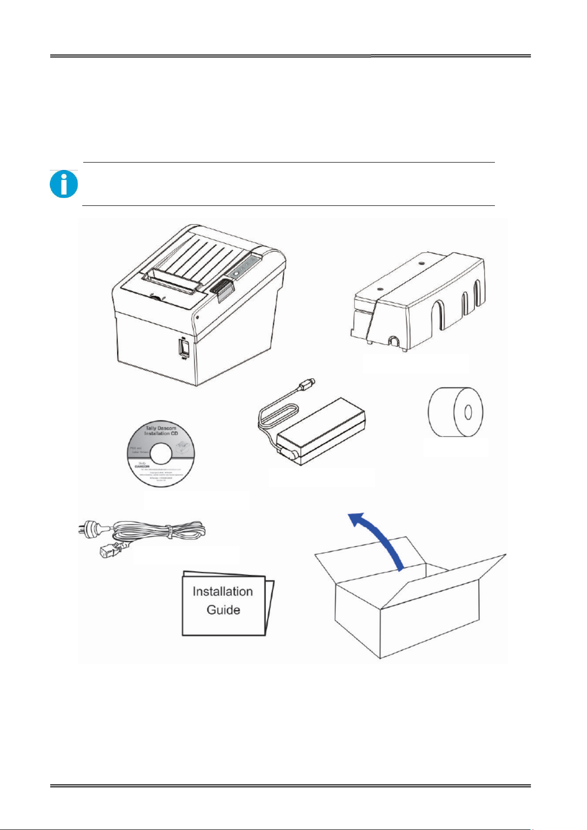
Interface Cable Cover
Power Cord
CD
Roll Paper
Power Adaptor
1.2 Unpacking
Open the packaging, lift the printer out of the cardboard box and remove the remaining packaging
material. Check the printer for any visible transport damage and missing items. If you find any
transport damage or any accessories are missing, please contact your dealer for assistance.
Please keep the packaging material for future transportation.
The shipping list varies with different customized order requirements.
3
Page 9
Tally Dascom DT-210/230 User Guide V1.3
Shipping List
Items QTY. Remarks
Printer 1 unit
Interface Cable Cover 1 piece
Power Adapter 1 piece
Power Cord 1 piece
Roll Paper -Test 1 piece
Graphic Installation Guide 1 piece
CD 1 piece
including user guide, graphic installation
guide, Driver and demo tool
1.3 Product Configurations
There are two models in this series.
• DM-310: without auto cutter
• DM-330: with auto cutter
Interface Types
• USB model
• Serial UB + built-in USB interface model
• Parallel UB + built-in USB interface model
• Ethernet UB
• Wireless LAN UB
• Bluetooth UB
4
Page 10
Tally Dascom DT-210/230 User Guide V1.3
Model
Power
Adapter
Interfaces
100-240 USB Cashbox PAR SER ETH Wi-Fi Fiscal EN/UK/EU Cutter
Power
Cord
Paper Cut Sensor
Tear
Bar
Black
Mark
DT-210
DT-230
√ √ √
√ √ √
O O O O O
O O O O O
√
N
√ √ √
Remarks: “√” indicates standard configuration, “O” indicates optional configuration.
PAR=Parallel interface; SER= Serial interface; ETH=Ethernet interface.
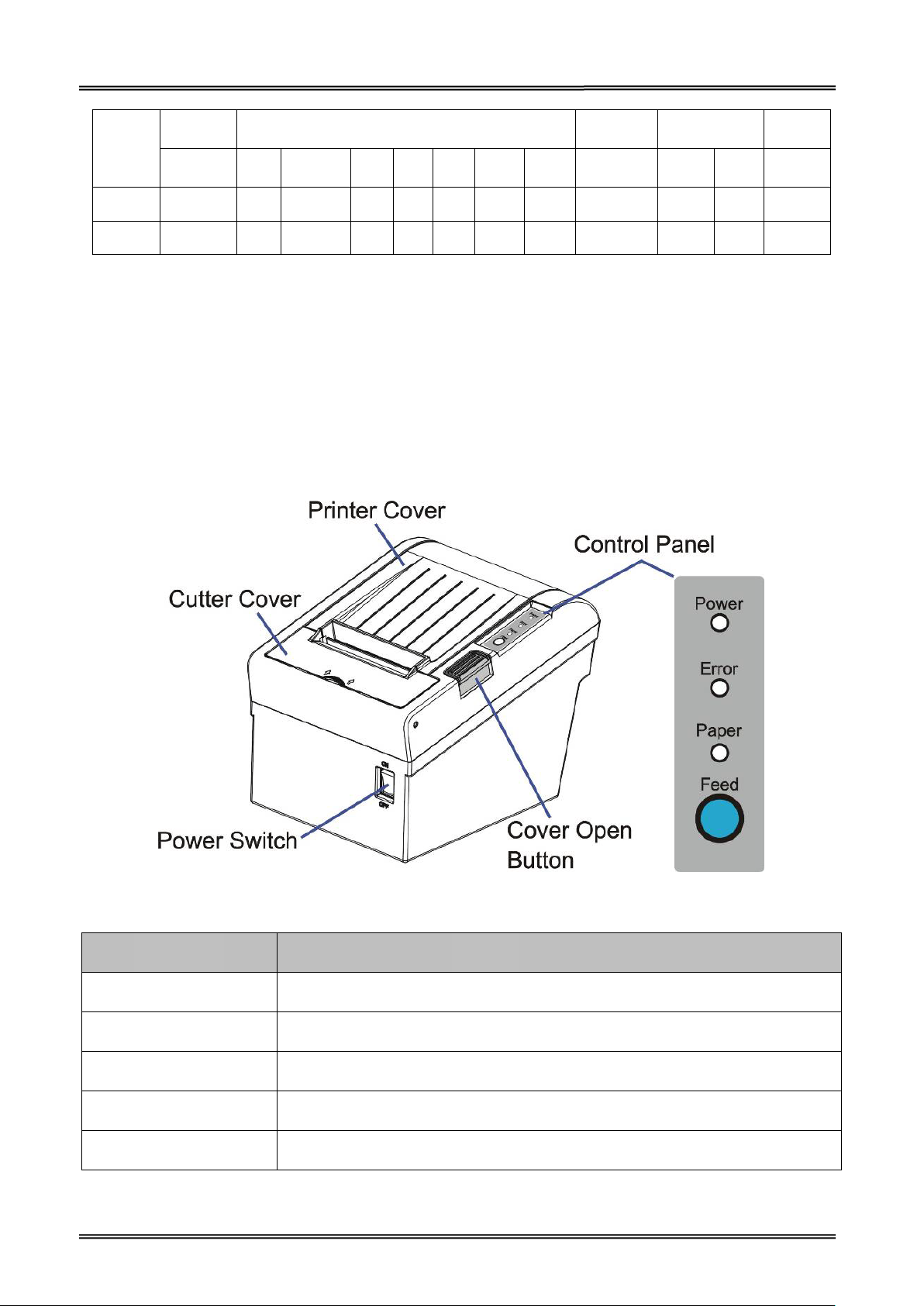
1.4 Part Names and Functions
Printer components and functions are shown as below:
√
O
O
Component Function
Printer Cover Open the cover when loading roll paper.
Control Panel Shows printer status.
Power Switch To power printer ON or OFF.
Cutter Cover To protect the auto-cutter and to clear paper jam at cutter.
Cover Open Button Press down to open the Printer Cover
5
Page 11
Tally Dascom DT-210/230 User Guide V1.3
1.4.1 Power Switch
Turn the printer on or off. The marks on the switch: (O: OFF / | : ON)
Before turning on the printer, be sure to check that the AC adapter is connected to
the power supply.
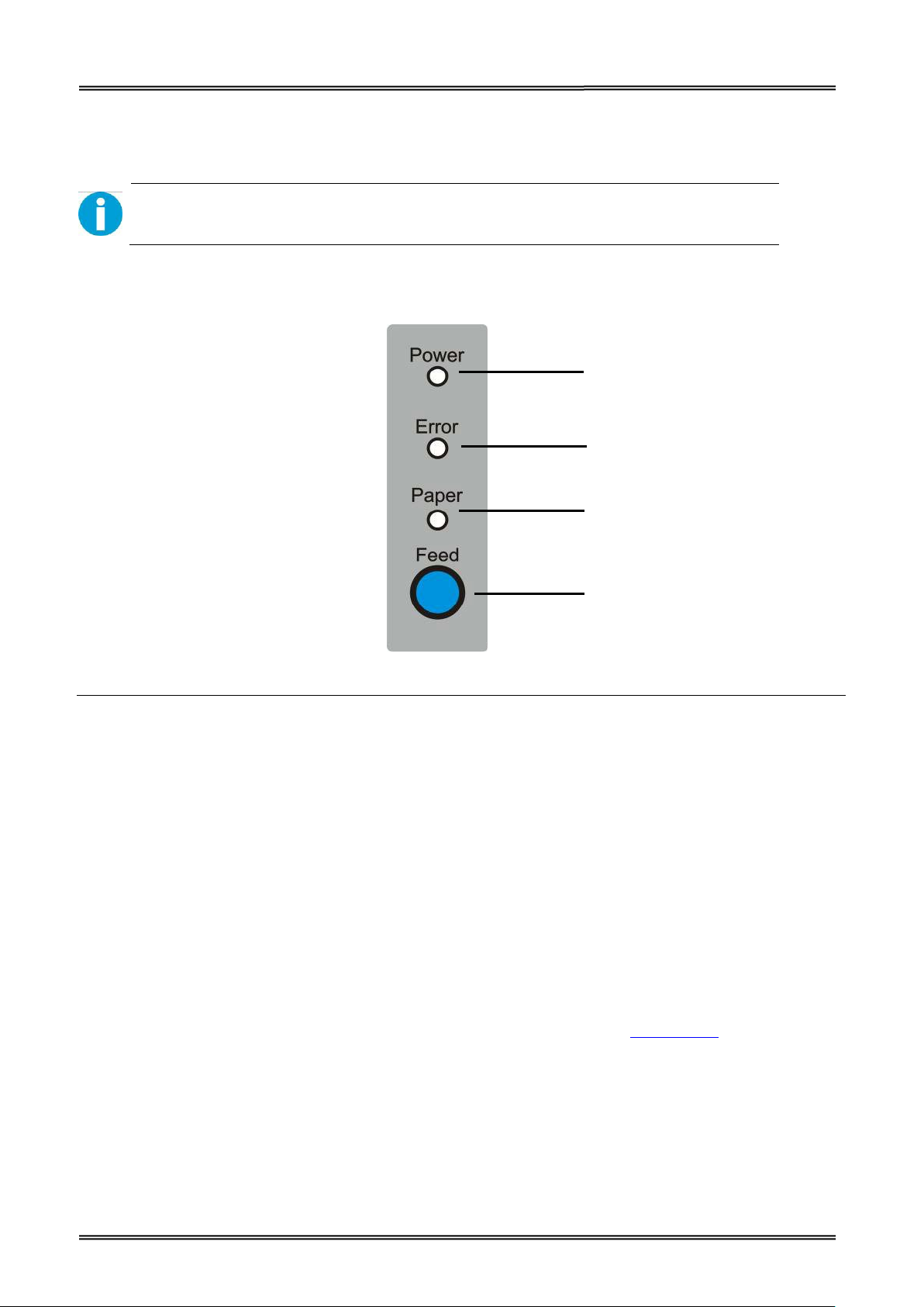
1.4.2 Control Panel
Power LED
Error LED
Paper LED
Feed key
LEDs
Power LED (green)
• Lights when the power supply is on.
• Goes out when the power supply is turned off.
Error LED
Lights or flashes when the printer is offline.
• Lights after the power is turned on or after a reset (offline). Automatically goes out after a while
to indicate that the printer is ready.
• Lights when the end of the roll paper is detected, and when printing has stopped (offline). If this
happens, replace the roll paper.
• Flashes when an error occurs. (For details about the flash code, see “Error Status” on page 52.)
• Goes out during regular operation (online).
Paper LED
• Lights when there is no more roll paper or there is little remaining.
• Off when there is a sufficient amount of roll paper remaining.
• Flashed when a self-test is in progress.
6
Page 12

Tally Dascom DT-210/230 User Guide V1.3
Short beep for twice and long beep for
Feed Key
Pressing this key once feeds the roll paper by one line. Holding this button down feeds the roll paper
continuously.
1.4.3 LED Indicators
Description POWER ERROR PAPER BEEPER
Printer Cover is open On On On
once
Roll paper is sufficient On Off Off No beep
Roll paper end On On On Short beep for three times
Roll paper near end On Off On No beep
7
Page 13

Tally Dascom DT-210/230 User Guide V1.3
9. Connecting the Cash Drawer (page 24)
7. Installing Driver (page 16)
6. Printing Self-test (page45)
2. Changing the Paper Width (page 10)
1. Installing the Printer (page 9 )
2 SETUP
This chapter describes the setup and installation of the product and peripherals.
2.1 Flow of Setup
This chapter consists of the following sections along with the setup flow of the product and
peripherals.
3. Setting the Dip Switches (page 48)
4. Attaching Power (page 11)
5. Adjusting the Paper Near-End Sensor (page 12)
8. Connecting the Printer to the Host Computer (page 23)
8
Page 14

Tally Dascom DT-210/230 User Guide V1.3
Be sure to attach the connector cover when you install the printer on a wall using
2.2 Installing the Printer
You can install this printer horizontally. With an optional mounting plate (P/N: 99501), you can also
attach the printer to a wall.
Important Notes on Horizontal Installation:
• The printer must be installed horizontally on a flat surface (not tilted).
• Do not place the printer in dusty locations.
• Do not knock or strike the printer. This may cause defective print.
• Do not catch cables or place foreign matter under the printer.
Important Notes on Horizontal Installation:
You need to perform the follow tasks to install the printer on a wall. For more details, turn to
Mounting Plate installation part on page 16.
• Installing the roll-paper stoppers.
• Changing the location of the roll paper near-end sensor.
• Attaching the connector cover.
• Attaching the wall mounting plate (P/N: 99501).
the wall mounting plate.
9
Page 15

Tally Dascom DT-210/230 User Guide V1.3
2.3 Changing the Paper Width
The printer is initially set to print on 80 mm width paper and you can change the printer to print on
58 mm width paper by installing the roll paper guide and changing the paper width setting with
customized value.
Follow the steps below to install the roll paper guide.
1. Open the roll paper cover.
2. Hold the paper separator and carefully pull it out in the direction of arrow.
3. Move paper separator from right side to the specified position near the middle of paper h ol de r,
and carefully insert it into the specified position.
10
Page 16
Tally Dascom DT-210/230 User Guide V1.3
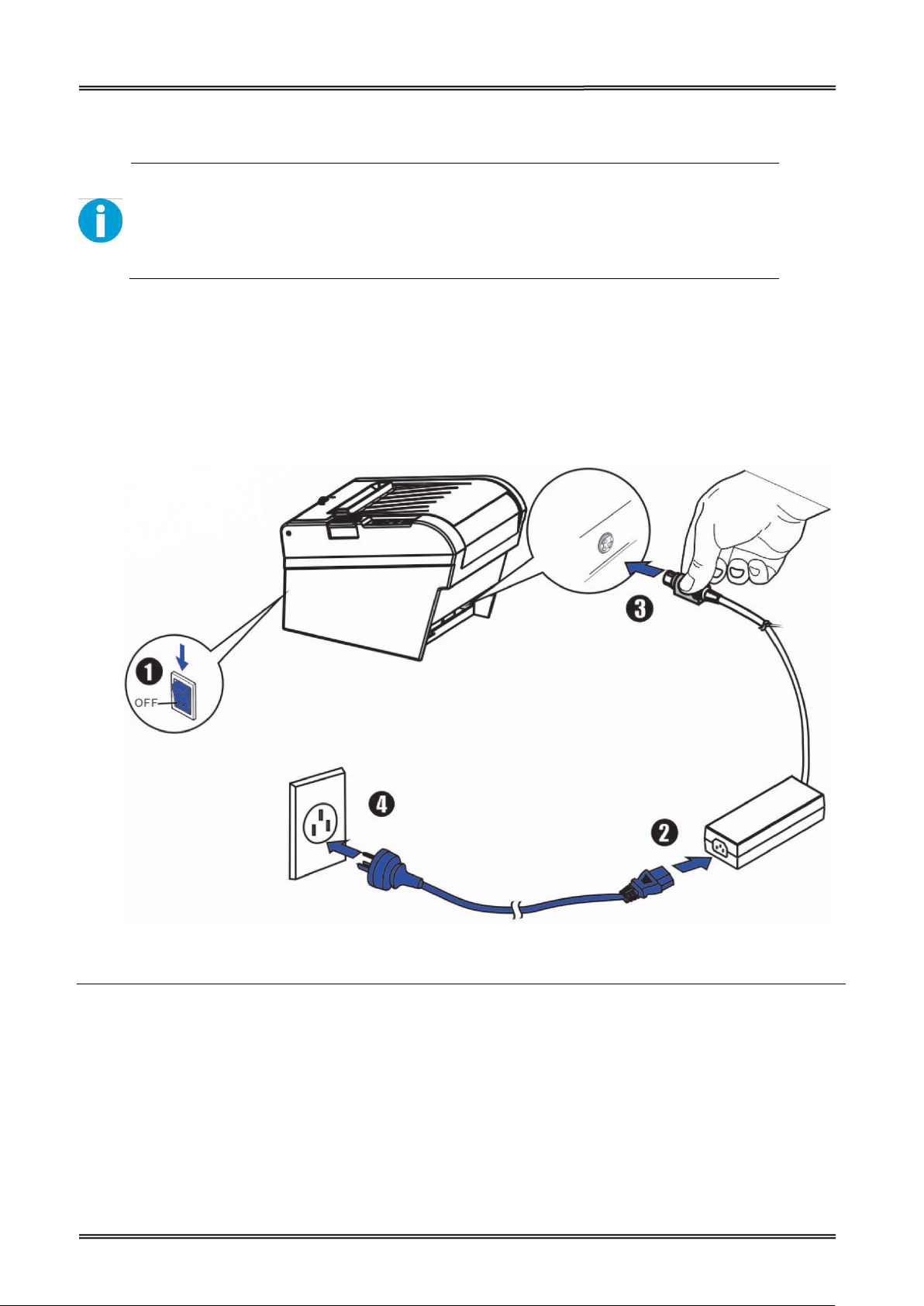
Before you connect the power adapter to the power socket check if the voltage is
2.4 Attaching Power
Checking the voltage of the power adapter
correct. If you connect the power adapter to power with incorrect voltage this may
result in electrical damage to adapter and printer.
1. Make sure the printer and the computer are powered off.
2. Connect the power cord to the power adapter.
3. Connect the power adapter to the power supply interface at the rear of the printer.
4. Ensure the power cord is securely connected. Connect the power cord plug to a
mains socket on the wall.
Power on and power off
• Press the power switch to the “I” position to turn on the printer.
Upon power-on, the Power LED indicator light up.
• Press the power switch to the “O” position to turn off the printer.
11
Page 17

Tally Dascom DT-210/230 User Guide V1.3
2.5 Adjusting the Paper Near-end Sensor
Below are two situations where a paper near-end sensor adjustment is required.
• To adjust the detection position to suit the diameter of the roll paper core used.
• To adjust the detection position of remaining amount of paper.
CAUTION!
Since roll paper cores vary slightly in shape, depending on paper roll design and
manufacturing tolerances, it is impossible to detect the remaining paper exactly.
Follow the steps below to adjust the roll paper near-end detector.
1. Open the roll paper cover, and remove the roll paper.
2. You will see a black lever inside as shown below.
3. Adjust the lever according to your need.
Adjustments position Remaining amount of paper (outer diameter: mm)
1 (Minimum) Approx. 26 {1.02”}
2 Approx. 27 {1.06”}
3 Approx. 28 {1.10”}
4 Approx. 30 {1.18”}
5 Approx. 32 {1.26”}
6 (Maximum) Approx. 33 {1.30”}
12
Page 18

Tally Dascom DT-210/230 User Guide V1.3
2.6 Loading Roll Paper
WARNING!
When opening the cover, take care not to touch the print head or cutter blade.
Otherwise, burning or injury of hand may result.
1. Press the cover open button to open the cover.
2. Remove the used roll paper core, if any.
3. Insert the paper roll with its print area facing down as shown in the figure.
13
Page 19

Tally Dascom DT-210/230 User Guide V1.3
4. Install the media in the correct direction.
5. Pull out some roll paper, and close the cover.
6. Tear off the paper with the manual cutter till you hear a click sound.
14
Page 20

Tally Dascom DT-210/230 User Guide V1.3
2.7 Installing Optional Kits
Interface Cover
Adjust the relative positions between interface cover and printer as shown below, and push the
interface cover as arrow shows below.
Splash Cover (optional kit)
Slip the fixed hooks on both sides of splash cover into the mounting hole on the printer, and close the
splash cover.
Mounting Plate (optional kit)
1. Mount the plate on the lower housing of the printer with screws.
2. Align the positioning holes of the hanging plate and plug into the fixed screws on the wall.
15
Page 21
Tally Dascom DT-210/230 User Guide V1.3
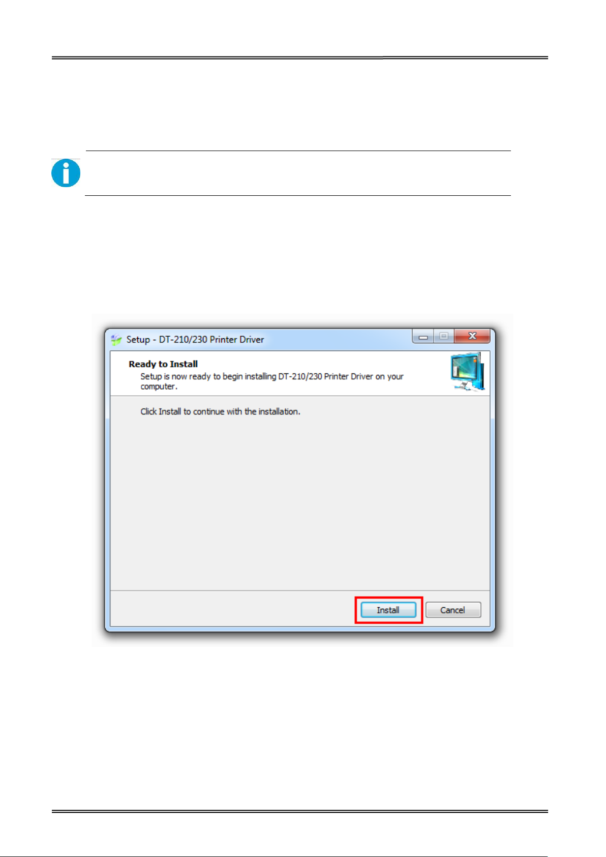
3 INSTALLING DRIVER
Installing the Windows Driver (Compatible with Windows)
Switch off the printer before running the printer driver setup.
Your printer CD-ROM comes with Windows drivers. Go to the related folder and run the driver setup
installer.
1. Double click the driver. You will see the screen as below. Click “Install” to continue.
16
Page 22

Tally Dascom DT-210/230 User Guide V1.3
2. Choose the desired port to use, after selecting the “Port” option (USB001 for USB port, com1 for
serial port and LPT1 for parallel port), click “Next” to continue.
3. Click “Finish” to finish the installation process successfully.
17
Page 23

Tally Dascom DT-210/230 User Guide V1.3
3.1 Installation Driver for Ethernet and Wi-Fi Interface
1. Install the printer driver as USB installation.
2. Click “Start”→ “Devices and Printers”, right click on the DT-230 Printer Driver, and then click
“Printer Properties”.
3. Then you will see the screen as below. Click “Ports” → “Add Port”.
18
Page 24
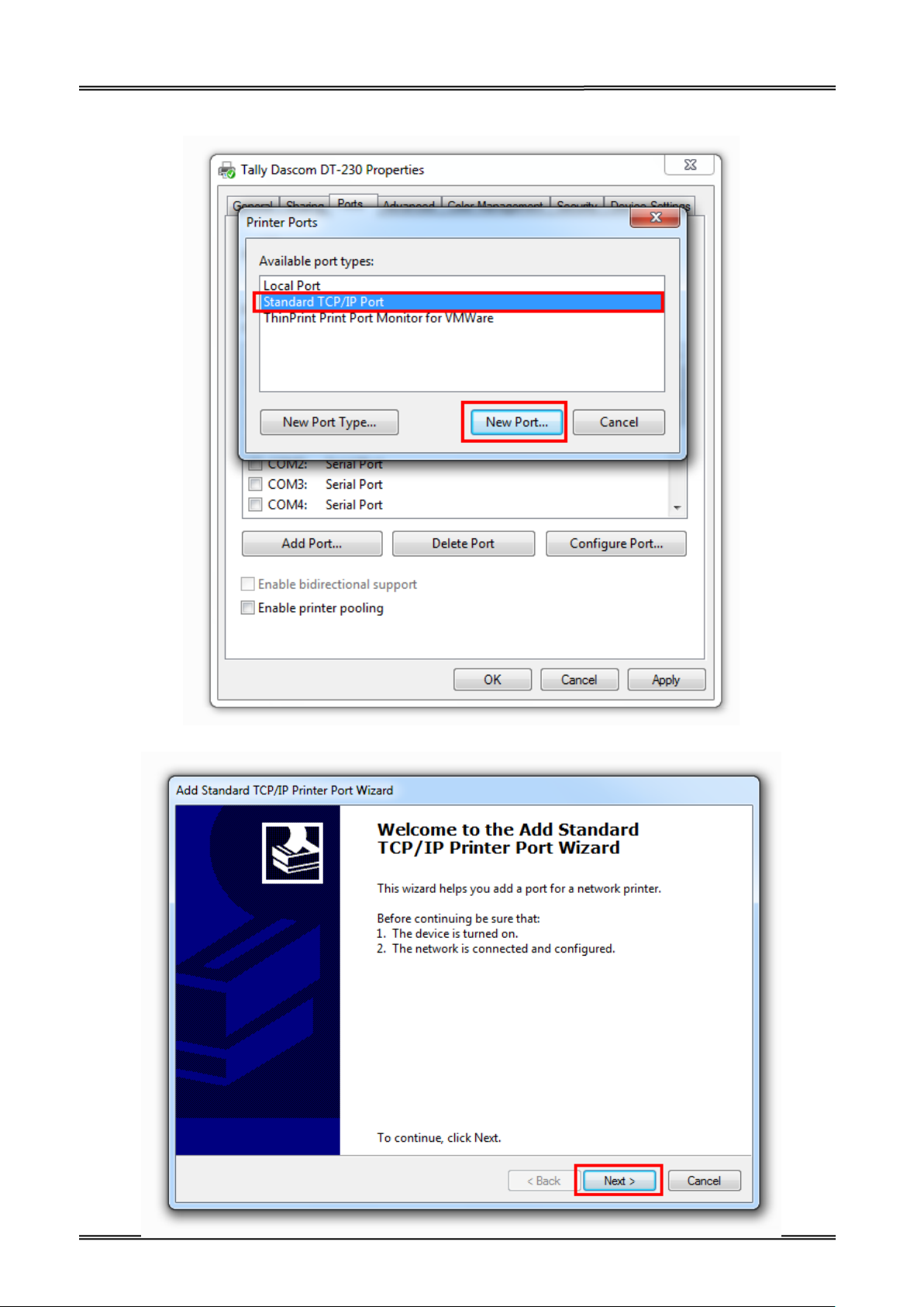
Tally Dascom DT-210/230 User Guide V1.3
4. Select “Standard TCP/IP Port”, and click “New Port”.
5. You will see the screen as below, click “Next” to continue.
19
Page 25

Tally Dascom DT-210/230 User Guide V1.3
6. Complete the “Printer Name or IP Address” and “Port Na me ”.
7. Click “Next” to access the screen as below.
20
Page 26
Tally Dascom DT-210/230 User Guide V1.3
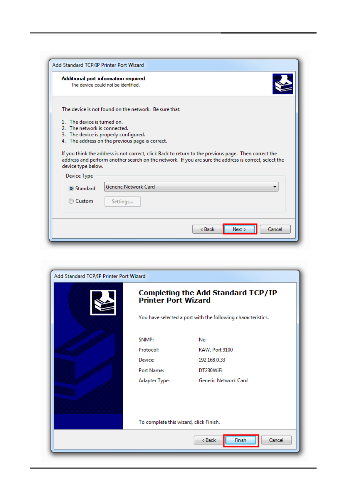
8. And then you will see the screen as below, click “Next” to continue.
9. Click “Finish” to complete the printer driver installation.
21
Page 27

Tally Dascom DT-210/230 User Guide V1.3
10. Click “Start”→ “Devices and Printers”, right click on the DT-230 Printer Driver, and then click
“Printer Properties”. Then click “Ports” → “Configure Port”, finish the setup parameter in the
screen as below. Click “OK” to finish the setup.
22
Page 28
Tally Dascom DT-210/230 User Guide V1.3
3 CONNECTING TO COMPUTER
NOTE!
Be sure to install the driver before connecting the printer to the host computer.
Before installing, disconnect the Power Unit from the printer (as well as turning the power switch
off). Even when the power switch is off, voltage is still present at some points on the circuit board.
Changing components while the power unit is connected can cause damage to the interface board
and the printer.
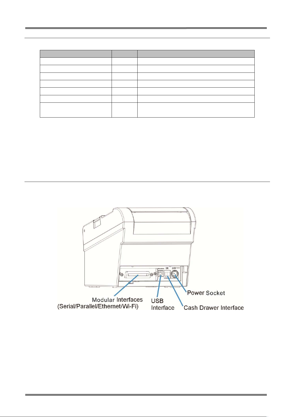
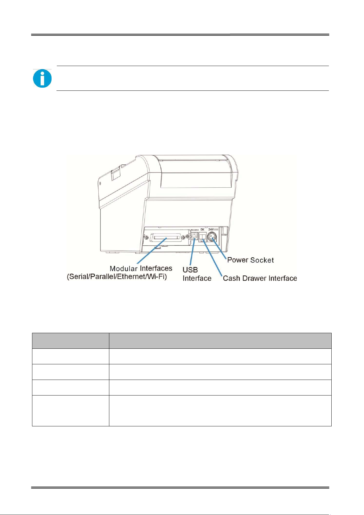
Component Function
Power Socket Connects power cord to the printer.
Cash Drawer Interface Connects Cash Drawer interface cable from the cash drawer.
USB Interface Connects USB interface cable from the host.
Connects optional interface (Serial I/F, Parallel I/F, Ethernet I/F or Wi-Fi
Modular Interface
I/F) from the host.
23
Page 29

Tally Dascom DT-210/230 User Guide V1.3
3.1 For USB Interface
CAUTION!
Be careful not to insert the USB interface cable into the cash drawer kick-out connector.
3.2 For Cash Draw Interface
1. Confirm that the power switch is OFF.
2. Confirm the top and button of the cash drawer cable connector and insert it into
the cash drawer kick-out connector at the back of the printer.
3. Screw the cash drawer’s ground wire to the body of the printer.
CAUTION!
DO NOT connect any other device than the specified cash drawer to the cash drawer
kick-out connector. (Do NOT connect a telephone line either)
24
Page 30
Tally Dascom DT-210/230 User Guide V1.3
3.3 For Serial Interface
WARNING!
Be sure to turn off the power supply for both the printer and host computer before
connecting the cables.
1. Insert the interface cable connector firmly into the interface connector on the
connector panel.
2. When using the connectors equipped with screws, tighten them to secure the
connectors firmly.
3. When using interface cables equipped with a grounding line, attach the ground
line to the screw hole marked “FG” on the printer.
4. Connect the other end of the interface cable to the host computer.
25
Page 31

Tally Dascom DT-210/230 User Guide V1.3
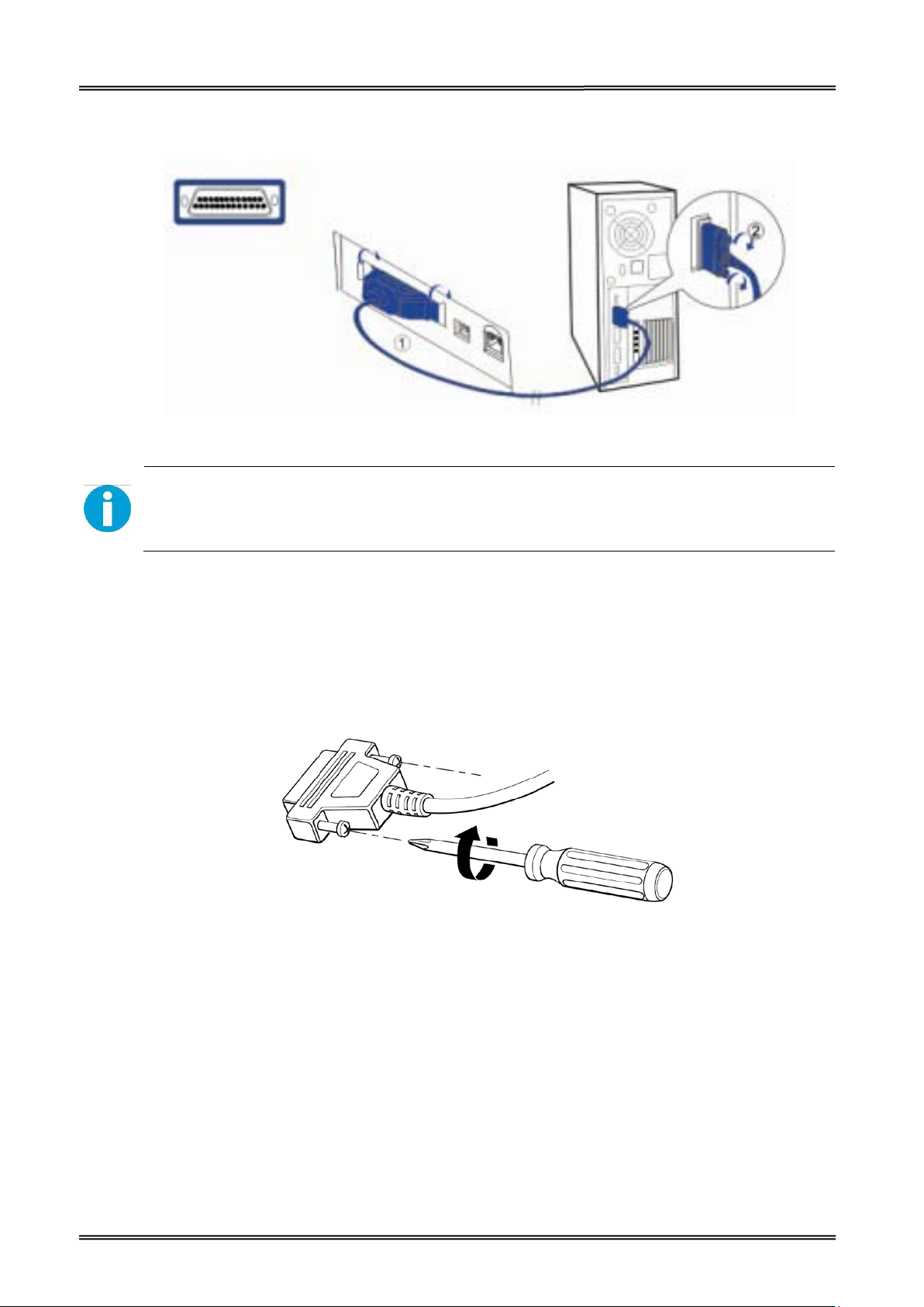
3.4 For Parallel Interface
1. Insert the interface cable connector firmly into the interface connector on the
connector panel.
2. Press down the clips on either side of the connector to lock it in place.
3. When using interface cables equipped with a grounding line, attach the ground
line to the screw hole marked “FG” on the printer.
4. Connect the other end of the interface cable to the host computer.
3.5 For Ethernet Interface
NOTE!
Before installation, make you have installed the driver and the driver for Ethernet
interface (see Installing Driver on page 17)
Connect the printer to a network by a LAN cable via a hub.
Connect a 10/100BASE-T cable to the 10/100BASE-T LAN connector by pressing firmly until the
connector clicks into place.
When using the Ethernet interface, the network configuration is required. Make the settings on the
setup page.
• When LAN cables are installed outdoors, make sure devices without proper
surge protection are cushioned by being connected through devices that do
26
Page 32

Tally Dascom DT-210/230 User Guide V1.3
have surge protection.
Otherwise, the devices can be damaged by lightning.
• Never attempt to connect the customer display cable, drawer kick-out cable,
or the standard telephone line cable to the 10/100BASE-T LAN connector.
1. Switch on printer, press and hold the Reset key for more than 3 seconds with the tip of pen or
small tool. Then the printer will print out a status sheet as shown below.
The following are printed on the status sheet.
•TCP/IP settings.
• Other Information.
Make sure your PC IP address and printer IP address are in the same section.
27
Page 33
Tally Dascom DT-210/230 User Guide V1.3
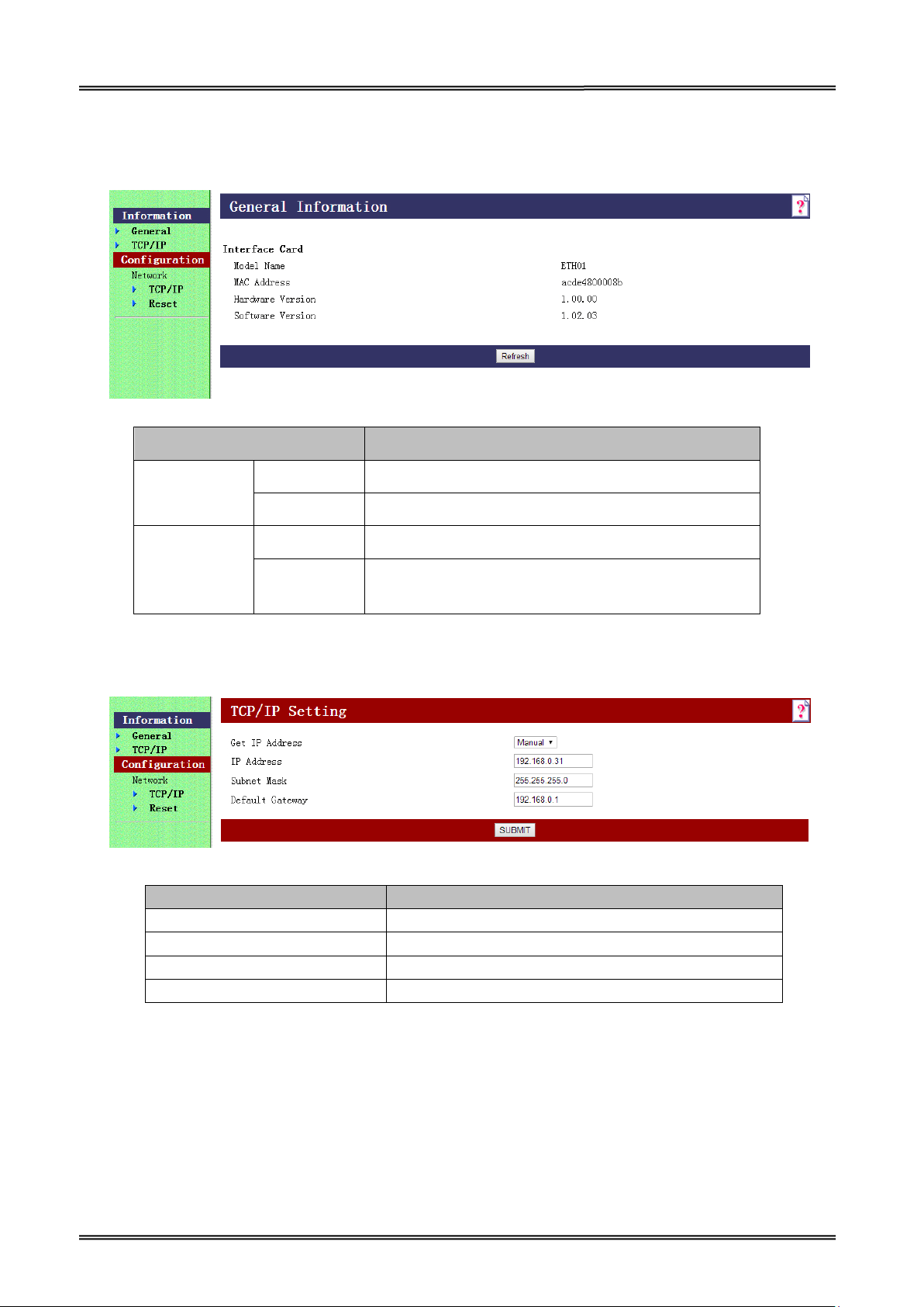
2. The interface is pre-set with the IP address 192.168.0.31. DHCP is disabled. Enter this IP address
in your browser to get access to the built in web page.
Item Explanation
Information General Show the ETH01 information
TCP/IP Show the TCP/IP information
Configuration
Network
TCP/IP Set the TCP/IP information
Reset Reset the ETH01 or return to the factory default
setting
3. Click Configuration→Network→TCP/IP, the default setup for getting IP address is manual, you
can start setting the IP address, subnet mask and default gate way.
Item Explanation
Get IP Address Show the method of setting the IP address
IP Address Show the IP address
Subnet Mask Show the subnet mask of the IP address
Default Gateway Show the default gateway
4. If you want to enable DHCP mode, select “Auto” in Get IP address option.
Or you can do this by pressing the reset button next to the RJ45 socket while you switch on your
printer.
Verify the new setting by pressing the button after some seconds again. The new IP address is
being printed.
28
Page 34

Tally Dascom DT-210/230 User Guide V1.3
5. After TCP/IP setup, click “Submit”, you will see the following interface. Then click “Reset” button,
the parameter will be valid.
6. Configuration page supports initializing TCP/IP parameter. Click Configuration→Network→Reset,
you will see “FACTORY DEFAULT” button. Click the button, Ethernet board TCP/IP parameter will
return to factory default setup. IP Address is 192.168.0.31.
29
Page 35

Tally Dascom DT-210/230 User Guide V1.3
3.6 For Wireless LAN Interface
If your printer connected to the computer with Wireless Ethernet, there are two ways of connection
modes: AP mode and STA mode.
When using the wireless LAN interface, the network configuration is required. Make the settings on
setup page.
If your printer connected to the computer with Wireless Ethernet, there are two ways of connection
modes: AP mode and STA mode.
1. Switch on printer, press Reset key with the tip of pen or a small tool. Printer will print out a Wi-Fi
parameter as shown below.
Reset Button
30
Page 36

Tally Dascom DT-210/230 User Guide V1.3
2. You will see “DT-230_WIFI” in the wireless network connection list. Click “Connect”.
3. Double click “DT-230_WIFI” for connection. It will display “Connected” if connection is successful.
31
Page 37

Tally Dascom DT-210/230 User Guide V1.3
3.6.1 Get IP Address
There are two methods to get the IP address of the printer. One way is to look at the Wi-Fi
parameter sheet. The other way is to look into the Wi-Fi connection details after your printer is
connect to the computer via Wi-Fi module. Here is the procedure:
1. Open the control panel Network and Internet Network Connections.
Then you can see this page: double click “Wireless Network Connection”.
32
Page 38

Tally Dascom DT-210/230 User Guide V1.3
2. Click “Details” button on this page.
33
Page 39

Tally Dascom DT-210/230 User Guide V1.3
3. Then you can see the IP Address on the Property “IPv4 Default Gateway”: 192.168.0.33
There are two kinds of working mode for Wlan board connection to the PC. One is AP mode, the
other one is STA mode. AP means Access Point (AdHoc Mode); STA means Station mode (Infra
Structure Mode). We would suggest you use AP mode for your initial usage.
34
Page 40

Tally Dascom DT-210/230 User Guide V1.3
admin
admin
3.6.2 Wlan Setup - AP mode
1. Visit IP Address http://192.168.0.33. Default username is “admin” with password “admin” for
the first time to log in. You will see the following Wi-Fi setup page. Click “Submit” button after
modifying the parameter. Restart printer, new parameter will be valid.
35
 Loading...