

Page 1

Page 2

Page 3

Tally Dascom DM-210/220
I
Important Safety Instructions (English)
Read the following instructions thoroughly before starting up your printer.
• Never carry out maintenance or repair work yourself. Always contact a qualified service
technician.
• Keep this Operator’s Manual in a place which is easily accessible at all times.
• Place the printer on a solid and even base so that it cannot fall.
• Never place the printer in the vicinity of inflammable gas or explosive substances.
• Ensure the printer is connected to a socket with the correct mains voltage.
• Always disconnect the printer from the mains before opening the device to perform
maintenance work or remedy errors.
• Do not expose the printer to high temperatures, direct sunlight or dust.
• Keep all liquids away from the printer.
• Protect the printer from shock, impact and vibration.
• Make sure that both of the printer and the computer are switched off before connecting the
data cable.
• The print head will become very hot during printing; avoid contact with the print head after
printing has finished.
• Do not perform any operation or action in any way other than those provided in this manual.
When in doubt, contact your dealer or your customer support.
Page 4

Tally Dascom DM-210/220
II
Wichtige Sicherheitshinweise (German)
Lesen Sie bitte diese Sicherheitshinweise durch, bevor sie den Drucker in Betrieb nehmen.
Führen Sie Wartungsarbeiten und Reparaturen keinesfalls selbst aus, sondern verständigen
Sie immer einen qualifizierten Servicetechniker.
Bewahren Sie diese Dokumentation an einem jederzeit zugänglichen Ort auf.
Den Drucker auf stabilem und ebenem Untergrund so aufstellen, dass er nicht zu Boden fallen
kann.
Stellen Sie den Drucker keinesfalls in der Nähe von leicht entzündlichen Gasen oder
explosiven Stoffen auf.
Den Drucker nur an eine Steckdose mit der richtigen Spannung anschließen.
Wenn Sie den Drucker vom Netz trennen wollen, den Drucker ausschalten und immer den
Netzstecker an der Steckdose ziehen.
Den Drucker weder hohen Temperaturen noch direktem Sonnenlicht und Staub aussetzen.
Keine Flüssigkeiten mit dem Drucker in Berührung bringen.
Den Drucker keinen Erschütterungen, Stößen oder Vibrationen aussetzen.
Sicherstellen, dass der Drucker und der Computer ausgeschaltet sind, bevor das Datenkabel
angeschlossen wird.
Der Druckkopf wird während des Druckens heiß. Vor dem Berühren deshalb einige Zeit
abkühlen lassen.
Weichen Sie bei der Bedienung des Druckers nicht von den Anweisungen in der
Dokumentation ab. Bei Unklarheiten wenden Sie sich bitte an Ihren Händler oder Ihren
Kundendienst.
Page 5

Tally Dascom DM-210/220
III
Consignes importantes de sécurité (French)
Lire attentivement les instructions suivantes avant de mettre l’imprimante en service.
Ne jamais effectuer soi-même les travaux d’entretien et de réparations. Contacter toujours un
dépanneur qualifié.
Placer l’imprimante sur un support stable de façon à ce qu’elle ne puisse pas tomber.
Ne jamais placer l’imprimante à proximité de sources de gaz aisément inflammables ou de
substances explosives.
Ne connecter l’imprimante à une prise que lorsque la tension est correcte.
Pour déconnecter l’imprimante de l’alimentation principale, mettre l’imprimante hors tension
et toujours débrancher le connecteur secteur de la prise murale.
Ne pas exposer l’imprimante à des températures élevées, à la lumière directe du soleil ou à la
poussière.
Ne pas mettre l’imprimante en contact avec des liquides.
Ne pas exposer l’imprimante à des chocs, impacts ou vibrations.
S’assurer que l’imprimante et l’ordinateur sont hors tension avant de connecter le câble de
données.
La tête d’impression est brûlante pendant l’impression. C’est pourquoi laissez-la refroidir
quelques instants avant d’y toucher.
N'exécutez aucune opération ni action d'une autre manière que celle indiquée dans ce
manuel. En cas de doute, veuillez contacter votre distributeur ou service après-vente.
Page 6

Tally Dascom DM-210/220
IV
Indicazioni di sicurezza importanti (Italian)
Prima di mettere in funzione la stampante, leggere attentamente le seguenti indicazioni.
Non eseguire mai da sé gli interventi di manutenzione e riparazione, ma rivolgersi sempre a
un tecnico di assistenza qualificato.
Conservare le presenti istruzioni per l’uso in un luogo sempre accessibile.
Collocare la stampante su una superficie stabile, per evitare che cada a terra.
Non collocare la stampante in prossimità di gas facilmente infiammabili o di sostanze
esplosive.
Collegare la stampante a una presa di corrente con tensione adeguata.
Per scollegare la stampante dalla rete di alimentazione, spegnere la stampante e disinserire
sempre il connettore di rete dalla presa.
Non esporre la stampante ad elevate temperature né alla luce solare diretta e alla polvere.
Evitare il contatto della stampante con liquidi.
Non esporre la stampante a colpi, scosse o vibrazioni.
Verificare che la stampante e il computer siano spenti prima di collegare il cavo di
trasmissione dati.
Durante la stampa, la testina si surriscal-da notevolmente. Prima di toccarla, se necessario
opportuno quindi lasciarla raffreddare qualche istante.
Non eseguire alcuna operazione o azione se non nella maniera descritta nel presente manuale.
In caso di dubbio, contattare il rivenditore o dalla società incaricata dell’assistenza.
Page 7

Tally Dascom DM-210/220
V
Instrucciones de seguridad importantes (Spanish)
Lea las siguientes instrucciones con esmero antes de poner la impresora en servicio.
Nunca lleve a cabo trabajos de mantenimiento o reparación Ud. mismo, sino consulte a un
técnico de servicio calificado.
Guarde las presentes instrucciones de servicio en un lugar de fácil acceso en cualquier
momento.
Ponga la impresora sobre un base estable de manera que no pueda caer al suelo.
Nunca coloque la impresora en la vecindad de gases de fácil inflamabilidad o sunstancias
explosivas.
Asegure conectar la impresora sólo a un enchufe con un voltaje correcto.
Cuando quiera desconectar la impresora de la red, apague la impresora y siempre tire la
clavija de alimentación del enchufe.
No exponga la impresora a temperaturas altas, a la luz solar directa y al polvo.
No ponga la impresora en contacto con fluidos.
Nunca exponga la impresora a sacudidas, choques o vibraciones.
Asegúrese de que la impresora y el ordenador estén apagdos antes de conectar el cable de
datos.
La cabeza de impresión se pone muy caliente durante la impresión. Por lo tanto, deje enfriarlo
algún tiempo antes de tocarla.
No permita que se realice cualquier operación o acción de una forma diferente a lo que se
señala en el manual. En caso de duda, póngase en contacto con su comerciante o con su
servicio post-venta.
Page 8

Tally Dascom DM-210/220
VI
Правила по технике безопасности. (Russian)
Прочитайте, пожалуйста, инструкцию по технике безопасности перед включением в работу
принтера.
Не выполняйте технические работы и ремонт техники самостоятельно, но сообщайте о
неисправностях квалифицированным сервисным техникам.
Данная инструкция должна быть всегда доступна каждому пользователю.
Установите принтер на ровном и стабильном месте так, чтобы он не смог упасть на пол.
Ни в коем случае не ставьте принтер вблизи легко воспламеняющихся газов и
взрывчатых веществ.
Включайте принтер в розетку только с соответствующим напряжением.
Если Вы хотите отключить принтер от напряжения, сначала выключите принтер сам и
затем выньте штекер из розетки.
Берегите принтер от нагревания, от попадания на него прямых солнечных лучей и
пыли.
Не допускайте попадания жидкости на принтер.
Нельзя подвергать принтер тряске, ударам и вибрации.
Убедитесь, что принтер и компьютер выключены, только после этого соедините принтер
с компьютером.
Печатающая головка нагревается во время работы принтера. Поэтому подождите
какое-то время, прежде чем дотронуться до нее.
Пользуйтесь принтером так, как это написано в документации. Если у Вас возникают
неясности, обращайтесь с вопросами к Вашим продавцам или в сервисный центр.
Page 9

Tally Dascom DM-210/220
VII
Instruções Importantes sobre Segurança (Portuguese)
Leia as instruções de segurança antes de usar a impressora.
Consulte sempre um técnico qualificado para executar uma reparação .
Coloque a impressora sobre uma base sólida e nivelada, para que ela não sofra quedas.
Jamais instale a impressora nas proximidades de lugares onde haja gás inflamável ou
substâncias explosivas.
Assegure-se de conectar a impressora à tomada elétrica com a voltagem apro-priada.
Quando desligar a impressora da rede, desligue sempre a impressora e retire o cabo da
tomada.
Não exponha a impressora a temperaturas altas ou luz solar direta.
Não aproxime substâncias líquidas da impressora.
Proteja a impressora de choques, impactos e vibrações.
Desligue a impressora e o computador antes de conectar o cabo da rede.
A cabeça da impressora pode ficar muito quente . Portanto, espere algum tempo antes de
tocá-la.
Não faça nenhuma operação ou ação além das recomendadas neste manual. Em caso de
dúvida, contate seu revendedor ou companhia de serviço.
Page 10

Tally Dascom DM-210/220
VIII
Önemli Güvenlik Talimatları (Turkish)
Lütfen, yazıcıyı işletime geçirmeden önce bu güvenlik talimatlarını bütünüyle dikkatle okuyun.
Bakım ve tamir çalışmalarını kesinlikle ve hiçbir surette kendi başınıza yapmayın; her zaman
kalifiye bir uzman servis-teknisyenine haber verin.
Yazıcıyı, üzerinden yere düşmesi mümkün olmayacak sabit ve düz bir zemine yerleştirin.
Yazıcıyı kesinlikle ve hiçbir surette kolayca yanabilecek gaz veya patlayıcı maddeler içeren
nesnelerin yakınına koymayın.
Yazıcı akım kablosunu sadece doğru gerilime sahip bir prize takın.
Yazıcıyı şebeke ağından ayırmak istediğinizde, yazıcıyı kapatın ve ağ-fişini her zaman prizden
çıkartın.
Yazıcıyı ne yüksek ısılı ne de doğrudan güneş ışığına ve toza mâruz kalan mekânlarda
bulundurun.
Yazıcı hiçbir sıvı maddeyle temasta olmamalıdır.
Yazıcı hiçbir sarsıntıya, darbeye veya titreşime mâruz kalmamalıdır.
Veri kablosu bağlanmadan önce hem yazıcının hem de bilgisayarın kapalı olduklarından emin
olmalısınız.
Yazıcının başı basma esnasında yüksek ısıya ulaşıyor. Bu yüzden lütfen dokunmadan önce kısa
süre soğumasını bekleyin.
Yazıcının işletimi ve kullanımında bu dokümantasyondaki talimatların hiç dışına çıkmayın.
Sorunlu görünen hususlarda lütfen imâlatçınıza veya müşteri hizmetleri servisinize başvurun.
Page 11

Tally Dascom DM-210/220
IX
TRADEMARK ACKNOWLEDGEMENTS
“IBM” is a trademark of International Business Machines Corporation.
“EPSON” is a trademark of Epson America Incorporated.
“DEC” is a trademark of Digital Equipment Corporation.
“Centronics” is a trademark of Centronics Data Computer Corporation.
“DOS” is a trademark of Microsoft Corporation.
“SAP” is a trademark of SAP AG.
“Windows”, “Windows 7”,”Windows 8”, “Windows 95”, “Windows 98“, “Windows NT”, “Windows
2000”, “Windows 2003/2008/2013 Server”, “Windows XP” and “Windows Vista” are trademarks of
Microsoft Corporation.
All other product names and company names appearing in this manual are the registered
trademarks or trademarks of the individual companies.
Page 12

Tally Dascom DM-210/220
X
Page 13

Tally Dascom DM-210/220
TABLE OF CONTENTS
1 PRINTER INSTALLATION GUIDE ................................................................................................... 1
1.1 Unpacking the Printer................................................................................................................ 1
1.2 Placing the Printer ..................................................................................................................... 2
1.3 Printer Components................................................................................................................... 3
1.4 Connecting the Interfaces .......................................................................................................... 4
1.5 Connecting the Power................................................................................................................5
1.6 Loading Paper............................................................................................................................ 6
1.7 Installing Ribbon Cartridge......................................................................................................... 7
1.8 Installing the Printer Driver ........................................................................................................8
2 CONTROL PANEL OPERATION ..................................................................................................... 10
3 TROUBLESHOOTING ................................................................................................................... 12
3.1 Processing Indicator Error........................................................................................................ 12
3.2 Processing Printing Error..........................................................................................................12
3.3 Removing Jammed Paper......................................................................................................... 12
4 SPECIFICATIONS.......................................................................................................................... 13
4.1 Data Sheet............................................................................................................................... 13
4.2 Interfaces................................................................................................................................. 15
4.2.1 USB interface..................................................................................................................... 15
4.2.2 Cashbox interface ..............................................................................................................15
4.2.3 Serial interface .................................................................................................................. 16
4.2.4 Parallel interface................................................................................................................ 16
4.3 Power Supply........................................................................................................................... 18
5 CHARACTER CODE PAGES ........................................................................................................... 19
6 PRINTING CONTROL COMMAND SETS........................................................................................ 26
FCC STATEMENT............................................................................................................................. 27
DASCOM REPRESENTATIVES.......................................................................................................... 28
Page 14
Tally Dascom DM-210/220
1 Printer Installation Guide
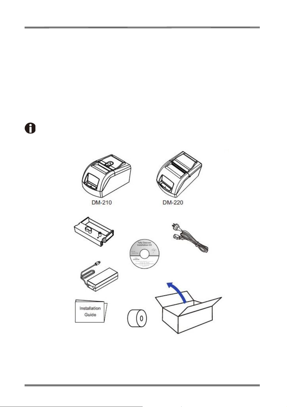
1.1 Unpacking the Printer
Open the packaging, lift the printer out of the cardboard box and remove the remaining packaging
material. Check the printer for any visible transport damage and missing items. If you find any
transport damage or any accessories are missing, please contact your dealer for assistance.
Please keep the packaging material for future transportation.
The shipping list varies with different customized order requirements.
1
Page 15

Tally Dascom DM-210/220
1.2 Placing the Printer
Place the printer on a solid, flat, stable surface; ensuring that the printer is positioned in such a way
that it cannot move, and that there is easy access to the control panel and paper input devices. Also
ensure that there is enough space for sufficient ventilation and for the printed output.
When selecting the printer location, observe the following additional instructions:
Never place the printer near to any flammable gas or explosive substances.
Do not expose the printer to direct sunlight. If you cannot avoid placing the printer near a
window, protect it from the sunlight with a curtain.
When connecting a computer to the printer, make sure the maximum recommended cable
length is not exceeded.
Ensure sufficient distance between the printer and any heating devices or radiators.
Avoid exposing the printer to extreme temperature or air humidity fluctuations. Avoid
exposure to dusty environments.
It is recommended the printer is installed in a position which reduces noise exposure to the
work place during printing.
2
Page 16
Tally Dascom DM-210/220
(DM210 only)
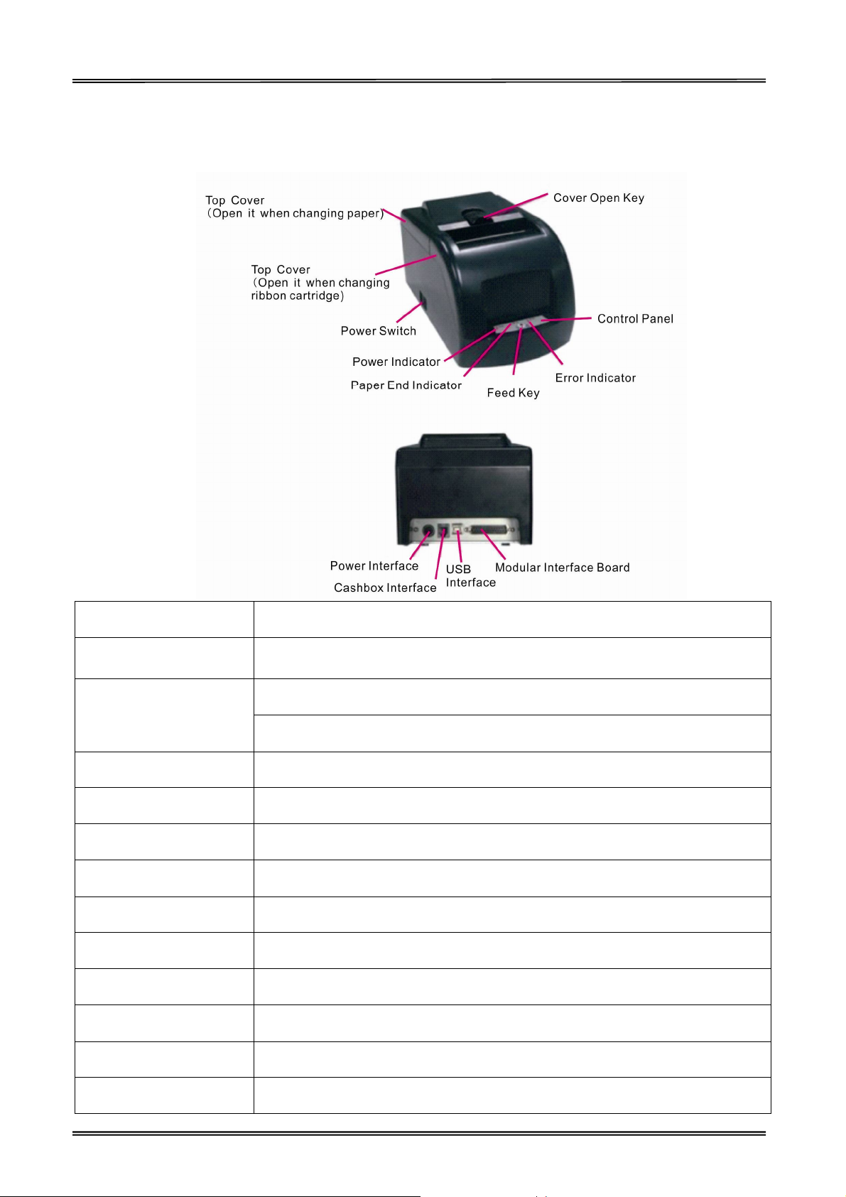
1.3 Printer Components
Components Function
Cover Open Key Open the Printer Cover (DM-210 only).
Open the cover when loading or reloading roll paper.
Top Cover
Open the cover when ribbon cartridge
Power Switch Powers printer ON or OFF.
Power Indicator Shows printer power on or not.
Paper End Indicator Shows roll paper out or not.
Feed Key Press the key to feed paper.
Error Indicator Shows error occurs or not.
Control Panel Shows printer status.
Power supply Socket Connects power cord to the printer.
Cashbox Interface Connects Cashbox interface cable from the cashbox.
USB Interface Connects USB interface cable from the host.
Modular Interface Board Connects serial interface or parallel interface from the host.
3
Page 17
Tally Dascom DM-210/220
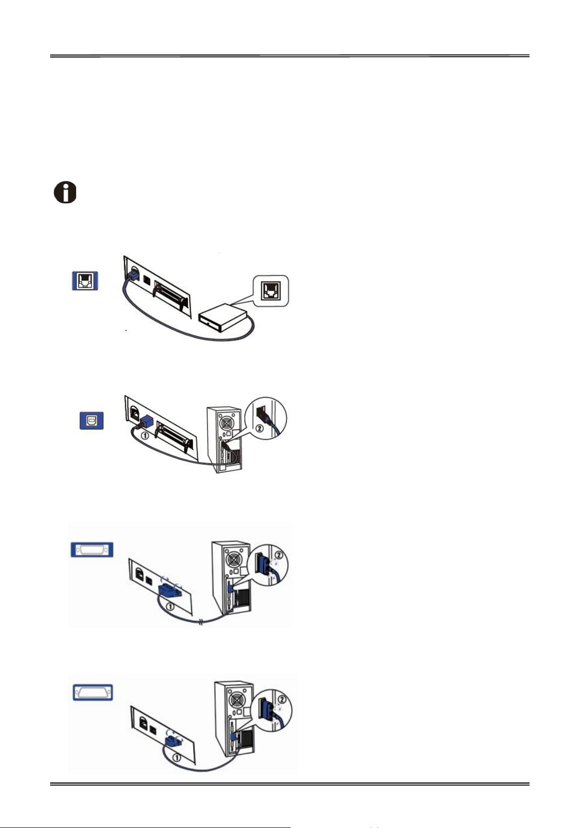
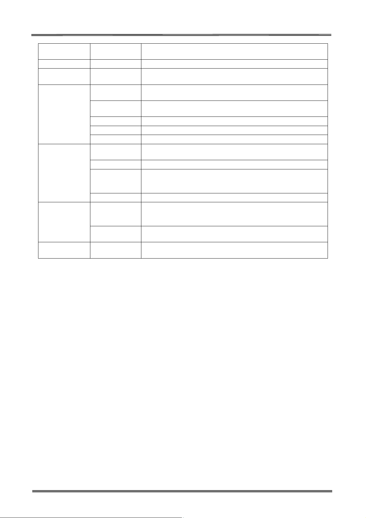
1.4 Connecting the Interfaces
The USB, Cashbox, Serial/Parallel interface are located at the rear of the printer. Choose the
interface which suits your system.
Make sure the printer and the computer are switched off before connecting or
disconnecting the interface cable to prevent electrical damage to the interfaces.
Connecting cashbox interface
Connecting USB interface
Connecting parallel interface (modular, option)
Connecting serial interface (Modular, option)
4
Page 18

Tally Dascom DM-210/220
1.5 Connecting the Power
Checking the printer voltage
Make sure that the device has been set according to your country’s power supply voltage. To
do this, check the rating plate at the rear of the printer. Contact your dealer if the setting is
incorrect.
1. Make sure the printer and the computer are powered off ①.
2. Connect the power cord to the power adapter ②, and connect the power adapter to the power
supply socket at the rear of the printer ③. Ensure the power cord is securely connected. Finally,
connect the power cord plug to a mains socket on the wall ④.
Power on and power off
1. Press the power switch to the “I” position to turn on the printer.
Upon power-on, the Power LED indicator light up.
2. Press the power switch to the “O” position to turn off the printer.
5
Page 19

Tally Dascom DM-210/220
1.6 Loading Paper
1. Keep power on and open the top cover.
2. Insert the end of paper into the entry of paper path, then sent it in with even force until the feeder
motor drives to feed in the paper automatically.
3. Close the top cover
The end of paper should be cut regularly and inserted into the entry of paper path, then sent it
in with even force until the feeder motor drives to feed in the paper automatically.
If paper jams results, pull out the paper when the automatic feeder motor stops. Cut off the
fold side of the paper and reload it.
If black mark is valid, the paper will be fed to the printing initial position.
6
Page 20

Tally Dascom DM-210/220
1.7 Installing Ribbon Cartridge
1. Open top covers to show up the printhead.
2. Turn the ribbon knob on the right side in the direction indicated by the arrow on the cartridge to
remove any slack.
3. Insert the ribbon between the print head and the platen, and press it in until it clicks into place.
4. Turn the knob again to remove any slack.
5. Close the cover.
7
Page 21

Tally Dascom DM-210/220
1.8 Installing the Printer Driver
Installing the Windows Driver (Compatible with Windows)
Switch off the printer before running the printer driver setup.
Your printer CD-ROM comes with Windows drivers. Go to the Drivers folder and run the installer
“DriverSetup.exe”.
Installation guide for USB, serial and parallel driver program
1. Double click the “DriverSetup”. You will see the screen as below. Click “Next” to continue.
2. You might see the screen as below. Select the desired printer driver, and then click “Next” to
continue.
8
Page 22

Tally Dascom DM-210/220
3. Choose the desired port to use, and then click “Next” to continue.
4. Click “Finish” to finish the installation process successfully.
5. You will see the screen as below. Click “OK” to install the printer driver successfully.
9
Page 23

Tally Dascom DM-210/220
2 Control Panel Operation
There are power indicator, paper end indicator, error indicator and feed key in the printer.
When pressing the Feed key, if the black mark detection is off, paper will be fed until Feed key is
released; otherwise, the paper will be fed to the next black mark and stop.
Indicator Illustration
That the green indicator is on indicates that the power is on. Here are the illustrations for error
indicators:
Error
indicator
Blink On Memory Error
Blink Off
Blink Blink
On Blink Paper end
Paper end
indicator
Indications Disposal
Check the SRAM chip, data bus,
address line and selected signal,etc.
The print head is
over-heated
The position of the
carriage is wrong
Recover automatically until the
temperature drops down.
Check the stepper motor of the
carriage, transmission mechanism,
initial position sensor and drive
circuit, etc.
Load paper.
Self-test Printing and Hexadecimal Dumping
Turn off the printer after the ribbon cartridge and roller paper are installed, hold the feed key while
power on, and then the printer will print out the self-test page.
After the self-test completed, if there feed key is pressed, the printer will enter bidirectional printing
adjustment state. If receiving data without pressing feed key, the printer will enter hexadecimal
printing state.
If you do not need to implement the alignment or hexadecimal printing, please switch off the printer
and restart the printer for printer normal operation.
10
Page 24

Tally Dascom DM-210/220
Bidirectional Printing Adjustment
When typefaces are blurred or vertically misaligned, it is necessary to do the bidirectional printing
quality adjustment.
After self-test completed, the alignment parameter for bidirectional printing will change circularly
along with pressing feed key and the printer will print out the reference typeface.
When the printing quality becomes best, in other words, both the upper and lower rows of “H” are
best aligned, you can turn off the power and the printer will save the parameters automatically.
11
Page 25

Tally Dascom DM-210/220
dicator always on and
3 Troubleshooting
Your printer is extremely reliable, but occasionally problems may occur. This chapter provides
information on some of the common problems you may encounter and how you may solve them. If
you encounter problems that you can not resolve, please contact your dealer for assistance.
Read the following instructions before maintenance and avoid operating beyond your capacity, so as
to prevent injury to you and damage to the printer.
3.1 Processing Indicator Error
Phenomenon Potential Problem Solution
Incorrect power supply cable
connections and power outlet
No indicators on
Error In
Paper End Indicator flashes
Error Indicator flashes Print Head overheated Reprint until it cools
The printer does not switch on.
PCB damaged Contact your dealer for assistance
Paper end Reload the roll paper
Check the power supply cable connections and the
power outlet and correct them
Switch on the printer
3.2 Processing Printing Error
Phenomenon Potential Problem Solution
Incorrect roll paper installation Check if the roll paper is installed correctly
Blurred printing or spot
Unqualified roll paper Use recommended roll paper
Paper stucked
Paper can not be fed.
The printer does not switch on.
Open the printer cover, check the paper
path and remove jammed paper
Switch on the printer
Horizon print words missing Printhead pin damaged Contact your dealer for assistance
3.3 Removing Jammed Paper
Turn the printer off and open the top cover.
Open the printer cover and remove the jammed paper.
Printhead may be hot, please move the printhead by moving the carriage.
12
Page 26

Tally Dascom DM-210/220
4 Specifications
4.1 Data Sheet
Print method
Print direction
Resolution
Print speed 4.3lps(4.3 line / sec at 42 columns)
Paper feed
speed
Print
Parameter
Cartridge
Ribbon
Copies
Paper Feed
Memory RAM
Fonts
Detect
Function
Key and
LED Indicator
Power Supply
Paper Handle
Print width
Interface
Power Sleep
Chinese
Alphanumeric
Code page
Black Mark
Detection
Key
Power indicator
Paper indicator
Error indicator
Input
Output
Paper type
Paper width
Paper thickness
Paper roll
diameter
Paper load
Paper cut
9 pin dot matrix (Pin ф0.30mm)
bidirectional logic-seeking
max 160dpiH x 144dpiV
max 5.51ips (14cm/s)
42cpl @ 16.7cpi (7x8 matrix)
Cashbox: DC 24V, 1A, 6 line RJ-11 connector
USB 2.0: Full Speed, standard type B Connector
Serial RS232C: 25-pin Sub-D (f) connector; supports DTR or
XON/XOFF handshaking protocol; baud rate 4800~38400BPS; data
Format 1 initial bit + 8 data bit + 1 or 2 stop bits, no Parity.
Parallel CENTRONICS: 25-pin Sub-D (m) connector, 8-bit parallel;
supports BUSY/ACK handshaking protocol.
Yes
NH37701 (Purple), Lifetime: 3000,000 characters (Compatible to
ERC-39)
NH37703 (Black), Lifetime: 1000,000 characters
1+1 (Thickness: 0.05~0.08mm/page; Total thickness: ≤0.16mm)
Friction feed
Max. 32Kbytes data buffer
GB18030_2000 16x16
7x8 and 9x8 ASCII font
PC437/PC850/PC860/PC863/PC865/PC858
In the direction of paper feed:
Mark height 5mm; Mark width min 12mm;
Mark reflectivity < 10%; Non-mark reflectivity > 75%;
Mark to initial print position: 27mm; Mark to tear position 47mm;
Factory default: Mark detection on the right for receipt face; Can be
changed to left using mark control commands.
Feed key
Green LED
Red LED
Red LED
External power adapter
AC 100V-240V 50-60Hz
DC 24V±5%, 2.1A, A-1009-3P interface
Good quality normal white roll paper or carbonized roll paper
76.2±0.5mm (3 inch)
0.06~0.085mm for single paper
Max. OD ф83mm
ID ф10+2/-0mm
Upward cover open and Easy paper loading
DM-210: Manual tear;
DM-220: Auto-cutter; support full cut and partial cut.
Full cut (Cuts the paper completely)
13
Page 27
Tally Dascom DM-210/220
Emulation
Noise
Operating
condition
Storage
Physical Spec.
Reliability
Software
Function
Certification
condition
Dimensions
Color
Weight
Printhead
lifetime
MTBF
Cutter lifetime
(DM-220 Only)
MCBF
Driver program
Utilities
Partial cut (one point left uncut)
Note: The point length is 2% of the paper width.
ESC/POS Compatible command set
The noise level is less than 50 dBA (to be measured following ISO
7779 and ISO 9296).
0~40℃/40~90%RH
-40~55℃/≤93%RH
156×260×130 (L×W×H mm)
Black
Approx. 1.85kg (excluding roll paper)
150,000,000 characters
100,000 hours
500,000 cuts
Conditions: Paper thickness < 0.16mm
Max frequency: 20 cuts/min
10,000,000 lines
32bit: Windows (Win 7/Vista/XP/2000)
64bit: Windows (Win 7/Vista/XP/2000)
Compatible to the EPSON POS Application (ESC/POS OS)
Setup tool (The printer parameter can be uploaded and
downloaded, and the firmware version updating is supported.)
CCC, CE-Mark(CB, EMV, EMC), UL, FCC, REACH, WEEE/RoHS, GCPO,
Labeling/Packaging and Energy Star
14
Page 28

PIN No.
Description
Classic wire color
1 VBUS
Red
2 D-
White
3 D+ Green
4 GND Black
4.2 Interfaces
Power Supply interface, USB interface and cashbox interface are standard interfaces for the printer.
Serial interface and Parallel interface are optional interfaces for the printer.
The interface pin assignment is listed below.
4.2.1 USB interface
USB interface pin assignment
USB interface connector diagram
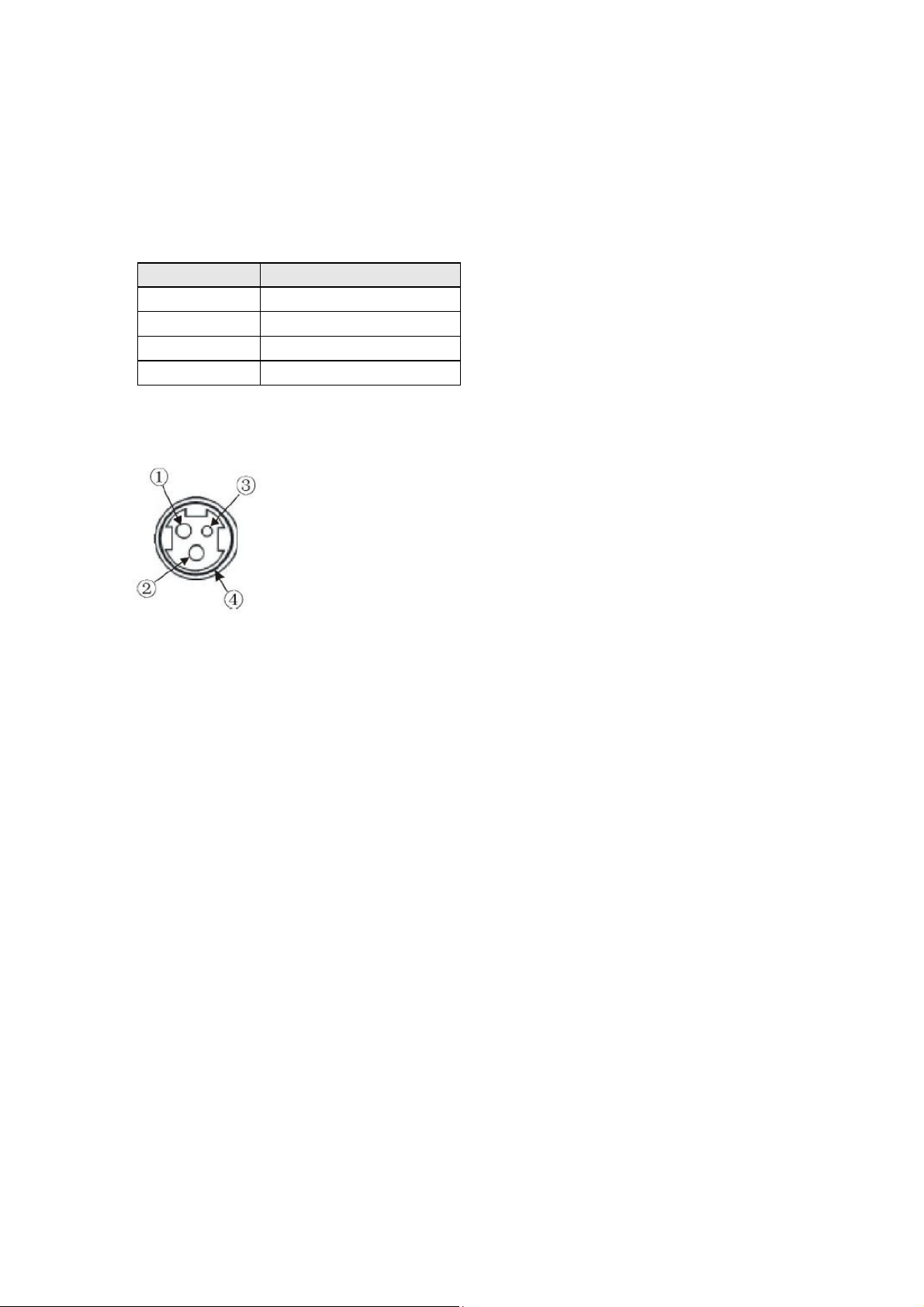
4.2.2 Cashbox interface
Cashbox interface pin assignment
Pin No.
1 Structure GND ---
2 Cashbox drive signal Output
3 NC Empty
4 DC +24V Output
5 Cashbox drive signal Output
6 Signal GND ---
Cashbox interface connector diagram
Description Direction
Page 29
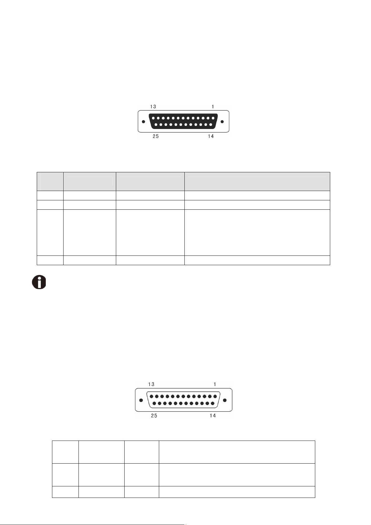
4.2.3 Serial interface
The serial interface of this printer is compatible with RS-232C, use DB25 hole type socket, support
hardware handshaking protocol, the default baud rate and data format are 9600BPS, 8 data bit, no
parity, and 1 stop bit. Below is the pin No of the serial interface socket.
Pin signal definition of serial interface
Pin
No
Signal Name Direction Illumination
2 TXD From printer to PC Send data from printer to PC
3 RXD From PC to printer Printer receive data from PC
When the signal is “negative”, it means that
the printer is “busy” and can not receive
20 DTR From printer to PC
data; While the signal is “positive”, it means
that the printer is “ready” and can
receive the data.
1,7 GND ——— GND
The default baud rate is 9600 BPS and the baud rate can be changed by sending 16 Hex. command 1C
AA 22 XX.
XX: 00 indicates 1200 BPS, 01 indicates 2400 BPS, 02 indicates 4800 BPS,
03 indicates 9600 BPS, 04 indicates 19200 BPS, 05 indicates 38400 BPS.
4.2.4 Parallel interface
The parallel interface of this printer is compatible with CENTRONICS, support BUSY /ACK
handshaking protocol, use DB25 pin type interface.
Pin No. of DB25 pin interface as below
Parallel Interface Pin No.25 Below is the pin signal definition of parallel interface socket:
Pin
Signal Name Direction
Illumination
No
Select trigger, input data when the signal is at
1 /STB Input
falling edge.
2 DATA1 Input These signals indicate the parallel data
Page 30

3
4
5
6
7
8
9
DATA2
DATA3
DATA4
DATA5
DATA6
DATA7
DATA8
Input
Input
Input
Input
Input
Input
Input
10 /ACK Output
11 BUSY Output
12 PE Output
13 SEL Output
information from the first to eighth bits. For
each signal, when the logic is “1” indicates “high
level”, when the logic is “0” indicates “low level”.
For responsion pulse, “low” level indicates that
the printer has accepted the data and be ready
for accepting next data.
“High” level indicates that the printer is “busy”
and can not accept data now. “Low” level
indicates “idle”.
Drop down to “Low” level with resistance,
“High” level indicates paper end.
Full up to “High” level with resistance and the
“High” level indicates the printer is online.
15 /ERR Output
Full up to “High” level with resistance and the
“High” level indicates no error.
14 /AUTOFD Input Auto paper feed
16 /INIT Input Initialize the printer
17 /SELIN Input online
18-
GND --- GND,logic “0” level
25
(1) “Input” indicates inputting signals to printer; “Output” indicates outputting signals from printer.
(2) The average logic level of signal is TTL level.Signal Timing Diagram for parallel interface as shown
below:
Page 31
1 +24 V
2
GND
3
N.C
4 F.G.
4.3 Power Supply
The external power supply of this printer is 24VDC,2.1A. The type of power socket is A-1009-3P.
Power supply socket pin assignment
Pin Number
Power supply connector diagram
Signal Name
Page 32

5 Character Code Pages
5.1 Common to all pages (International Character Set: USA)
Page 33

5.2 [PC437: USA, Standard Europe]
Page 34

5.3 [PC850: Multilingual]
Page 35

5.4 [PC860: Portuguese]
Page 36

5.5 [PC863: Canadian-French]
Page 37

5.6 [PC865: Nordic]
Page 38

5.7 [PC858: Euro]
Page 39

Causes the data in the line buffer to be printed and advances the
Causes the line of data to be printed and returns the current
n
6 Printing Control Command Sets
· Be compatible with ESC/POS command set.
List of Commands
ASCII Code Hex Function Illumination
HT 09 Moves the print head to the next horizontal tab position
LF 0A
paper one line.
CR 0D
print position to the left margin.
ESC SP n 1B 20 n Set the space between characters to n/160 inch
ESC ! n
ESC % n 1B 25 n Allow/Prohibit user-defined character
ESC & 1B 26 Set user-defined character
ESC * 1B 2A Set graphic dot matrix
ESC 2 1B 32 Select the line space to 1/6 inch
ESC 3 n 1B 33 n Select the line space to 1/144 inch
ESC < 1B 3C bring the print head back to the left margin
ESC ? n
ESC @
ESC D n NULL 1B 44 n 0 Set/Clear all horizontal tab position
ESC J n 1B 4A n Causes the line of data to be printed and
ESC K n 1B 4B n Causes the line of data to be printed and
ESC R n 1B 52 n Select an International Character Set
ESC U n 1B 55 n Set/Cancel unidirectional printing
ESC c 3 n 1B 63 33 n Select paper end sensor
ESC c 4 n 1B 63 34 n Set to stop printing when paper end
ESC c 5 n 1B 63 35 n Allow/Prohibit feeder key
ESC d n 1B 64 n Causes the line of data to be printed and
ESC e n 1B 65 n Causes the line of data to be printed and
ESC p 1B 70 Produce cashbox drive pulse
ESC t n 1B 74 n Select Character Set
FS !
FS ? c1 c2 1C 3F c1 c2 Cancel User-defined Chinese
FS S n1 n2 1C 53 n1 n2 Set Chinese character space
FS W n 1C 57 n Set/Cancel Four double angle Chinese mode
GS FF 1D 0C Send the black mark paper to the printing initial position
ESC C n 1B 43 n Set the page length to n line space
GS ( F pL pH a m nL nH 1D 28 Set the orientation offset of black mark
FS ( L 1C 28 4C Feed the paper to the cut/tear position
GS V m 1D 56 m Select the cut/tear mode and cut/tear paper
1D 56 m n
ESC i 1B 69 Cut the paper completely
ESC m 1B 6D Cut the paper partially
1B 21 n Set character printing mode
1B 3F n Cancel user-defined character
1B 40 Initialize the printer
advances the paper n/144 inch
advances the paper n/144 inch reversely
advances the paper n line.
advances n line reversely
1C 21 n Set Chinese printing mode
Page 40

FCC STATEMENT
1. This device complies with Part 15 of the FCC Rules. Operation is subject to the following two
conditions:
a)This device may not cause harmful interference.
b)This device must accept any interference received, including interference that may cause
undesired operation.
2. Changes or modifications not expressly approved by the party responsible for compliance could
void the user's authority to operate the equipment.
This equipment has been tested and found to comply with the limits for a Class B digital
device, pursuant to Part 15 of the FCC Rules. These limits are designed to provide reasonable
protection against harmful interference in a residential installation.
This equipment generates uses and can radiate radio frequency energy and, if not installed and
used in accordance with the instructions, may cause harmful interference to radio communications.
However, there is no guarantee that interference will not occur in a particular installation. If this
equipment does cause harmful interference to radio or television reception, which can be
determined by turning the equipment off and on, the user is encouraged to try to correct the
interference by one or more of the following measures:
Re-orientate or relocate the receiving antenna.
Increase the separation between the equipment and receiver.
Connect the equipment into an outlet on a circuit different from that to which the receiver
is connected.
Consult the dealer or an experienced radio/TV technician for help.
Page 41

DASCOM REPRESENTATIVES
GERMANY
DASCOM Europe GmbH
Heuweg 3
D-89079 Ulm
Deutschland
Tel.: +49 (0) 731 2075 0
Fax: +49 (0) 731 2075 100
www.dascom.com
AMERICAS
DASCOM Americas Corporation
421 W. Main Street,
Waynesboro, VA 22980
USA
Phone:+1 (877) 434 13 77
www.dascom.com
SINGAPORE (ASIA PACIFIC)
DASCOM AP Pte Ltd
21 Bukit Batok Crescent
#29-81, WCEGA Tower
Singapore 658065
Phone: +65 6760 8833
Fax: +65 6760 1066
www.dascom.com
UNITED KINGDOM
DASCOM GB Ltd
Hart House, Priestley Road
Basingstoke, Hampshire
RG24 9PU, England
Phone: +44 (0) 1256 481481
Fax: +44 (0) 1256 481400
www.dascom.com
FRANCE
DASCOM Europe GmbH
117 Avenue Victor Hugo
92100 Boulogne-Billancourt
France
Phone: +33 (1) 73 02 51 98
www.dascom.com
CHINA
JIANGMEN DASCOM COMPUTER
PERIPHERALS CO., LTD
No. 399, Jinxing Road, Jianghai District,
Jiangmen, Guangdong P.R.
China
www.dascom.com
“All rights reserved. Translations, reprinting or copying by any means of this manual complete or in
part
or in any different form requires our explicit approval. We reserve the right to make changes to this
manual without notice. All care has been taken to ensure accuracy of information contained in this
manual. However, we cannot accept responsibility for any errors or damages resulting from errors
or inaccuracies of information herein.”
© 2013 DASCOM Part No: 21.511.902.0040R
 Loading...