


ASSEMBLY INSTRUCTIONS
Smith & Miller - Stout Rack
V1
To view assembly video please visit the followitng link:
HTTP://WWW.JHANLONSTORAGE.COM

PARTS LIST
Please read these instructions thoroughly
before beginning assembly. Check to see if all
of the listed components are present before
assembling. (Parts not show to scale)
A
Part Description 4 Shelf
A
B
C
D
E
F
G
H
I
J
K
L
M
Vertical Beam
Cross Beam
Wood Deck
Caps and Feet
Shelf Strap
Wall Mounting Bracket
Locking Pins
Wrench
Diagonal Beam
Horizontal Beam
Nuts
Carriage Bolts
Stacking Bracket
G
Qty
4
8
4
8
4
1
20
1
2
4
18
18
4
3 Shelf
Qty
4
6
3
8
3
1
16
1
2
4
16
16
4
I
H
B
C
D
E
J
K
L
F
2
Tools Required: Rubber Mallet, Wrench (provided)
M

NOTE - Check all of the components provided for defects. If any defects are found, do not proceed with
assembly. Use of defective components or improper assembly may result in damage or injury. Before
placing a load on the shelves, make sure all of the tabs are locked into place securely.
ASSEMBLY INSTRUCTIONS
1. Remove two of the uprights (Part A) from the box.
2. Cut away any protective material that may be applied.
3. Pull the two uprights apart, placing them parallel to one another about 2-feet (61 cm). Pay close attention that the
hole pattern on both upright beams are all facing the same direction.
4. At the top of the upright, insert the short horizontal beam (Part J) into the U-shaped bracket, and align the holes.
After doing so, place a carriage bolt (Part L) into the hole and apply a nut (Part K) to the opposing side (do not
tighten until the assembly is complete).
5. At the top of the upright, insert the opposing end of the short horizontal beam that was placed into the upright and
the long diagonal beam (Part I) into the U-shaped bracket, and align the holes. After doing so, place a carriage bolt
into the hole and apply opposing a nut to the opposing side (do not tighten until the assembly is complete).
6. Repeat Steps 4 and 5 for the bottom portion of the upright assembly as shown in Figure 1a.
7. After the uprights, horizontal beams, and diagonal beams are fully attached and secured into place, tilt against the
wall at a slight angle.
8. Take the supplied wrench and tighten the bolts on all four corners, ensuring that the diagonal and horizontal beams
and uprights are at 90-degrees/squared.
9.
Be sure not to over-tighten the bolts. There should be no deformation of the U-shaped bracket and/or horizontal beams.
10. When assembly is complete, tap into place the caps and feet (Part D) using a rubber mallet.
Fig. 1 Fig. 1a
J
A
I
J
3

ASSEMBLY INSTRUCTIONS (Cont.)
Fig. 2
A
A
2
1. After assembling the uprights
2. Remove all of the components from the box and lay them out in an orderly fashion on the floor where you
intend to assemble.
3. Take one of the cross beams (Part B, Fig.2) and bring it over to one of the upright frames (Part A, Fig. 2).
The upright frame should be stood up (it is best to work with an assistant who can hold the upright frame
in place). Then attach the cross beam (B) to the upright frame (A) by inserting the tabs into the two key
holes (Part B, Fig.2). This first cross beam should be inserted into the lowest two key holes. Tap down
on the cross beam with the rubber mallet to seat the cross beam.
B
B
1
NOTE - Make sure the cross beam is positioned properly. The flange that the wood deck fits into
needs to be facing upwards.
Fig. 3
A
2
1
B
A
B
4. The properly positioned cross beam should slip into place with by moderately tapping with rubber mallet.
If it doesn't, recheck the alignment as too much applied force may damage the interlock between the
upright and beam.
5. Bring the other upright frame (Part A, Fig. 3) over to the opposite end of the first cross beam you
assembled. Make sure you assemble this end into key holes at the same level as the other side. Use the
same process that was used to lock in the first set of tabs to the key holes.
6. Now move over to the other side, opposite the first cross beam you assembled. Repeat steps 3, 4 and 5
to lock this cross beam in place. Make sure this cross beam is at the same level as the first one.
4

Fig. 4
A
B
2
1
B
7. To continue assembly, repeat steps 2 through 6 on the second and third sets of cross beams (Part B,
Fig. 4). Make sure each set of cross beams is at the same level (as on the opposite side).
A
NOTE - The cross beams are adjustable and can be set at your desired height.
Fig. 5
A
2
1
B
B
A
8. The assembly is completed by attaching the last set of cross beams (Part B, Fig. 5) to the top two
key holes on the upright frames (Part A, Fig. 5). This is done in the same manner as all of the other
cross beams.
5

Fig. 6
K
E
L
9. The shelf strap (Part E, Fig. 6) is to be attached to the pre-drilled holes provided on the bottom of each side
of the cross beams. Use the included hardware (Part L, Fig. 6) to fasten the shelf strap to the cross beams
(Part B). The screw should be fed up through the bottom of the shelf strap and secured in place with the
provided nut (Part K). Be sure to tighten with the included wrench (Part H).
Fig. 7
C
B
10. Place the first wood deck (Part C, Fig. 7) into the lower flange of both cross beams (Part B, Fig. 7).
Make sure that the wood deck is seated properly on the flanges of the cross beams. Repeat this step
for the remaining wood decks.
6

Fig. 8
G
11. Insert the locking pins (Part G, Fig. 8) into the hole on the cross beam flange.
WARNING:
Adult assembly required due to the presence of small parts, sharp
points, and sharp edges.
IN EARTHQUAKE PRONE AREAS, SECURE RACK TO WALL OR OTHER
SOLID PART OF THE STRUCTURE.
Connect multiple racks to create customized storage solutions
* ADDITIONAL RACKS SOLD SEPARATELY
7
NOTE: It is recommended that any rack be secured to a wall.
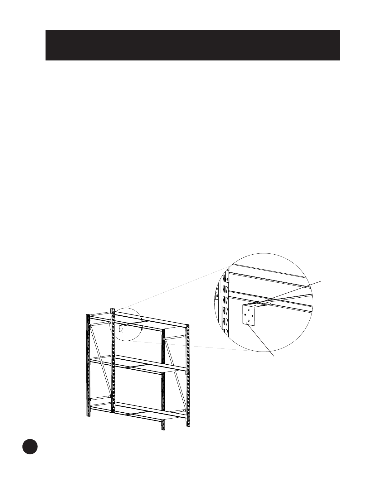
WALL MOUNTING BRACKET
To install the Wall Mount Bracket (Figure 9):
1. Remove the wall mount bracket (Part F) from the box and place to the side until the rack
assembly is complete.
2. Take the top U-shaped portion of the bracket and apply it to the bottom of the shelf (this should
be the very top shelf of the rack).
3. Align the hole in the bracket with the load strap hole located at the bottom center of the shelf beam.
4. Using the same nut and carriage bolt that’s holding the load strap in place, connect the bracket to
the shelf beam.
5. The bracket has two adjustable slots that allow you to adjust the L-shaped portion of the bracket
against the wall.
6. After the L-shaped portion of the bracket is adjusted against the wall, it’s recommended to screw
the bracket into a stud located within the wall rather than wallboard only. If there’s no option to
screw into a stud, wall anchors should be used when mounting into the wallboard.
Note: Wall mounting screws and anchors are included with the Stout Rack; however, different wall
materials require different types of fasteners. Use fasteners suitable for the walls in your home. If
you are uncertain about what type of fasteners to use, please contact your local hardware store.
"U" Portion
Fig. 9
A
"L" Portion
8

ASSEMBLING RACKS UPWARD:
1. When stacking racks on top of each other the assembly process is the same, however when assembling a next tier
of uprights the use of the stacking bracket, (M) is needed.
2. Assemble the upright as shown in steps 1 thru 10 on page 3.
3. Take one of the assembled uprights and place it on top of an already fully assembled bottom rack. The use of the
plastic cap, (D) should not be used between the upright beams and needs to be removed.
4. Take the stacking bracket and apply to the upright beam making sure to engage the tabs into the top and bottom
upright beams.
5. Apply stacking brackets, (M) to ALL 4 uprights before assembling any shelf beam on the top rack.
6. After the brackets are in position, insert the locking pin, (G) into the holes provided.
7. Assemble the remaining shelves in the desired position.
8. Again the use of a wall mounting bracket (F) is needed for both racks after assembly is complete.
Fig. 10
Locking Pin Holes
G
99

LIMITED WARRANTY
J.HANLON™ Storage Racks are backed by a One Year Warranty through JS
Products. This warranty covers manufacturer defects and workmanship. The
warranty excludes misuse or abuse and normal wear and tear.
Work safely with tools by wearing
safety goggles.
PRINTED IN CHINA
10
JS PRODUCTS | 6445 MONTESSOURI STREET | LAS VEGAS, NV 89113
800.255.7011 | FAX: 775.898.8773 | WWW.JHANLONSTORAGE.COM
 Loading...