

Page 1

Digital Video Recorder
Manual
Version 1.1.0
JF TECH(Co.,Ltd)
Page 2
Safety Precautions
The purpose of this content is to ensure that users use the product correctly to avoid danger
or damage to property. Before using this product, please read this instruction manual carefully
and retain it for future reference.
As shown below, precautions are divided into "WARNING" and "CAUTION" in two parts:
WARNING: ignoring warnings could result in death or serious injury.
Note: ignore the precautions could result in injury or property damage.
WARNING:
In the product installation, you must strictly follow all electrical safety procedures and the
use of regional countries.
1. In the product installation, you must strictly follow all electrical safety procedures and
the use of regional countries.
2. Please use regular factory supplied power adapter.
3. Do not place more than one DVR connected to the same power (adapter overload may
produce excessive heat or cause a fire).
4. When wiring, dismantling and other operations, please be sure do not connect the
power.
5. The smoke phenomenon recorder, or produce odor, or noise, turn off the power
immediately and unplug the power cord and contact your dealer or service center.
6. If the device is not working properly, contact your dealer or the nearest service center,
do not disassemble or modify the device in any way. (On the issue of unauthorized
modification or repair resulting from the Company is not liable).
CAUTION:
1. Do not make objects fall to vigorously shake the device or equipment, and to place the
device away from the presence of magnetic interference. Avoid installing the surface
vibration or vulnerable areas (ignore this may damage the device).
2. Installed may not be exposed to rain or very humid areas.
WARNING
Precautions to prevent the potential
danger of death or serious injury。
CAUTION
Precautions to prevent the potential
danger of injury or property damage.
Thanks for purchasing our products, if you have any questions or need, please feel free to
contact us.
The manual is the DVR product manuals, support functions due to the different models differ,
please prevail in kind.
This manual is intended for you as an operating system and programming reference tool. You
can find information about the features and commands in this manual, as well as a detailed menu
tree and Quick Start Guide. Installation section provides the setup and installation of network dome
camera information needed. Before installing and using the system to fully understand the
information in this manual.
This manual may contain technical inaccuracies, or does not match the product features and
operations, or typographical errors. We will update the contents of this manual is based on product
enhancements, and will regularly update the product or process improvements or described in this
manual. Updated content will be added in the new version, without notice.
Page 3

3. Avoid placing the device in direct sunlight place, or poorly ventilated location, or near a
heat source such as a heater or heating, etc. (ignore this may cause a fire hazard).
4. In order to avoid damage to the DVR, do not have the DVR set up in smoke or steam, the
temperature is too high or there is a lot of dust in the workplace.
5. When cleaning, use a soft cloth to wipe off the dirt on the housing. When cleaning up
dirt, dry cloth should be cleaned when the dirt is hard to remove, use neutral detergent
gently wipe clean, do not use alkaline detergents. If there is sticky dust on the lens, use
a special lens paper wipes.
Page 4

Contents
1. Introduction .............................................................................................................................. 5
1.1 Product Brief ................................................................................................................. 5
1.2 Main Functions .............................................................................................................. 5
2. Unpacking and cable connection .............................................................................................. 7
2.1 Unpacking...................................................................................................................... 7
2.2 Hard disk installation ..................................................................................................... 7
2.3 Shelf Installation ............................................................................................................ 8
2.4 Front Panel .................................................................................................................... 8
2.5 Rear panel ..................................................................................................................... 9
2.6 Audio & Video input and output connections ............................................................ 10
2.7 Alarm input and output connections .......................................................................... 11
2.8 Connect Line 485 ......................................................................................................... 13
3. Basic Operations ..................................................................................................................... 15
3.1 Turn on ........................................................................................................................ 15
3.2 Turn off ........................................................................................................................ 15
3.3 System Login ............................................................................................................... 15
3.4 Preview ........................................................................................................................ 16
3.5 Desktop shortcut menu ............................................................................................... 16
4. Main menu .............................................................................................................................. 31
4.1 Main menu navigation ................................................................................................ 31
4.2 Record function ........................................................................................................... 32
4.3 Event function ............................................................................................................. 34
4.4 System settings ............................................................................................................ 40
4.5 Advanced ..................................................................................................................... 57
4.6 System Info .................................................................................................................. 67
4.7 Shut down system ....................................................................................................... 70
5. Remote Cloud Operating Instructions ..................................................................................... 71
5.1 Cloud surveillance ....................................................................................................... 71
6. FAQ and maintenance ............................................................................................................. 74
6.1 FAQ .............................................................................................................................. 74
6.2 Maintenance ............................................................................................................... 78
Appendix Ⅰ Remote controller operation ............................................................................... 80
Appendix Ⅱ Mouse operation ................................................................................................. 81
Appendix Ⅲ Hard disk capability calculation ........................................................................... 82
Page 5

1. Introduction
1.1 Product Brief
The series Digital Video Recorder (hereinafter referred to as DVR) is designed especially for
security and defense field which is an outstanding digital surveillance product. It introduces
embedded LINUX operating system which is more stable. It introduces standard H.264mp
video compressed format which insures the high quality image, low coding ratio and single
frame playing. It introduces TCP/IP network technology which achieves the strong network
communication ability and telecommunication ability.
This device can be used individually, but also form a powerful security monitoring network,
with professional network video surveillance platform software, which fully reflects its strong
networking and remote monitoring capabilities.
The series DVR are widely used in power systems, telecommunications sector, banking
security, industrial enterprises, intelligent buildings, intelligent community, urban roads,
airports, railway stations and other surveillance applications.
1.2 Main Functions
Real-time surveillance
Spot interface、analog output interface、VGA interface and HDMI interface,surveillance function
through monitor or display.
Storage
Non-working hard disk dormancy processing which is convenient to radiate heat, reduce power
and extend the life-span
Special storage format which insures the data safety
Compression
Real-time compression by individual hard disk which insures the audio and video signal stable
synchronization
Backup
Through SATA interface and USB interface such as USB equipment, removable hard disk and so on
Through net download the files in the hard disk
Playback
Individual real-time video recording as well as searching, playback, network surveillance,
recording check, downloading and so on
Multi-playback mode
Zoom at arbitrary region
Net operating
Real-time monitoring can be carried out remotely via the network (including mobile phone)
Remote PTZ control
Remote video search and real-time playback
Page 6

Alarm linkage
Alarm recording, round robin, the screen prompts, beep, mail, FTP
Communication interface
With RS485 interface, alarm input and PTZ control
With RS232 interface, scalable keyboard connection to the master, and connected to the
computer serial port for system maintenance and upgrades, and matrix control
With standard Ethernet interfaces, network remote access feature
Intelligent operating
Mouse action function
Fast copy and paste operating for the same setting
Page 7
2. Unpacking and cable connection
2.1 Unpacking
When you receive the product:
First, check whether the packaging equipment has obvious damage. Selection of protective
packaging materials during transport can cope with most of the unexpected hit;
Then, remove the device, remove the plastic protective film DVR, check whether there is any
visible damage to the outside;
Finally, open the case, check the front panel data cable, power cable, power supply and
motherboard fan connector is loose.
Front panel and rear panel
Various interfaces on the front panel and the rear panel of the various key functions are
described in detail in the specification;
Please check carefully whether the product model on the front panel with foil products you
ordered the same model;
Label affixed to the rear panel, has a very important significance for our service work, please
protect. In the company's after-sales service when you contact us, you will need to provide
the model and serial number to order the label.
Check
In addition to checking for any obvious signs of damage, but please pay attention to check
the front panel data cable, power cable and the motherboard connection is loose.
2.2 Hard disk installation
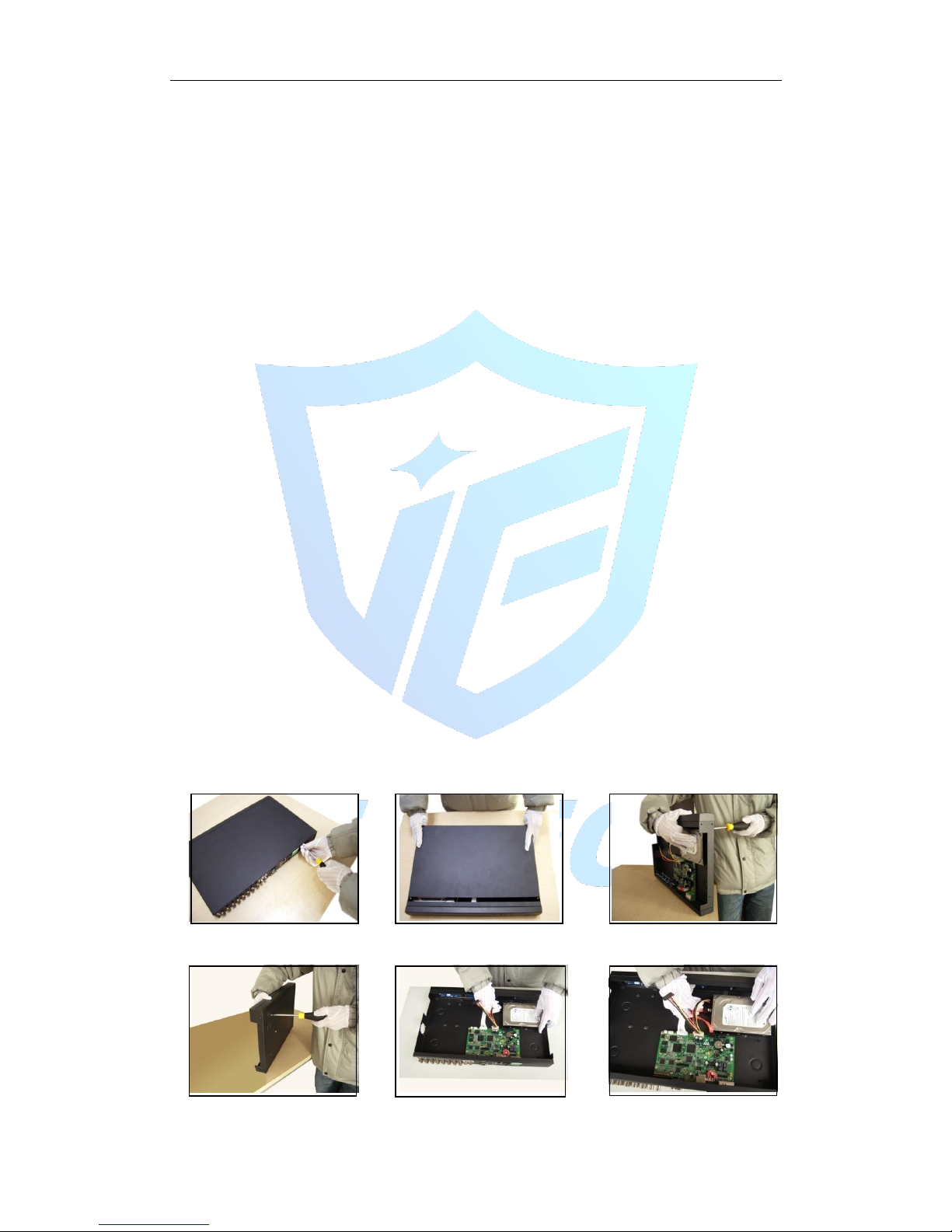
When you use, first install the hard drive, the machine can install two hard drives inside (capacity
no limit).
①disassemble the screw ②disassemble the cover ③fix the screw of hard disk
④fix the screw of hard disk ⑤connect the data wire ⑥connect the power wire
Page 8
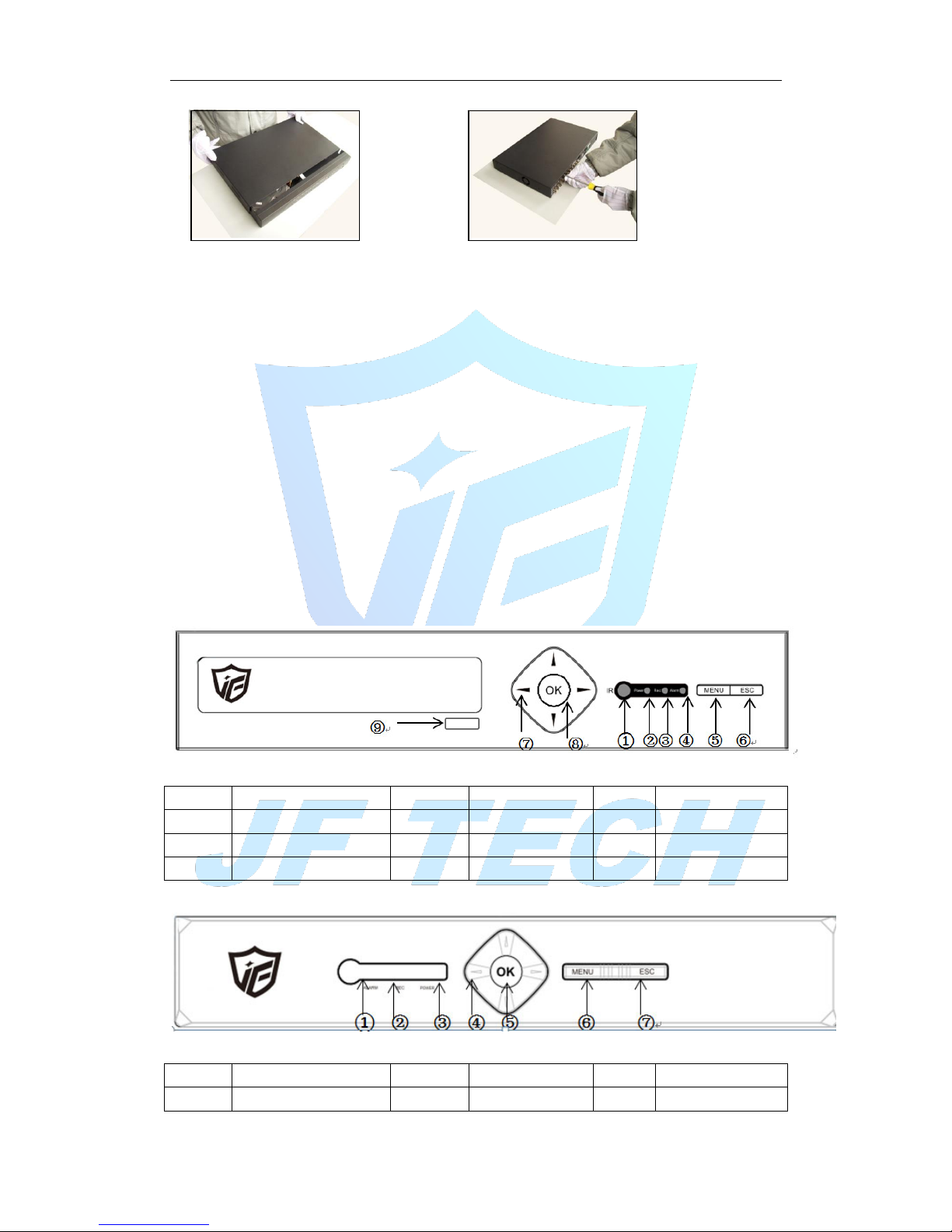
⑦cover the machine ⑧fix the cover
2.3 Shelf Installation
This product chassis specification is standard 1u, so it can be installed in the standard shelf.
Installation steps and attention items:
1. Make sure the temperature in the room lower then 35℃ (95°f).
2. Keep the equipment has 15cm (6 inches) space around in order to air's circulation.
3. From bottom to shelf installation.
4. When multiple components install in the frame,please take preventive measures to avoid
power socket overload.
2.4 Front Panel
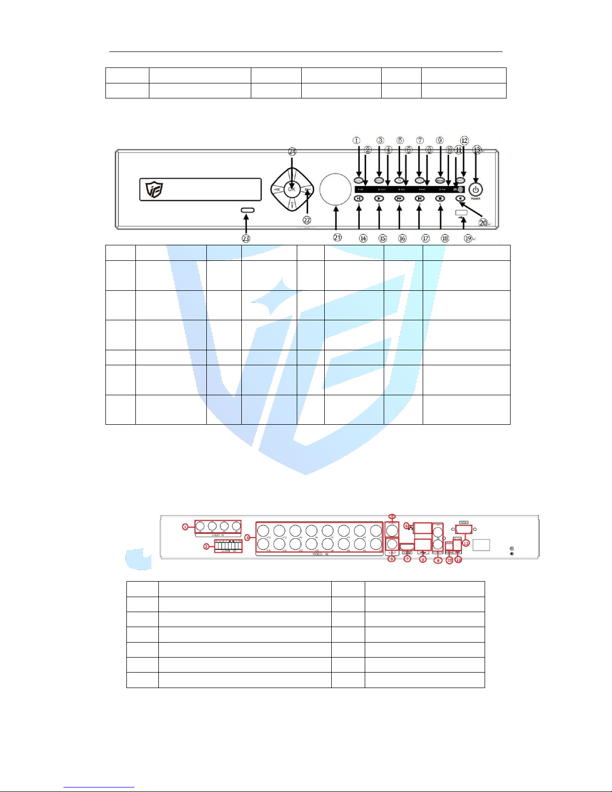
2.4.1 B series
NO.
Function
NO.
Function
NO.
Function
1
IR 2 Power
3
Record
4
Alarm
5
Menu
6
ESC 7 Direction
8
OK 9 CD-ROM
2.4.2 T Series
NO.
Function
NO.
Function
NO.
Function
1
Alarm Indicator
2
Record Indicator
3
Power Indicator
Page 9
4
Direction
5
OK 6 Menu
7
ESC
2.4.3 K Series/F Series
NO.
Function
NO.
Function
NO.
Function
NO.
Function
1
Exit 2 HDD
indicator
3
Mode
4
Record indicator
5
Rec 6 Alarm
indicator
7
PTZ Control
8
Shift indicator
9
Menu
10
Power
indicator
11
IR Receiver
12
Shift
13
Power Switch
14
Next file
15
Play
16
Fast Play
17
Last file
18
Stop
19
USB
interface
20
Null
21
Jog wheel
22
Direction
23
CD-ROM
switch
24
OK
2.5 Rear panel
2.5.1 rear panel interface diagram
16ch as example
No.
Function
No.
Function
1
AUDIO INPUT
7
HDMI
2
ALARM INPUT
8
USB 3 VIDEO INPUT
9
AUDIO INPUT
4
VIDEO OUTPUT
10
RS485
5
AUDIO OUTPUT
11
DC/12V
6
NETWORK PORT
12
VGA
4/8ch DVR:
Page 10
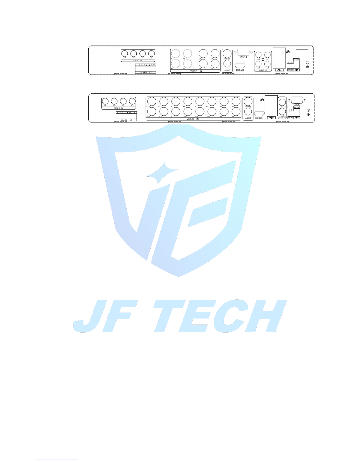
16ch DVR:
2.6 Audio & Video input and output connections
2.6.1 video input
DVR video input port to the BNC input signal requirements: PAL / NTSC BNC (1.0VP-P,
75Ω).
Video signal should comply with national standards, a higher signal to noise ratio, low
distortion, low interference; image must be clear, invisible change, real and natural
color, brightness is appropriate.
Ensure stable and reliable camera signal:
Cameras should be installed in a suitable location, to avoid backlighting, low light
conditions, or the use of good results backlight compensation cameras, low-light
cameras.
Camera and DVR power supply should be common ground, and reliable, in order to
ensure the normal operation of the camera.
Ensure stable and reliable transmission line:
Using high-quality, shielded coaxial good video, and based on the transmission distance
to choose the right model. If the distance is too far, should be based on the specific
circumstances, the use of twisted pair, add video compensation equipment, fiber optic
transmission and other ways to ensure signal quality.
Video signal line should avoid strong electromagnetic interference to other equipment
and lines, especially should avoid high-voltage current string into.
Lugs ensure good contact:
Signal and shield lines should be firm, well-connected, avoid Weld, lap welding, to
avoid oxidation.
2.6.2 Select and connect the video output device
Video output is divided into PAL / NTSC BNC (1.0VP-P, 75Ω) output and VGA output
(VGA is optional)
Choose to use computer to replace the monitor should pay attention to the following
questions:
1. Do not keep long boot state to extend the life of the equipment;
2. regular degaussing, which will help maintain the normal operation of the display;
3. Away from strong electromagnetic interference devices.
Use TV as a video output device is an unreliable alternative. It also requires minimizing
Page 11

the use of time and strictly controls the interference power caused by neighboring
devices. Inferior TV leakage risks may cause damage to other equipment.
2.6.3 SDI video output
Some models support coding for 1080P (720P) SDI video.
2.6.4 Audio input
BNC connector (only one to support intercom function)
Audio input impedance is high, and therefore must be used active pickups.
Similar to the video input audio transmission requires line to avoid interference, avoid
Weld, poor contact, and special attention to prevent a string of high-voltage current
into.
2.6.5 Audio output
Audio output signal parameters is generally greater than 200mv 1KΩ (BNC), you can
directly connect the low impedance headphones, powered speakers or other sound
through power amplifier output devices. In the case of external speakers and
microphone cannot be achieved spatial isolation, it is easy to produce output howling
phenomenon. At this point the measures to be taken are:
1. The use of directional better pickups;
2. Adjust speaker volume, making it lower than the threshold to produce the whistle;
3. Multi-use environment using sound-absorbing materials decoration, reduce the
reflection of the sound, improve the acoustic environment;
4. Adjust the layout of pickups and speakers, but also can reduce the occurrence of
howling situations.
2.7 Alarm input and output connections
Before connecting the device, please note the following:
* Note: Some Series devices without alarm input and output functions.
2.7.1 Alarm Input
Alarm input is grounding alarm input;
Alarm input requirements for ground voltage signal;
When the alarm is connected to two DVRs or simultaneously access the DVR or DVR
and other devices, need to be isolated by relay.
2.7.2 Alarm Output
DVR alarm output cannot be connected power load (no more than 1A), should
constitute the output loop current is too large to prevent damage to the relay. Require
the use of high-power load contactors isolation.
2.7.3 PTZ decoder connected
A. must do PTZ decoder and DVR common ground, otherwise there may be
common-mode voltage will lead to control PTZ. Recommended to use shielded twisted
pair with shielding for common ground connection;
B. prevent high voltage in series, rational layout, good lightning protection measures
C. to be incorporated into the 120 ohm resistor in the remote reduced reflection, to
ensure signal quality;
D. DVR 485 AB line cannot be connected with other 485 output;
Page 12
E. AB line voltage between the decoder requires less than 5V.
2.7.4 Front-end device requires grounding
Poor grounding may cause the chip to burn.
2.7.5 Any type of alarm input
The alarm output unit interface is a normally open type.
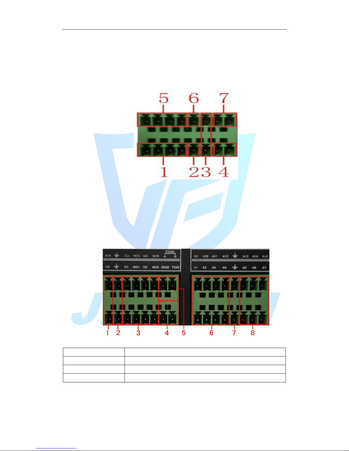
8 external alarm interface schematic:
(1) Alarm input 1,2,3,4
(2) Ground
(3) RS232 serial interface to send and receive
(4) RS485 interface
(5) alarm inputs 5,6,7,8
(6) Ground
(7) alarm output
16 External alarm interface schematic:
① ⑥⑧ alarm input ②⑦ ground ③ alarm output RS485④RS232
Parameters
Meaning
G
GND
R、T
Send and receive serial interface
A、B
485 communication interface
2.7.6 Alarm Input Port Description
8/16 channel alarm input, input type limitation (can be normally open or normally
closed);
Page 13
Alarm detector ground terminal (GND) and com-side parallel (alarm detectors by
external power supply);
Ground terminal and the ground terminal DVR alarm detector and then;
NC end alarm detector is connected to DVR alarm input terminal (ALARM);
When using an external power supply required for alarm equipment and DVR common
ground.
2.7.7 Alarm Output Port Description
2 channels alarm output (normally open contact), the need for external alarm device
power supply;
To avoid overload and damage the host, please refer to the relay relevant parameters
when connecting relay relevant parameters Annex.
2.7.8 Alarm output Relay terminal parameters
Model: JRC-27F
Shock material
Silver
Ratings
(Resistive load)
Rated switching capacity
30VDC 2A, 125VAC 1A
Maximum switching power
125VA 160W
Maximum switching voltage
250VAC, 220VDC
Maximum switching current
1A
Insulation
between the same polarity Contacts
1000VAC 1 minute
between different polarity Contacts
1000VAC 1 minute
Between coil and contacts
1000VAC 1 minute
Surge voltage
between the same polarity Contacts
1500VAC (10×160us)
Opening time
3ms max
Turn-off time
3ms max
Lifetime
Machinery
50×106 MIN(3Hz)
Electrical
200×103 MIN (0.5Hz)
Work environment
-40~+70℃
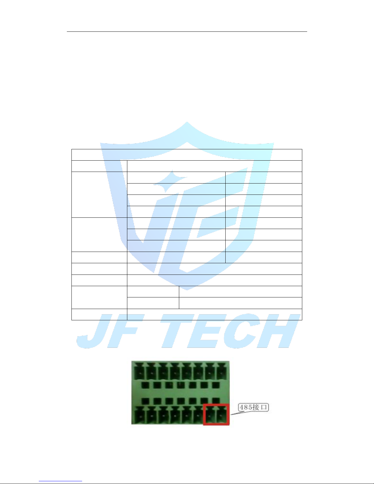
2.8 Connect Line 485
8 external alarm 485 Schematic
Page 14
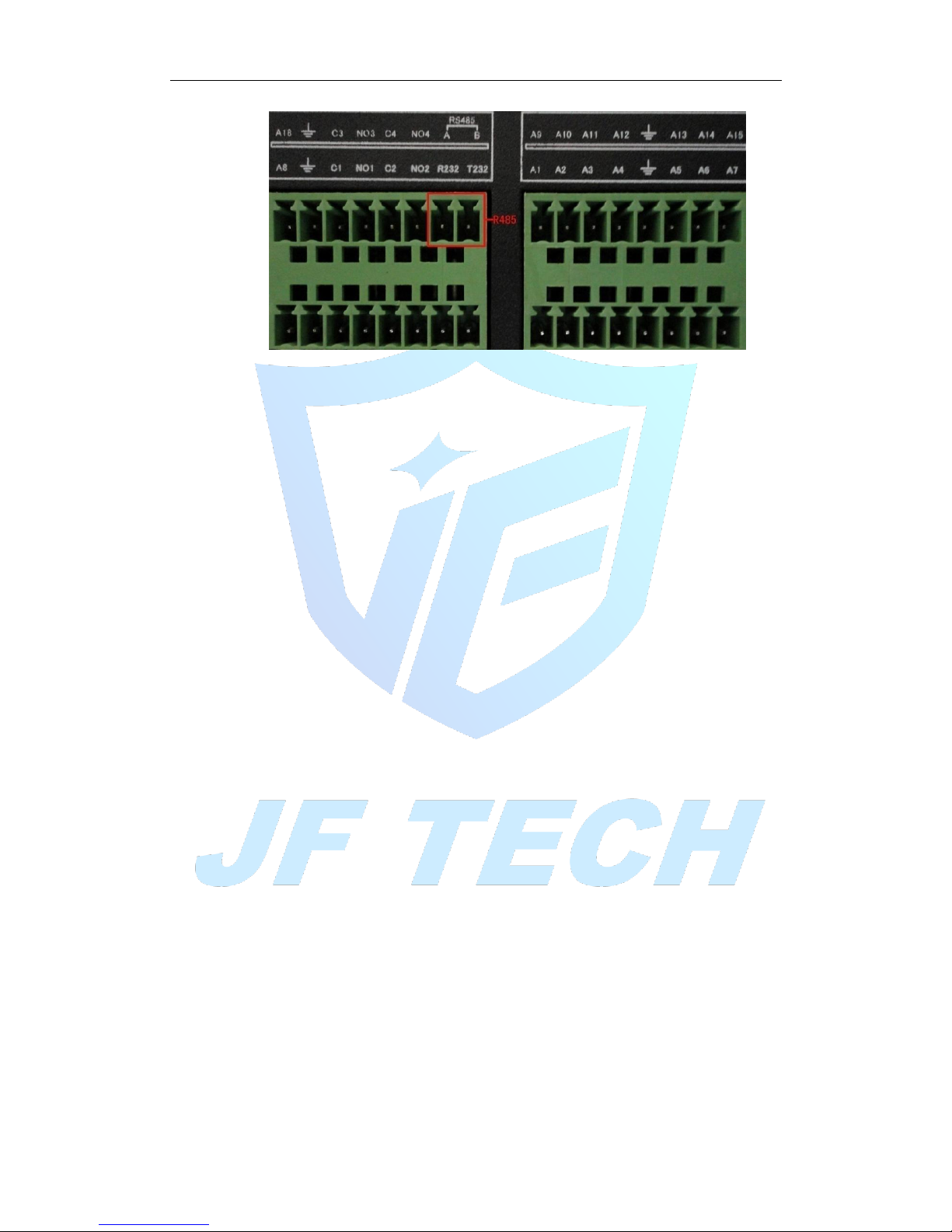
16 external alarm 485 Schematic
Page 15

3. Basic Operations
Note: The button is grayed means did not support.
3.1 Turn on
Plug the power supply and turn on the power supply switch. Power supply indicator light
shining indicates turning on the video recorder. After the startup you will hear a beep. The
default setting of video output is multiple-window output mode. If the startup time is within
the video setting time, the timing video recording function will start up automatically. Then
the video indicator light of corresponding channel is shining and the DVR is working
normally.
Note:
1. Make sure that the input voltage corresponds with the switch of the DVR power supply.
Power supply demands: 220V±10% /50Hz.
Suggest using the UPS to protect the power supply under allowable conditions.
3.2 Turn off
There are two methods to turn off the DVR. Right click mouse to get a desktop shortcut
menu ,then choose Logout option is called soft switch. Pressing the power supply switch is
called hard switch.
Illumination:
1、Auto resume after power failure
If the DVR is shut down abnormally, it can automatically backup video and resume previous
working status after power failure.
2、Replace the hard disk
Before replacing the hard disk, the power supply switch in the real panel must be turned off.
3、Replace the battery
Before replacing the battery, the setting information must be saved and the power supply
switch in the real panel must be turned off. The DVR uses button battery. The system time
must be checked regularly. If the time is not correct you must replace the battery, we
recommend replacing the battery every year and using the same battery type.
Note: The setting information must be saved before replacing the battery otherwise
information will lose.
3.3 System Login
When the DVR boots up, the user must login and the system provides the corresponding
functions with the user purview. There are two user settings. The names are admin, and
default and these names have no password. Admin is the super user purview; default’s
Page 16
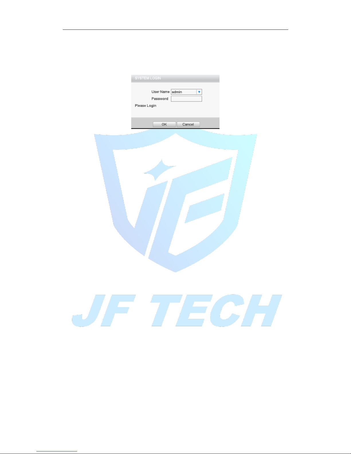
permissions are preview and video playback. User password can be revised, while their
permissions can’t be revised; user default is the default login user whose permission can be
revised but not its password.
Figure 3.1 Login
Password protection: If the password is continuous wrong three times, the alarm will start.
If the password is continuous wrong five times, the account will be locked. (Through
reboot or after half an hour, the account will be unlocked automatically).
For your system security, please modify your password after first login.
3.4 Preview
You can right click mouse to choose the switch between the windows.
The system date, time and channel name are shown in each viewing window. The
surveillance video and the alarm status are shown in each window.
3.5 Desktop shortcut menu
In preview mode you can right click mouse to get a desktop shortcut menu, as the Figure 3.2
shows. The menu includes: main menu, Guide, Quick Set, Record Mode, playback, PTZ
control, Coaxial Control, TVI&AHD, High Speed PTZ, color Setting, Output adjust, Logout,
View.
Page 17
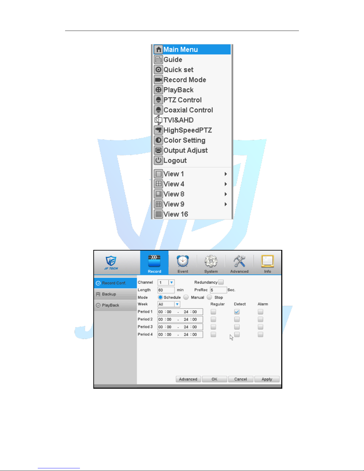
Figure 3.2 shortcut menu
3.5.1 Main menu
When you login, the system main menu is shown as below.
Figure 3.3 main menu
3.5.2 Boot wizard
Provide fast setup to wizard configuration parameters. Including boot wizard,
two-dimensional code and digital channel configuration wizard, click “Next” to enter
Page 18
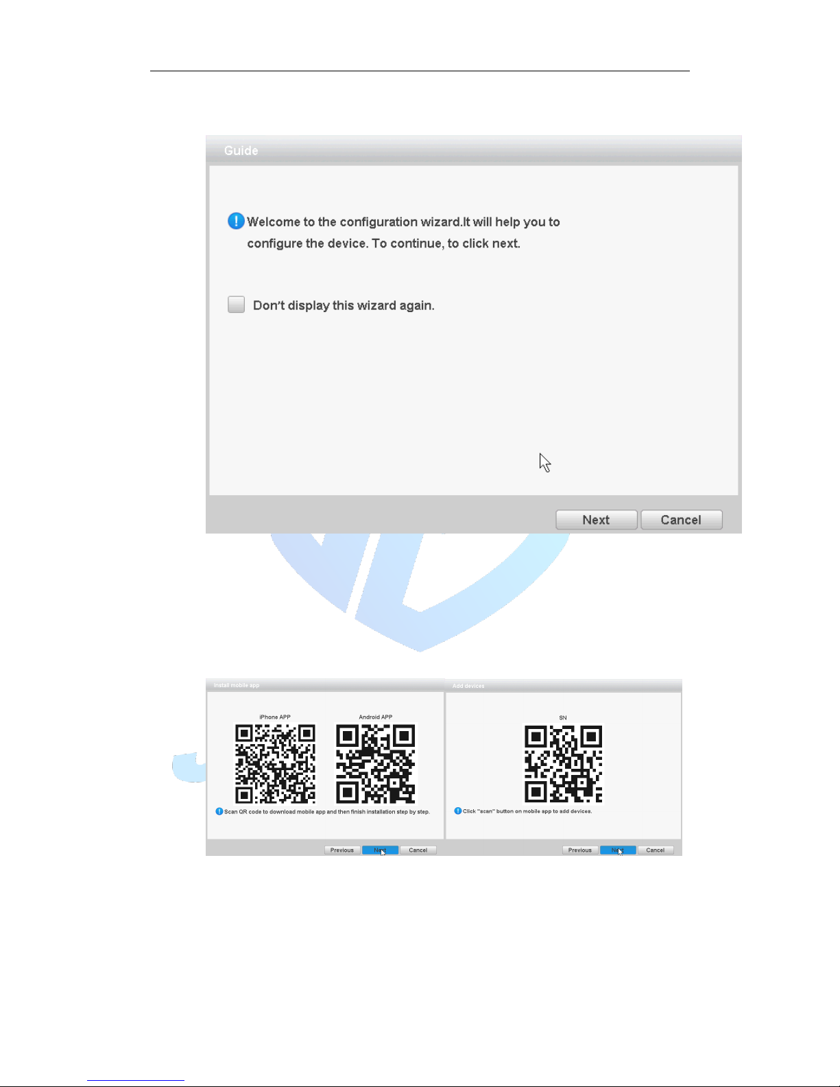
the digital channel configuration wizard.
Boot wizard:
Figure 3.4 Boot wizard interface
[Do not Display] select the highlighted ■ expressed after reboot, no longer
automatically pop up boot wizard.
[Next] enter the digital channel configuration wizard interface.
[Cancel] to save the settings and exit this screen wizard interface.
QR Code
Figure 3.5 QR code interface
Mode selection:
Page 19
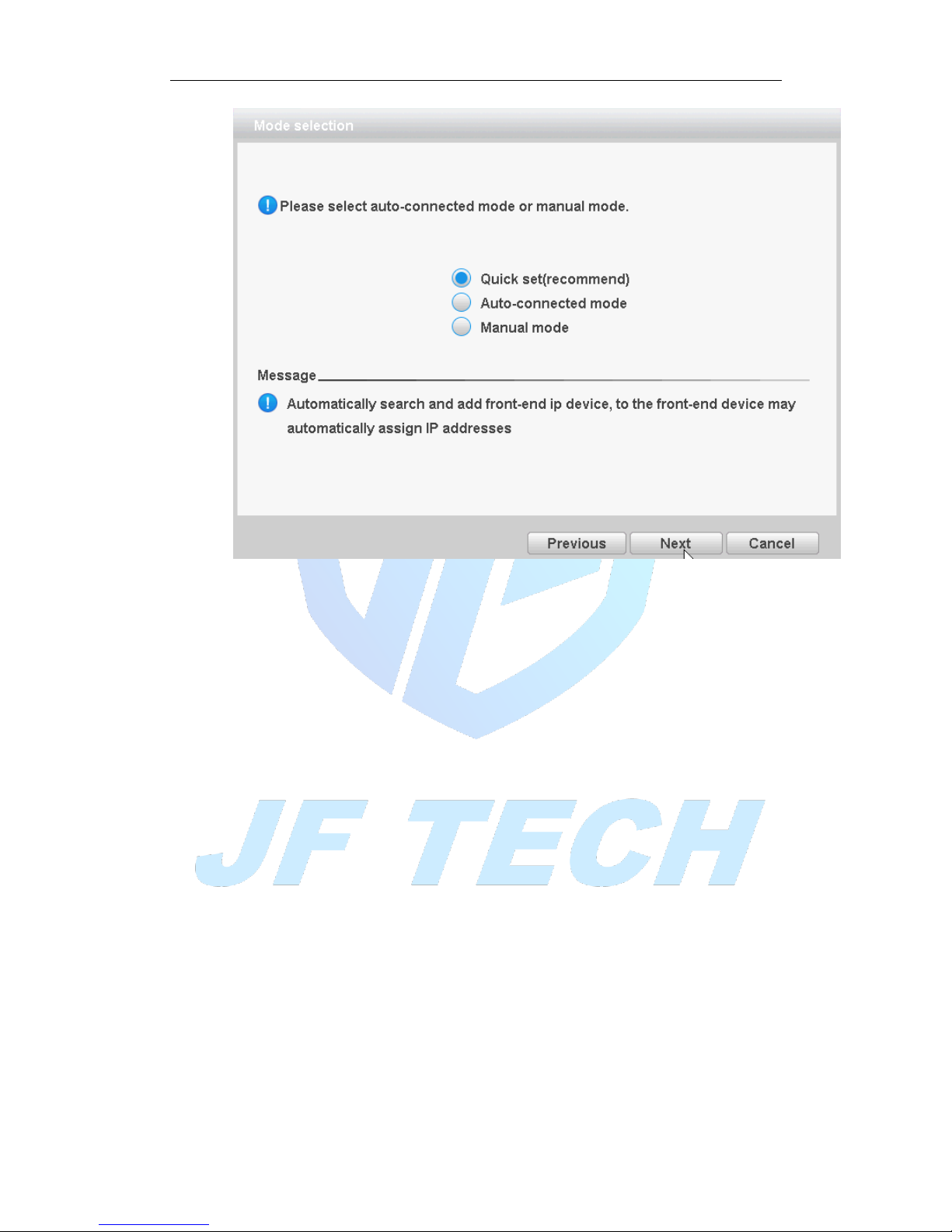
Figure 3.6 mode selection
Click “Next” on the figure 3.4, will pop up APP and SN QR code, and then click next to
pop up mode selection. Select the manual mode to enter the digital channel
configuration wizard which as shown in Figure 3.7, you can set shortcuts for digital
channels; select ad hoc network mode, the device will automatically modify the LAN IP
address of the front-end equipment, digital channels and front-end devices connect
automatically.
NOTE: If you have the front-end cannot be modified under the networking mode is
recommended since set up a separate LAN.
Digital Channel Configuration Wizard:
NOTE: After using this function, the parameters in the configuration of all digital
channels will be updated, please caution.
Page 20
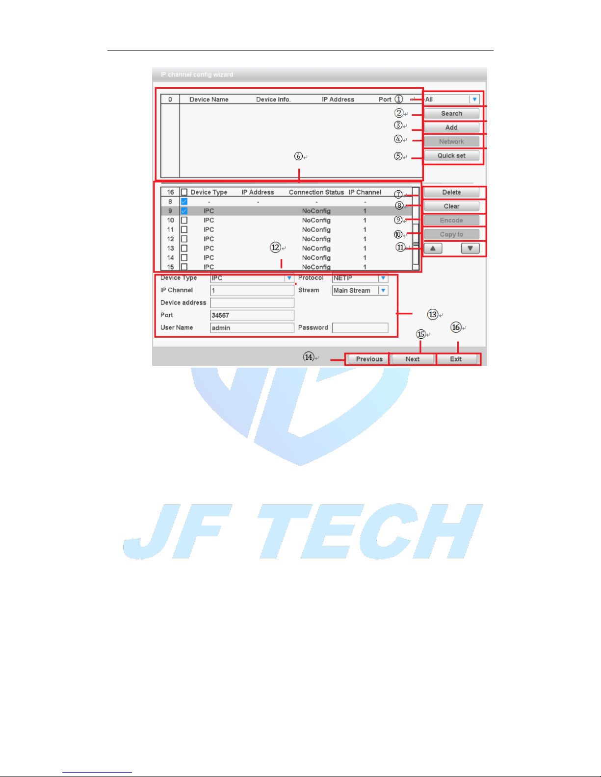
Figure 3.7 Digital Channel Configuration Wizards
Label meanings:
1. Search protocol selection
Includes three search methods, respectively NETIP, ONVIF, ALL
2. Search
Search device
3. Add
Add device
4. Network Settings
The device can be set remotely channel, user name, password; click the Network
Settings button, you can set the network of the device, including IP, subnet mask,
default gateway (ONVIF protocol devices cannot make network settings).
Page 21
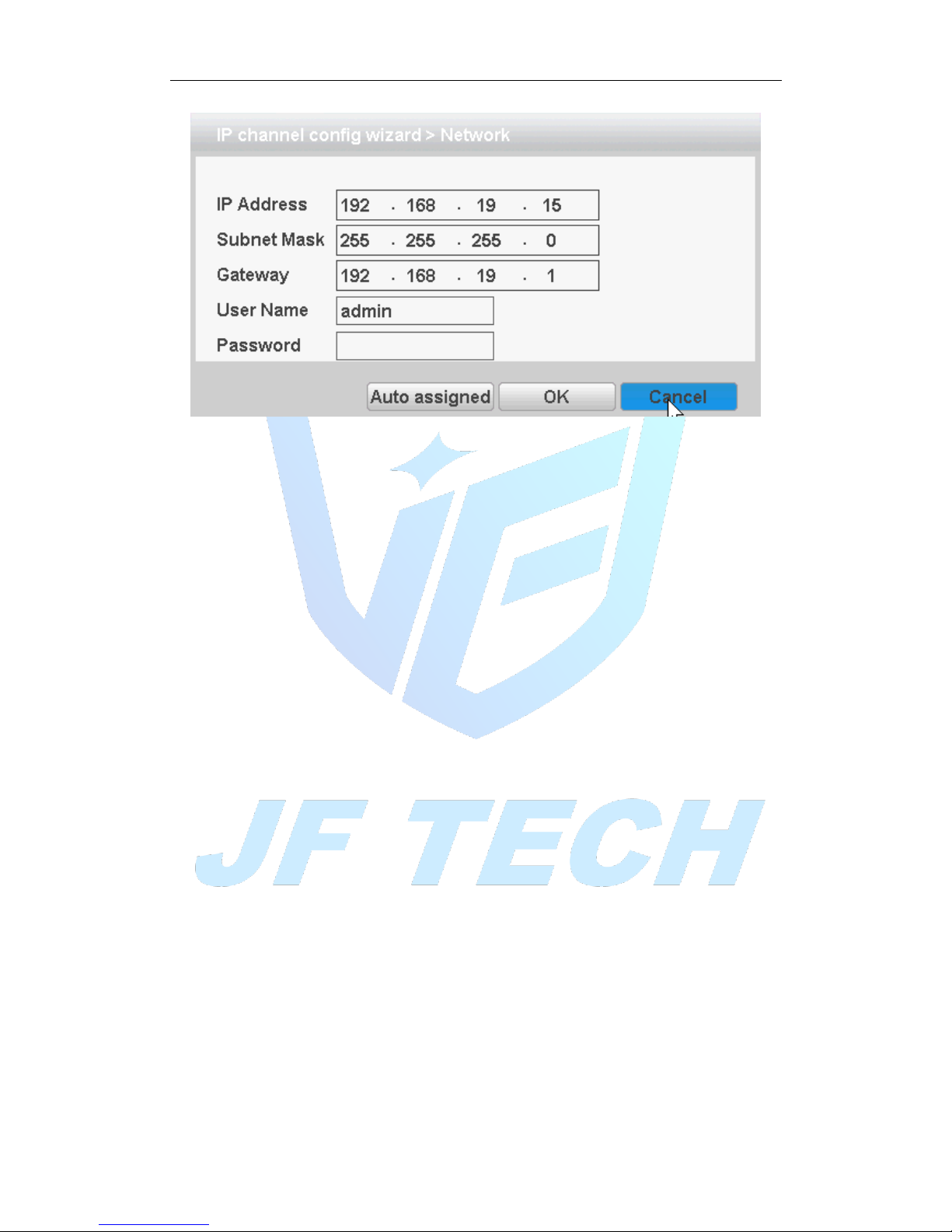
Figure 3.8 network settings
5. Hotkey settings
Configure all channels by one key.
6. Equipment list display area
This area displays the discovered devices.
7. Delete
Select the device has been configured, click Delete, you can delete the device
8. Clear
Clear all configured channels
9. encoding settings
You can set the front end configured coding
10. Copy to
Some information of selected channels can be copied to other channels, such as user
name, password, and other device information, as shown below:
Page 22
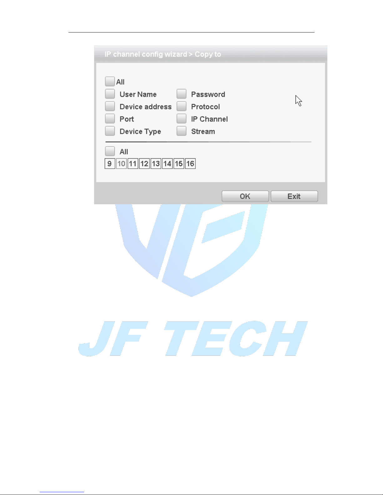
Figure 3.9 Copy to
11. Up and down keys
Click the device in the list, click up and down buttons to move the device up and down.
12. Configuration Status
Configuration status of each channel, including not configured, connected, not online
13. configuration front-end information
The information of the front-end configured, user name, password can be set in this
area.
14. Back
Return to the previous screen and that is the boot wizard interface.
15. completed
Add the selected device to the appropriate digital channels, and then enable the
channel; the remaining non-selected digital channel is not enabled.
16. Exit
Return to the preview screen.
3.5.3 Playback
There are two methods for you to play the video files in the hard disk. Through shortcut
menu or form Main menu>Record->Playback.
Note: The hard disk that saves the video files must be set as read-write or read-only
state.
Page 23
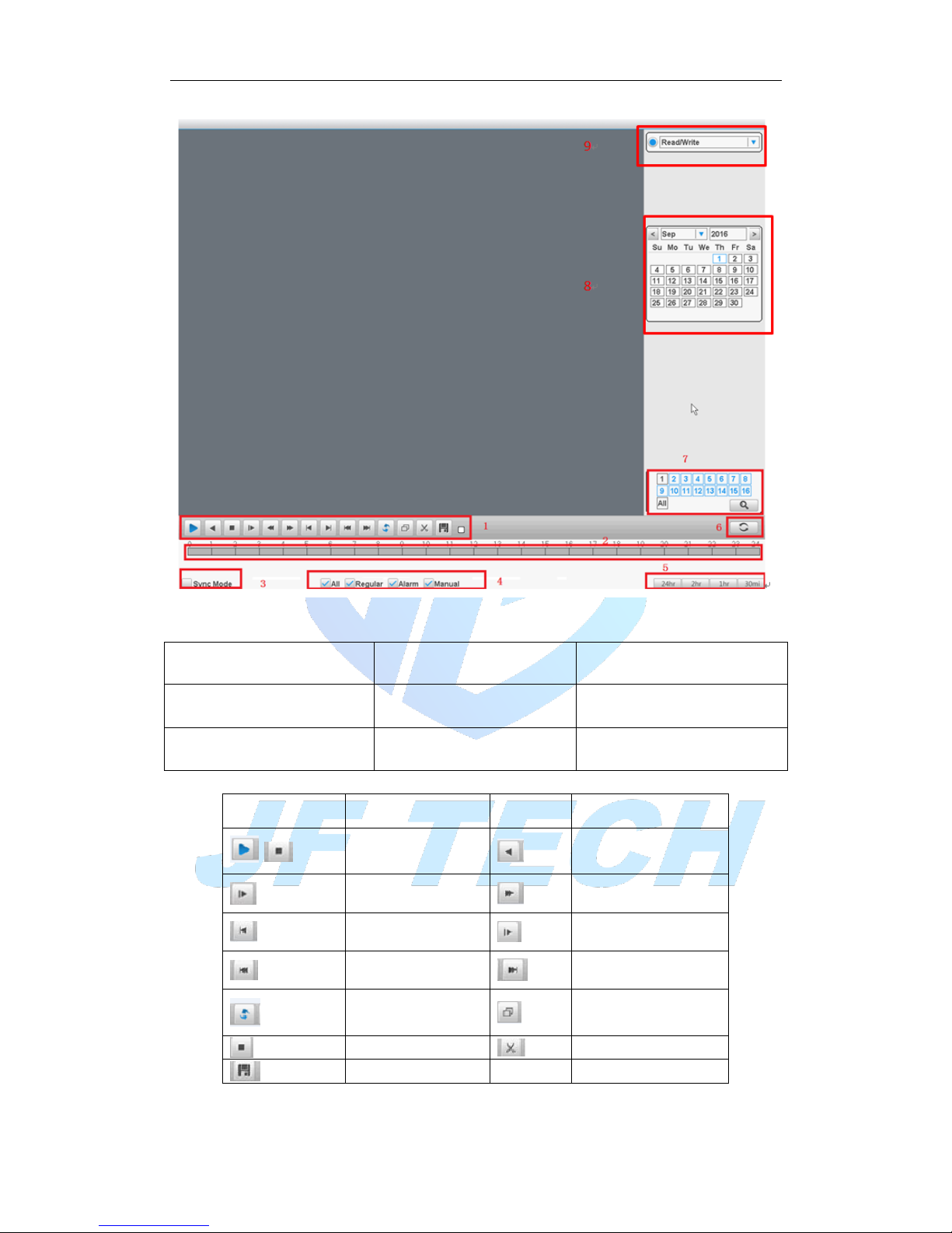
Figure 3.10 Playback
1. Playback control
2. Time display
3. Synchronous
4. Video type
5.Time schedule options
6.search by time/switch mode
7.Channel Selection
8.Date selection
9. Storage device selection
【Playback control】See detail in below chart:
Button
Function
Button
Function
/
Play/Pause
Backward play
Slow play
Fast Rewind
Previous frame
Next frame
Previous file
Next file
Loop
Full screen
Edit Start / End Clip
Clip video backup
Table 3.2 Playback control key
Page 24
Note: play under frame by frame, the playback status should be paused firstly.
【Operation tips】show function of the key that cursor placed.
Special functions:
Local zoom:When the system is in single-window full-screen playback mode, you can
drag your mouse in the screen to select a section and then left click mouse to realize
local zoom. You can right click mouse to exit.
Note: When current resolution of the channel is over Max resolution, to playback this
channel, will show a Red “X”.
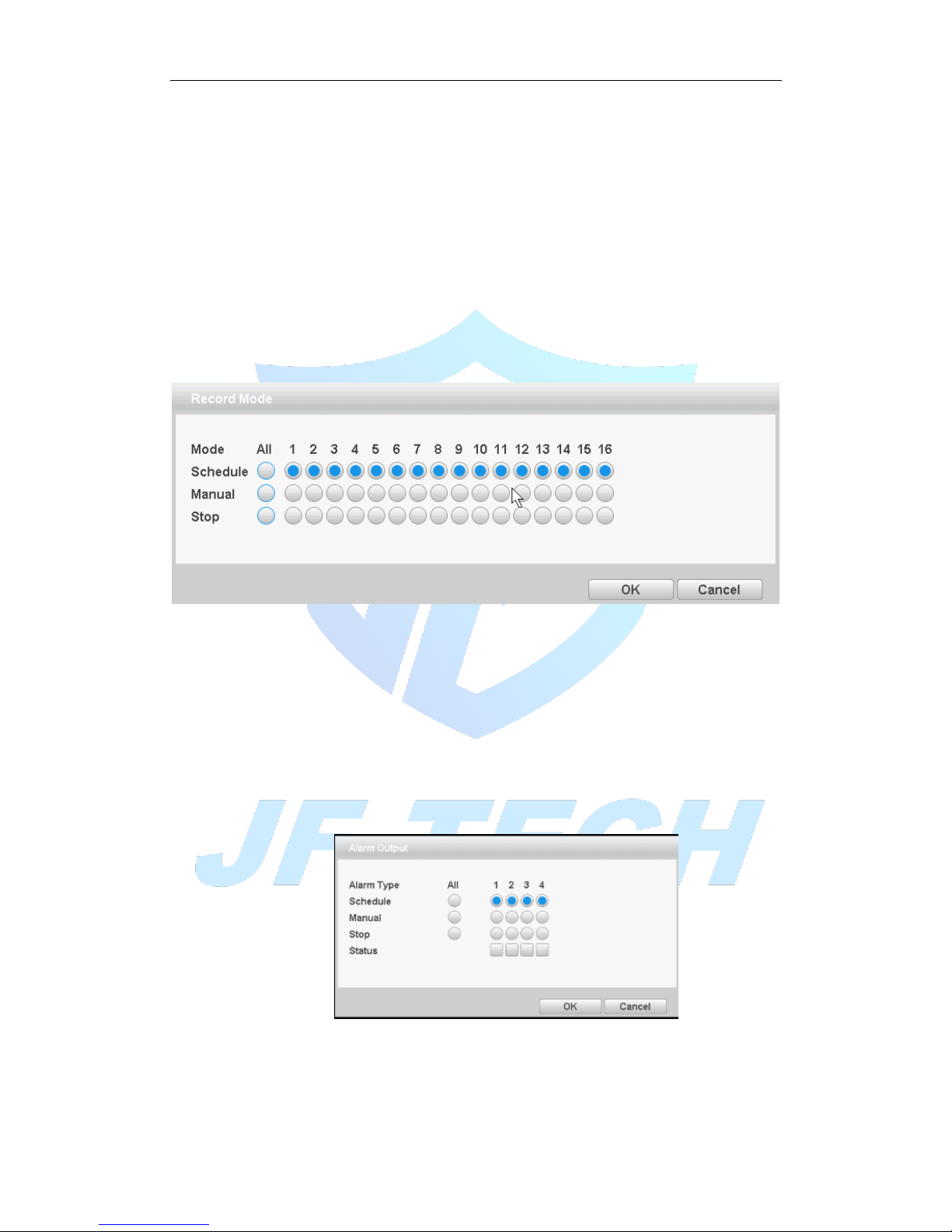
3.5.4 Record controls
Please check current channel status: “○” means it is not in recording status, “●” means
it is in recording status.
You can use desktop shortcut menu to enter the recording control interface.
Figure 3.11record control
【Schedule】Record according to the configuration.
【Manual】Click the all button and the according channel is recording no matter the
channel in any state.
【Stop】Click the stop button and the according channel stops recording no matter the
channel in any state.
3.5.5 Alarm output
Control each channel alarm output state, ■ means that the channel has alarm output.
You can use desktop shortcut menu to enter the alarm output interface.
Figure 3.12 alarm output
[Schedule] according to the configuration information, and outputs an alarm signal;
[Manual] no matter what state, select "Manual" button, the corresponding channel
output alarm signal;
Page 25
[Stop] regardless of what state, select "Close" button, the channel will not output an
alarm signal
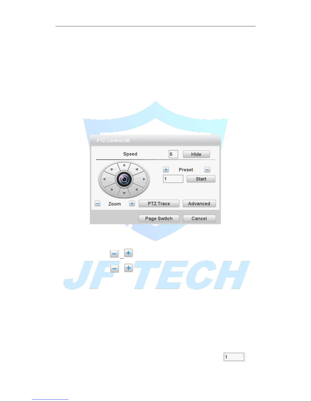
3.5.6 PTZ control
*PTZ control is a little different between hybrid mode & full digital mode:
Digital channel – the digital channel need link PTZ, the remote device should connect
with PTZ and with protocol correctly set also.
The functions include: PTZ direction control, step, zoom, focus, iris, and setup
operation, patrol between spots, trail patrol, boundary scan, assistant switch, light switch,
level rotation and so on.
Note:
1. Decoder A (B) line connects with NVR A (B) line. The connection is right.
2. [main menu]> > [system] > [PTZ Config] to set the PTZ parameters.
3. The PTZ functions are decided by the PTZ protocols.
Figure 3.13 PTZ settings
【Speed】Set the PTZ rotation range. Default range: 1 ~ 8.
【Zoom】Click / button to adjust the zoom multiple of the camera.
【Preset】Click / button calls the preset points, PTZ automatically turns to
the setting position.
【Hide】Current interface will be temporarily hidden after click it.
【Direction control】Control the PTZ rotation. 8 directions control is supportive. (4
directions in Front panel is supportive)
【Advanced】Full-screen show channel image. Left press mouse and control PTZ to
rotate orientation. Left press mouse and then rotate the mouse to adjust the zoom
multiple of the camera.
【Page switch】Switch between different pages.
【Preset】
1.Increase the preset point
By the arrow keys to adjust the good Yuntai location,Enter a number in ,
Page 26
then click on the button, you can add a preset point.
2.Deleting preset
Enter a number in,Then click on the delete preset.
3.Preset
Enter a number in ,Then click on the ,head will rotate to the
preset position.
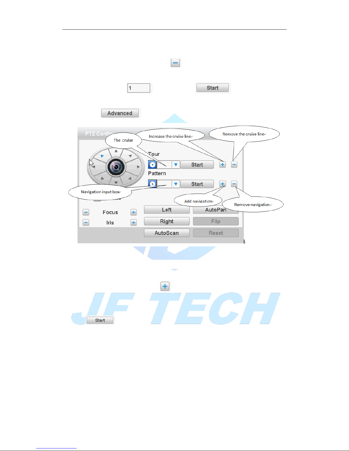
click on the Enter a new operation page as shown below
Figure 3.14 Advanced function
【Point between the cruise】
1.Increase the cruise line
Enter a number in,Click the key point between the cruise enter the settings page
increase cruise line .
Can preset point in the input box, enter preset point in this page, click the
,Select preset tilt will jump to the preset position
[interval] set point between the cruise when entered the number of seconds after moving
to the preset point.
【Set the cruise route steps】
Input the preset point number ,then click the [add preset point], the increase of the preset
point will be displayed in the preset point has been added, a position that is in the cruise
line.
If you want to delete preset point in the input box] [preset input preset, and then click
the [clear preset point]
2.Remove the cruise line
Page 27
In Figure3.14 input point between the cruise number , then click the point between
the cruise, complete the deletion
3.The point of the call between the cruise line
In Figure3.14 points in the input box cruise input point between the cruise, and
then click the [start] between cruise key.
【Navigation】
1.Increase the navigation route
Enter a number in ,Click the button to enter the increase cruising
settings page
In the page using the direction keys,[ zoom], [Focus], [Iris] the various operations of the
aperture and click [complete] to return to the previous page, complete navigation
settings
2.Remove navigation route
No delete navigation function
4.The point of the call between the cruise line
Input navigation number in the input box in Figure 3.14, and then click between the
[start] key cruise.
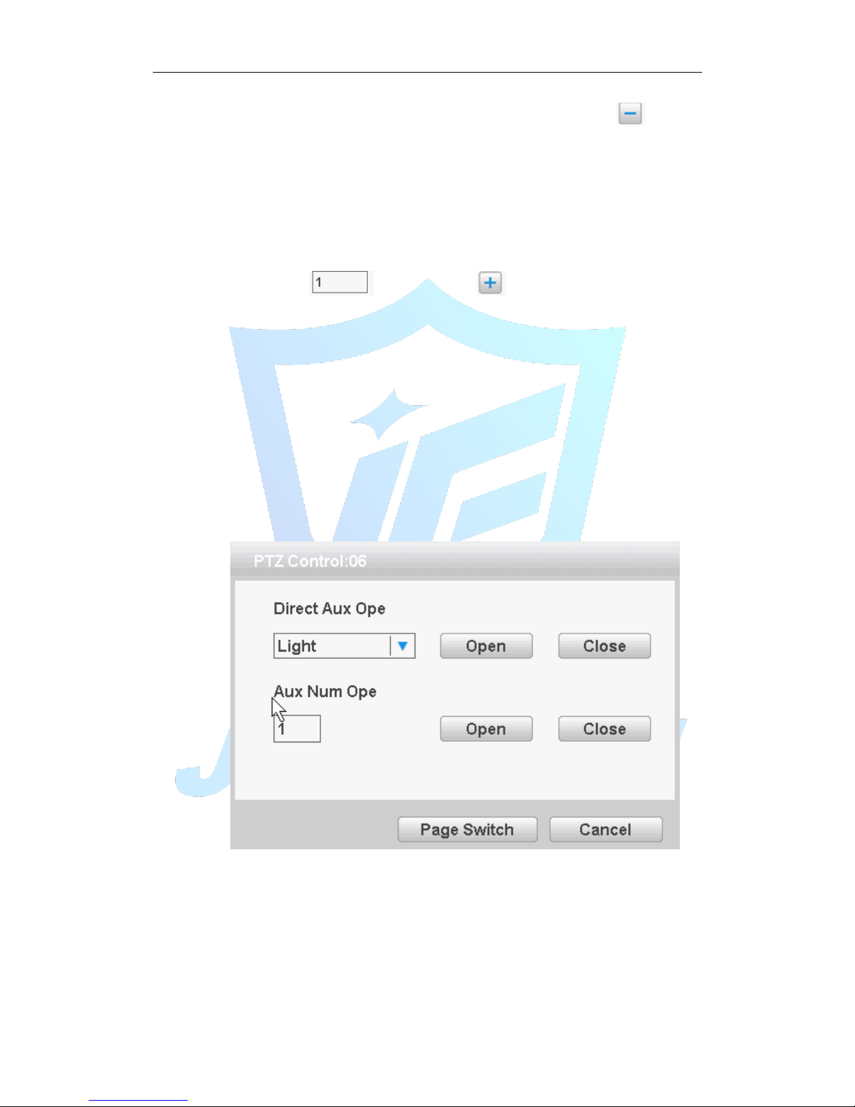
【Page Switch】
In Picture 3.12 click Page Shift button into Picture3.16, setting auxiliary function.
Figure 3.16 Auxiliary Function Control
【Intuitive Auxiliary Operation】 choose auxiliary equipment, select Open or Close
button, switch control;
【Auxiliary Number】The operation of corresponding auxiliary switch according to PTZ
agreement;
【Page Switch】In Picture 3.16,click Page Shift button enter the Picture 3.12- PTZ
Main Menu , the menu itself can be control by the menu control buttons
Page 28
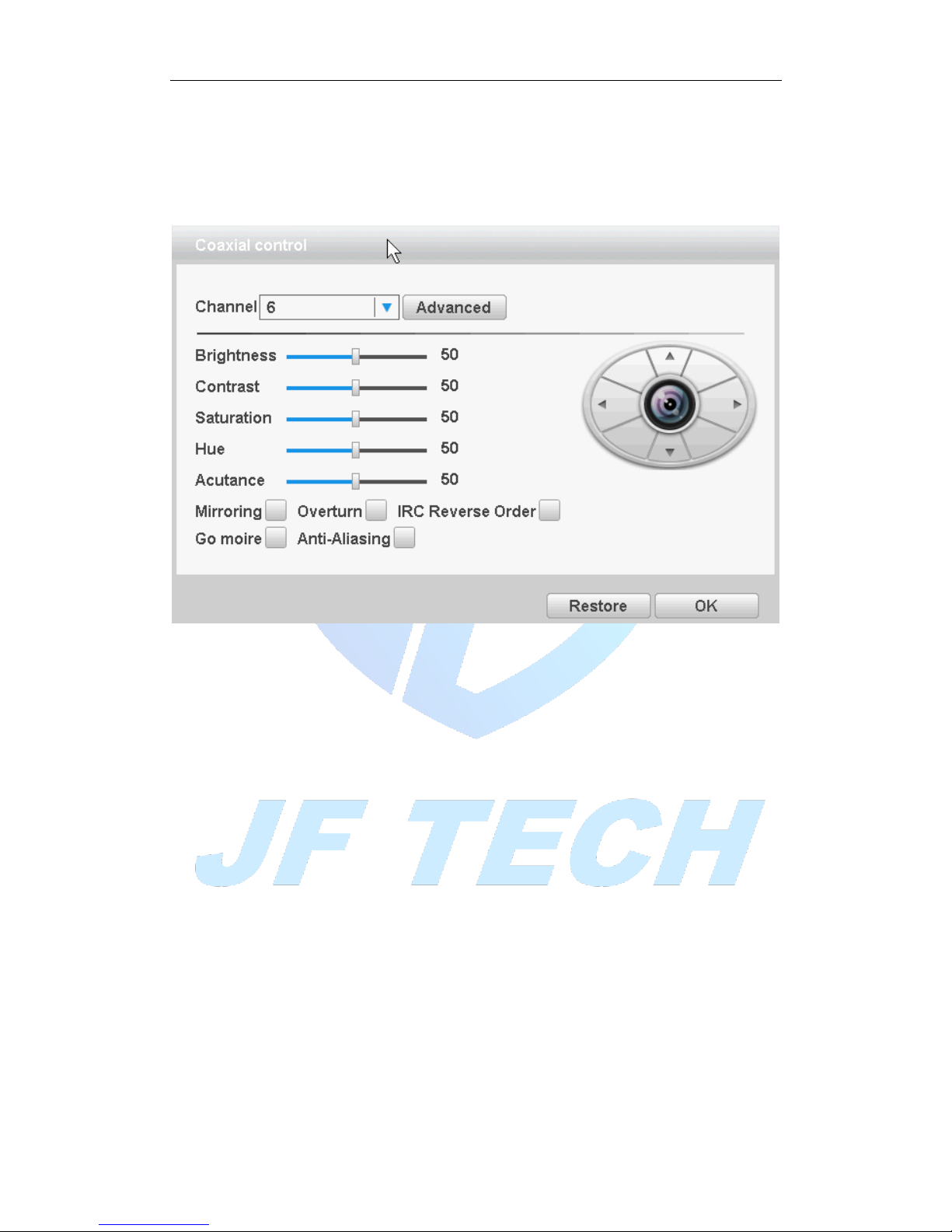
3.5.7 coaxial control
The coaxial control function enables the video recorder to transmit the control signal to the front
end camera through the coaxial cable. The DVR can control the front camera’s PTZ ,menu and
other function through the control signals. Coaxial control function requires the front camera also
supports coaxial control function
Figure 3.17 coaxial control
3.5.8 Image Color
*Image color on ONVIF device connection is invalid.
Set selected channel image parameters (when single-screen preview of the current
channel, multi-screen cursor to where the channel), you can use the desktop shortcut
menu, enter the interface. Image parameters include: brightness, contrast, saturation,
hue, gain, horizontal sharpness, vertical sharpness. And according to the needs of
different image parameters set in two different time periods.
Page 29
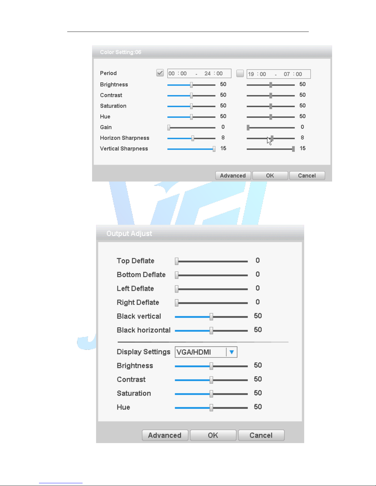
Figure 3.18 Image color
3.5.9 Output Adjust
Adjust TV output area parameters. You can use the desktop shortcut menu to choose
“Output Adjust”.
Page 30
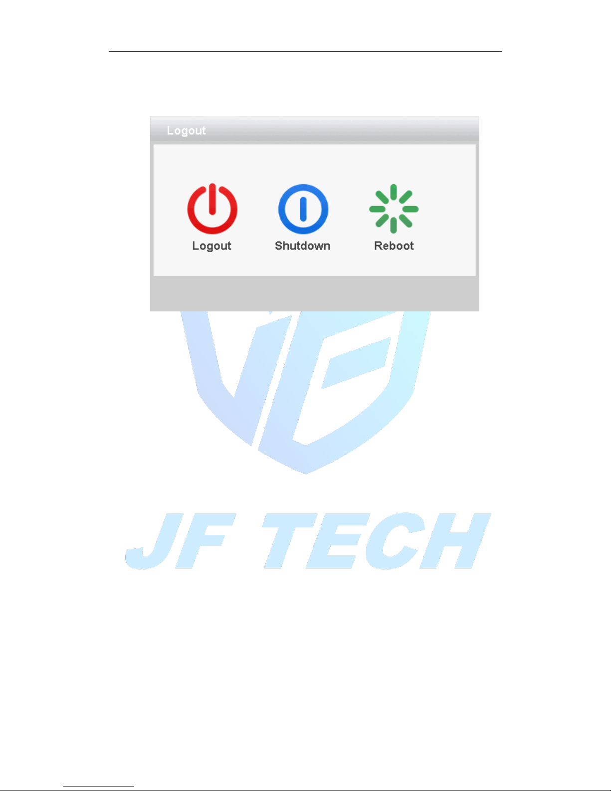
Figure 3.19 Output Adjust
3.5.10 Logout
Logout shut down the system or reboot up. You can use the desktop shortcut menu
Figure 3.20 Logout/Shutdown/Reboot the system
【logout】Quit the menu. Offer password next entrance.
【shut down】Quit the system. Turn off the power supply.
When press the shut down button, there is schedule hint. After three seconds, the
system is shut down. Cancel midway is of no effect.
【reboot】Quit the system. Reboot up the system.
3.5.11 Window switch
Preview in single window/four windows/eight windows/nine windows/sixteen
windows according to your choice.
3.5.12 SPOT
This feature is only supported by some models, a BNC connector for Spot interface, the
user can switch SPOT output split screen mode via the context menu. After receiving
the BNC interface, regardless of what to do at the end VGA, TV-side output device only
a preview screen will not display the GUI interface of the device.
It can be selected according to the needs of different screens, can be single picture,
four pictures, sixteen screen preview.
Note: The total number of different video input device, which can switch the preview
screen is different.
Page 31

4. Main menu
4.1 Main menu navigation
Main menu
Sub menu
Function
Record
function
Record Config
Recording configuration, recording type, recording time, etc.
Backup
Detect backup devices, formatting backup device, backup
selected files
Playback
Video search, video player, video file
Event
function
Motion
Detection
Set channel, device type, and set the linkage parameters: Arming
time, alarm output, screen prompts, video, PTZ, round robin,
beep, EMAIL, FTP upload
Video blind
Video loss
Alarm input
Abnormality
No hard drive, hard disk error, lack of disk space, off network
events occurred after the IP conflict time, setting the linkage
parameters: screen prompts or buzzer
Intelligent
Determination algorithm rules: perimeter guard, care items,
video diagnostics.
Set rules: show trail, sensitivity, minimum travel distance, alert
mode, and set the linkage parameters: Arming time, alarm
output, the screen prompts, recording, PTZ, round robin, beep,
EMAIL, FTP upload, phone reporting
System
settings
General
Set the system time, date format, time format, language, hard
disk full operation, the machine ID, video format, output mode,
standby time, daylight saving time
Encode
Set each channel coding and combinations coding main
parameters: encoding mode, resolution, frame rate, stream
control, quality type, code stream value, I frame interval
parameters, video / audio enabled; Note: Mixed mode and full
simulation mode only encoding settings.
Network
Set basic network parameters, and set DHCP, DNS parameters,
network speed download
Network
Services
PPPOE, NTP, Email, IP permissions, DDNS parameters
Display
Set the preview hint icon state, transparency, resolution, VGA
(HDMI) priority
Page 32

RS485
Set protocol, address, baud rate, data bits, stop bits, parity
RS232
Set the serial port function, baud rate, data bits, stop bits, parity
Tour
Set touring mode and interval
Advanced
Storage
Set the specified hard disk drive to read and write, to read-only
disc, set to redundant disk, clear the data, data recovery and
other operations
Account
Modify users, modify group, change passwords, add users,
increasing the group, delete users, delete groups
Online user
May have been forcibly logged off the network users, after
disconnecting the account will freeze to recover when the next
boot
Import/Export
Import or export the DVR’s conifguration
Upgrade
Upgrading using external devices (such as USB)
Auto
Maintenance
Set automatic reboot the system automatically delete the file
time
Restore
Restore settings Status: Normal settings, video settings, alarm
settings, network settings, network services, output mode, the
serial port settings, user management
Device
information
Configure some device hardware information
Import/ export
Exporting logs or configure the device to an external device (such
as U disk); connect an external device (such as U disk)
configuration import equipment
Digital
Set channel mode, view the channel status, and set the
parameters of digital channels, etc.
Info
HDD Info
Display hard disk capacity, recording time
BPS
Display stream information
Log
Query log, and clear all log information
Version
Display version information
4.2 Record function
Video-related operations, including: record settings, video playback, video backup.
4.2.1 record settings
Set video parameters monitored channel. When you first start, the system is set to 24
Page 33
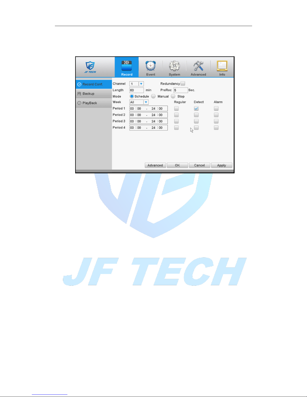
hours of continuous recording. [Main menu]> [record]> [record config].
Note: The normal recording equipment, installation of a hard disk with at least one set
to read-write disk (detailed operation, please refer to section 4.5.1)
Figure 4.1 video settings
[Channel] to select the appropriate channel number for the channel set, selectable
settings for all channels unified whole;
[Redundancy] choose redundancy capabilities that enable video file double backup
function, a forthcoming video channels simultaneously recorded onto two hard drives.
There are two devices need to install the hard drive, where a hard disk read-write disk,
a redundant disk (detailed operation, please refer to section 4.5.1);
[Length] to set the length of time for each video file, the default is 60 minutes;
[Mode] setting the video, there are three states: configuration, manual on and off;
Configuration: video recording in accordance with (general, detection and alarm)
recording type and recording time period set;
Manual: No matter what state the current channel, select "Manual" button, the
corresponding channel all for normal video;
Off: No matter what state the current channel, select the "off" button, the
corresponding channel to stop recording.
[week] setting common recording time period within the time set will start recording;
[Type] set record type, there are three types: normal, detection and alarm.
Regular: In the time period set for normal video, video file type is "R";
Detection: In the time period set trigger "motion detection", "video block", "video
loss", "Exception Handling" alarm signal, and the corresponding alarm function is
set to open the Video function, start detection recording, video files type "M".
Alarm: In the time period set trigger external alarm signal, and the "Alarm Input"
function is set to open the video function, start detection recording, video file
type is "A".
4.2.2 playback
Page 34
View chapter "3.5.3 video playback."
4.2.3 video backup
By setting the backup device video file to an external storage device.
Note: Before backup files, you need to install the files stored to accommodate storage
devices. Backup is terminated; it has been copied to a storage device files can be played
back independently.
Backup middle is terminated, has been copied to a storage device files can be played
back independently.
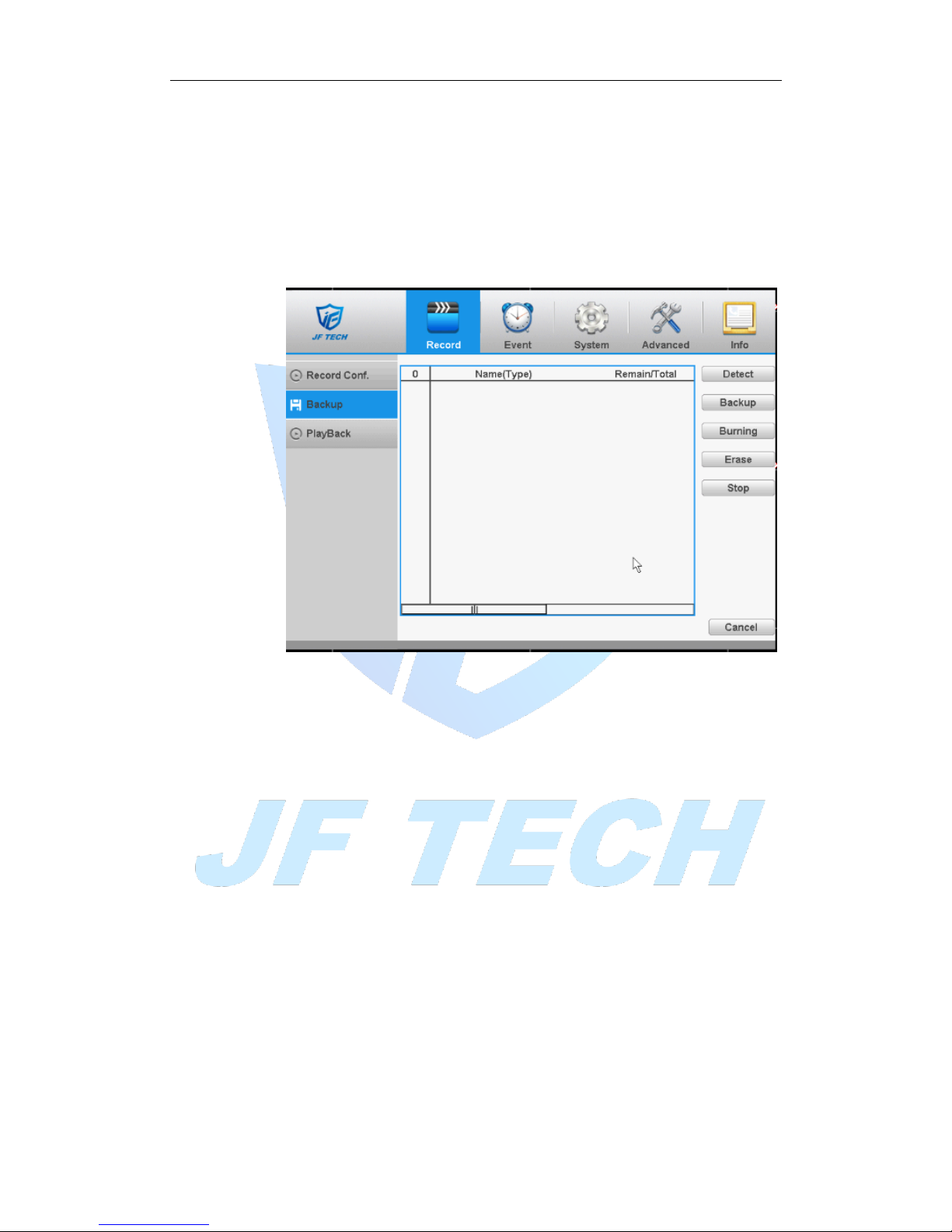
Figure 4.2 record backup
Detect: Detecting storage devices connected to the device, which can be U disk, hard
disk and other equipment;
Backup: Click Backup, Backup dialog box pops up, you can select the backup video files
based on type, channel, time and other attributes.
When you click “backup”, then you’ll enter next page:
Clear: Clear the displayed file information;
Added: Display file information to meet the set file attributes;
Backup Format: The format of the configuration backup file, according to the needs,
the optional H264 or AVI.
Start / Stop: After select the file and backup format, click to start the backup, and then
click Stop to stop the backup.
Note: When you back up, you can exit the page perform other functions.
Burning: Click Burn, burn video will sync selected channel;
Erase: Select the file to delete and click erasure to delete the device files;
Stop: Stop the backup;
4.3 Event function
Alarm functions include: motion detection, video blind alarm, and video loss alarm,
Page 35
alarm input alarm, intelligent analysis and abnormality.
4.3.1 motion detection
By analyzing the video image, when the system detects a mobile signal, motion
detection alarm is initiated, and the linkage functions.
Note: The front-end equipment and this equipment need to enable this feature.
Advanced button same to the right mouse button.
Motion detection function of mixed mode / full analog and digital channels are
different: motion detection alarm digital channels only to turn its function at the local
end, the corresponding remote device connected to the end of the channel will have
motion detection feature is turned on, when the remote device side corresponding
channel has motion detection scene occurs, the local side will be able to achieve its
alarm function, otherwise the motion detection function cannot be achieved, while the
analog channels open as long as the local end manufacturing mobile phenomenon on
the line .
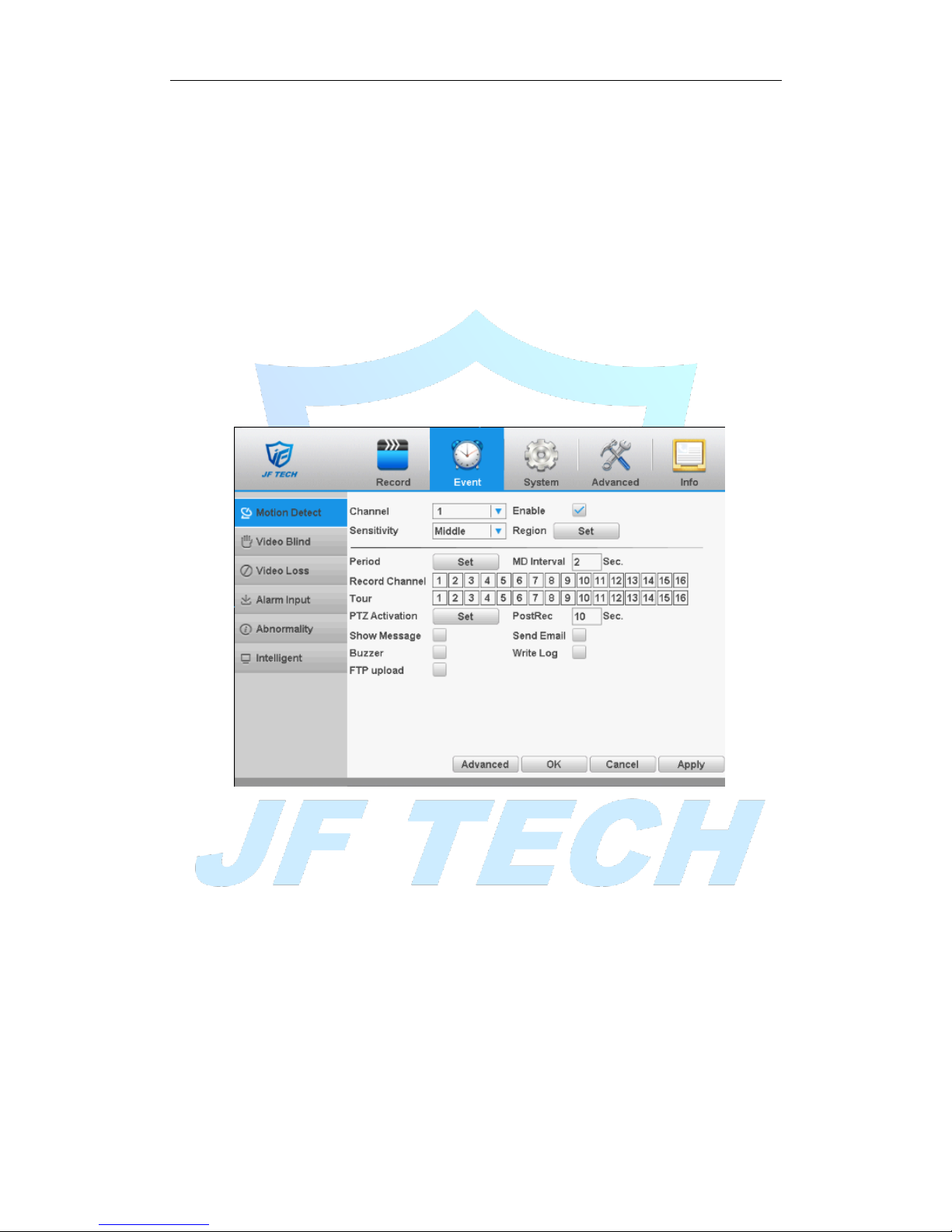
Figure 4.3motion detection
[Channel]: Select the number of channels to be set, the default one channel to the
network camera.
[Enable]: motion detection alarm enable.
[Sensitivity] according to the sensitivity level of the lowest, low, medium, high, very
high, the highest six-speed optional;
Note: where only in motion detection settings and only analog channels can set its
sensitivity of mixed mode / full analog mode.
[Region] Click Settings, enter the settings area is divided into PAL22X18, red area for
motion detection fortified area; the white area is undefended, as shown in Figure 4.5
Settings area. Hold down the left mouse button, draw settings area. (By default the
entire area selected for monitoring area) Note: Mixed mode / full motion detection in
analog mode only regional settings, and only analog channels to set their area.
Page 36
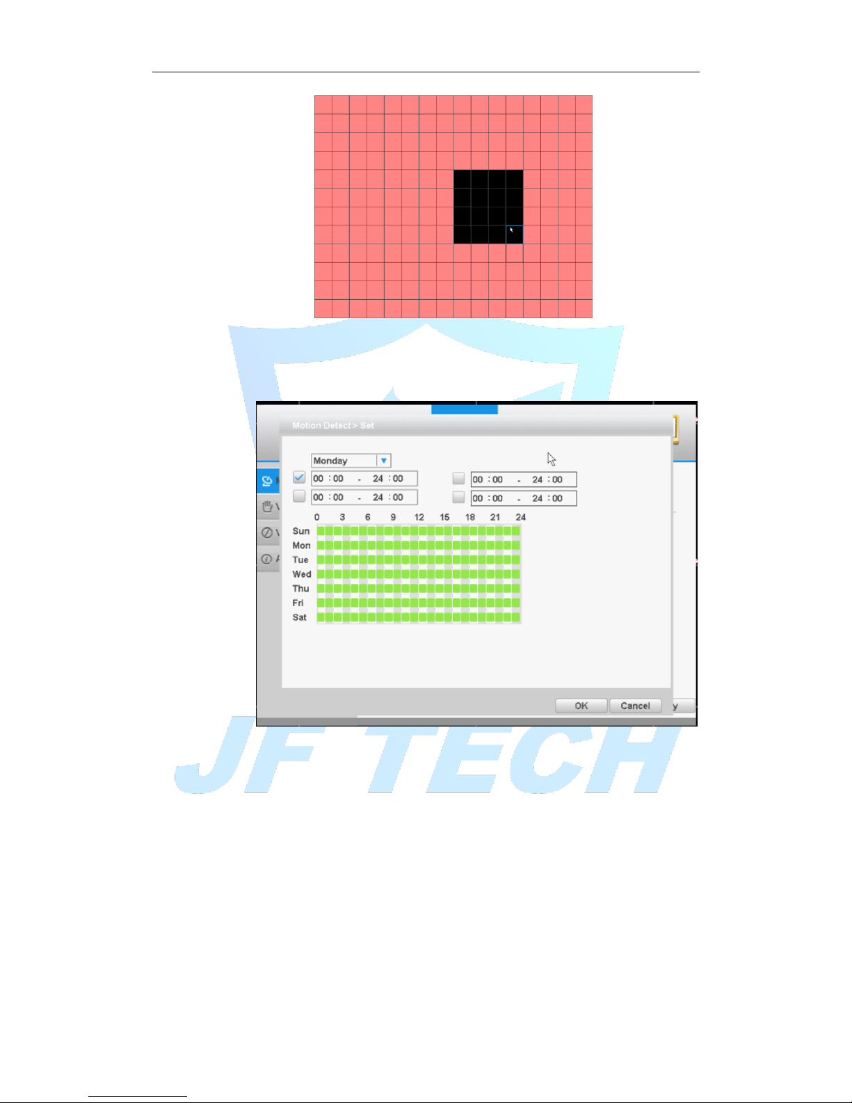
Figure 4.4 area settings
[Period]: You can also set the alarm time from Monday to Sunday every day 4 time
periods, other time will not trigger motion detection alarm information. As shown in
FIG.
Figure 4.5 time period
[MD Interval]: between two alarms generate alarm information shortest time interval
can be set between 0 and 600S.
[Record channel]: When an alarm is triggered, the DVR starts recording, you need to
open detection recording.
[Tour]: The DVR does not support this feature.
[PTZ Activation]: When alarming, it will turn off the PTZ preset point linkage or linkage
between points or cruising.
* Under Mixed mode, PTZ is linkage to analog channel corresponding PTZ settings,
under full digital channels; PTZ is linkage to PTZ information corresponding to the
remote device settings.
Note: PTZ Activation, you need [shortcut menu]> [PTZ], set the preset point, cruise
between points, intervals and other parameters
Page 37
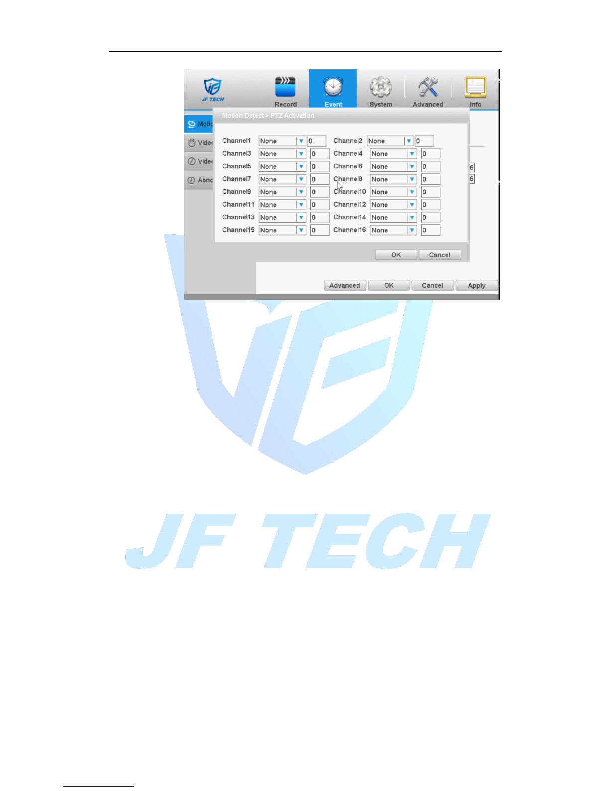
Figure 4.6PTZ Linkage
[MD interval]: After the alarm ends, the length of time to continue the local recording
can be set between 10 and 300S.
[Show message] on the local host screen, pop-up dialog box prompts warning
information;
[Send Email]: When an alarm is triggered, sends an alarm message to the specified
mailbox, mailbox settings.
[FTP Upload] ■means enable, Expressed alarm occurs if the selected channel or video
capture channel, the video file or image upload up to a specified location.
Note: Upload FTP, need to be set accordingly in the [Network Services].
[Buzzer]: when an alarm occurs, the device sends a "tick" sound long ring.
[Write Log]; when an alarm occurs, the device write a log which you can check on the
[Info]>[Log].
4.3.2 Video blind
When the device captured video images by outside influence, low light, to set the
sensitivity parameter, start the video occlusion alarm, and the linkage function.
Note: Advanced button is same to the right click button.
* Same with motion detection, the Mixed-mode / full analog and digital channels of
video blind function differently.
Page 38
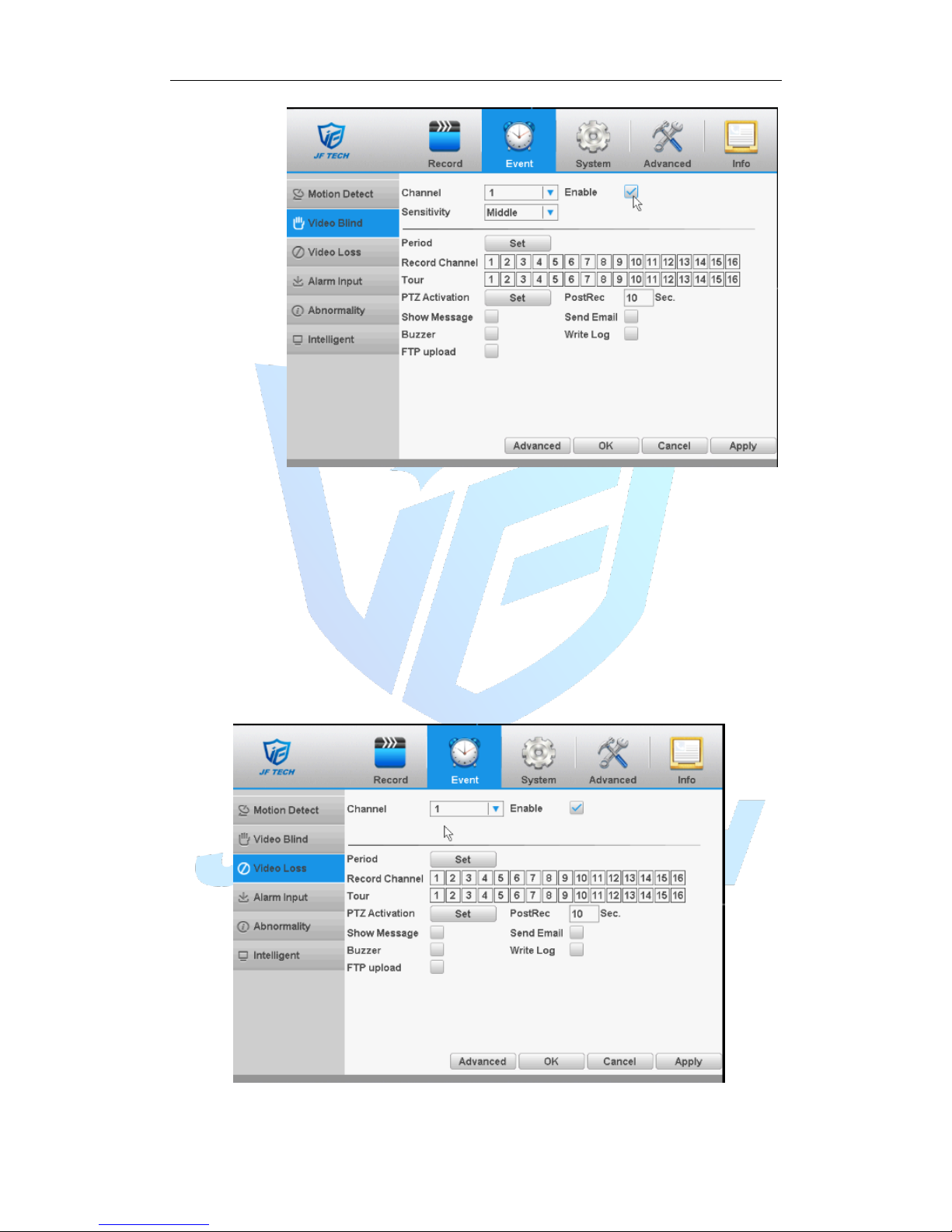
Figure 4.7 video blind
Digital channels cannot be used to set the sensitivity. Which is a mixed-mode or full
simulation mode can set the sensitivity. Sensitivity level is divided into six kinds, namely:
minimum, low, medium, high, very high, the highest.
Setting method: refer to chapter "4.3.1."
4.3.3 video loss
When the device cannot get channel video signal, the video loss alarm, and the linkage
function.
Note: Advanced button is same to the right click.
* Same with motion detection, the Mixed-mode / full analog and digital channels of
video loss function differently.
Page 39
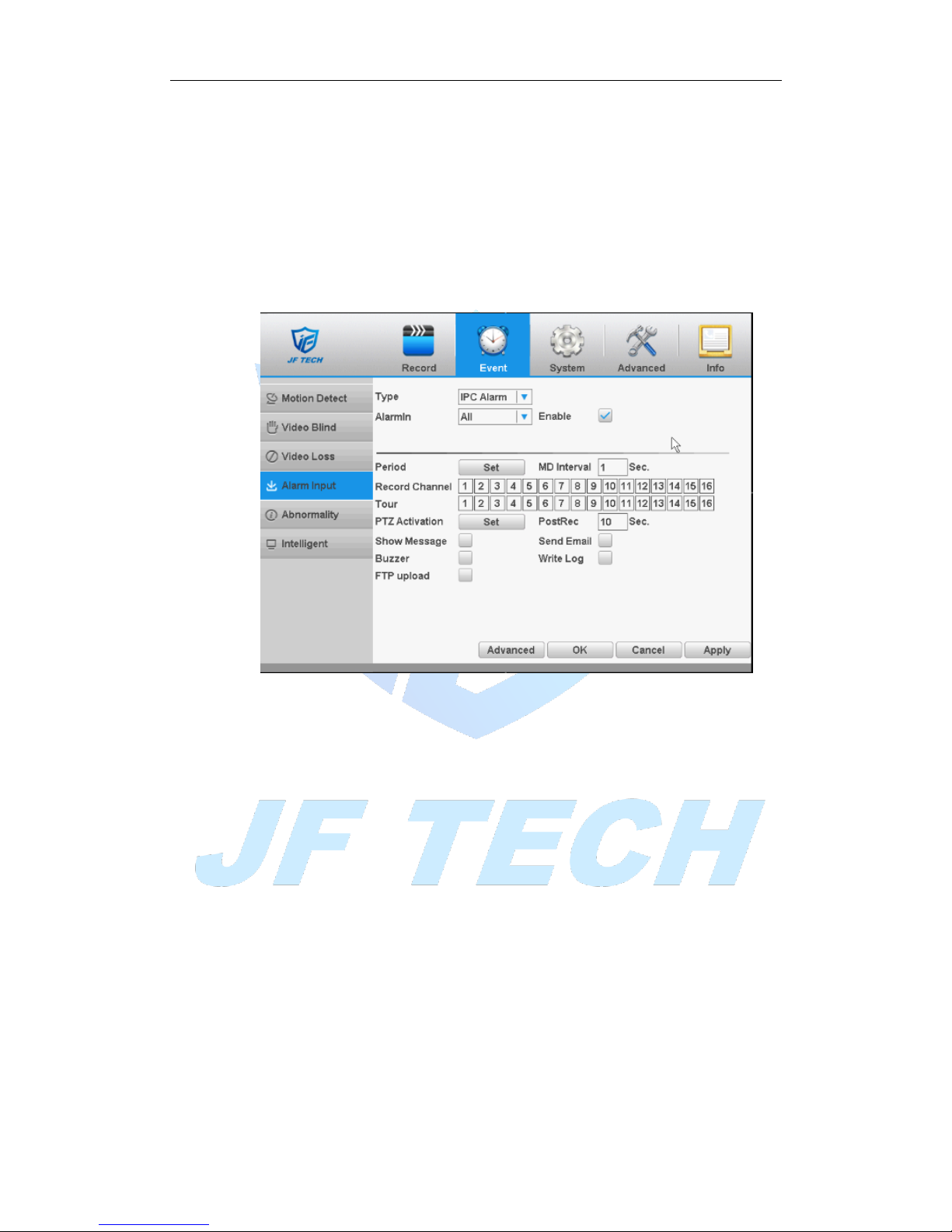
Figure 4.8 video blind
Video loss alarm configuration, please refer to 4.3.1 motion detection section.
4.3.4 Alarm input
When the device gets an external alarm device alarm signal, it will start alarm function.
* Alarm input, mixed-mode / full analog channel mode and use the same digital
channel mode, the function is turned on, if set to normally open, you only need to plug
the alarm terminal on the local end of the alarm inputs, alarm information will be
generated , but also the corresponding linkage setting function.
Note: Advanced button is same to the right click.
Figure 4.9 Alarm input
Setting method: refer to chapter "4.3.1."
4.3.5 Abnormality
Some current hardware and software analysis and detection equipment, and when
there is an abnormal event is detected, the device responds accordingly, for example,
the screen tips, buzzer, etc.
Page 40
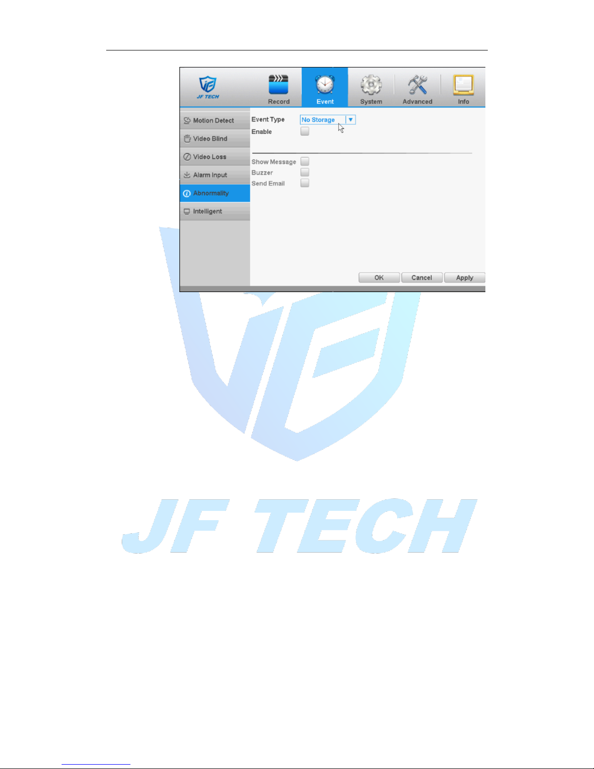
Figure 4.10exception handling
[Event Type] in the drop-down box to select the detection of abnormal
[Enable] ■ Means open the exception handling feature.
[Show Message] screen on the local host screen, pop-up warning message prompt
dialog box;
[Buzzer] when an alarm occurs, the device sends a "tick" sound long ring.
[Send Email]: When an alarm is triggered, sends an alarm message to the specified
mailbox, mailbox settings.
4.4 System settings
Including General, encoding, network, network services, Display, PTZ Config, Tour.
4.4.1 General settings
Page 41
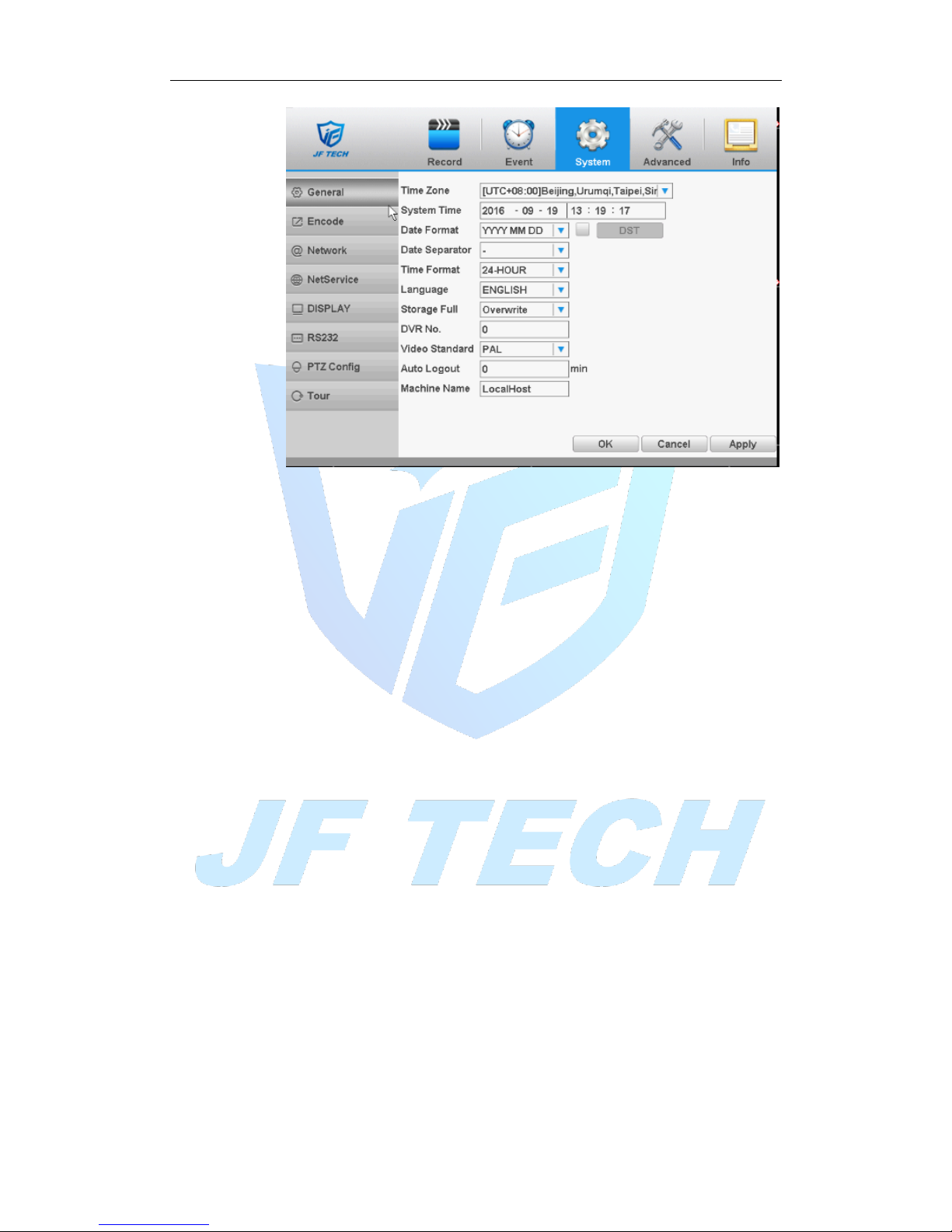
Figure 4.12 general settings
[Time Zone]: The default is CMT +8
[System time]: set the system time manually.
[Date Format]: provide Year Month Day/ Month Day Year/ Day Month Year three
formats.
[Date separator]: Set the preview screen displays the date when the delimited format,
provide a "-""." "/" three formats.
[Time Formate]: Select the time format of 12 or 24-hour two kinds, default is 24.
[Language]: Set the system language, Simplified Chinese, Traditional Chinese, English
and other 20 languages.
[Storage Full]: the hard disk is full, the measures taken by the camera.
Overwrite: TF card file overwrites the oldest video or capture full time to continue
recording and capture.
Stop: TF card when you stop recording and capture video or capture full.
[Video Standard]: Select the video format supports both PAL and NTSC formats.
[DVR No.] for this machine with a remote control remote control multiple DVR
occasions, only address key is pressed on the remote control and enter the remote
locations and the local number corresponding DVR remote control to operate the same
address.
[Auto Logout] can be set menu is not set standby time 0-60, 0 standby time;
[Machine Name] can be set to the name of the device.
Page 42
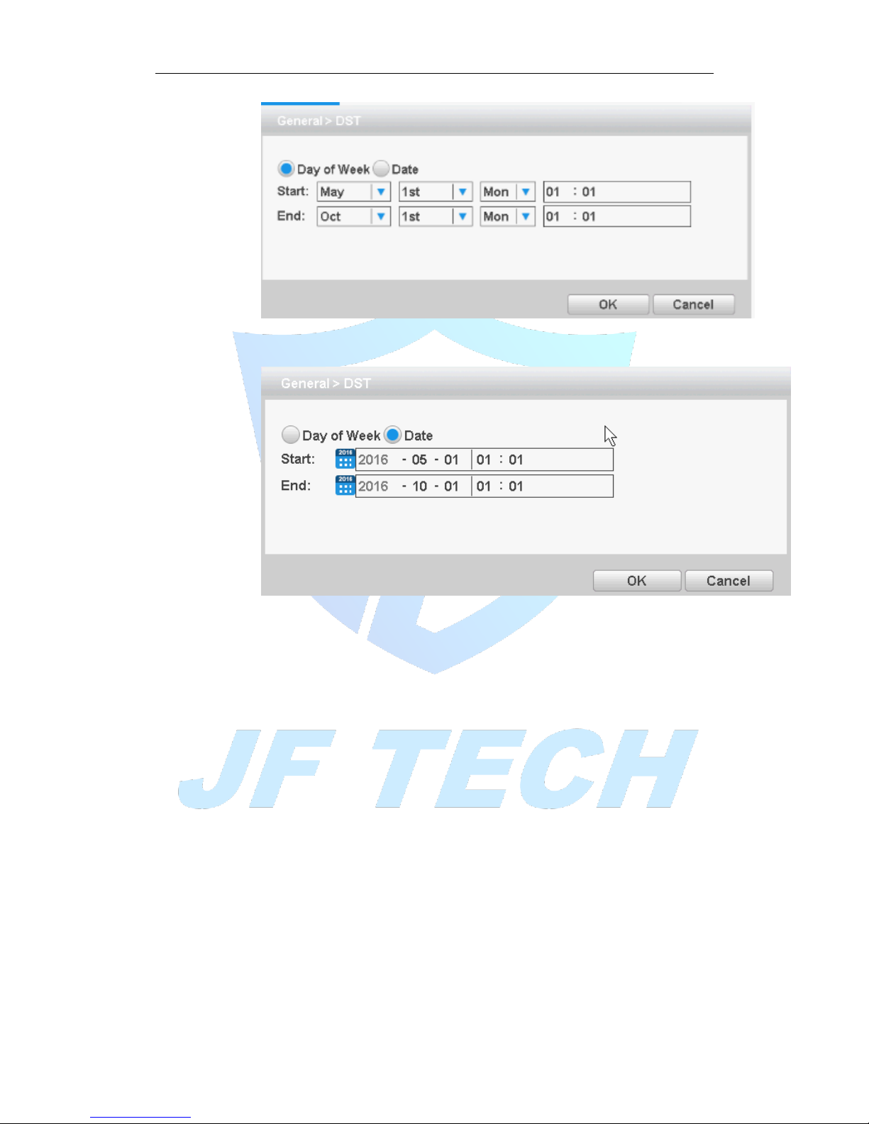
Figure 4.13 Daylight Saving Time (weeks) setting
Figure 4.14Daylight Saving Time (days) setting.
4.4.2 Encoding settings
* When the product is set to mixed mode / full analog channel mode, the system will
be set up in the encoding setting function, encoding settings can only function in an
analog channel encoding settings.
Set the video / audio encoding parameters including video files, remote monitoring and
other image parameters. The left part of each individual channel set encoding
parameters, the parameters set on the right part of the secondary stream, dual-stream
uses 1080P / 720P / 960H / D1 / HD1 / CIF / QCIF encoding rate of the stream all the
way to high definition for local storage, support all the way to low bit rate stream (QCIF
coding) for network transmission, taking into account local storage and remote network
transmission. Dual-stream network bottlenecks in the existing balance between image
quality and transmission quality, can break through the bottleneck of the network, the
flexibility to select the format according to the network bandwidth stream, to local HD
storage, while the rear end of the transmission of low stream networks.
Note: The main application of the secondary stream is for multi-channel real-time
monitoring, mobile monitoring under poor network.
Page 43
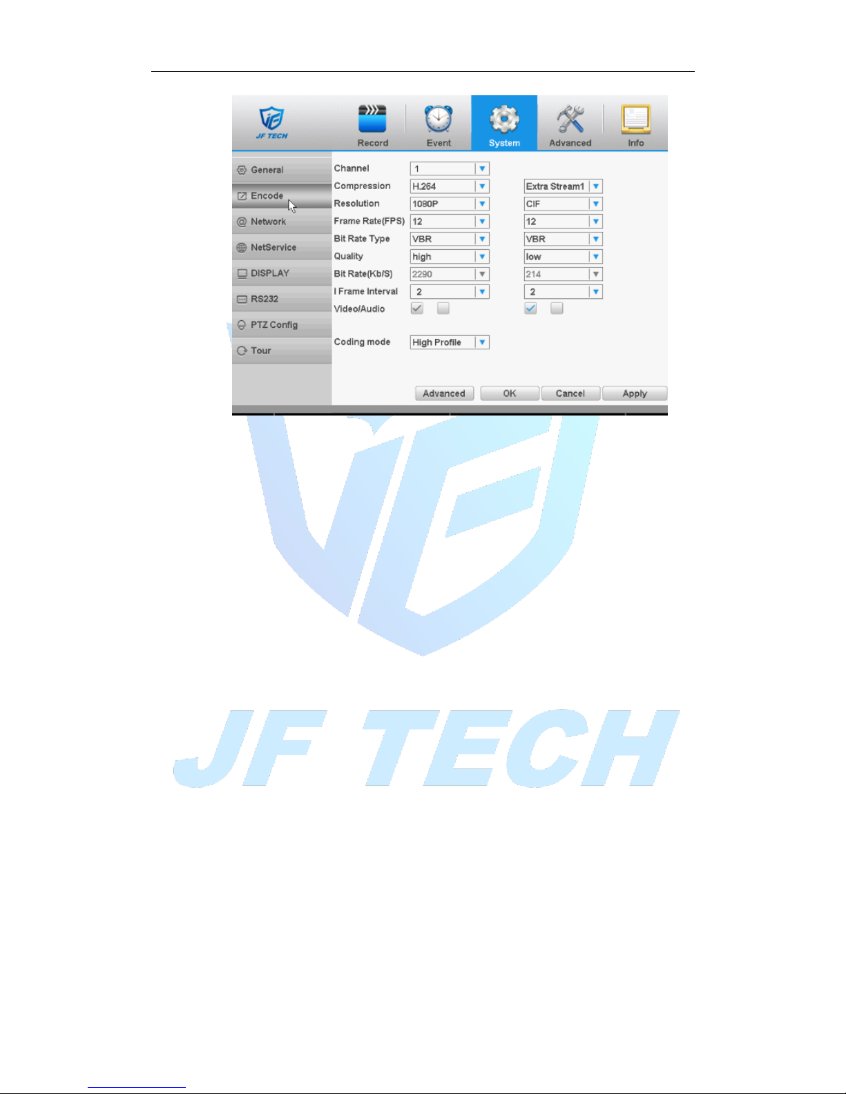
Figure 4.15 encoding settings
[Channel] to select the channel number; display the corresponding channel
information;
[Compression] coding standard H.264MP
[Resolution] as obtained from the front-end device connected to the encoded
information;
[Frame Rate] can be adjusted, according to the acquisition front-end coding prevail,
DVR, and front-end equipment will take effect after adjustment;
[Bit Rate Type] including Limited stream and variable stream;
[Quality] set the stream value to change the quality. In facilities allow, the bigger stream,
the better the quality;
[Bit Rate] According to the code stream flow control and quality varied selection
[I frame Interval] selectable frame interval range 2-12s
[Video / Audio] icon when all of the highlighted video file to audio and video composite
stream; auxiliary stream setting auxiliary stream mainly used for client monitoring, cell
phone monitoring.
The resolution, frame rate, stream control, stream parameters is same with the
independent channel parameter settings.
4.4.3 Network
Configure IP address, gateway, DDNS of DVR.
Page 44
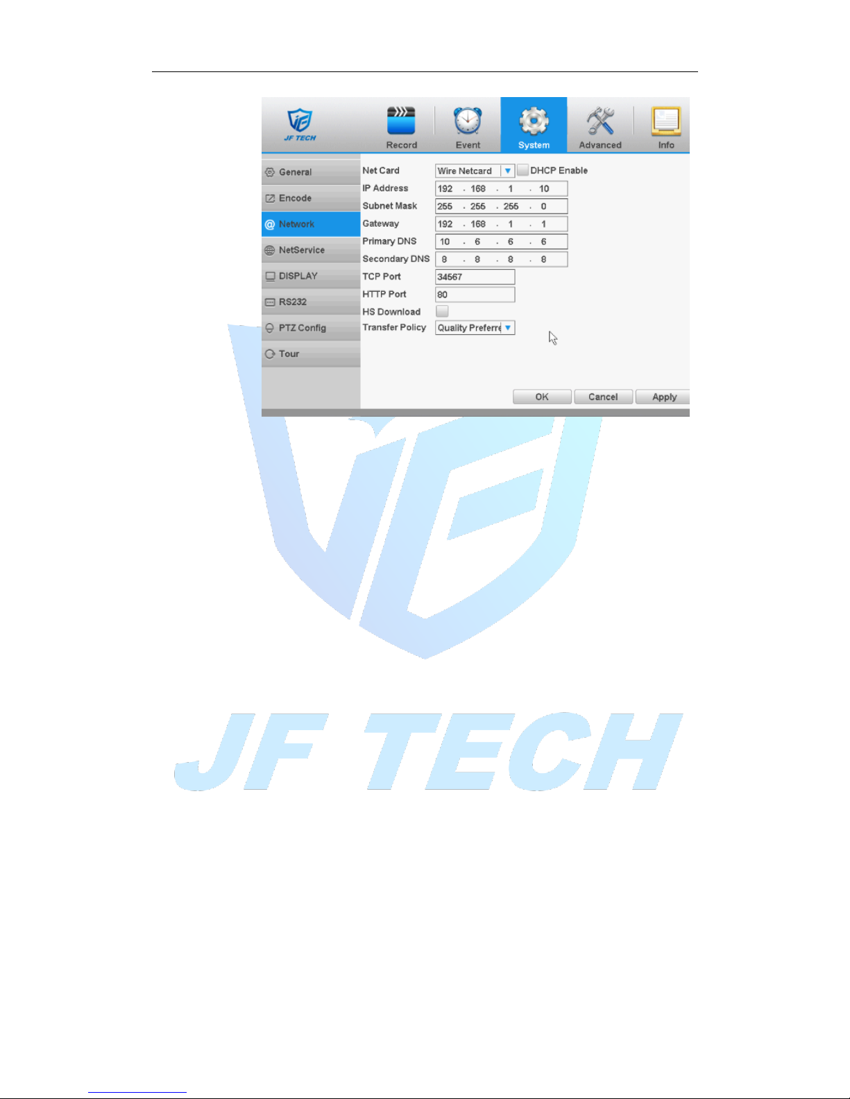
Figure 4.16 network settings
[DHCP Enable]: The DVR is connected to the router which DHCP is open; then DVR will
automatically obtain an IP address.
[IP Address]: The IP address of the DVR is used to login network, the default is:
192.168.1.10.
[Subnet Mask]: Set the DVR's subnet mask, to be consistent with the login computer,
default is 255.255.255.0.
[Gateway]: Set the default gateway of the DVR to be consistent with the login computer,
the default is 192.168.1.10.
[Primary DNS]: Set the DVR's DNS , to be consistent with the login computer, DNS
incorrectly can cause XM Cloud function does not work properly.
[TCP port]: Set the DVR's TCP port, the default port is: 34567.
[HTTP port]: Set the DVR's HTTP port, the default port is: 80.
[HS download] Network speed downloads.
[Transfer Policy]: Set the network transmission strategies, adaptive / quality priority /
smooth priority / network transmission priority four kinds of policy options.
Adaptive: when network bandwidth is small, the preview screen automatically jump to
sub-stream, to ensure smooth preview.
Quality Priority: Whether the network bandwidth is large enough, the preview screen is
always displayed in the main stream, when the bandwidth is not enough screen will
delay.
Smooth priority: Under no circumstances reduce the frame rate, encoder settings
change, reducing the size of the stream, to ensure smooth screen.
4.4.4 Network Services
Configure PPPoE and other functions of the DVR.
Page 45
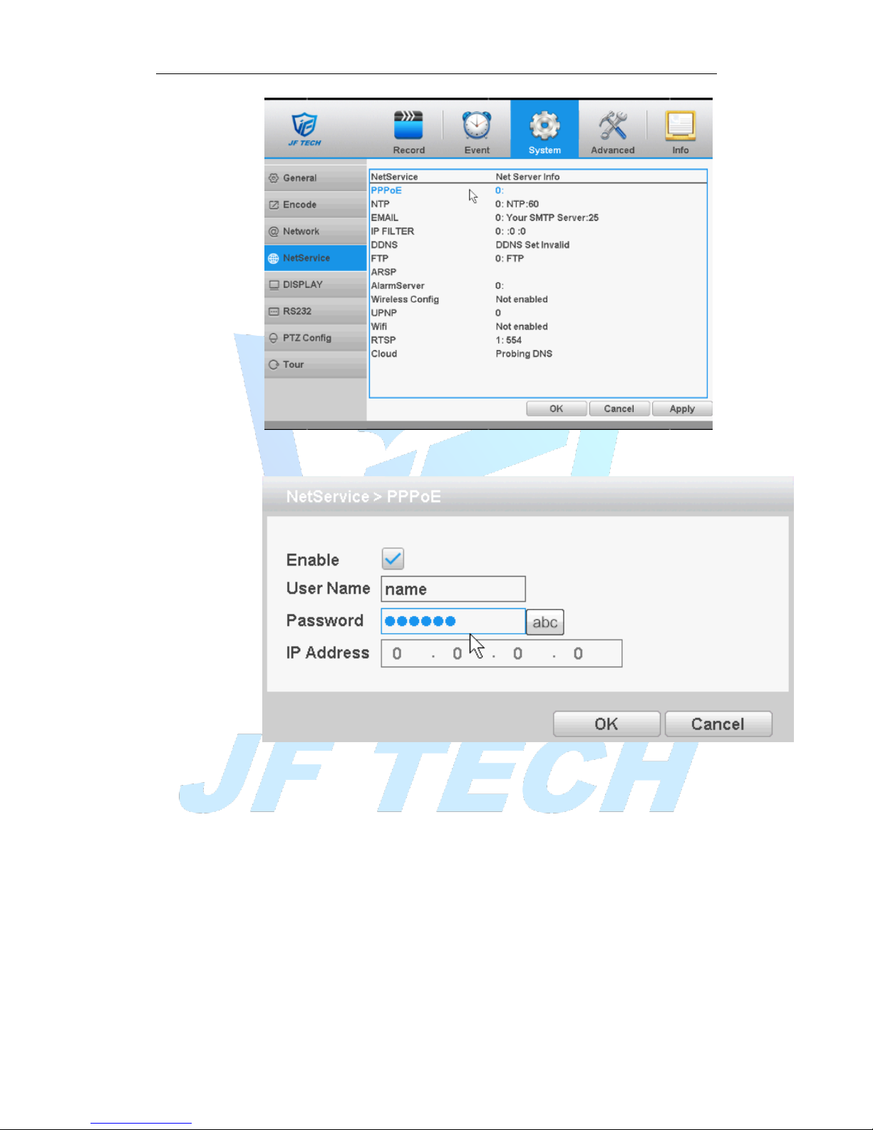
Figure 4.17 network services
[PPPoE settings]:
Figure 4.18 PPPoE
Enable: Anti ■ means enabled.
Enter the ISP (Internet Service Provider) to provide the PPPoE username and
password, restart the system after saving. After starting the DVR will automatically
establish a network connection to the PPPoE mode, after the success, IP [IP
address] will be automatically modify the dynamic WAN IP address obtained.
Operation: After PPPoE dialing successfully, view IP [IP address] on, get the current
IP address, and then uses this IP address to access the device via the client.
[NTP]:
Page 46
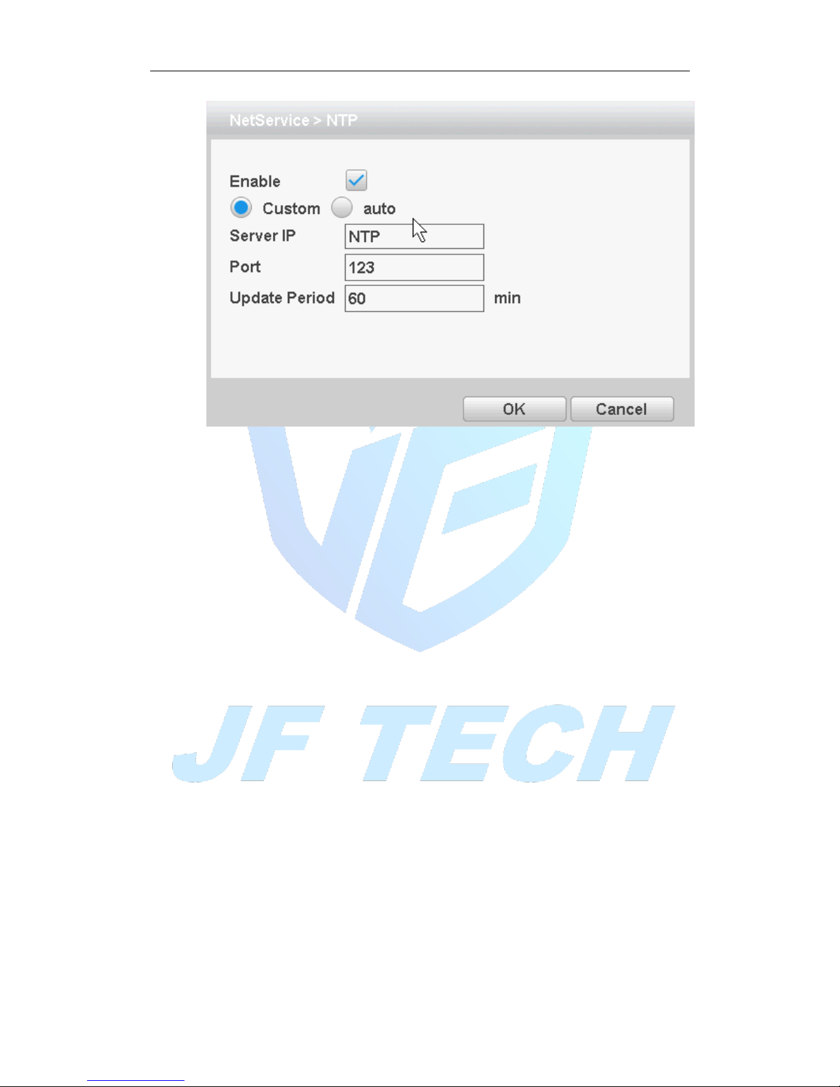
Figure 4.19NTP settings
It required install the NTP service on the PC.
Enable: Anti ■ means, select Enable, set to take effect.
Server IP: Enter installed NTP server PC IP;
Port: The default NTP port 123, the port settings can be based on actual NTP server;
Update Period: the same NTP server check interval, the default is 10 minutes.
[Email]:
Set the e-mail addresses for DVR sent and received alarm information.
Page 47
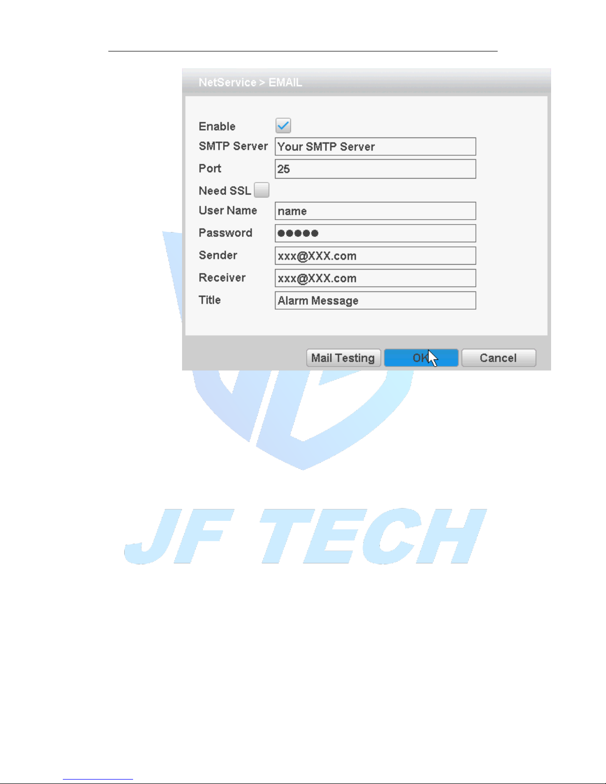
Figure 4.20 Email settings
[SMTP server]: Log mailbox to query entry method SMTP server in mailbox
settings.
[Port]: The mail server port number;
[Need SSL]: consistent with the mailbox configuration, you can log in to view the
mailbox into the mailbox settings.
[User Name]: Only fill in email address before the @.
[Password]: Password for the user name of the application.
[Sender]: Set the message sender EMAIL address.
[Receiver]: You can set up to three e-mail address, separated by a semicolon, can
outbox the same e-mail address.
[Title]: subject of the message, you can set your own.
[IP Filter]
When choosing the white list, the list represents only the IP to connect this DVR. A list
of supported 64 IP settings;
When selecting the blacklist, represents a list of the IP network cannot be landed this
DVR. A list of supported 64 IP settings;
You can tick check, delete the set IP.
Note: When the black and white list, have the same IP address blacklist authority
higher priority.
Page 48
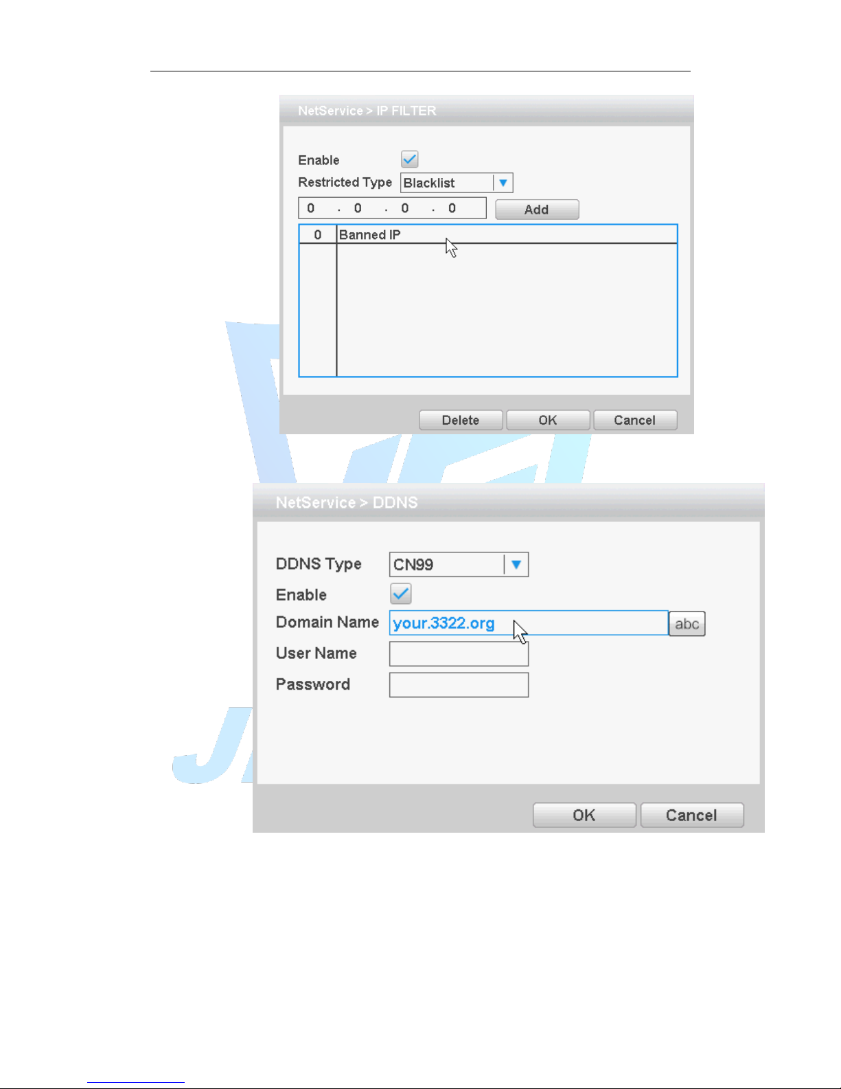
Figure 4.21IP rights settings
[DDNS]
Figure 4.22 DDNS settings
It is the abbreviation of dynamic domain name server.
[Domain name]:Provide the domain name registered by DDNS.
[User name]:Provide the account registered by DDNS.
[Password]:Provide the password registered by DDNS.
When the DDNS is successfully configured and start, you can connect the domain name
in the IE address column to visit.
Page 49
Note:The DNS setup must be configured correctly in the network setup.
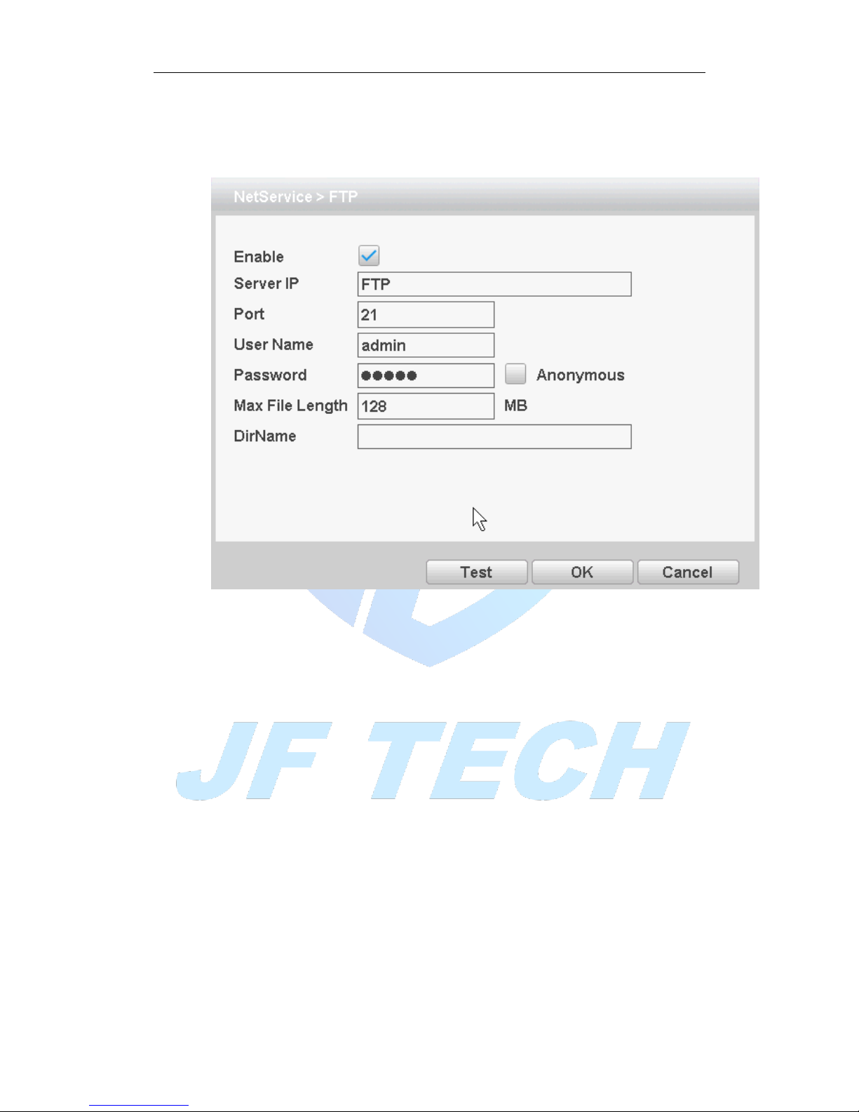
[FTP settings]
FTP is used when there is an alarm generated, or the alarm linkage video, capture
pictures, you can upload to a specified FTP server specific video and capture pictures.
Figure 4.23FTP settings
[Enable]: Anti ■ means, select Enable, set to take effect;
[Server IP]: IP address of the FTP server;
[Port]: FTP port number field when built, the default port 21;
[User name]: have permission to log onto the FTP user name;
[Password]: The user's password;
[Anonymous]: Anti ■ means, chose to be anonymous, you do not need to set the
user name and password;
[Max File Length]: Each package upload files maximum length, default is 128M;
[DirName]: file directory to upload files.
Note: The username is entitled to upload files to the server.
[ARSP]
By setting, you can start DDNS Sever add the device to the DDNS server for device
management
Page 50
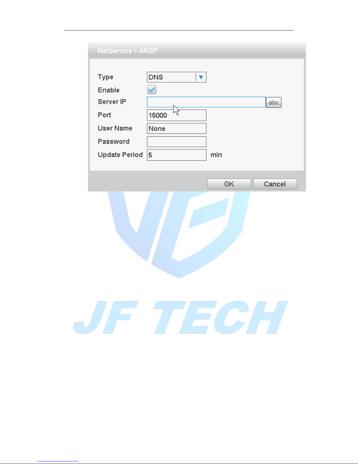
Figure 4.24ARSP
[Type]: Select the DNS
[Enable]: Anti ■ means, select Enable, set to take effect;
[Server Ip]: IP address of the DDNS server;
[Port]: Device port number corresponding DDNS server "service listening port";
[User Name]: The user name of the device login DDNS server;
[Password]: The password corresponding to the user name;
[Update Period]: Equipment and DDNS synchronization interval
Note: before using the need to build DDNS Server
[Alarm Server]
After an alarm, it report alarm information to alarm server.
Page 51
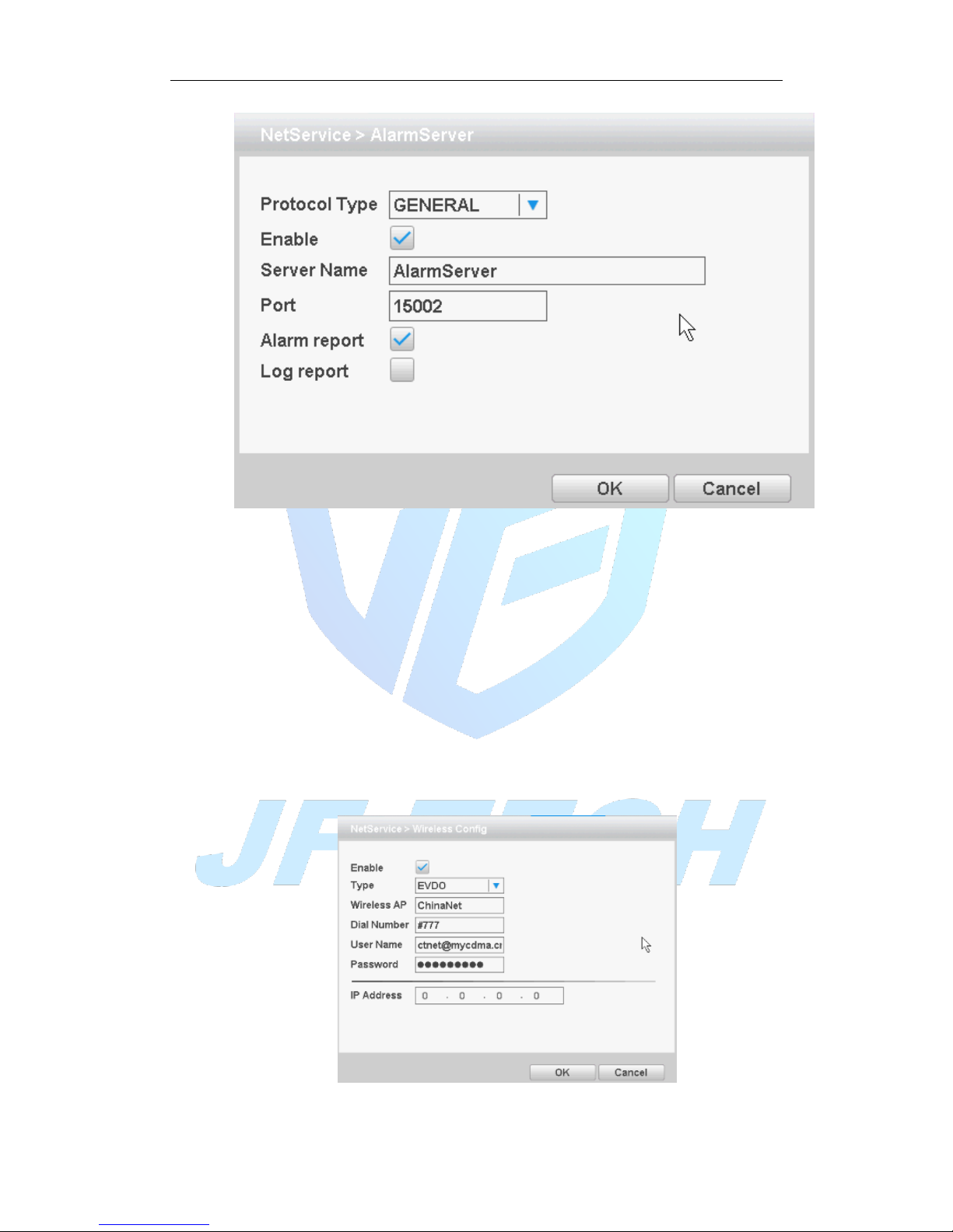
Figure 4.25 alarm center
[Protocol type] GENERAL;
[Enable] ■ means selected, select Enable, set to take effect;
[Server Name] IP address of alarm server;
[Port] port number of the device;
[Alarm report] reported anti ■ means, reported to the police information to the
server;
[Log report] Anti ■ means, reported to the server log information.
[3G settings]
Dial-up Internet access through 3G card, implement client access device, configure the
device
Figure 4.26 3G settings
Page 52
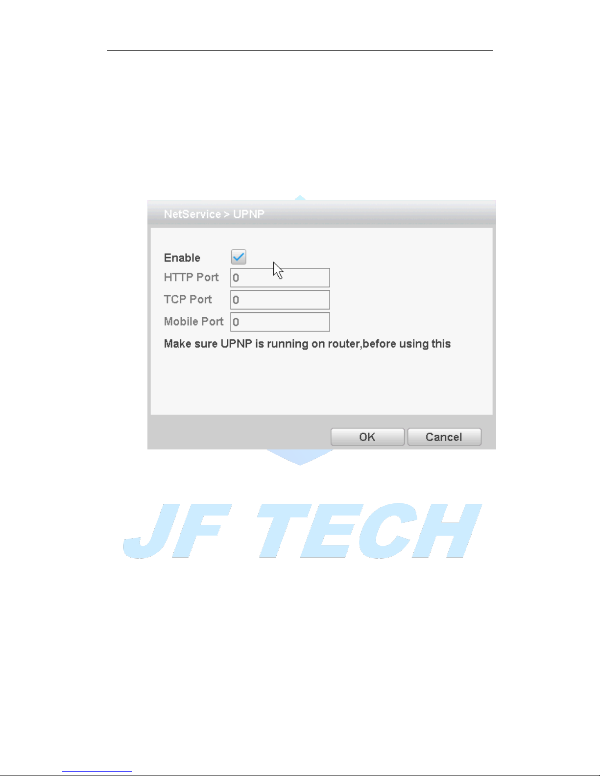
[Enable]: Anti ■ means, select Enable, set to take effect;
[Type]: Dial type, default automatic
[Wireless AP]: 3G access point, the default can
[Dial number]: 3G dial number, the default can
[User name]: Dial 3G username
[Password]: dial the user's password
[IP address]: The IP address of the dial-up number to get
[UPNP]
UPNP protocol can forward automatically on the router.
Figure 4.27 UPNP settings
[Enable] ■ means, open the UPNP feature, select the Enable, set to take effect;
[HTTP Port]: router for the device is automatically assigned port numbers, IE browser,
the need to add the port number to access;
[TCP Port]: When the router is automatically assigned port for the device, client
software monitoring required by the port number;
[Mobile port]: router for the device is automatically assigned port numbers, mobile
phone monitoring needs through the port number;
[WIFI]
Connect to the wireless router via the wireless module. To access the device via IP,
provided the use of this feature is that the DVR has access to WIFI module.
Page 53
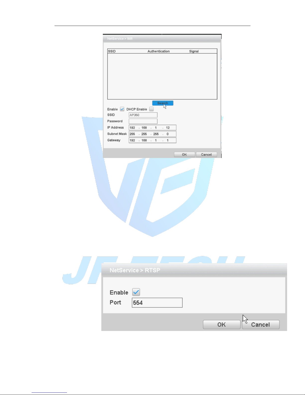
Figure 4.28 WIFI settings
[Search]: Click [Search] button to search out available within the current range of the
wireless device;
[Enable]: Anti ■ means to select the Enable before setting;
[DHCP Enable]: Anti ■ means, select Enable, the device will automatically get WIFI in
the IP;
[SSID]: Wireless LAN name; automatically match your connected wireless devices;
[Password]: Wi-Fi router's password;
[IP address]: Set the device's IP address, default: 192.168.1 9
[Subnet Mask]: Set the device subnet mask, default: 255.255.255.0
[Default Gateway]: Set the device's default gateway, default: 192.168.1.1
[RTSP]
Monitoring via cross-browser (Safari, Firefox, Google chrome), and VLC software. These
functions only for monitor but cannot control the device.
Figure 4.29 RTSP
【Enable】: ■ means enable, tick it firstly before setting.
【Port】: the default port is 554
Page 54
[CLOUD]
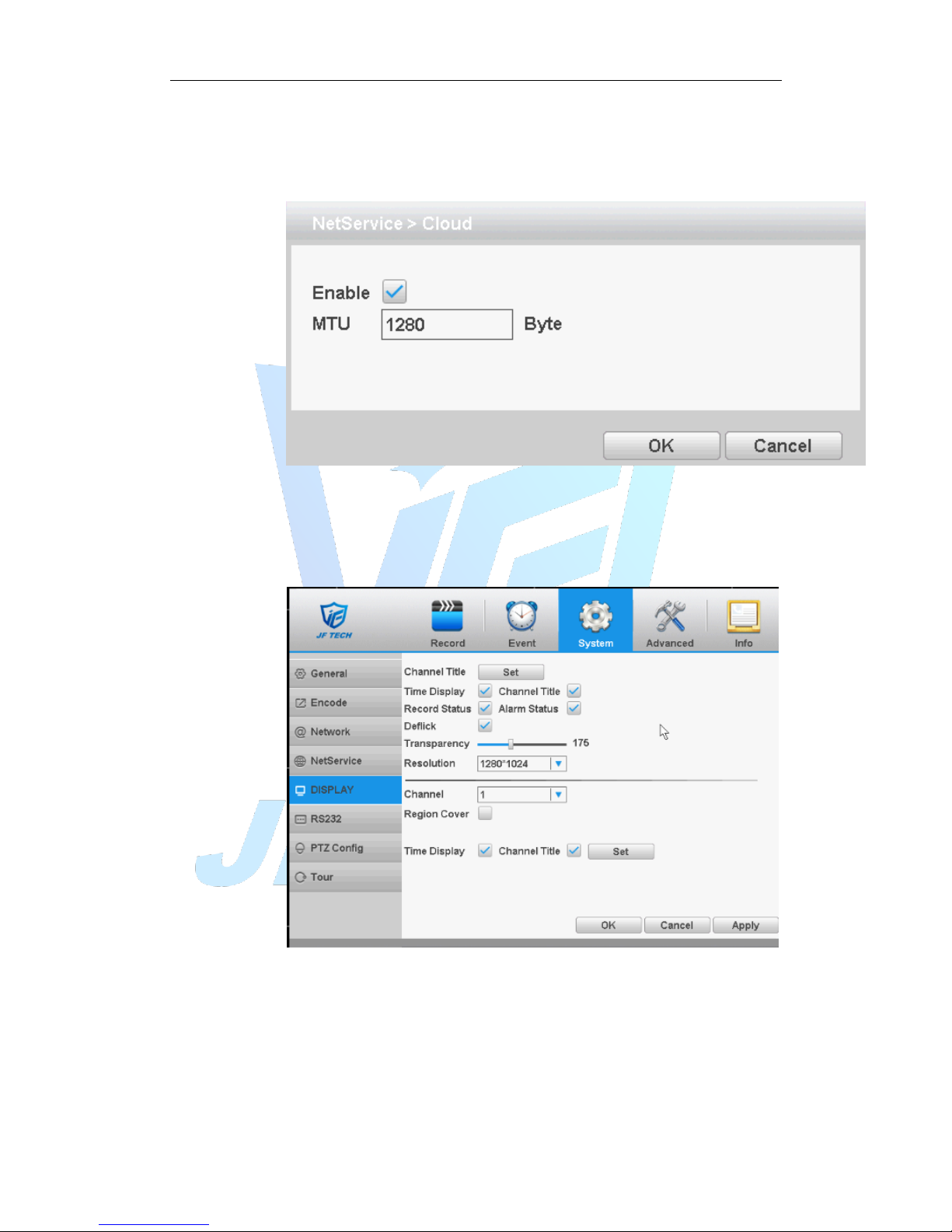
Check the cloud services, male cloud service is enabled, the user can visit
http://calDVRview.net/
Figure 4.30 Cloud
【Enable】 Select it to make sure abnormal function workable
4.4.5 GUI Display
Configure the video output parameters including time display, record status,
transparency, resolution etc.
Figure 4.31 GUI display
【Channel Title】Click the channel name modify button and enter the channel
name menu. Modify the channel name. The 16 Chinese characters and 25 letters
are supportive.
【Time Display】means the selective state. Display the system data and time in the
surveillance window.
【Channel display】means the selective state. Display the system channel number
Page 55
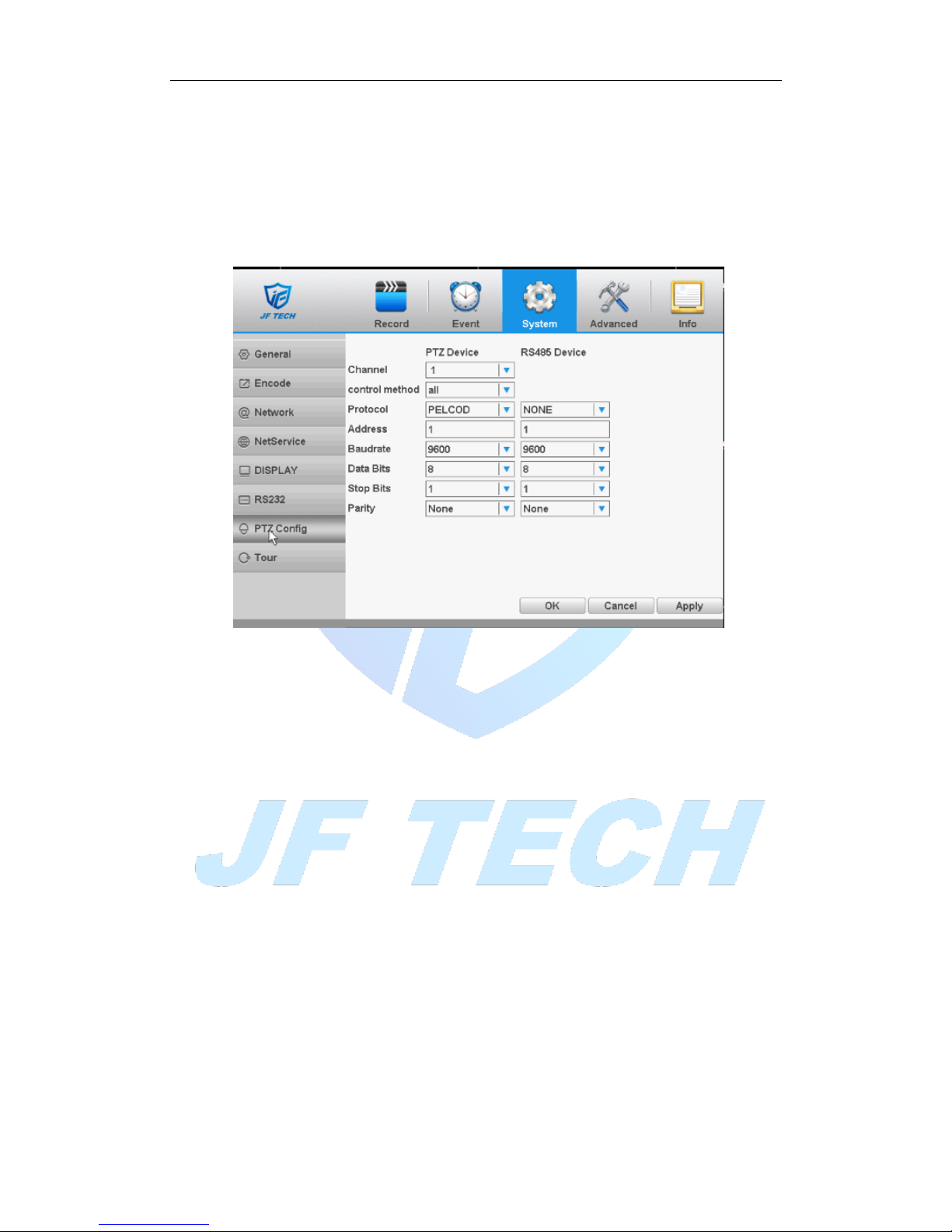
in the surveillance window.
【Alarm Status】means the selective state. Display the system alarm status in the
surveillance window.
【Transparency】Choose the background image transparency. The range is
128~255.
【Resolution】set display resolution.
4.4.6 RS485
Figure 4.32 RS485
[Protocols]to select the protocols (e.g.: Dahua);
[Address] set to the appropriate address, the default is 1;
[Baudrate] equipment used to select the appropriate baud rate, the default is
115200;
[Data bits], including 5-8 option, the default is 8;
[Stop bits] there are two options 1 and 2, the default is 1;
[Parity] points odd parity, even parity, mark parity, space parity, the default is
none.
4.4.7 port settings
* Some products do not support this feature
Page 56
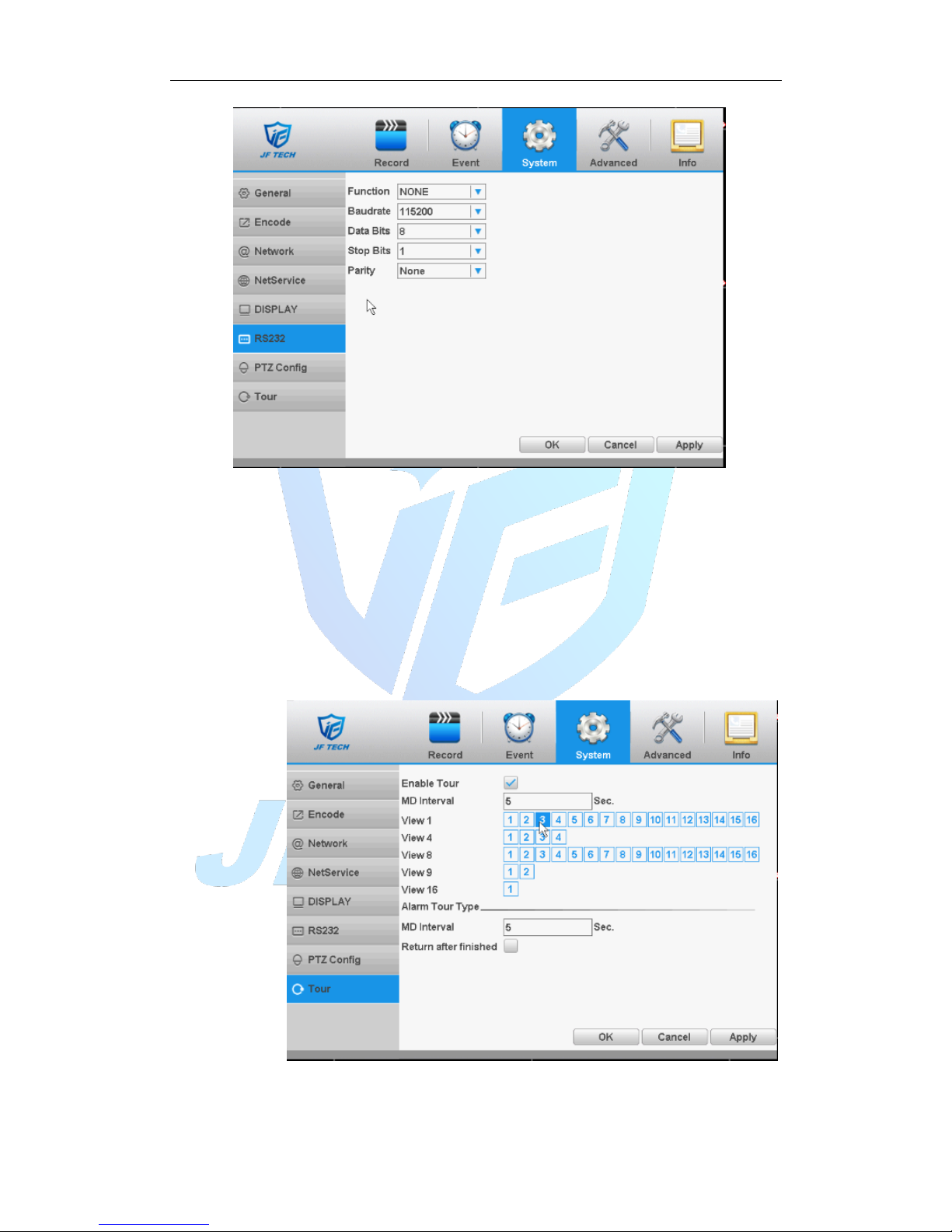
Figure 4.33 port settings
【Function】Common serial port is used to debug and update program or set up
specific serial port.
【Baudrate】Choose the corresponding baud rate length.
【Data bits】Include 5-8 options.
【Stop bits】Include 2 options.
【Parity】Include odd, even, mark, space, default is none.
4.4.8 Tour
Set the patrol display. Mean that the tour mode is enabled. You can choose the
single-view, four-view, six-view of single mode tour or hybrid mode tour.
Figure 4.34 touring settings
【MD Interval】Set the patrol switch interval. The set range is 5-120 seconds.
Page 57
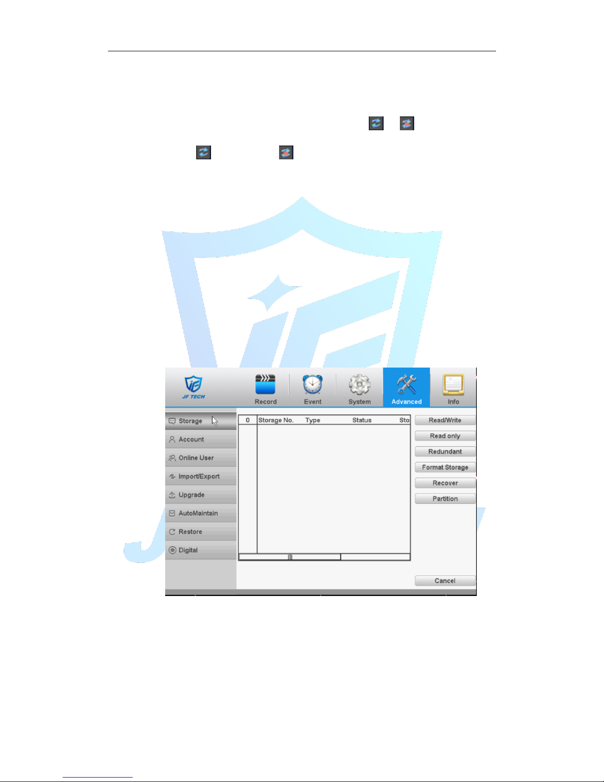
【Alarm Tour Type】set the interval to shift alarm tour, range is 5-120 seconds,
choose return when alarm ends, when alarm link to tour, system will auto shift to
six-view after alarm finished.
Remark:at preview mode, click upper right icon / can turn on / off
tour( mean turn on, mean turn off).
4.5 Advanced
Including Storage, Account, Online User, Import/Export, Upgrade, AutoMaintain, Restore,
Digital
4.5.1 Storage
Configure and manage the hard disk. The menu displays current hard disk information:
hard disk number, input port, type, status and overall capability. The operation include:
setup the write-read disk, read-only disk, redundant disk, hard disk format, resume
default. Choose the hard disk and click the right function button to execute.
Note:Read/Write Disk: The equipment can write or read data.
Read-only Disk: The equipment can read data but cannot write data.
Redundant Disk: Double backup the video files in the write-read disk.
Figure 4.35 Storage Management
4.5.2 Account
Manage the user purview.
Note:
1. The character length is 8 bytes at most for the following user and user team name.
The blank ahead or behind the character string is invalid. The middle blank in the
character string is valid. Legal characters include: letter, number, underline, subtraction
sign, and dot.
Page 58
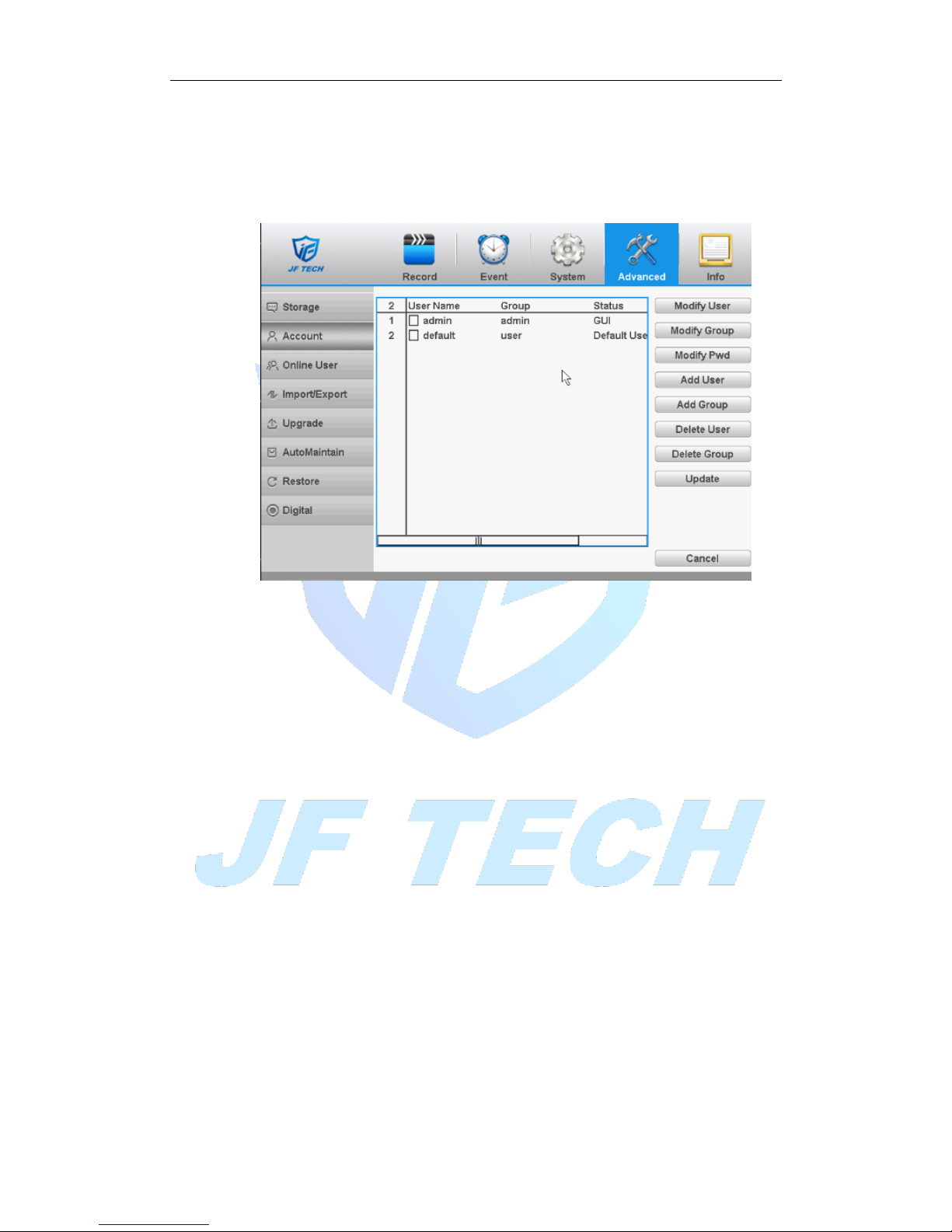
2. There is no limit in the user and user group. You can add or delete the user group
according to user definition. The factory setup include: user\admin. You can set the
team as you wish. The user can appoint the purview in the group.
3. The user management include: group/ user. The group and user name cannot be the
same. Each user only belongs to one group.
Figure 4.36 Account
[Modify User]: Modify the user name has been added, whether reuse, notes, group,
class, and permissions.
[Modify Group]: group name has been added to modify the user group, notes and
permissions.
[Modify Password]: modify user login password.
Note:The user who possess the user control purview can modify his/her own or
other users password
Page 59
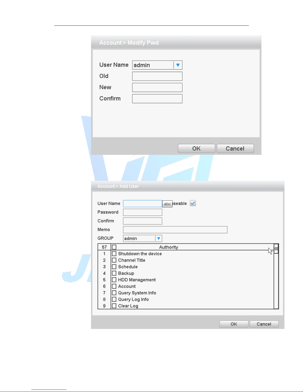
Figure 4.37 Modify password
[Add user]: Set new user name, password, notes, owning group, permissions and other
information, can add up to 64 user names.
Figure 4.38 Add user
[Add Group]: Set the group name new user group, notes, permissions and other
information.
Page 60
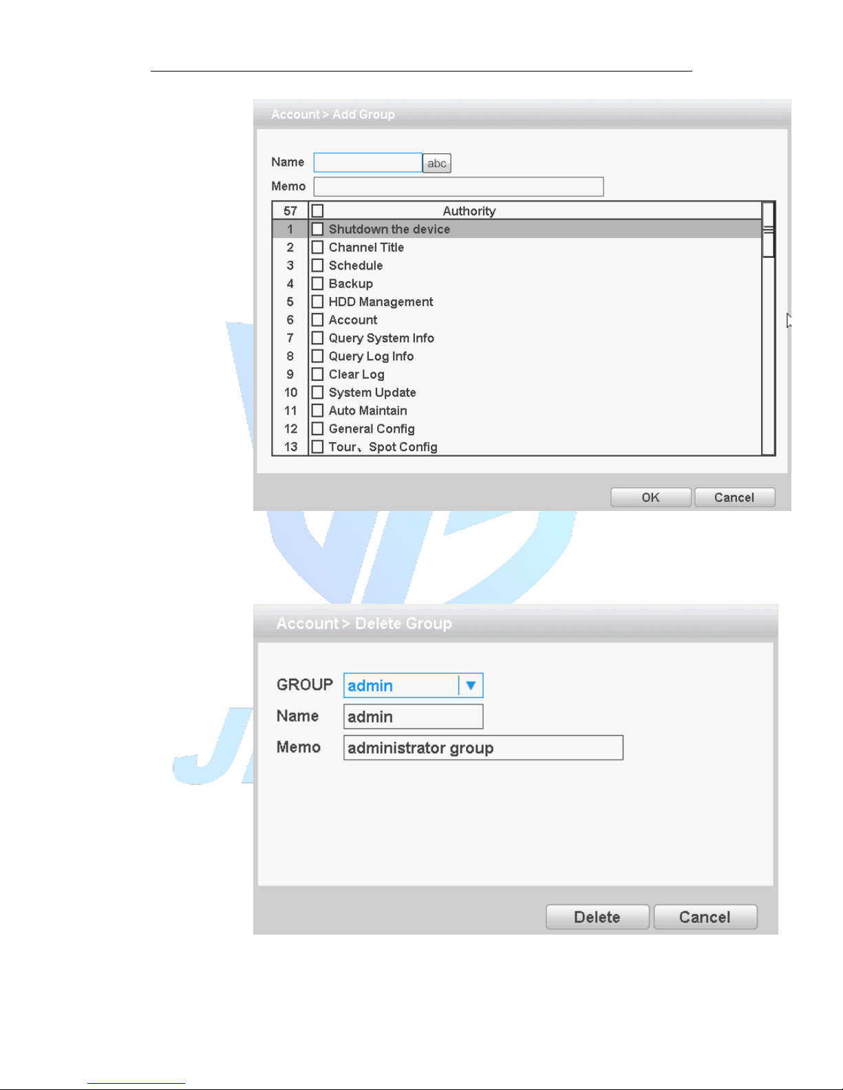
Figure 4.39 Add group
[Delete User]: delete the selected user, the user cannot delete the registry.
[Delete Group]: delete the selected user group, when the group contains a user group
cannot be deleted.
Figure 4.40 delete group
4.5.3 Online user
Page 61
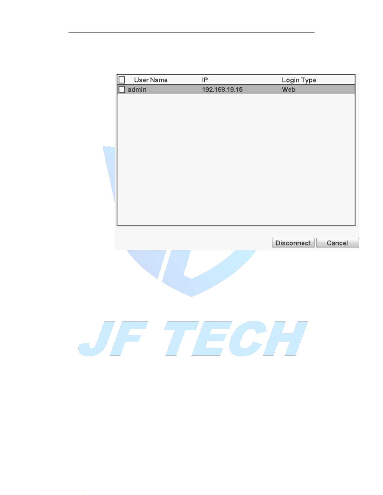
To check the information of network user that connected with local device, also can
tick the selected user to break up connection,(make √ at the box),then the user will
be frozen after connection stopped, and will not log in until device reboot.
Figure 4.41 Online user
4.5.4 Import / Export
Users can export the log info and the configure file from device to connected flash stick,
and also can import related configure file from flash stick to settings, which greatly
bring convenience to the customers.
Page 62
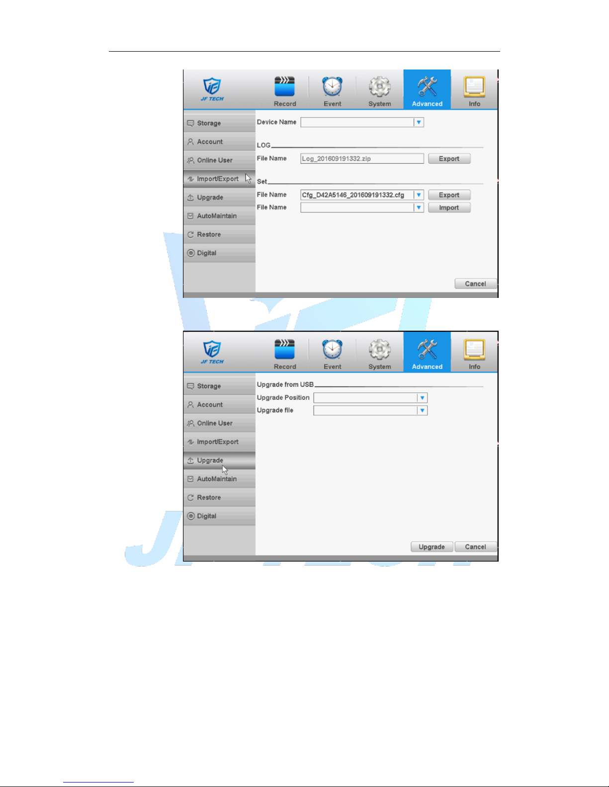
Figure 4.42 import/ export
4.5.5 Upgrade
Figure 4.43 Upgrade
【Upgrade】choose USB interface.
【Upgrade file】choose the upgrade file.
4.5.6 AutoMaintain
The user can set the time to auto reboot and auto delete file.
Page 63
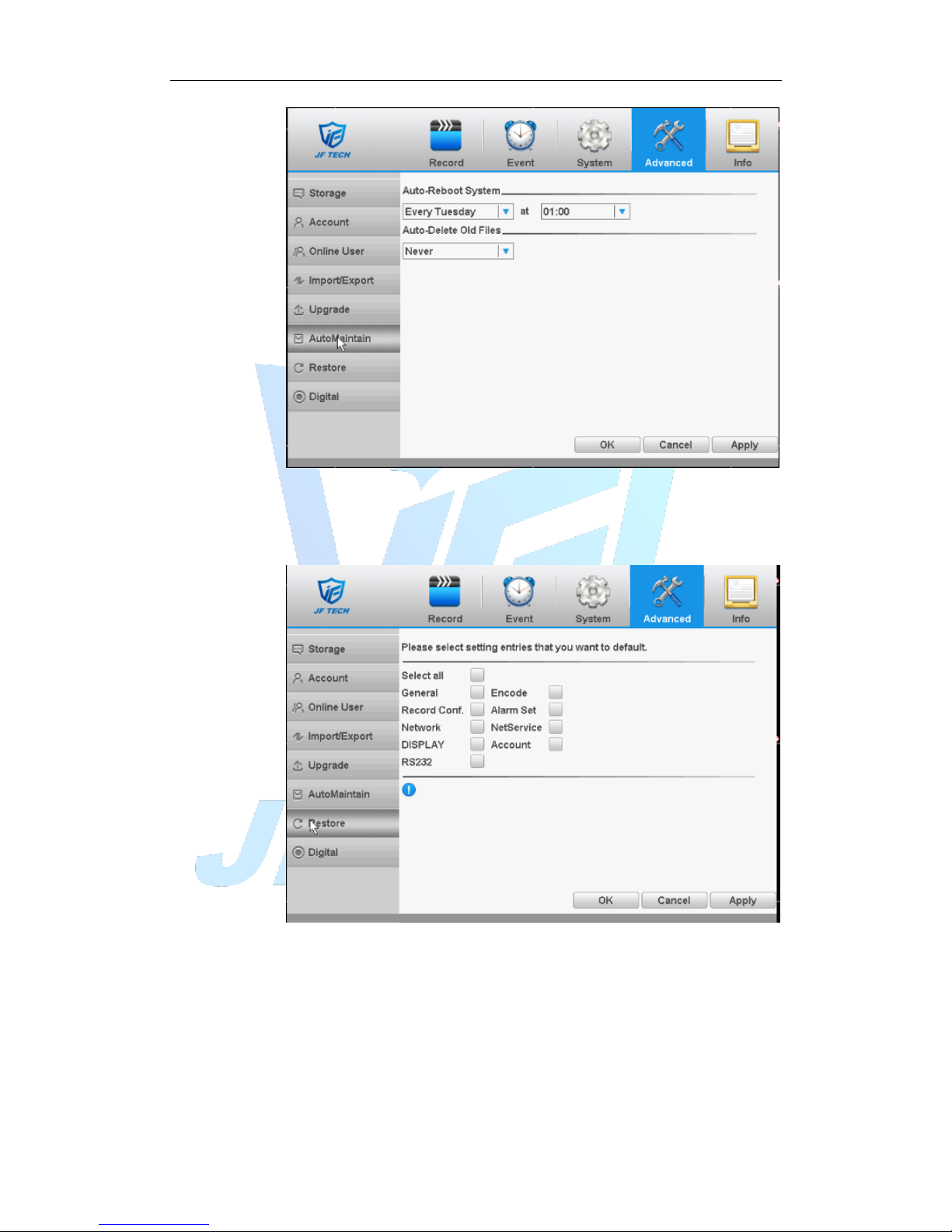
Figure 4.44 auto maintain
4.5.7 Restore
The system restore to the default. You can choose the items according to the
menu.
Figure 4.45 Restore
4.5.8 Channel manage
Channel management including digital channel, channel status, and channel
mode.(note: under full-analog mode, there is only channel mode selection)
Page 64
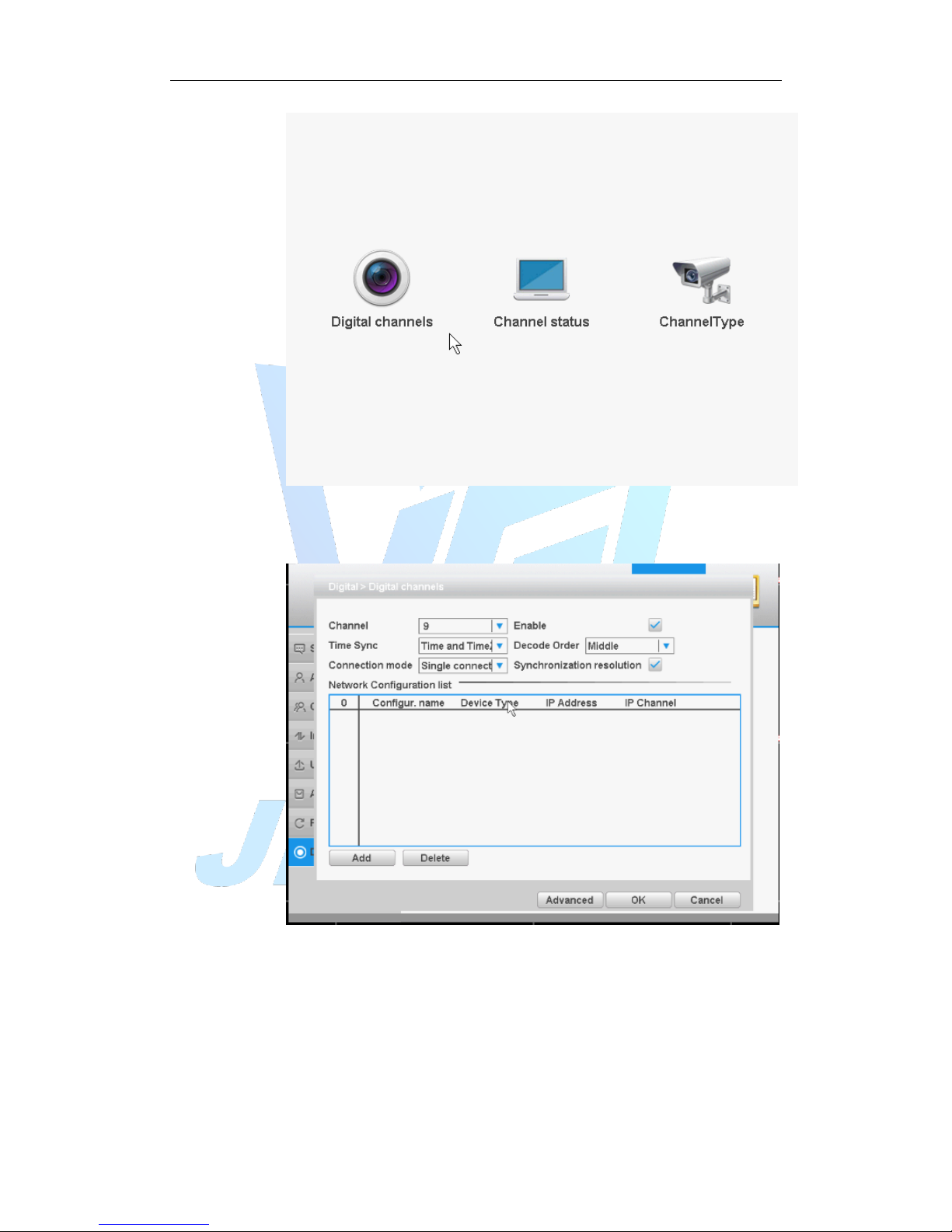
Mixed mode/ full-digital mode
Figure 4.46 channel manage
Digital channel
Figure 4.47digital channel
【Channel】select channel title
【Enable】Open digital channel, tick enable, then can do related settings
【Time Sync】Tick it means the time of this channel and device is the same.
【Connection Mode】can be singe connect or multi-ink, multi-link modes can
connect to several devices, device will be tour displayed one by one, tour interval
can be set, no less then 10s;
【Delete】If the user want to change device, select the existing device, click delete
Page 65
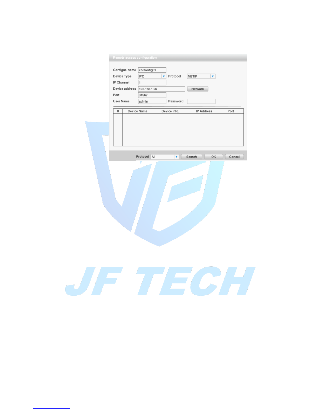
will be ok.
【Add】click add will come out below page to add new device
Figure 4.48 Remote access configurations
【Configure Name】device is with default configure title, user can revise it if
necessary;
【Device Type】3 types: IPC、DVR、HVR,user can choose as what you like, default
is IPC;
【Protocol】There are two protocols: NTEIP and ONVIF, the default is NETIP;
【IP channel】User can input remote channel title from the device that you want
to connect remotely;
【Device Address】to enter remote device IP, the system defaults to 192.168.1.20;
【Port】Default is 34567
【User name】Default is admin
【password]】default is blank
Note:
1. In Figure 4.47, the protocol search drop-down box on the left side, there are
three, namely NETIP, ONVIF, the whole, the user can choose according to demand,
click search it will search for the corresponding protocol online device.
2. Click the Search button, the following will show the device as shown in the
search to 4.48, the user can double-click the device IP connections want according
to their needs, and you can add the device. At this point in Figure 4.47 device
address and port the appropriate changes, and the user name and password is still
the default parameters, the user must be entered manually.
3. Double-click the discovered devices, network setup in Figure 4.47 by graying
light, click the button; you can just add the device to the network settings shown
in Figure 4.48.
Page 66
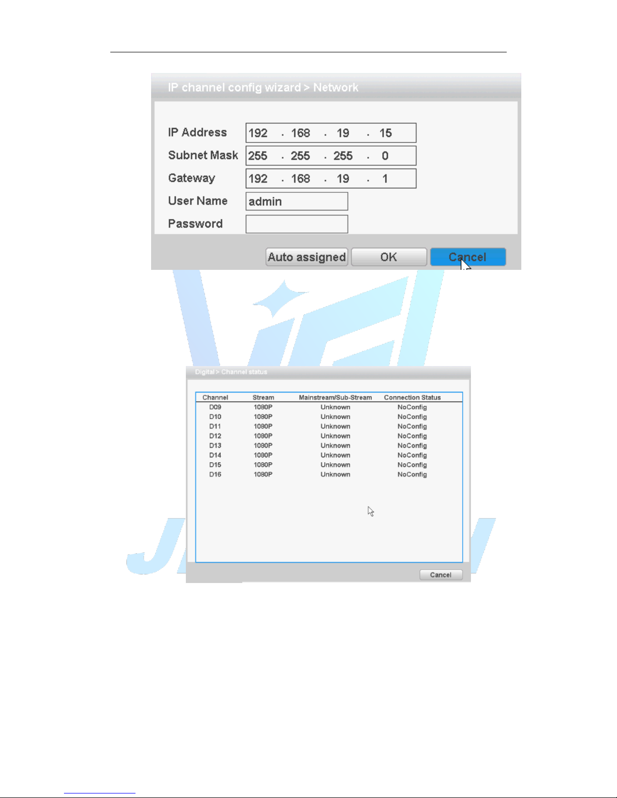
Figure 4.49 network settings
Channel Status:
Channel status is to show the status of the entire digital channel when there is what
existing, status including Max Resolution, This Resolution, and Connection Status.
The channel status as 4+2 mode:
Figure 4.50 Channel Status
Remark: when the current resolution is over the max resolution that the channel
supported, then a red “X” will be shown on the preview image, for example: Under
full digital channel mode, Max resolution of channel 3 is D1, if it was connected to a
device with resolution over D1 ( such as 960H).
Channel mode:
Page 67
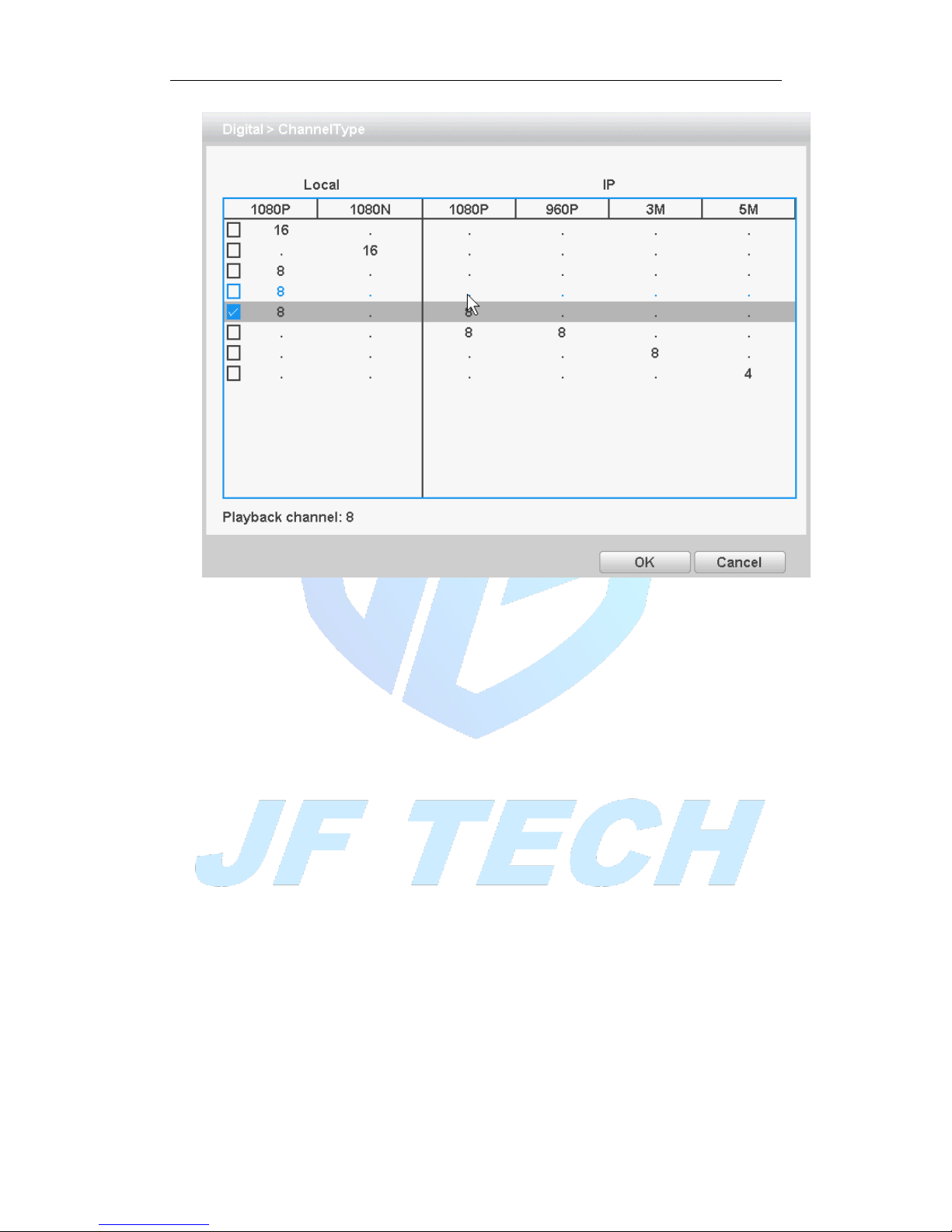
Figure 4.51Channel Type
Remark: this series of product with full analog channel mode, hybrid mode and full
digital mode, and different model with different channel mode, user can shift the
mode freely if necessary.
4.6 System Info
Display the hard disk information, including HDD info, code stream statistic, log info,
version info.
4.6.1 HDD info
Display the hard disk state: hard disk type, overall capability, residual capability, the
recording time and so on.
.
Page 68
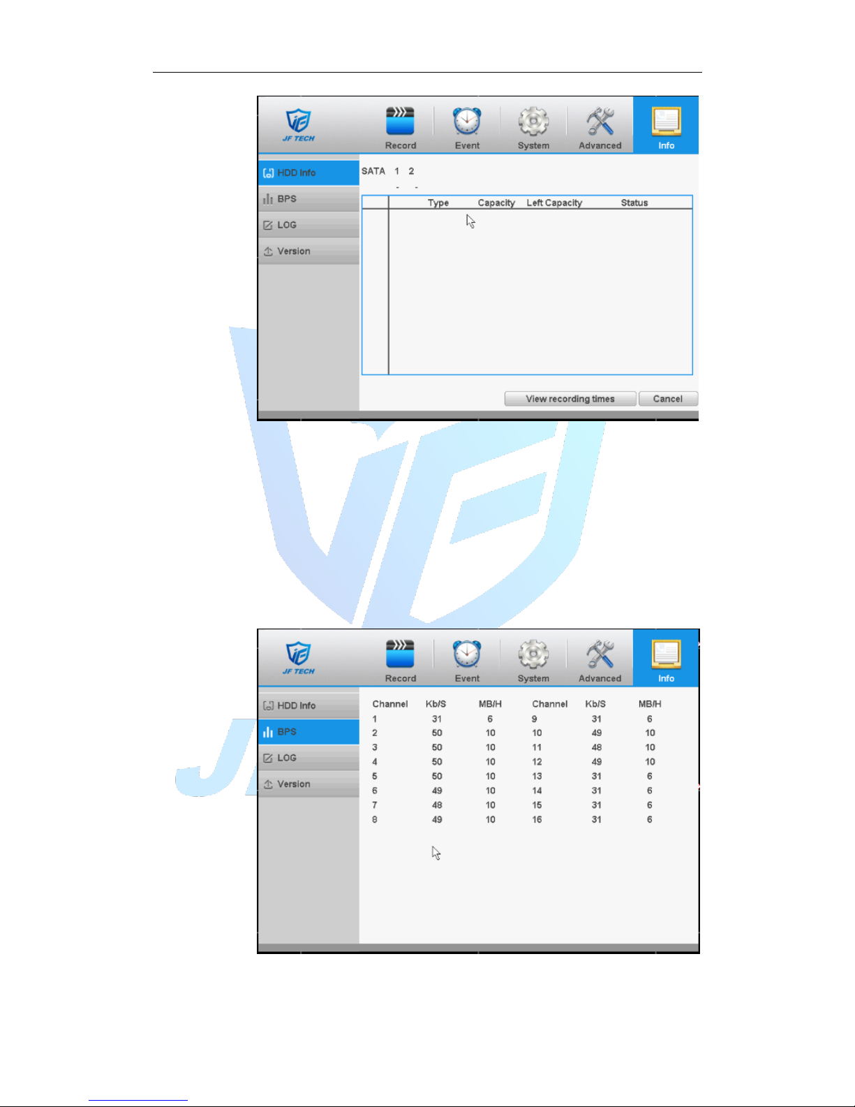
Figure 4.52HDD info
Tips:○ means that the hard disk is normal. X means that the hard disk is broken-down.-
means that there is no hard disk. If the user needs to change the damaged hard disk,
you must shut down the DVR and take up all the damaged hard disks, then install a new
one.
* Behind serial number means the current working disk such as 1*. If the
corresponding disk is damaged, the information will show “?”
4.6.2 BPS
Display the code stream(Kb/S)and hard disk capability (MB/H)in real time. It displays
as the wave sketch map.
Figure 4.53 BPS
4.6.3 LOG
Page 69
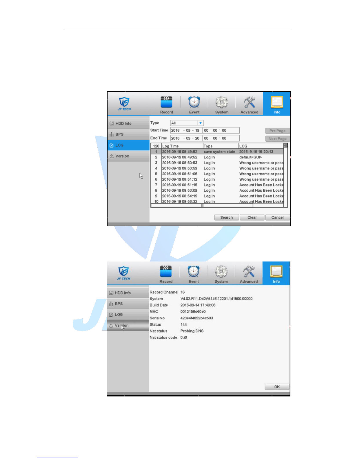
To search log information base on the set search mode.
Log information include: system operation, configuration operation, data management,
alarm affair, recording operation, user management, and file management and so on.
Set the time section to look up and click the look up button. The log information will
display as a list. (One page is 128 items) Press Page up or Page down button to look up
and press delete button to clear all the log information.
Figure 4.54 LOG
4.6.4 Version
Display the basic information such as hardware information, software version, issue
date, serial number, and NAT status and so on.
Figure 4.55 version
Page 70

4.7 Shut down system
Refer to chapter 3.5.8.
Page 71
5. Remote Cloud Operating Instructions
5.1 Cloud surveillance
Cloud technology allows the device to achieve one step to Internet, which greatly facilitates the
customers to monitor the public network. The technology access the device through the serial
number.
* Note: Support for cloud technology equipment required to be in the public domain is
available within the cloud monitoring.
5.1.1 Check the cloud connection status
After the device is connected to external networks, you can check through [main menu]>
[System]> [Version],If the Nat Status is “Connected”,then it means the device is connecting to the
cloud server successfully.
5.1.2 Log in cloud server
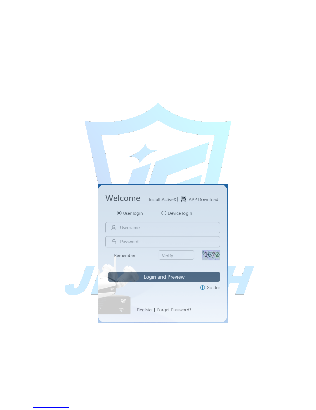
Log http://cloud.jufenginfo.com, Pop up the login screen, which has login by user and log in
by the device two ways, the customer can demand their own choices login.
* Note: The first time according to login by user, you need to register.
Figure 5.1 Log in
5.1.3 Log in by user
After the customer entering username and password, the following screen pops up:
Page 72
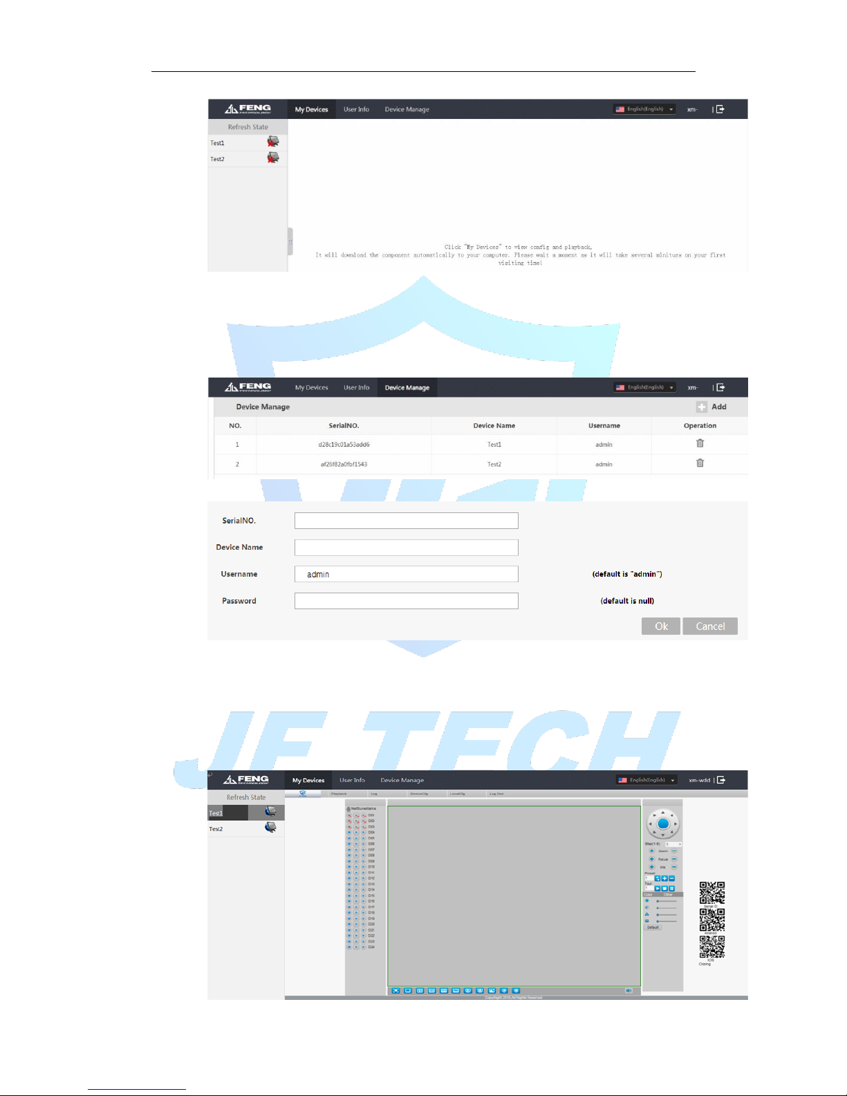
Figure 5.2 cloud technology interface
Device Management:
Mainly used to add devices to be monitored, click Add, to add serial number of the
device.
Figure 5.3 device management
Figure 5.4Add device
* Note: the user name in Figure 5.5 is the user name of monitoring equipment; device
password refers to the appropriate device user's password.
My device:
The main display device name added to the Device Manager, click on the success of the
devices connected to the server name, you can access to monitor the device.
Page 73
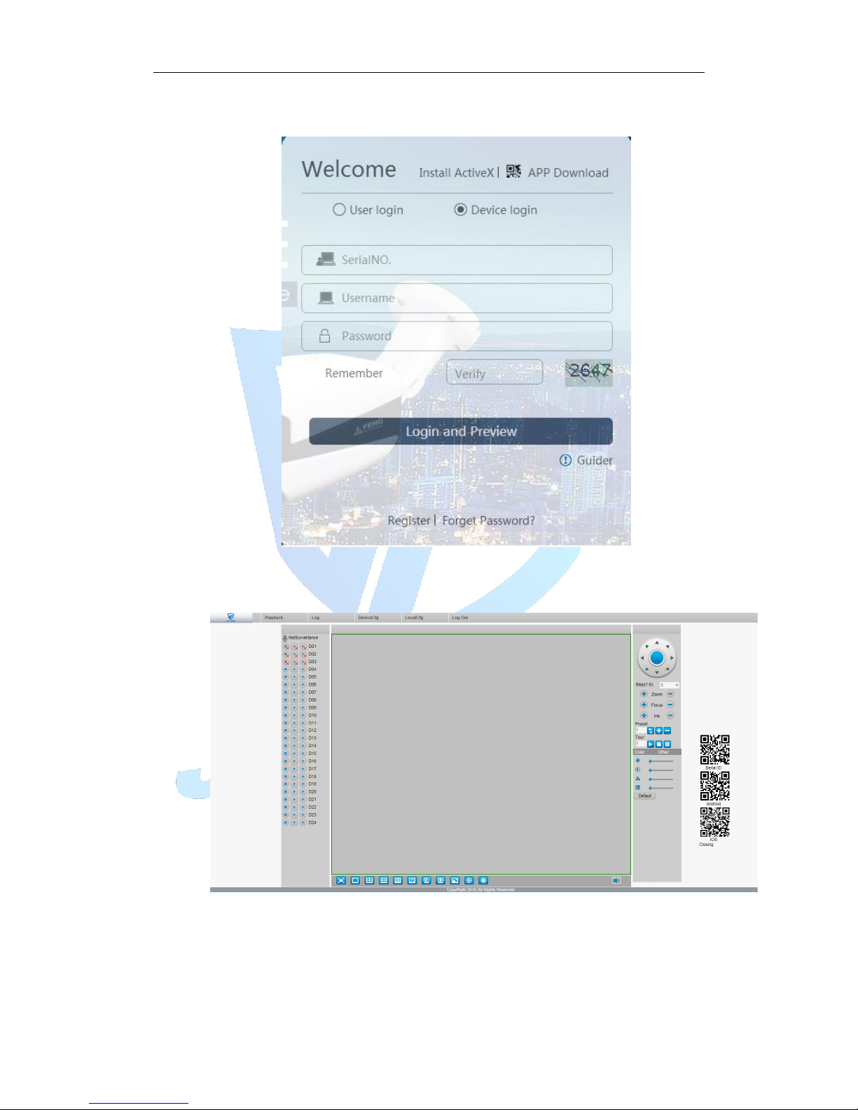
Figure 5.5 surveillance screen
5.1.4 Log in by device
Figure 5.6 log in by device
Enter the serial number of the device to monitor and verify the code after the direct
monitoring equipment.
Figure 5.7 surveillance screen
Page 74

6. FAQ and maintenance
6.1 FAQ
If your problem is not the content of the following, please contact your local customer
service staff or call the customer service consulting headquarters, we will be happy to
serve you.
Q: When turned on, the DVR does not start properly
A: Possible reasons:
Input power is not correct
Switching power line contact is not good
Switching Power Supply bad
Program Upgrade Error
Hard disk is damaged or hard-line issue
Front panel fault
DVR bad motherboard
Q: A few minutes after starting the DVR will automatically reboot or frequent crashes
A: Possible reasons:
Input voltage is unstable or too low
Hard disk has bad sectors or bad hard line
Switching power supply power is not enough
Front-end video signal instability
Adverse heat, too much dust, the machine is too harsh operating
environment
DVR hardware failure
Q: System cannot detect hard disk.
A: Possible reasons are as followed:
The hard disk power supply line is not connected.
The cables of the hard disk are damaged.
The hard disk is damaged.
The SATA port of main board is damaged.
Q: There are no video outputs in single channel, multiple channels and all channels.
A: Possible reasons are as followed:
The program is not matched. Please update the program.
The image brightness is all 0. Please restore the default setup.
There is no video input signal or the signal is too weak.
The channel protection or the screen protection is set.
The hardware of the DVR is damaged.
Q: I cannot find the video files in local playback mode.
A: Possible reasons are as followed:
The data line of the hard disk is damaged.
The hard disk is damaged.
Page 75

Update the different program with the origin program files.
The video files to look up are covered.
The recording is not on.
Q: The local video is not clear.
A: Possible reasons are as followed:
The image quality is too bad.
The reading program is wrong. Reboot up the DVR.
The data line of the hard disk is damaged.
The hard disk is damaged.
The hardware of the DVR is damaged.
Q: There is no audio signal in the surveillance window.
A: Possible reasons are as followed:
It is not an active tone arm.
It is not an active sound box.
The audio lines are damaged.
The hardware of the DVR is damaged.
Q: There is audio signal in the surveillance window but mo audio signal in the
playback state.
A: Possible reasons are as followed:
Setting issues: the audio option is not chosen.
The according channel is not connected with the video.
Q: The time is wrong.
A: Possible reasons are as followed:
Setting is wrong..
The battery is in bad connection or the voltage is too low.
The oscillation is damaged.
Q: The DVR cannot control the PTZ.
A: Possible reasons are as followed:
There is something wrong with the frontal PTZ.
The setting, connection or the installation of the PTZ decoder is not correct.
The connections are not correct.
The PTZ setting of the DVR is not correct.
The protocols of the PTZ decoder and the DVR are not matched.
The address of the PTZ decoder and the DVR are not matched.
When multiple decoders are connected, the far port of the PTZ decoder line
A(B) must connect a 120 resistance to reduce the reflection otherwise the PTZ
control is not stable.
The distance is too far.
Q: the motion detect is not working,
A: Possible reasons are as followed:
The time range set is not correct.
The motion detect area set is not correct.
The sensitivity is too low.
Limited by some hardware edition.
Page 76

Q: I cannot login via web or CMS.
A: Possible reasons are as followed:
The system is Windows98 or Winme. We recommend updating to windows
2000sp4 or higher Version or installing the software for low edition.
ActiveX is hold back.
The version is not exceeded dx8.1. Update the display card driver.
Network connection failure.
Network setting issues.
Invalid password or user name.
The CMS is not matched the DVR program version.
Q: The image is not clear or there is no image in network preview state or video file
playback state.
A: Possible reasons are as followed:
Network is not stable.
The user machine is resource limited.
Choose the play-in-team mode in the network setup of DVR.
The region shelter or channel protection is set.
The user has no surveillance purview.
The real-time image of the hard disk recording machine itself is not clear.
Q: Network connection is not stable.
A: Possible reasons are as followed:
Network is not stable.
IP address is conflicted.
MAC address is conflicted.
The net card of the DVR is bad.
Q: There is something wrong with the USB backup or writing a CD.
A: Possible reasons are as followed:
The rewritable machine and the hard disk are shared the same data lines.
The data is too much. Please stop recording and backup.
The data exceeds the backup storage.
The backup equipment is not compatible.
The backup equipment is damaged.
Q: The keyboard cannot control the DVR.
A: Possible reasons are as followed:
The serial port of the DVR is not set correctly.
The address is not correct.
When multiple transformers are connected, the power supply is not large
enough. Please give each transformer individual power supply.
The distance is too far.
Q: Alarm cannot be recessional.
A: Possible reasons are as followed:
The setting of the alarm is not correct.
The alarm output is turned on manually.
The input machine is damaged or the connections are not correct.
Page 77

There are some problems for specific program edition, Please update the
program.
Q: Alarm is not working.
A: Possible reasons are as followed:
The setting of the alarm is not correct.
The connection of the alarm is not correct.
The alarm input signal is not correct.
A alarm is connected with two loops synchronously.
Q: the remote controller is not working,
A: Possible reasons are as followed:
The remote control address is not correct.
The remote control distance is too far or the angle is too large.
The battery is used up.
The remote controller or the front panel of the recording machine is
damaged.
Q: The storage time is not enough.
A: Possible reasons are as followed:
Front vision quality is bad. The lens is too dirty. The Videocon is in
backlighting installation.
The hard disk capability is not enough.
The hard disk is damaged.
Q: The downloading files cannot play.
A: Possible reasons are as followed:
There is no media player.
There is no DX8.1 software or higher edition.
There is no DivX503Bundle.exe file to play AVI video files.
The DivX503Bundle.exe and ffdshow-2004 1012 .exe files must be installed in
the windows xp system.
Q: I cannot remember the advanced password or network code in the local menu
operation.
A: Please contact the local service or call the HQ service. We will offer the service
according the machine type and the program edition.
Q: Cannot see the preview picture the digital channel
A: Possible reasons are as followed:
Did not add device
The device of related channel was not enable
The device of related channel was not selected.
The selected device did not connect to video sources
The channel title of selected remote device is not exist.
Stream for remote channel was set by extra stream.
User name & password not matched
Directly input with IP address or port No. incorrectly when adding device.
The resolution of added device is too large to display by the monitor.
Q: Click “search” why not search out any of the device.
Page 78

A: Possible reasons are as followed:
There is no other device exist in the Local area network
The subnet masks setting incorrectly on Network settings.
Q: The snapshot at alarm function was enable, why not catch picture
A: Possible reasons are as followed:
HDD manage without partition for snapshot.
Partition for snapshot is 0
The snapshot function is not enabled on record-> storage of related channel.
Q: The time shows on digital channel is not the same as local side:
A: Enable the time synchronous function of digital channel.
Q: Cannot see preview picture of analog channel
A: Possible reasons are as followed:
The camera did not connect to video interface
The device did not connect to video source
Video source is broken.
Q: Picture will be frozen when multi-connection and shift devices.
A: Picture come out from digital channel need few seconds, shift device means to show
new picture, so it needs several seconds to buffer.
6.2 Maintenance
1. Please brush printed circuit boards, connectors, fans, machine box and so on
regularly.
2. Please keep the grounding well done to prevent the video or audio signal
interfered and the DVR from static or inductive electricity.
3. Do not pull out the video signal line or RS-232 port or RS-485 port with the power
on.
4. Do not use the TV in the local video output port(VOUT) of DVR. It will damage the
video output circuit easily.
5. Do not turn off the switch directly. Please use the turn-off function in the menu or
press the turn-off button in the panel (3 seconds or longer) to protect the hard
disk.
6. Please keep the DVR away from heat resource.
7. Please keep the DVR ventilated for better heat radiator.
8. Please check the system and maintain regularly.
Page 79

Page 80
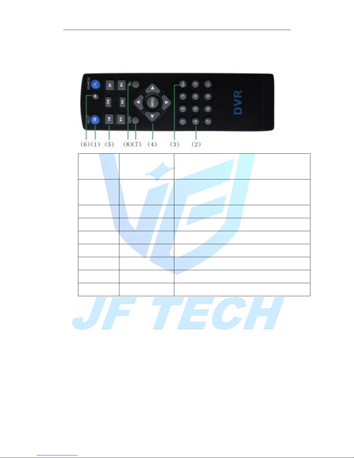
Appendix Ⅰ Remote controller operation
Serial
number
Name
Function
1
Multi-window
button
Same function as Multi-window button in the front
panel 2 Numeric button
Code input/number input/channel switch
3
【Esc】
Same function as【Esc】button in the front panel
4
Direction button
Same function as direction button in the front panel
5
Record control
Control the record
6
Record mode
Same function as “Record mode”
7
ADD
Input the number of DVR to control it
8
FN
Assistant function
Page 81

Appendix Ⅱ Mouse operation
*Take right hand as an example
The mouse in USB connection is supported.
Operation
Function
Double left click
Double click one item in the file list to playback the
video
Double click the playback video to zoom in or out the
screen
Double click the channel to make it full screen display
double click again to resume the multi-window display
Left click
Choose the according function in the menu
Right click
Pop desktop shortcut menu in preview state
Current shortcut menu in the menu
Press middle
button
Add or subtract number in the number setting
Switch the items in the combo box
Page up or down in the list
Move mouse
Choose the widget or move the item in the widget
Drag mouse
Set the motion detect area
Set the cover area
Page 82

Appendix Ⅲ Hard disk capability calculation
Make sure the hard disk installed to the DVR for the first time. Pay attention to the
IDE hard disk lines connection.
1、 Hard disk capability
There is no limit for recording machine. We recommend 120G~250G size to
keep better stability.
2、 Overall capability option
The hard disk capability formula is:
Overall capability(M)=channel number*time(hour)*capability in an hour(M/hour)
The recording time formula is:
Recording time(hour)=
overall capability(M)
Capability in an hour(M/hour)*channel number
The DVR introduces the H.264 compression technology. Its dynamic range is
very large so the hard disk capability calculation is based on the estimation values of
each channel creating files in an hour.
Example:
For one piece 500G HDD, real time CIF for recording, it will keep recording for about 25
days.HDD spaces per channel is 200M/H, If 4channels real time CIF at 24hours recording
uninterrupted, it can last: 500G/(200M/H*24H*4ch)=26 days
 Loading...