

Jetway V4MDFTR1A User Manual

V4MDF/V4MDFT
USER'S MANUAL
M/B For Socket-A Athlon/Duron Processor
NO. G03-V4MDFT
Rev:1.0
Release date: December 2003
Trademark:
* Specifications and Information contained in this documentation are furnished for information use only, and are
subject to change at any time without notice, and should not be construed as a commitment by manufacturer.

TABLE OF CONTENT
USER’S NOTICE..................................................................................................................... ii
MANUAL REVIS1ION INFORMATION ............................................................................ ii
COOLING SOLUTIONS........................................................................................................ ii
CHAPTER 1 INTRODUCTION OF V4MDF/V4MDFT MOTHERBOARD
1-1 FEATURE OF MOTHERBOARD.......................................................................... 1
1-2 SPECIFICATION .....................................................................................................2
1-3 PERFORMANCE LIST ...........................................................................................3
1-4 LAYOUT DIAGRAM & JUMPER SETTING ......................................................4
CHAPTER 2 HARDWARE INSTALLATION
2-1 HARDWARE INSTALLATION STEPS ................................................................ 7
2-2 CHECKING MOTHERBOARD'S JUMPER SETTING......................................7
2-3 INSTALL CPU ..........................................................................................................8
2-3-1 GLOSSARY ...................................................................................................8
2-3-2 ABOUT AMD ATHLON & DURON 462-PIN CPU.................................. 9
2-4 INSTALL MEMORY ............................................................................................... 10
2-5 EXPANSION CARD ................................................................................................. 11
2-5-1 PROCEDURE FOR EXPANSION CARD INSTALLATION .................. 11
2-5-2 ASSIGNING IRQ FOR EXPANSION CARD ............................................ 11
2-5-3 INTERRUPT REQUEST TABLE FOR THIS MOTHERBOARD.......... 12
2-5-4 AGP SLOT ..................................................................................................... 12
2-6 CONNECTORS, HEADERS.................................................................................... 12
2-6-1 CONNECTORS ............................................................................................. 12
2-6-2 HEADERS ......................................................................................................15
2-7 STARTING UP YOUR COMPUTER..................................................................... 19
CHAPTER 3 INTRODUCING BIOS
3-1 ENTERING SETUP.................................................................................................. 20
3-2 GETTING HELP....................................................................................................... 20
3-3 THE MAIN MENU ................................................................................................... 21
3-4 STANDARD CMOS FEATURES............................................................................ 22
3-5 ADVANCED BIOS FEATURES .............................................................................23
3-6 ADVANCED CHIPSET FEATURES ..................................................................... 25
3-6-1 DRAM TIMING SETTINGS........................................................................26
3-6-2 AGP FUNCTION SETTING ........................................................................ 27
3-6-3 PCI TIMING SETTINGS............................................................................. 27
3-7 INTEGRATED PERIPHERALS............................................................................. 28
3-7-1 ONCHIP IDE FUNCTION ...........................................................................28
3-7-2 ONCHIP DEVICE FUNCTION................................................................... 29
3-7-3 ONBOARD SUPER IO FUNCTION ........................................................... 30
3-8 POWER MANAGEMENT SETUP .........................................................................31
3-8-1 WAKE UP EVENTS .....................................................................................32
3-8-1.1 IRQS ACTIVITIES ....................................................................................33
3-9 PNP/PCI CONFIGURATION SETUP ................................................................... 33
3-9-1 IRQ RESOURCES ........................................................................................34
3-10 PC HEALTH STATUS............................................................................................ 34
3-11 MISCELLANEOUS CONTROL ...........................................................................35
3-12 LOAD STANDARD/OPTIMIZED DEFAULTS ..................................................36
3-13 SET SUPERVISOR/USER PASSWORD .............................................................. 36
CHAPTER 4 DRIVER & FREE PROGRAM INSTALLATION
MAGIC INSTALL SUPPORTS WINDOWS 95/98/98SE/NT4.0/2000/XP ...................37
4-1 VIA 4 IN 1
4-2 VGA
4-3 SOUND
4-4 LAN
4-5 PC-HEALTH
4-6 USB2.0
4-7 PC-CILLIN
INSTALL VIA SERVICE PACK 4 IN 1 DRIVER
INSTALL VIA VGA DRIVER
INSTALL
INSTALL RTL810X LAN CONTROLLER DRIVER
INSTALL MY GUARD FOR VIA8237 UTILITY
INSTALL VIA USB2.0 DEVICE DRIVER
INSTALL PC-CILLIN 2004 ANTI-VIRUS PROGRAM
ALC
AUDIO CODEC DRIVER
..........................................................39
........................................43
.............................38
.......................................40
.......................41
.............................42
....................44
4-8 HOW TO DISABLE ON-BOARD SOUND............................................................ 45
4-9 HOW TO UPDATE BIOS........................................................................................ 45
CHAPTER 5 INSTALLATION OF MagicTwin .................................................................46
5-1 INSTALLATION OF MagicTwin (A 2-User-System Solution) ...........................46
i

USER’S NOTICE
COPYRIGHT OF THIS MANUAL BELONGS TO THE MANUFACTURER. NO PART OF THIS MANUAL,
INCLUDING THE PRODUCTS AND SOFTWARE DESCRIBED IN IT MAY BE REPRODUCED,
TRANSMITTED OR TRANSLATED INTO ANY LANGUAGE IN ANY FORM OR BY ANY MEANS WITHOUT
WRITTEN PERMISSION OF THE MANUFACTURER.
THIS MANUAL CONTAINS ALL INFORMATION REQUIRED TO USE V4MDF/V4MDFT MOTHER-BOARD
AND WE DO ASSURE THIS MANUAL MEETS USER’S REQUIREMENT BUT WILL CHANGE, CORRECT
ANY TIME WITHOUT NOTICE. MANUFACTURER PROVIDES THIS MANUAL “AS IS” WITHOUT
WARRANTY OF ANY KIND, AND WILL NOT BE LIABLE FOR ANY INDIRECT, SPECIAL, INCIDENTIAL
OR CONSEQUENTIAL DAMAGES (INCLUDING DAMANGES FOR LOSS OF PROFIT, LOSS OF BUSINESS,
LOSS OF USE OF DATA, INTERRUPTION OF BUSINESS AND THE LIKE).
PRODUCTS AND CORPORATE NAMES APPEARING IN THIS MANUAL MAY OR MAY NOT BE
REGISTERED TRADEMARKS OR COPYRIGHTS OF THEIR RESPECTIVE COMPANIES, AND THEY ARE
USED ONLY FOR IDENTIFICATION OR EXPLANATION AND TO THE OWNER’S BENEFIT, WITHOUT
INTENT TO INFRINGE.
Manual Revision Information
Reversion Revision History Date
1.0 First Release Dec. 2003
Item Checklist
5
V4MDF/V4MDFT Motherboard
5
Cable for IDE/Floppy
5
CD for motherboard utilities
□
Y-Cable for 2-Keyboard/2-Mouse (only for V4MDFT)
5
Cable for Serial-ATA
5
V4MDF/V4MDFT User’s Manual
AMD Athlon™ / Duron™ Processor Family
Cooling Solutions
As processor technology pushes to faster speeds and higher performance, thermal management
becomes increasingly crucial when building computer systems. Maintaining the proper thermal
environment is key to reliable, long-term system operation. The overall goal in providing the proper
thermal environment is keeping the processor below its specified maximum case temperature.
Heatsinks induce improved processor heat dissipation through increased surface area and
concentrated airflow from attached fans. In addition, interface materials allow effective transfers of
heat from the processor to the heatsink. For optimum heat transfer, AMD recommends the use of
thermal grease and mounting clips to attach the heatsink to the processor.
When selecting a thermal solution for your system, please refer to the website below for collection of
heatsinks evaluated and recommended by AMD for use with AMD processors. Note, those heatsinks
are recommended for maintaining the specified Maximum T case requirement. In addition, this
collection is not intended to be a comprehensive listing of all heatsinks that support AMD processors.
For vendor list of heatsink and fan, please visit:
http://www1.amd.com/products/duron/thermals
http://www1.amd.com/products/athlon/thermals
ii

Chapter 1
Introduction of V4MDF/V4MDFT Motherboard
1-1 The 2-User Motherboard V4MDFT
The special designed 2-user motherboard (V4MDFT) allows two users to share the computing
power of a single PC system. With integrated connectivity hardware onboard, the
motherboard comes with innovative software, the MagicTwin®, allowing 2 users to be
connected to it and runs up to two stations directly from it simultaneously. The unique and
copyright-protected MagicTwin® technology makes each of the 2 users feel like having
himself his own Windows-XP computer. Each user needs to have himself his own keyboard,
mouse, sound device, and monitor. All remaining PC hardware are shared, even the IP.
Both users can operate on their own station concurrently just like the operation of a standard
PC. There is no obvious delay because of the Time-slicing/Multiplexing technology built-in.
Each user gets an exact and extremely short defined moment to access to the PC system,
devices, applications and Windows itself. Resources are only claimed for nanoseconds at a
time, usually from electronic memory, or cache. Both users get from Windows and the PC,
what they really need when they need it! The MagicTwin solution turns the single PC into a
cost-effective multi-user system.
The setup is intuitive and easy. In only a few minutes, users can install and start using their
new workstation. No network administrator is needed as everything to network the
workstations together is done automatically with the MagicTwin software. You can add
immediately additional user station to the single system and turn one PC into two.
System Requirement
Jetway MagicTwin Motherboard:
2 x PS/2 Y-cable
Install CD (Driver and MagicTwin)
Serial Number and Activation Key
Purchased Separately from Dealer:
>=1.2 GHz Processor
Min 256MB DRAM
NVIDIA Dual Head AGP Graphic Card
Windows XP Home, Prof. w/ SP1
2 x PS/2 Keyboards
2 x PS/2 Mice
2 x Monitors
1

1-1 Feature of motherboard
The V4MDF/V4MDFT motherboard is design for use AMD Athlon/Duron/Athlon XP
200MHz/266MHz/333MHz/400MHz (Double Data Rate) Front Side Bus Frequency CPU,
which utilize the Socket-A design and the memory size expandable to 2.0GB.
The motherboards provided 2 pcs DDR Module Socket support DDR200/DDR266/DDR333/
DDR400 SDRAM.
This motherboard use the newest VIA KM400A chipset, whose front side bus 200MHz/266MHz/
333MHz (DDR) for Provides a high performance/low cost solution for Socket-A series CPUs
based system, by integrating a high performance North Bridge which embedded advanced
hardware 2D/3D GUI engine and Super-South Bridge.
Moreover, the KM400A chipset by integrating the Ultra AGP technology and advanced 128-bit
graphic display interface and provides powerful hardware decoding DVD accelerator to
improve the DVD playback performance. The KM400A chipset supports full AGP 3.0
capability for maximum bus utilization including 2X, 4X and 8X mode transfers. On-board
VGA memory support 16MB∼64MB share memory.
This motherboard provides 6-channel AC’97 compliant interface that comprises digital audio
engine with 3D-hardware accelerator, on-chip sample rate converter. This motherboard also
provides USB 2.0 host controller with eight USB Ports that deliver better connectivity and
480Mb bandwidth. The built-in Fast PCI IDE controller supports Ultra DMA 33/66/100/133
function up to 133MB/s for data transfer rate. The motherboards also offer Serial ATA
RAID0, RAID1 functions to provide speedier HDD throughout that boosts overall system
performance.
In addition, V4MDF/V4MDFT provides hardware monitor function that will monitoring and
protects your computer.
V4MDF/V4MDFT motherboard also integrated PCI LAN Controller supports 10/100 BASET Transfer rate for those whom require faster LAN function for net work.
The V4MDF/V4MDFT motherboard provides special function in BIOS Setup to setting CPU
Host clock step by step increasing let users to approach over clocking.
This motherboard provides high performance & meets future specification demand. It is
really wise choice for your computer.
2

1-2 Specification
Spec Description
Mini ATX form factor 6 layers PCB size: 18.5x25.5cm
Design
Chipset
Clock
Generator
CPU Socket
Memory Socket
Expansion Slot
Integrate VGA
Integrate IDE and
Serial ATA RAID
On board LAN
Audio
BIOS
Multi I/O
∗
VIA KM400A Memory Graphic Host Chipset
∗
VIA VT8237 South Bridge
∗
Support 200/266/333/400MHz (100/133/166/200MHz) Front Side
∗
Bus Clock (CPU Bus clock)
Support DDR200/266/333/400 system memory clock
∗
Support 33MHz PCI Bus clock
∗
Support AMD Athlon 600MHz∼1.33GHz processor
∗
Support AMD Athlon XP 1500+~3200+ processor
∗
Support AMD Duron 850MHz~1.6GHz processor
∗
Support 200/266/333/400MHz (100/133/166/200MHz) CPU Bus
∗
clock
Reserves support for future AMD Athlon/Duron processors
∗
184-pin DDR DIMM socket x2 support
∗
DDR200/DDR266/DDR333/DDR400 SDRAM
Expandable to 2GB
∗
AGP slot x1 support AGP 3.0 & 8X mode
∗
32-bit PCI slot x1
∗
3D graphic acceleration
∗
VGA Memory share 16MB∼64MB from system memory
∗
24-bit true-color RAMDAC up to 250MHz pixel rate
∗
Resolution up to 1920x1440
∗
Two PCI IDE controllers support PCI Bus Mastering, ATA
∗
PIO/DMA and the ULTRA DMA 33/66/100/133 functions that
deliver the data transfer rate up to 133 MB/s
Two Serial ATA ports provide 150 MB/sec data transfer rate for
∗
two Serial ATA Devices and offer RAID0, 1 functions
Integrated RTL8100C PCI LAN Controller
∗
Support 10/100 BASE-T Transfer rate
∗
AC’97 Digital Audio controller integrated
∗
6-channel AC’97 Audio CODEC on board
∗
Audio driver and utility included
∗
Award 4MB Flash ROM
∗
PS/2 keyboard and PS/2 mouse connectors
∗
Floppy disk drive connector x1
∗
Parallel port x1
∗
Serial port x2 (1x connector, 1x headers)
∗
USB2.0 connector x4, USB2.0 headers x2 (cable option)
∗
Audio connector (Line-in, Line-out, MIC )
∗
3

1-3 Performance List
The following performance data list is the testing result of some popular benchmark
testing programs. These data are just referred by users, and there is no responsibility
for different testing data values gotten by users (the different Hardware & Software
configuration will result in different benchmark testing results.)
Performance Test Report
CPU:
DRAM:
AMD Athlon XP 2600+
256MB DDR266 X1 (KINGMAX KSV684T4A1A-06)
256MB DDR333 X1 (MICRON MT46V16M8-6)
On Board VGA :
Hard Disk Driver:
BIOS:
Win 98SE
OS:
Award Optimal default
Share 8MB RAM (1024x768 Hi-color)
IBM IC35L040AVVN07-0 (ATA-100 7200RPM)
DDR266 DDR333
3D Mark 2000 1519 1914
3D Mark 2001SE 597 772
3D Winbench 2000 (16/16BIT) 30.5 37.1
PC Mark 2002
CPU/Memory/HDD 5965/2775/1126 6000/2954/1150
Content Creation Winstone 2001 70 71.9
Content Creation Winstone 2002 24.5 25.5
Business Winstone 2001 65 66.1
Winbench 99 V1.2:
Business Disk Winmark99 11900 10800
Hi-end Disk Winmark99 29900 30300
Business Graphic Winmark 145 467
Hi-end Graphic Winmark 908 1790
SYS Mark 2000/2001 : SISMark 2000/2001 Rating (Internet Content Creation /
Office Productivity)
SISMark 2000 273 (328/238) 306 (344/280)
SISMark 2001 179 (202/158) 187 (208/169)
SISOFT Sandra 2002 :
Dhrystone ALU MIPS 5911 5930
Whetstone FPU MFLOPS 2967 2968
RAM Int Buffered iSSE2 MB/S 1564 1758
RAM Float Buffered iSSE2 MB/S 1488 1667
Integer SSE2 IT/S 11745 11753
Floating- Point SSE2 MB/S 13543 13548
QUAKE3 DEMO1 FPS 54.6 63.9
DEMO2 FPS 50.9 59.9
Return to Castle Wolfenstein FPS 28.4 41.6
WCPUID System/CPU Clock 133.93/2142.84 133.90/2142.46
4
r
r
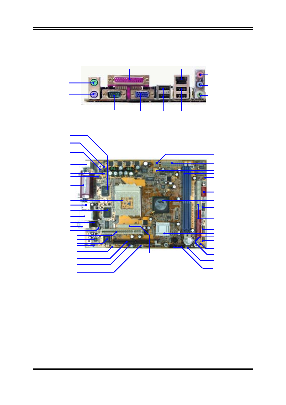
1-4 Layout Diagram & Jumper Setting
PS/2 Mouse
PS/2 Keyboard
ITE IT8705 Chip
K/B Power ON Jumper (JP1)
External Remote Control
PS2 KB/Mouse Port
Serial Port COM2 Connector
RTL8100C LAN Controller
6-Channel Audio Connector
CPU FSB Frequency Jumper
(JP2, JP3)
SFAN1 Connector
PC99 Back Panel
USB Port/LAN Connector
4MBit Flash ROM BIOS
SPDIF-Out Connector
(JP4)
CPU Socket
USB Port
CD In Audio
PCI Slot
AC97’ Codec
SFAN2 Connector
AGP Slot
IR Connector
Wake On LAN
PRINT
6-Channel Speaker
LAN
Center/Base
REAR Speaker
Front Speaker
COM1 USB
VGA USB1
Floppy Connector
ATX 12V Power Conn.
ATX Power Connector
CPUFAN Connecto
DIMM Socket X2
USB Power On Jumper (JP7)
USB Port
VIA KM400A Chip
JW_USB Connecto
ATA 133 IDE Conn.
LCD Display Panel Conn.
VIA VT8237 Chip
IDE LED (JP5)
Reset/Power Switch/
SPDIF-IN Connector
Speaker Connector
Power LED (JP6)
Clear CMOS (JBAT)
Serial-ATA Connector
(SATA1, 2)
Jumpers
5
Jumper Name Description Page
JP1 Keyboard Power On Enable/Disabled
3-pin Block P.8
JP2, JP3 CPU Front Side Bus Frequency 2-pin Block P.7
JBAT CMOS RAM Clear 3-pin Block P.7
JP7 USB Power On Enable/Disabled 3-pin Block P.8
Connectors
Connector Name Description Page
ATXPOW ATX Power Connector 20-pin Block P.12
ATX12V ATX 12V Power Connector 4-pin Block P.13
J1 PS/2 Mouse & PS/2 Keyboard Connector 6-pin Female P.13
UL_B1 USB Port Connector
+ RJ-45 LAN Port Connector
PARALL Parallel Port Connector 25-pin Female P.13
CN1 Line-In/Out, MIC Connector 3 phone jack Connector P.13
COM1 Serial Port COM1 Connector 9-pin Connector P.13
VGA VGA Connector 15-pin Female P.13
FDD Floppy Driver Connector 34-pin Block P.14
IDE1/IDE2 Primary/ Secondary IDE Connector 40-pin Block P.14
SATA1/SATA2 Serial ATA IDE Connector 7-pin Connector P.14
4-pin Connector
+RJ-45 Connector
P.13
Headers
Header Name Description Page
JW_USB Line-Out, MIC Header/
USB2/USB3 Port Headers
USB1 USB Port Headers 9-pin Block P.15
COM2 Serial Port COM2 header 9-pin Block P.16
SPDIF_IN SPDIF-In Port Headers 3-pin Block P.16
SPDIF_OUT SPDIF-Out Port Headers 3-pin Block P.16
JP4 External Remote Control Headers 10-pin Block P.16
JP5 IDE activity LED 2-pin Block P.16
JP6 Power LED 2-pin Block P.16
RESET Reset switch lead 2-pin Block P.17
PWR BTN Power switch 2-pin Block P.17
SPEAK Speaker connector 4-pin Block P.17
JW_LCDFP LCD Display Panel Headers 11-pin Block P.17
WOL Wake On-LAN Headers 3-pin Block P.17
SFAN1,SFAN2,CPUFAN FAN Headers 3-pin Block P.18
IR IR infrared module Headers 5-pin Block P.18
CDIN CD Audio-In Headers 4-pin Block P.18
Expansion Sockets
Socket/Slot Name Description Page
ZIF Socket 462 CPU Socket 462-pin PPGA CPU Socket P.9
DDR1, DDR2 DDR SDRAM Module
Socket
184-pin DDR SDRAM Module
Expansion Socket
PCI1 PCI Slot 32-bit PCI Local Bus Expansion slots P.11
AGP AGP 4X/8X Mode Slot AGP Expansion Slot P.12
13-pin Block P.15
P.10
6
Chapter 2
Hardware installation
2-1 Hardware installation Steps
Before using your computer, you had better complete the following steps:
1. Check motherboard setting
2. Install CPU
3. Install Memory
4. Install Expansion cards
5. Connect Ribbon cables, Panel wires, and power supply
6. Setup BIOS
7. Install software driver & utility
2-2 Checking Motherboard’s Jumper Setting
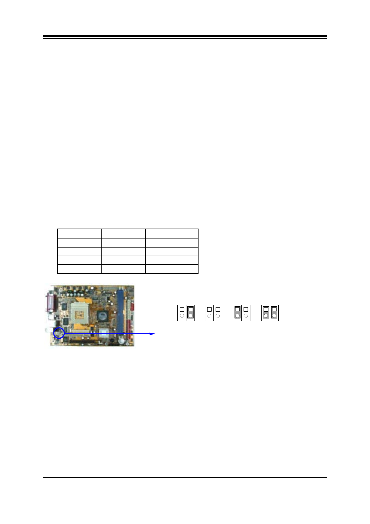
(1) CPU Front Side Bus Frequency Setting (2-pin) : JP2, JP3
JP2 JP3 CPU CLK
OFF ON 100MHz
OFF OFF 133MHz (Default)
ON OFF 166MHz
ON ON 200MHz
JP3
JP2
1
2
133MHz
(Default)
JP2
1
2
100MHz
CPU Front Side Bus Frequency Setting
Note: CPU Front Side Bus Frequency also can setting step by step in BIOS SETUP,
please refer page 35 Miscellaneous Control in Host Clock at Next.
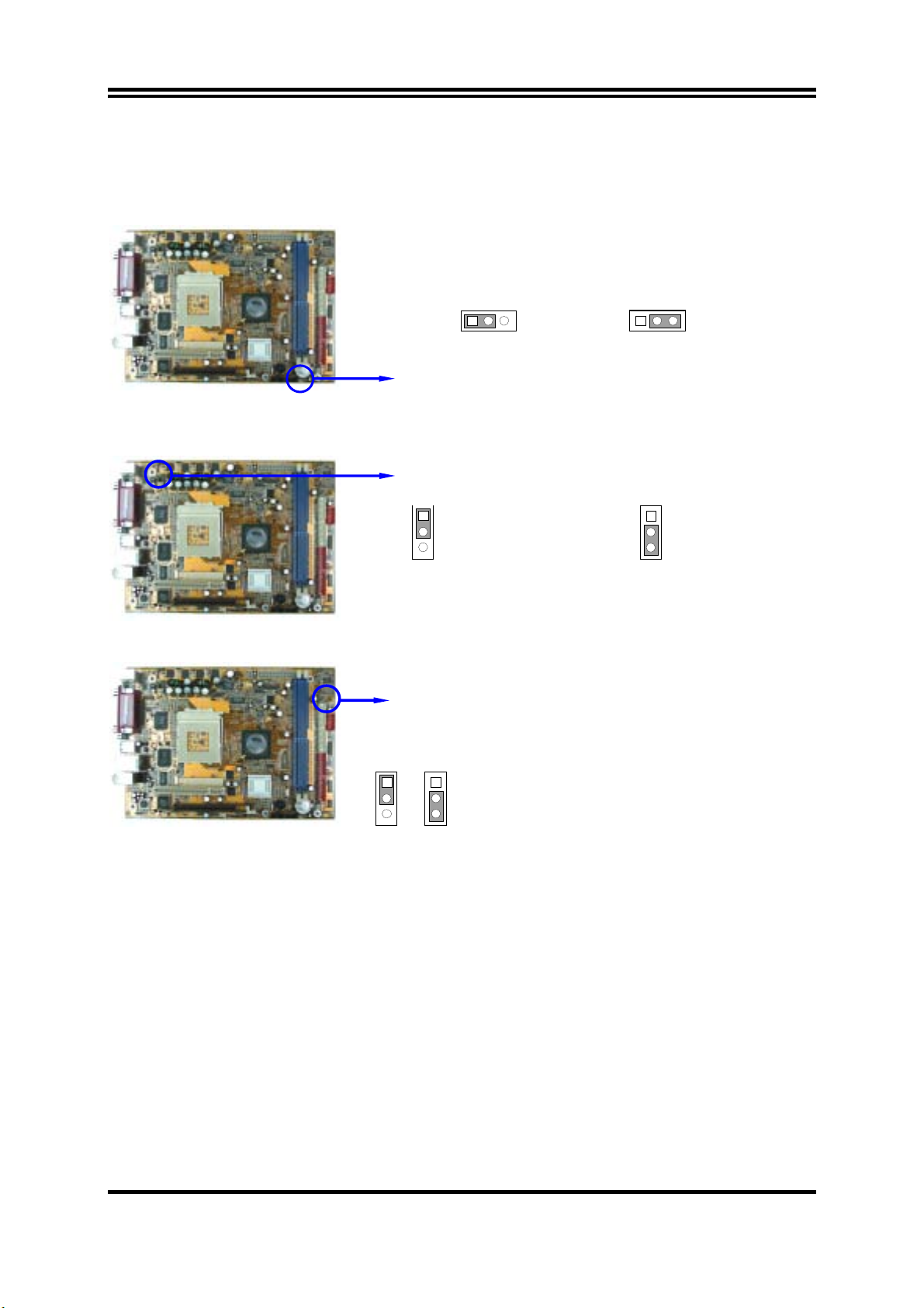
(2) CMOS RAM Clear (3-pin) : JBAT
A battery must be used to retain the motherboard configuration in CMOS RAM short 1-2
pins of JBAT to store the CMOS data.
JP3
JP2
1
2
JP3
166MHz
JP2
JP3
1
2
200MHz
To clear the CMOS, follow the procedure below:
1. Turn off the system and unplug the AC power
2. Remove ATX power cable from ATX power connector
3. Locate JBAT and short pins 2-3 for a few seconds
4. Return JBAT to its normal setting by shorting pins 1-2
5. Connect ATX power cable back to ATX power connector
7
Note: When should clear CMOS
1. Troubleshooting
2. Forget password
3. After over clocking system boot fail
13
JBAT
2-3 closed Clear CMOS
13
JBAT
1-2 closed Normal
CMOS RAM Clear Setting
(3) Keyboard Power On function Enabled/Disabled (3-pin): JP1
When setting Enabled you can using keyboard by key in password to power on system.
JP1
1-2 closed K/B Power ON Disable
(Default)
1
3
Keyboard Power On Setting
JP1
2-3 closed K/B Power ON Enabled
1
3
(4) USB Power On function Enabled/Disabled: JP7
JP7
JP7
JP7 1-2 closed USB Power On Disabled (Default)
1
3
1
JP7 2-3 closed USB Power On Enabled
3
2-3 Install CPU
2-3-1 Glossary
Chipset (or core logic) - two or more integrated circuits which control the interfaces between
the system processor, RAM, I/O devises, and adapter cards.
Processor slot/socket - the slot or socket used to mount the system processor on the
motherboard.
Slot (AGP, PCI, ISA, RAM) - the slots used to mount adapter cards and system RAM.
AGP - Accelerated Graphics Port - a high speed interface for video cards; runs at 1X
(66MHz), 2X (133MHz), or 4X (266MHz).
PCI - Peripheral Component Interconnect - a high speed interface for video cards, sound
cards, network interface cards, and modems; runs at 33MHz.
8

ISA - Industry Standard Architecture - a relatively low speed interface primarily used for
sound cards and modems; runs at approx. 8MHz.
Serial Port - a low speed interface typically used for mouse and external modems.
Parallel Port - a low speed interface typically used for printers.
PS/2 - a low speed interface used for mouse and keyboards.
USB - Universal Serial Bus - a medium speed interface typically used for mouse, keyboards,
scanners, and some digital cameras.
Sound (interface) - the interface between the sound card or integrated sound connectors and
speakers, MIC, game controllers, and MIDI sound devices.
LAN (interface) - Local Area Network - the interface to your local area network.
BIOS (Basic Input/Output System) - the program logic used to boot up a computer and
establish the relationship between the various components.
Driver - software, which defines the characteristics of a device for use by another device or
other software.
Processor - the "central processing unit" (CPU); the principal integrated circuit used for doing
the "computing" in "personal computer"
Front Side Bus Frequency -
the working frequency of the motherboard, which is generated
by the clock generator for CPU, DRAM and PCI BUS.
CPU L2 Cache -
the flash memory inside the CPU, normally Athlon CPU has 256K or above,
while Duron will have 64K.
2-3-2 About AMD Athlon & Duron 462-pin CPU
This motherboard supports Socket-A (Socket-462) AMD Athlon/Duron processors.
This motherboard Provides a ZIF Socket-A. The CPU that comes with the motherboard
should have a cooling FAN attached to prevent overheating. If this is not the case, then
purchase a correct cooling FAN before you turn on your system.
WARNING!
WARNING!
Be sure that there is sufficient air circulation across the processor’s heatsink
and CPU cooling FAN is working correctly, otherwise it may cause the
processor and motherboard overheat and damage, you may install an auxiliary
cooling FAN, if necessary.
Due to this motherboard provides new function of protecting CPU;you must
connect the CPU FAN connector on CPUFAN location in order to obtain this
feature. Without connection on CPUFAN (or you have connect CPU FAN on
FAN1), the system will shut down immediately to protect both your CPU and
motherboard.
To install a CPU, first turn off your system and remove its cover. Locate the ZIF socket and
open it by first pulling the level sideways away from the socket then upward to a 90-degree
angle. Insert the CPU with the correct orientation as shown below. The notched corner
should point toward the end of the level. Because the CPU has a corner pin for two of the
four corners, the CPU will only fit in the orientation as shown.
9
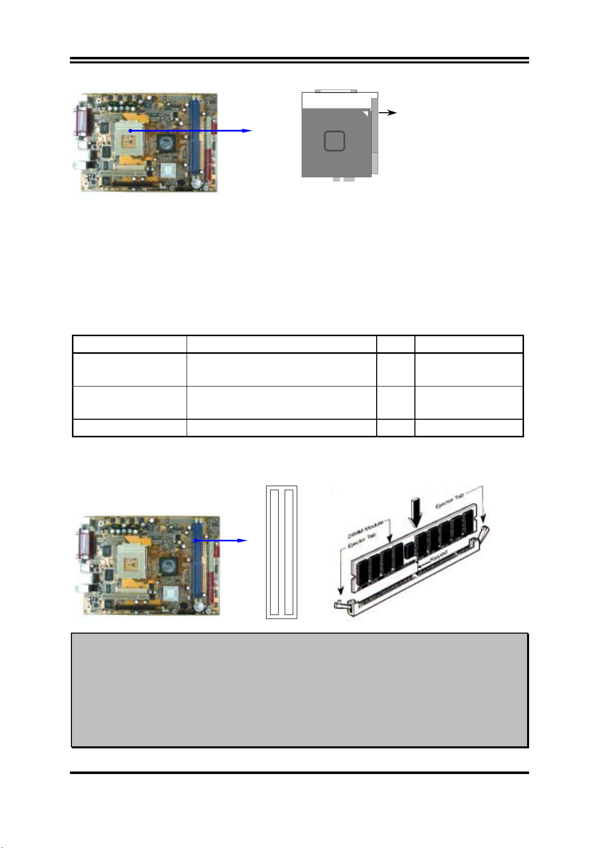
Socket 462
Colden Arrow
CPU ZIF Socket-A
When you put the CPU into the ZIF socket. No force require to insert of the CPU, then press
the level to Locate position slightly without any extra force.
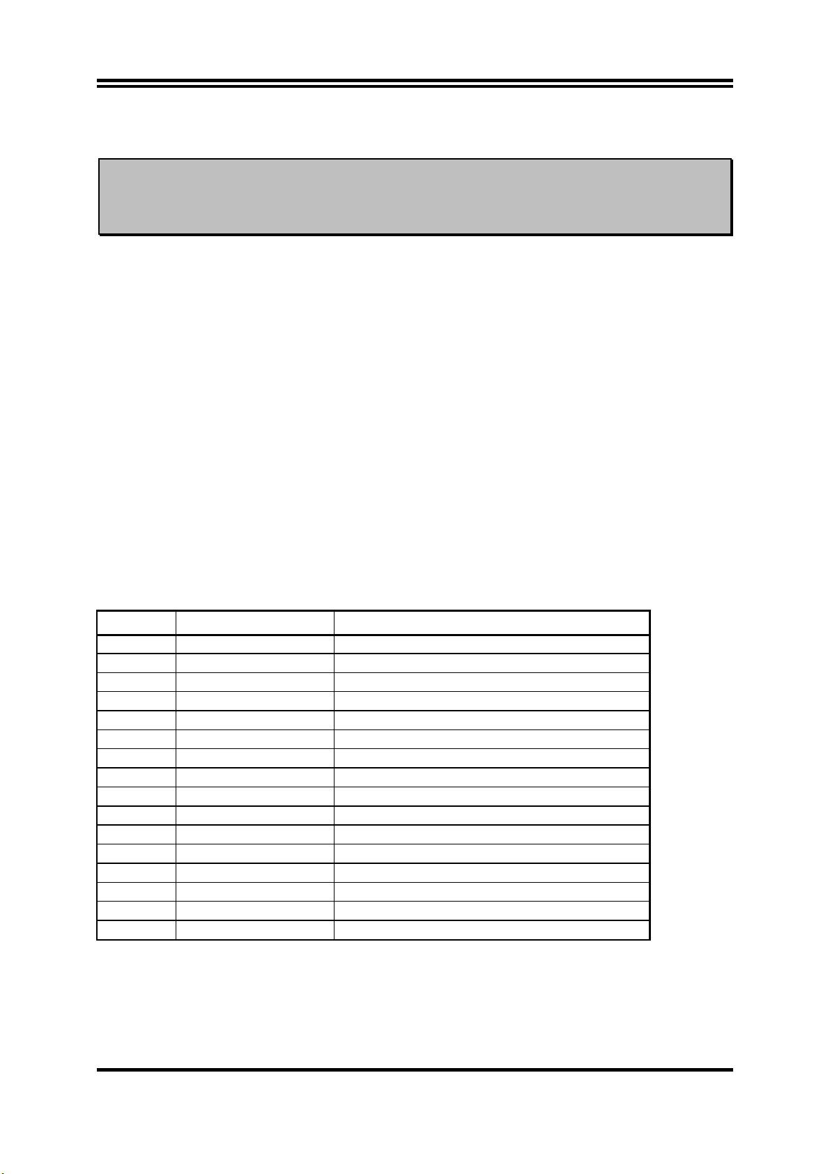
2-4 Install Memory
This motherboard provides two 184-pin DUAL INLINE MEMORY MODULES (DIMM)
sites for memory expansion available from minimum memory size of 64MB to maximum
memory size of 2.0GB DDR SDRAM.
Valid Memory Configurations
Bank 184-Pin DIMM PCS Total Memory
Bank 0, 1 (DDR1) DDR200/DDR266/DDR333/DDR400
DDR SDRAM Module
Bank 2, 3 (DDR2) DDR200/DDR266/DDR333/DDR400
DDR SDRAM Module
Total System Memory (Max. 2.0GB) 2 64MB∼2.0GB
X1 64MB∼1.0GB
X1 64MB∼1.0GB
Generally, installing DDR SDRAM modules to your motherboard is very easy, you can refer to
figure 2-4 to see what a 184-Pin DDR200/DDR266/DDR333/DDR400 DDR SDRAM module looks
like.
DDR2 (BANK2 + BANK3)
DDR1 (BANK0 + BANK1)
Figure 2-4
NOTE!
When you install DIMM module fully into the DIMM socket the eject tab should
be locked into the DIMM module very firmly and fit into its indention on both
sides.
WARNING!
For the DDR SDRAM CLOCK is set at 133MHz, use only DDR266-compliant
DDR Modules. When this motherboard operate at 133Mhz, most system will not
even boot if non-compliant modules are used because of the strict timing issues, if
your DDR Modules are not DDR266-compliant, set the DDR SDRAM clock to
100MHz to ensure system stability.
10
2-5 Expansion Cards
WARNING!
Turn off your power when adding or removing expansion cards or other
system components. Failure to do so may cause severe damage to both
your motherboard and expansion cards.
2-5-1 Procedure For Expansion Card Installation
1. Read the documentation for your expansion card and make any necessary hardware or
software setting for your expansion card such as jumpers.
2. Remove your computer’s cover and the bracket plate on the slot you intend to use.
3. Align the card’s connectors and press firmly.
4. Secure the card on the slot with the screen you remove above.
5. Replace the computer system’s cover.
6. Set up the BIOS if necessary.
7. Install the necessary software driver for your expansion card.
2-5-2 Assigning IRQs For Expansion Card
Some expansion cards need an IRQ to operate. Generally, an IRQ must exclusively assign to
one use. In a standard design, there are 16 IRQs available but most of them are already in use.
Standard Interrupt Assignments
IRQ Priority Standard function
0 N/A System Timer
1 N/A Keyboard Controller
2 N/A Programmable Interrupt
3 * 8 Communications Port (COM2)
4 * 9 Communications Port (COM1)
5 * 6 Sound Card (sometimes LPT2)
6 * 11 Floppy Disk Controller
7 * 7 Printer Port (LPT1)
8 N/A System CMOS/Real Time Clock
9 * 10 ACPI Mode when enabled
10 * 3 IRQ Holder for PCI Steering
11 * 2 IRQ Holder for PCI Steering
12 * 4 PS/2 Compatible Mouse Port
13 N/A Numeric Data Processor
14 * 5 Primary IDE Channel
15 * 1 Secondary IDE Channel
* These IRQs are usually available for ISA or PCI devices.
11
2-5-3 Interrupt Request Table For This Motherboard
Interrupt request are shared as shown the table below:
INT A INT B INT C INT D
PCI slot 1 Shared
AGP slot Shared
AC97/MC97
Onboard USB
Onboard USB 1
Shared
Shared
Shared
IMPORTANT! If using PCI cards on shared slots, make sure that the drivers support
“Shared IRQ” or that the cards don’t need IRQ assignments. Conflicts will
arise between the two PCI groups that will make the system unstable or
cards inoperable.
2-5-4 AGP Slot
This motherboard provides an AGP Slot, support the 2X/4X/8X AGP VGA card.
AGP SLOT
2-6 Connectors, Headers
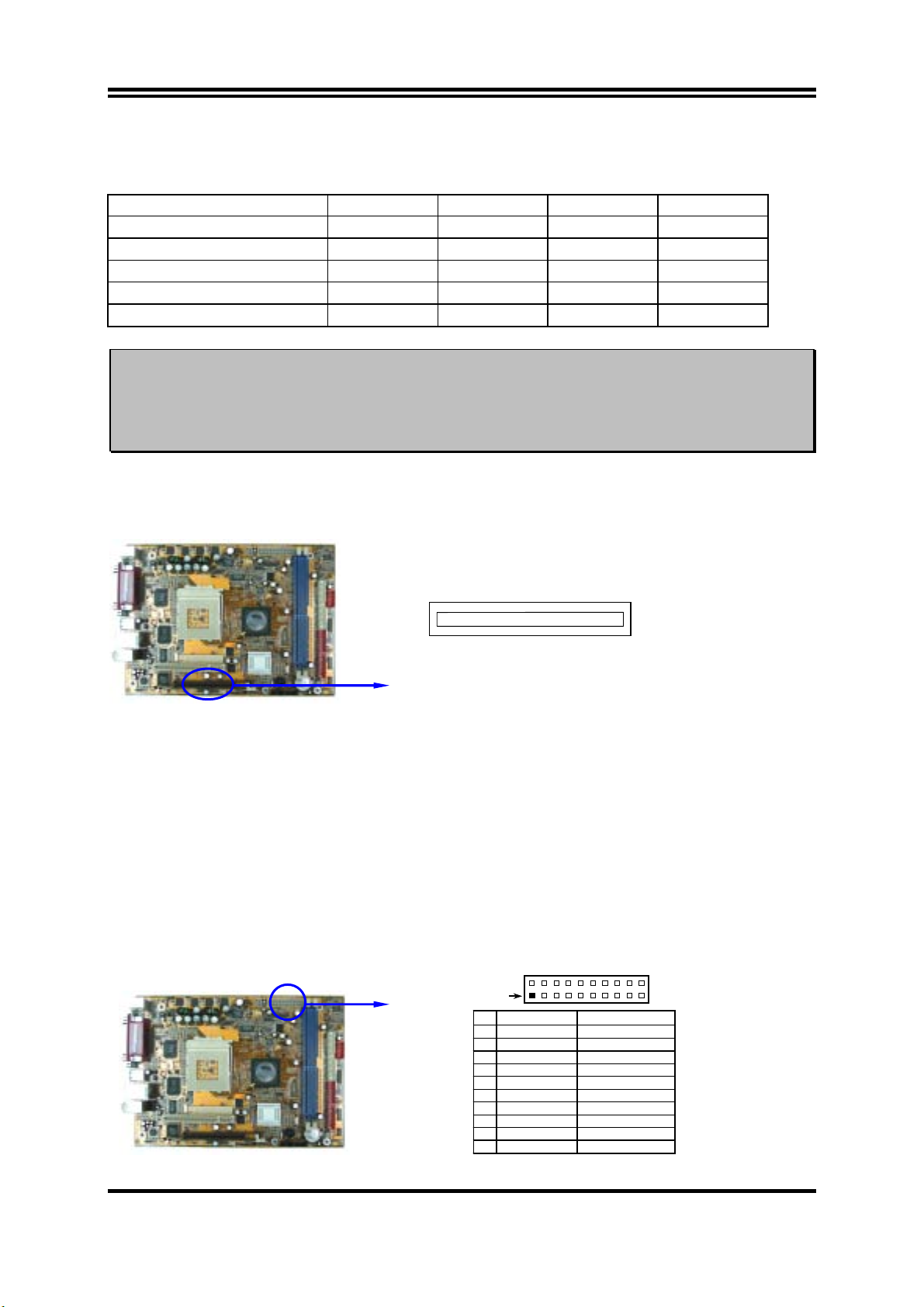
2-6-1 Connectors
(1) Power Connector (20-pin block) : ATXPOW
ATX Power Supply connector. This is a new defined 20-pins connector that usually
comes with ATX case. The ATX Power Supply allows to use soft power on momentary
switch that connect from the front panel switch to 2-pins Power On jumper pole on the
motherboard. When the power switch on the back of the ATX power supply turned on,
the full power will not come into the system board until the front panel switch is
momentarily pressed. Press this switch again will turn off the power to the system
board.
1 3.3V 3.3V
2 -12V 3.3V
3 GND GND
4 Soft Power On 5V
5 GND GND
6 GND 5V
7 GND GND
8 -5V Power OK
9 +5V +5V (for Soft Logic)
10 +5V +12V
Pin 1
PIN ROW2 ROW1
12
(2) ATX 12V Power Connector (4-pin block) : ATX12V
This is a new defined 4-pins connector that usually comes with ATX Power Supply. The
ATX Power Supply which fully support Pentium 4 processor must including this
connector for support extra 12V voltage to maintain system power consumption.
Without this connector might cause system unstable because the power supply can not
provide sufficient current for system.
Pin 1
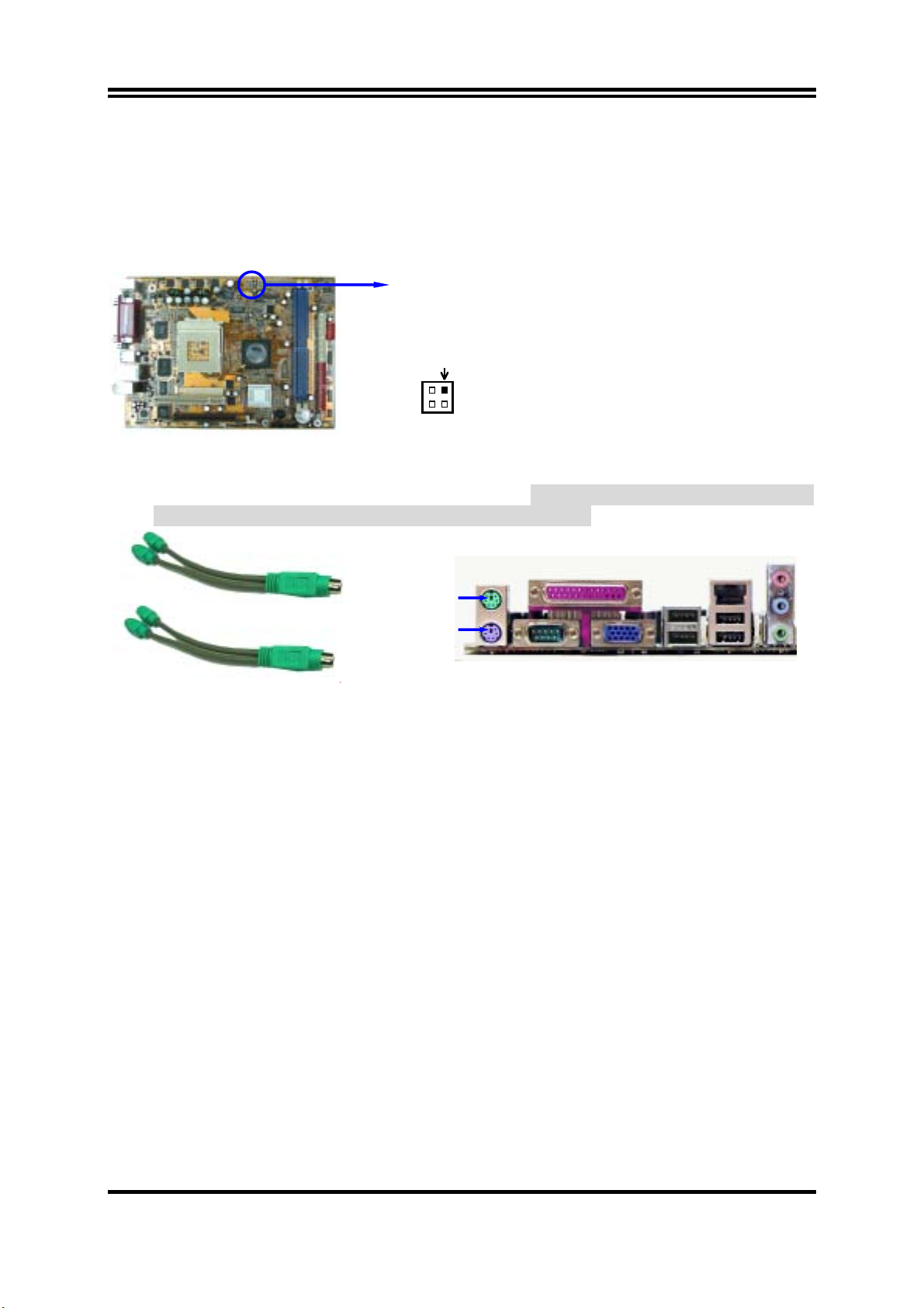
PS/2 Mouse & PS/2 Keyboard Connector : J1
(3)
The connectors for PS/2 keyboard and PS/2 Mouse.
It can connect with a Y-Cable which
can support 2 Keyboard and 2 Mouse for 2 user function.
Mouse Y-Cable
Keyboard Y-Cable
(4) USB Port connector: USB
The connectors are 4-pin connector that connect USB devices to the system board.
(5) LAN Port connector: UL_B1
This connector is standard RJ45 connector for Network.
(6) Parallel Port Connector (25-pin female): PARALL
Parallel Port connector is a 25-pin D-Subminiature Receptacle connector. The On-board
Parallel Port can be disabled through the BIOS SETUP. Please refer to Chapter 3
“INTEGRATED PERIPHERALS SETUP” section for more detail information.
(7) Audio Connector : CN1
This Connector are 3 phone Jack for LINE-OUT, LINE-IN, MIC function port.
Line-out :
Line-in :
Audio input to sound chip (Rear-Speaker in 6-channel function)
MIC :
Audio output to speaker (Front-Speaker in 6-channel function)
Microphone Connector (Center/Base Speaker in 6-channel function)
(8) Serial Port COM1 : COM1
COM1, COM2 are the 9-pin D-Subminiature mail connector. The On-board serial port can
be disabled through BIOS SETUP. Please refer to Chapter 3 “INTEGRATED
PERIPHERALS SETUP” section for more detail information.
(9) VGA Connector (15-pin D-Sub) Connector: VGA
VGA is the 15-pin D-Subminiature female connector for display monitor.
13
 Loading...