

Page 1

S755TWIN
USER'S MANUAL
M/B For Socket 754 AMD Athlon64
Processor
NO. G03-S755T8
Rev:1.0
Release date: April 2003
Trademark:
* Specifications and Information contained in this documentation are furnished for information use only, and are
subject to change at any time without notice, and should not be construed as a commitment by manufacturer.
Page 2

USER’S NOTICE ................................................................................................................ ii
MANUAL REVISION INFORMATION ................................................................................ ii
COOLING SOLUTIONS...................................................................................................... ii
CHAPTER 1 INTRODUCTION OF S755TWIN MOTHERBOARD
1-1 FEATURE OF MOTHERBOARD ......................................................................... 1
1-2 SPECIFICATION................................................................................................... 2
1-3 PERFORMANCE LIST ......................................................................................... 3
1-4 LAYOUT DIAGRAM & JUMPER SETTING ......................................................... 4
CHAPTER 2 HARDWARE INSTALLATION
2-1 HARDWARE INSTALLATION STEPS................................................................. 6
2-2 CHECKING MOTHERBOARD'S JUMPER SETTING ........................................ 6
2-3 INSTALL CPU ....................................................................................................... 7
2-3-1 GLOSSARY ............................................................................................... 7
2-3-2 ABOUT INTEL AMD K8 754-PIN CPU..................................................... 8
2-4 INSTALL MEMORY .............................................................................................. 8
2-5 EXPANSION CARD .............................................................................................. 9
2-5-1 PROCEDURE FOR EXPANSION CARD INSTALLATION...................... 9
2-5-2 ASSIGNING IRQ FOR EXPANSION CARD............................................. 9
2-5-3 INTERRUPT REQUEST TABLE FOR THIS MOTHERBOARD.............. 10
2-5-4 AGP SLOT ................................................................................................. 10
2-6 CONNECTORS, HEADERS ................................................................................. 11
2-6-1 CONNECTORS ......................................................................................... 11
2-6-2 HEADERS.................................................................................................. 14
2-7 STARTING UP YOUR COMPUTER..................................................................... 18
CHAPTER 3 INTRODUCING BIOS
3-1 ENTERING SETUP............................................................................................... 19
3-2 GETTING HELP .................................................................................................... 19
3-3 THE MAIN MENU.................................................................................................. 20
3-4 STANDARD CMOS FEATURES.......................................................................... 21
3-5 ADVANCED BIOS FEATURES ............................................................................ 22
3-6 ADVANCED CHIPSET FEATURES..................................................................... 24
3-6-1 DRAM TIMING SETTINGS ....................................................................... 25
3-7 INTEGRATED PERIPHERALS ............................................................................ 26
3-7-1 ONBOARD IDE FUNCTION ..................................................................... 26
3-7-2 ONBOARD DEVICE FUNCTION.............................................................. 27
3-7-3 ONBOARD SUPER IO FUNCTION.......................................................... 28
3-8 POWER MANAGEMENT SETUP ........................................................................ 29
3-8-1 PM TIMER RELOAD EVENTS ................................................................ 30
3-9 PNP/PCI CONFIGURATION SETUP ................................................................... 30
3-9-1 IRQ RESOURCES.................................................................................... 31
3-10 PC HEALTH STATUS ......................................................................................... 32
3-11 MISCELLANEOUS CONTROL ........................................................................... 32
3-12 LOAD STANDARD/OPTIMIZED DEFAULTS..................................................... 33
3-13 SET SUPERVISOR/USER PASSWORD............................................................ 34
CHAPTER 4 DRIVER & FREE PROGRAM INSTALLATION
MAGIC INSTALL SUPPORTS WINDOWS 98SE/ME/NT4.0/2000/XP ........................ 35
4-1 AGPVXD
4-2 IDE
4-3 SOUND
4-4 LAN
4-5 PC-HEALTH
MONITORING DEVICE
4-6 PC-CILLIN
4-7 USB2.0
4-8 RAID
4-9 HOW TO DISABLE ON-BOARD SOUND ................................................................. 43
4-10 HOW TO UPDATE BIOS.............................................................................................. 43
TABLE OF CONTENT
INSTALL SIS AGPVXD DRIVER .................................................... 36
INSTALL SIS MINI IDE DRIVER..................................................... 37
INSTALL ALC AUDIO CODEC DRIVER........................................ 37
INSTALL LAN CONTROLLER DRIVER ........................................ 38
INSTALLS SMART GUARDIAN SOFTWARE FOR HARDWARE
..............................................................
INSTALL PC-CILLIN2002 ANTI-VIRUS PROGRAM .................... 40
INSTALL SIS USB2.0 DEVICE DRIVER........................................ 41
INSTALL SIS 180 RAID DRIVER AND UTILITY ........................... 42
39
i
Page 3

USER’S NOTICE
COPYRIGHT OF THIS MANUAL BELONGS TO THE MANUFACTURER. NO PART OF THIS MANUAL,
INCLUDING THE PRODUCTS AND SOFTWARE DESCRIBED IN IT MAY BE REPRODUCED,
TRANSMITTED OR TRANSLATED INTO ANY LANGUAGE IN ANY FORM OR BY ANY MEANS WITHOUT
WRITTEN PERMISSION OF THE MANUFACTURER.
THIS MANUAL CONTAINS ALL INFORMATION REQUIRED TO USE S755TWIN MOTHER-BOARD AND WE
DO ASSURE THIS MANUAL MEETS US ER’S REQ UIREMENT BUT WILL CHANGE, CORRECT ANY TIME
WITHOUT NOTICE. MANUFACTURER PROVIDES THIS MANUAL “AS IS” WITHOUT WARRANTY OF ANY
KIND, AND WILL NOT BE LIABLE FOR ANY INDIRECT, SPECIAL, INCIDENTIAL OR CONSEQUENTIAL
DAMAGES (INCLUDING DAMANGES FOR LOSS OF PROFIT, LOSS OF BUSINESS, LOSS OF USE OF DATA,
INTERRUPTION OF BUSINESS AND THE LIKE).
PRODUCTS AND CORPORATE NAMES APPEARING IN THIS MANUAL MAY OR MAY NOT BE
REGISTERED TRADEMARKS OR COPYRIGHTS OF THEIR RESPECTIVE COMPANIES, AND THEY ARE
USED ONLY FOR IDENTIFICATION OR EXPLANATION AND TO THE OWNER’S BENEFIT, WITHOUT
INTENT TO INFRINGE.
Manual Revision Information
Reversion Revision History Date
1.0 First Release April 2003
Item Checklist
5
S755TWIN Motherboard
5
Cable for IDE/Floppy
5
CD for motherboard utilities
□
Cable for USB Port 3/4 (Option)
5
Cable for Serial ATA IDE Port
5
SPDIF-IN/SPDIF-OUT Adaptor
5
S755TWIN User’s Manual
AMD K8 Processor Family
Cooling Solutions
As processor technology pushes to faster speeds and higher performance with increasing operation
clock, thermal management becomes increasingly crucial while building computer systems. Maintaining
the proper computing environment without thermal increasing is the key to reliable, stable, and 24
hours system operation. The overall goal is keeping the processor below its specified maximum case
temperature. Heatsinks induce improved processor heat dissipation through increasing surface area
and concentrated airflow from attached active cooling fans. In addition, interface materials allow
effective transfers of heat from the processor to the heatsink. For optimum heat transfer, AMD
recommends the use of thermal grease and mounting clips to attach the heatsink to the processor.
Please refer to the website below for collection of heatsinks evaluated and recommended for Socket-A
processors by AMD. In addition, this collection is not intended to be a comprehensive listing of all
heatsinks that support Socket-754 processors.
For vendor list of heatsinks and Active cooling fans, please visit:
http://www.amd.com/us-en/Processors/DevelopWithAMD/0,,30_2252_869_9460^9515,00.html
ii
Page 4
Introduction
MagicTwin is a 2-User-System solution built on this special designed motherboard with a dual headed AGP
graphic card, two PS/2 keyboard and mouse Y-cables and one piece of software (Driver and Tools). It allows you
to add one additional station simultaneously running Windows XP Home or XP-Professional (Service Pack 1).
System Requirement
Jetway MagicTwin Motherboard:
2 x PS/2 Y-cable
Install CD (Driver and MagicTwin)
Serial Number and Activation Key
Purchased Separately from Dealer:
>=1.2 GHz Processor
Min 256MB DRAM
NVIDIA Dual Head AGP Graphic Card
Windows XP Home, Prof. w/ SP1
2 x PS/2 Keyboards
2 x PS/2 Mice
2 x Monitors
Necessary Components to Configure 2-User-System
¾ one special designed Motherboard with connectivity hardware onboard
¾ one dual head AGP graphic card (purchased separately from your dealer)
¾ two Y-cables for two PS/2 Keyboards and two PS/2 Mice
¾ MAGIC INSTALL CD (incl. all DRIVERS you need and some TOOLS to enable the 2-User function of
the motherboard). In addition this CD includes an auto detect software, which detects, installs and
assigns the related 2
¾ one serial number and activation key (printed on the sticker label on top of the CD package folding seal)
¾ two monitors
¾ two speaker systems (optional)
Recommendations
¾ CPU: >1GHz
¾ minimum 256 MB RAM for two Stations, running simultaneously
¾ two Standard PS/2 Keyboards, -Mice and two Monitors (Sound: optional)
¾ Hard disk and CD-ROM drive
Installation of MagicTwin
¾ We recommend to install Windows XP and all related drivers from the scratch
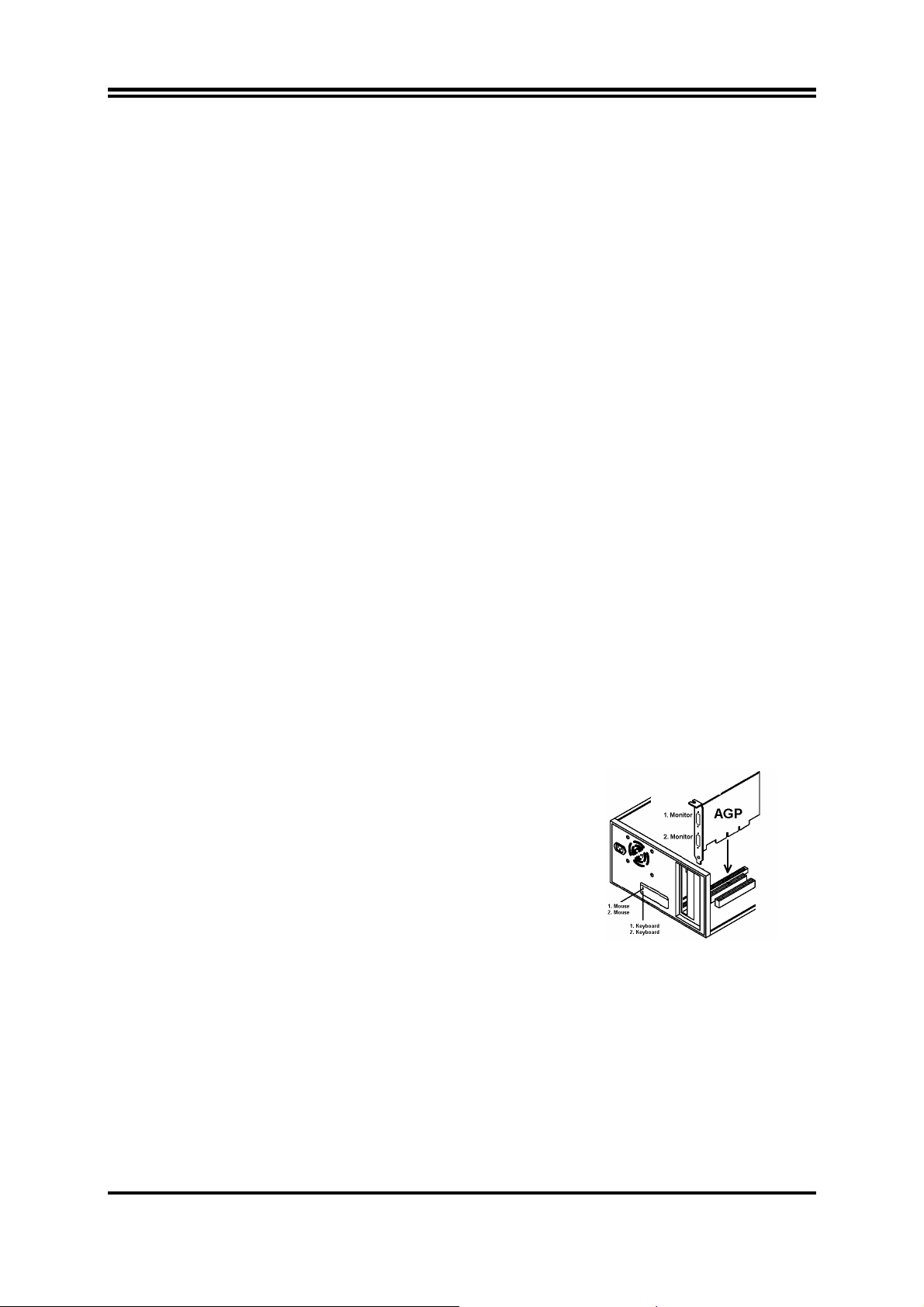
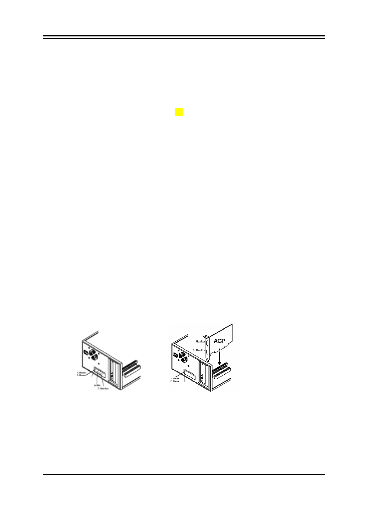
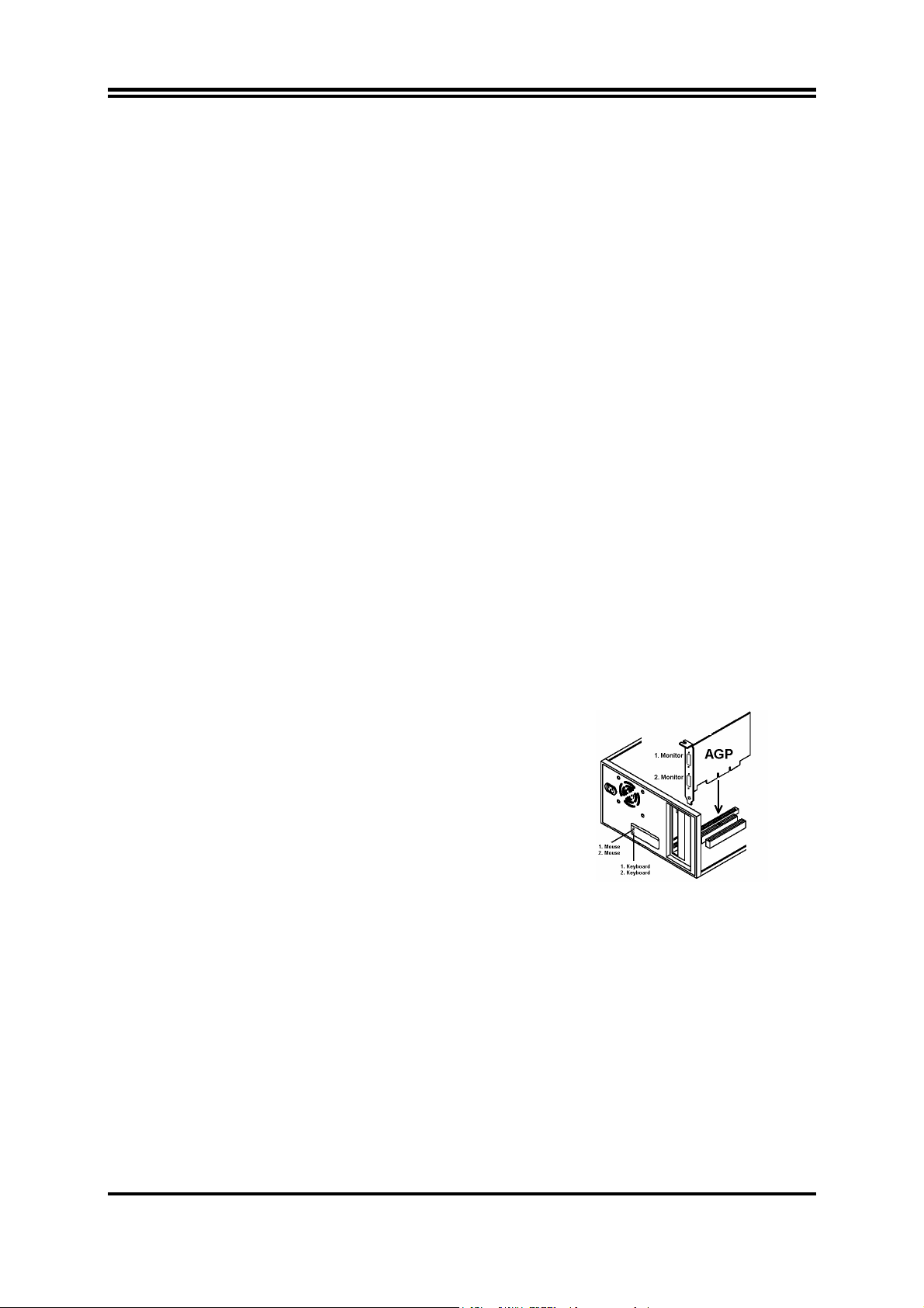
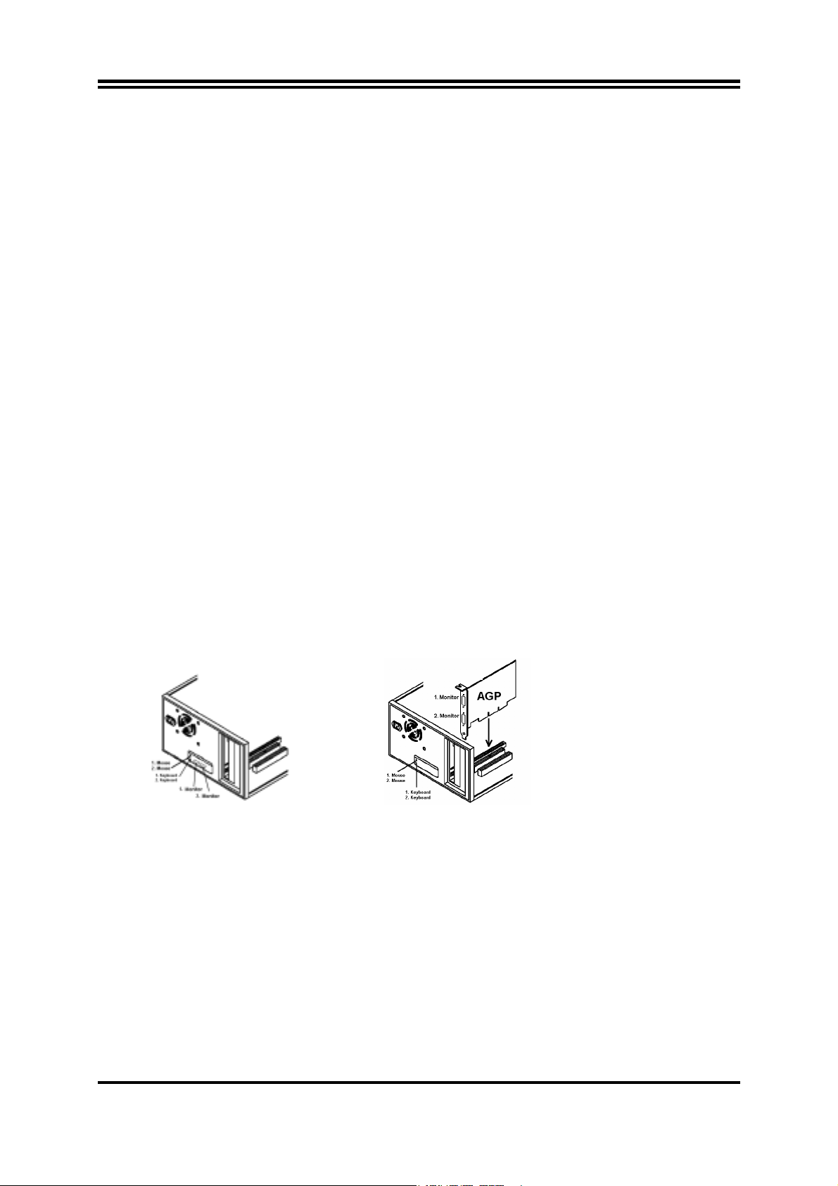
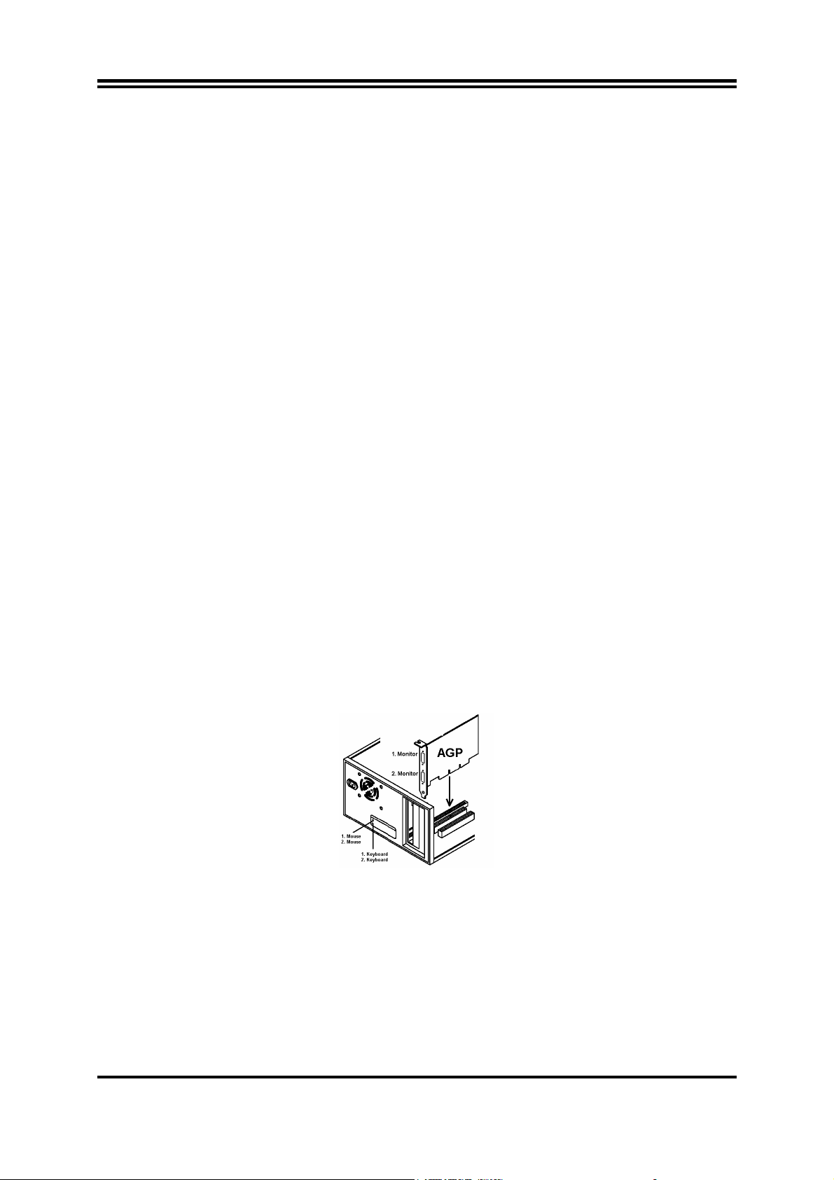
¾ Switch off your PC and open the computer case
¾ Remove the AGP slot bracket and insert a dual headed AGP
Video Card purchased separately from your dealer into the AGPslot. If the delivered motherboard comes with dual VGA port
onboard, please skip this step.
nd
video display and the 2nd PS/2 keyboard and PS/2 mouse.
Dual Port AGP VGA Card
¾ As well attach the delivered Y-cables to the “green” port (former PS/2 Mouse port) and into the “violet”
port (former PS/2 Keyboard port) at the rear side of the motherboard.
¾ Connect the 1
st
the 1
and 2nd keyboard to the other Y-cable, which is also connected to the “violet” port. The additional
monitor MUST be attached otherwise windows will not detect and enable the 2
st
and 2nd mouse to the Y-cable, which is also linked to the “green” PS/2 connector and
nd
monitor. Make sure the
additional keyboards and mice work; they should affect the host console.
¾ Start your PC. Windows will automatically detect the new AGP Video device as a standard VGA-card.
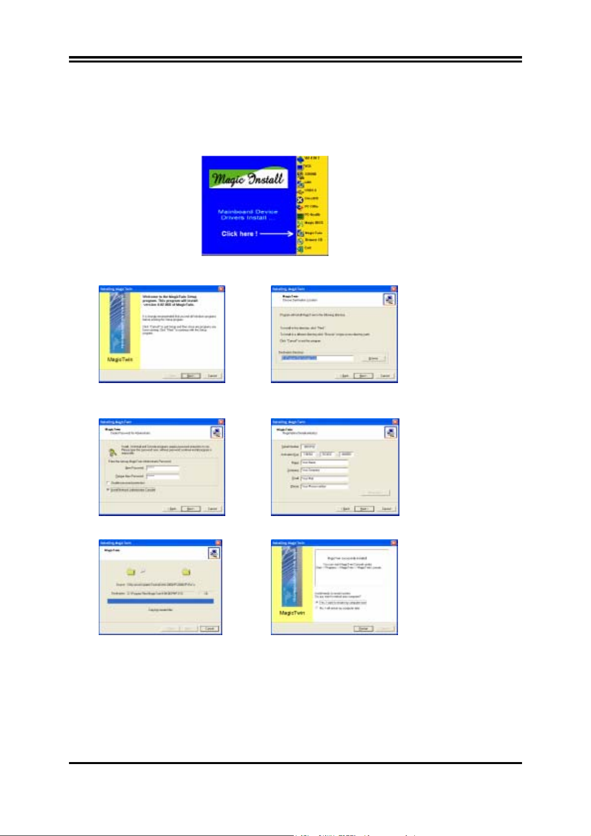
Please install first all drivers before installing “MagicTwin” of the MAGIC INSTALL CD. Insert the CD,
wait for the automatic start and run the Installation of all other drivers beside the MagicTwin from the
Magic Install CD. If the CD does not run automatically, please click to Start-> Run-> CD-Drive->
SETUP.EXE.
m1
Page 5
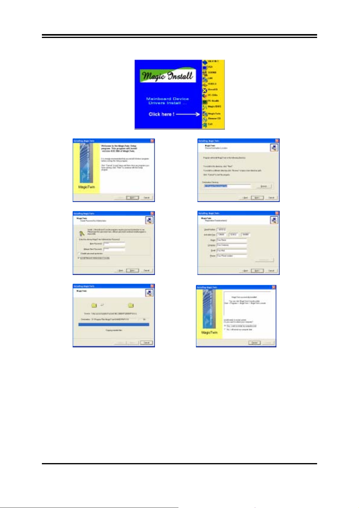
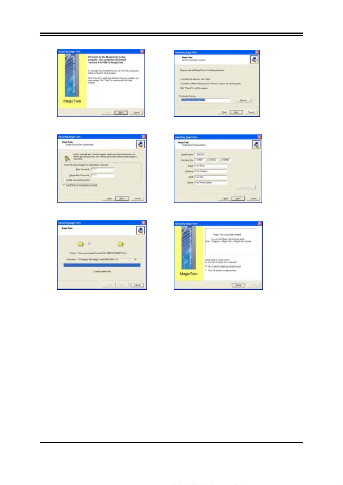
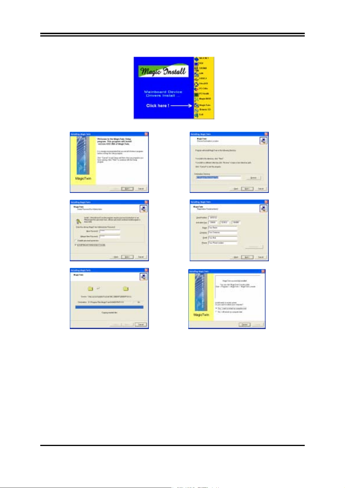
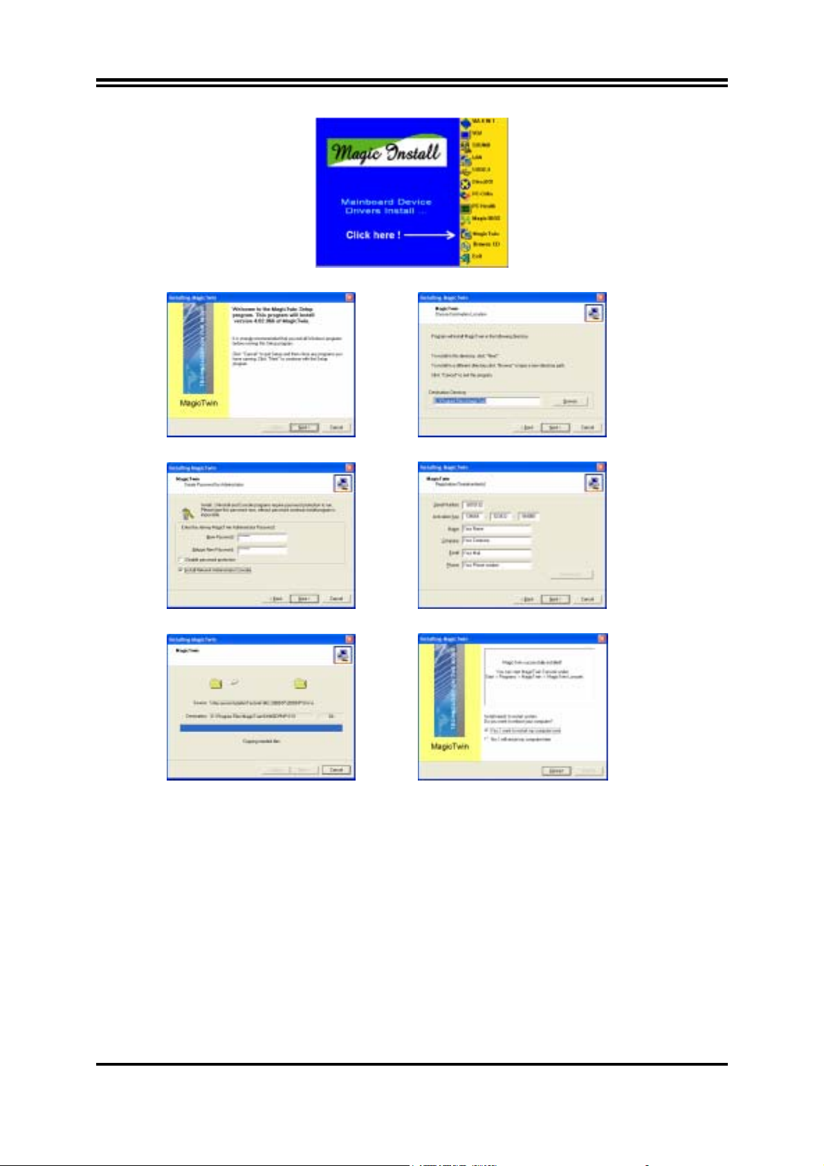
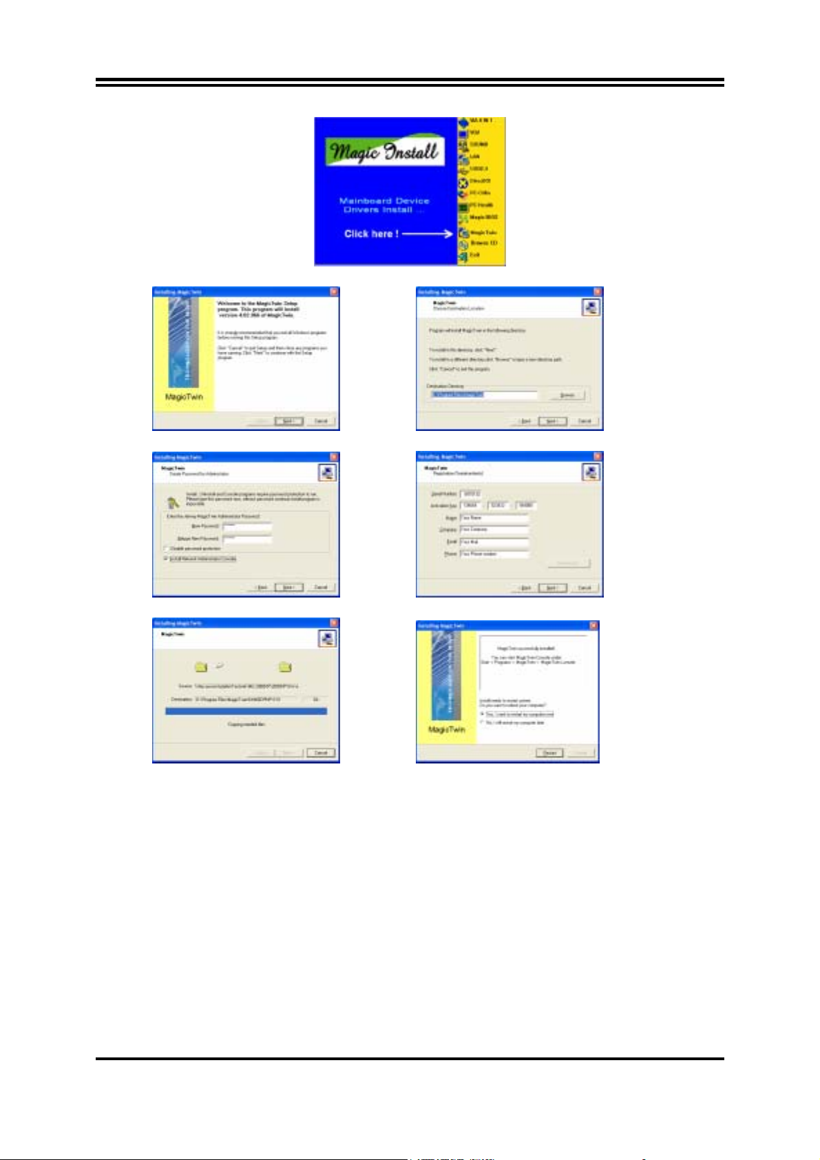
¾ After all other drivers have been installed, lastly install the MagicTwin as follow:
Click “MagicTwin” when the MAGIC INSTALL MENU appears. The Installation-routine will start…
Welcome- Mask, click “Next” Option: Change destination path or click “Next”
Password and Network Console, click “Next” Type in the Serial and Address, click “Next”
Installation in process, please wait… Afterwards “Reboot your PC”.
¾ Windows is restarting and loading the new installed drivers. The MagicTwin will be activated and assign
automatically the 2
¾ Please login in to Windows and add one or more additional users under the control panel.
nd
Station to the 2nd monitor, -PS/2-keyboard and PS/2 mouse.
Dual Head AGP-card
The NVIDIA MX 440-8X, MX-4000, FX 5200 and FX5600 dual-head graphic cards are supported under
MagicTwin. One display can be used by the host and the second by the MagicTwin station. Contact your dealer
for purchasing of the validated NVIDIA dual head AGP VGA card. Among them are:
1. Jetway NV18-A2-64B 2. Jetway NV34-AD-128B 3. Jetway N31X-AD-128B
4. Asustek V9520 5. Leadtek A340 6. Leadtek A180
7. MSI FX5600-TD128 8. MSI FX5200-TD128
m2
Page 6
Einführung
Dieses Barebone-System ist eine Multi-User-Plattform, welche die Verbindung zweier Benutzer zum System
ermöglicht. Mit einer Anschlusshardware onboard und einer innovativen Software, erlaubt das MagicTwin
Barebone System zwei Benutzern verbunden zu sein und simultan eine Windows – Session zu betreiben. Jeder
der zwei Benutzer hat dabei das Gefühl, seinen eigenen Windows-XP Rechner zu haben. Jeder Benutzer
benötigt seine eigene Tastatur, seine eigene Maus, Soundkarte und seinen eigenen Monitor. Die übrige PC
Hardware wird geteilt, sogar die IP. Alles was Sie brauchen ist ein einzelnes MiniQ MagicTwin System mit
minimal einem 1.0 GHz oder einem höherem Prozessor, 256M RAM - Speicher (128MB pro Arbeitsstation/
Benutzer) und einem zweifachen VGA-Port. Sie können sofort dem einzelnen PC eine zusätzliche
Benutzerstation hinzufügen und aus eins zwei machen!
Systemvorraussetzungen bzw. Empfehlungen
MiniQ MagicTwin Series Barebone System
2 x Oktopus- Kabel for PS/2 keyboard and PS/2 mouse
1 x MagicTwin Installation CD (driver and digital description)
1 x Serien- Nummer mit Authorisationscodes und Linzenzvereinbarung
Purchased Parts
>= 1.2GHz Prozessor
256MB Systemspeicher
Windows XP Home oder Professional, sowie das installierte Service Pack 1
Dual- Head- VGA- AGP Grafikkarte von Ihrem Händler beziehen
2 x PS/2 Tastatur (Kabel oder Kabellos)
2 x PS/2 Maus (Kabel oder Kabellos)
2 x SVGA Standard Monitor (CRT Monitor oder TFT Flachbildschirm)
Installation der MagicTwin
Wir weisen ausdrücklich darauf hin, das Ihr Gerät alle Systemvorraussetzungen für die MagicTwin Technologie
gegeben sind. Jedes MagicTwin System benoetigt zwei VGA- Ports. Sie können eine Dual- Head- VGA- AGP
Grafikkarte von Ihrem Händler beziehen. Bereiten Sie die Installation vor, in dem Sie sicherstellen, das Sie in
Ihrem Barebone- Pcs Prepare eine der folgenden Komponenten benutzen: a). hinzugefügt Dual Head AGP VGA
Karte (2 VGA Ports) b). Dual Port VGA- Grafik onboard
Überprüfen Sie das Mainboard und die Barebone- Verpackung und folgen Sie der Installation für die
Bereitstellung des 2. VGA- Ports.
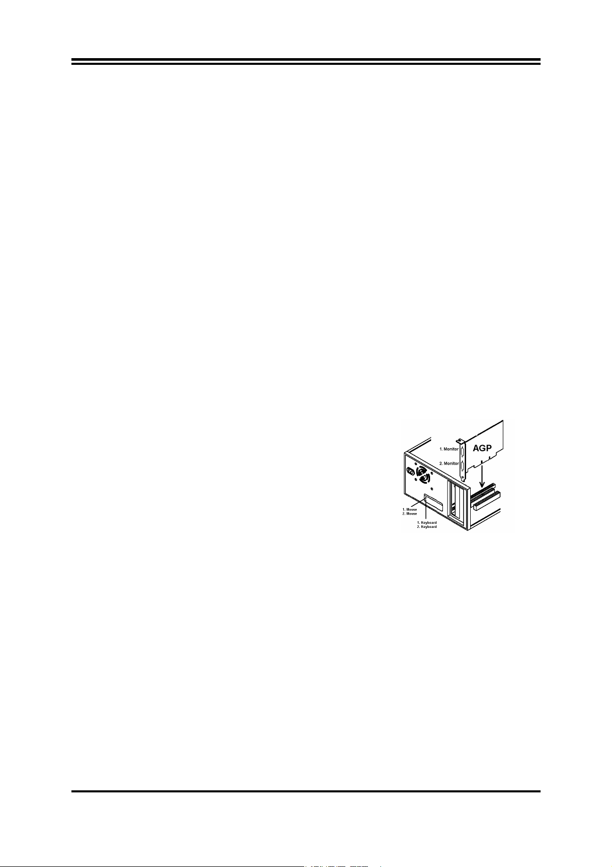
Schalten Sie Ihren PC aus und öffnen Sie das Gehäuse. Entfernen Sie das Slotblech für den VGA- Port und
setzen Sie an dieser Stelle eine Dual Head AGP Grafikkarte, welche Sie separat erworben haben, in den AGPSlot. Wenn Ihr geliefertes Mainboard mit zwei VGA- Ports onboard geliefert wurde, überspringen Sie bitte diesen
Schritt.
®
Series
Onboard Dual Port VGA Dual Port AGP VGA Card
Nun schliessen Sie die zwei mitgelieferten Oktopus Kabel auf der Rückseite des Mainboards an, eines an den
“gruenen” Port (normalerweise PS/2 Maus Port) und den Anderen an den “violetten” Port (normalerweise PS/2
Tastatur Port). Verbinden Sie nun die erste und zweite Maus mit dem Oktopus Kabel, welches bereits mit dem
“gruenen” PS/2 Anschluss, und die erste und zweite Tastatur, welches bereits mit dem “violetten” Port verbunden
ist. Der zusätzliche Monitor muss angeschlossen sein, da Windows den 2. Monitor sonst nicht erkennt und
aktiviert. Starten Sie nun Ihren Computer neu.
m3
Page 7
Software Installation
Starten Sie Ihren Computer neu. Windows erkennst automatisch die neue AGP Grafikkarte als eine standard
VGA- Garfikkarte. Bitte installieren Sie zunächst alle anderen aktuellen Treiber und erst danach den Treiber
“MagicTwin” der MAGIC INSTALL CD. Legen Sie die CD ein, und warten auf den automatischen Start und
starten die Installation der MagicTwin- Software von der Magic Install CD. Falls die CD nicht automatisch startet,
klicken Sie bitte auf Start-> Ausführen-> CD-Laufwerk-> SETUP.EXE.
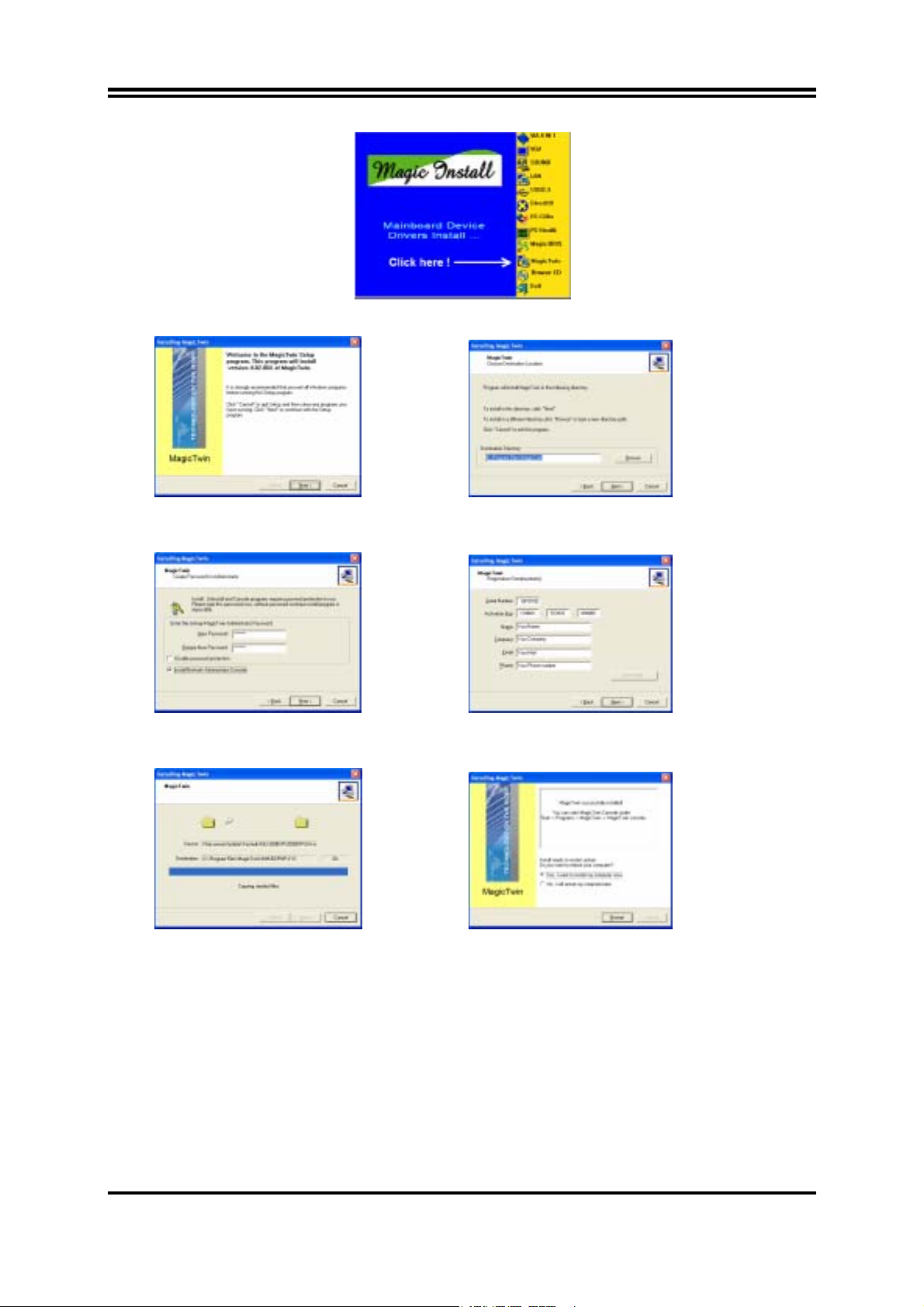
Klicken Sie auf “MagicTwin” wenn das MAGIC INSTALL MENUE erscheint. The Installationsroutine startet
Willkommensbildschirm, klicken Sie auf “Next” Option: Ändern Sie den Zielpfad oder klicken auf “Next”
Passwort und Netzwerk- Konsole, klicken Sie “Next” Geben Sie Seriennummer und Adresse ein, auf “Next”
Die Installation wird ausgeführt, bitte warten… Danach “Starten Sie Ihren Computer neu”.
Windows startet neu und lädt die neu installierten Treiber. MagicTwin ist nun aktiv und weist automatisch die 2.
Arbeitsstation dem zweiten Monitor , -PS/2-Tastatur und PS/2 Maus zu.
Bitte loggen Sie sich nun bei Windows ein, und fügen Sie ein oder mehrere Benutzerkonten in der
Systemsteuerung hinzu.
m4
Page 8

Installation de MAGIC TWIN
Magic Twin est une solution « 2 postes en 1 », grâce à une carte mère conçue tous spécialement à cet effet, elle
comporte 2 connecteurs vidéo, 2 ports pour les claviers et les souris, deux câbles en Y sont fournis afin de
dupliquer les ports PS/2, ainsi que le logiciel nécessaire au bon fonctionnement de l’ensemble ( driver et
utilitaire ).
Composants nécessaires à l’utilisation de deux systèmes
− Une carte mère de conception spéciale ( tous les câbles inclus ).
− Deux câbles Y pour deux claviers et deux souris PS/2.
− Le CD « Magic Install » En supplément dans ce CD un logiciel d’auto détection pour l’installation et
l’assignation du second écran, du second clavier, de la seconde souris.
− Deux moniteurs.
− Deux haut-parleurs systèmes ( option ).
− CPU > 1Ghz.
− 256 Mo de RAM minimum pour les deux postes de travail fonctionnant simultanément.
− Deux claviers PS/2 standard, deux souris PS/2 standard et deux moniteurs. ( Son en option ).
− Disque dure et lecteur de cd-rom.
Installation de « Magic Twin »
− Dans un 1er temps nous vous recommandons d’installer Windows XP ainsi que tous les drivers du matériel
installé.
− Eteignez votre PC (débranchez le) et ouvrez votre boîtier.
− Connecter les deux moniteurs aux deux connecteurs VGA de la carte mère.
− Connecter les deux duplicateurs de ports PS/2.
- Vert pour les souris.
- Violet pour les claviers.
A l’arrière de la carte mère
− Puis connecter les claviers et les souris se rapportant aux duplicateurs de ports.
− -Après avoir connecté le second moniteur et vous être assuré que celui-ci était bien reconnu par Windows,
assurez-vous que le second clavier influe bien sur le second bureau et affecte bien le bon poste de travail.
− Allumer votre pc, Windows détecte automatiquement le nouveau périphérique vidéo AGP relié à la carte
vidéo.
− En 1ers lieux installer le driver « Magic Twin » situé sur le CD « Magic Install ».
− Placer le CD dans le lecteur et attendre le démarrage automatique de l’installation du logiciel « Magic Twin ».
− Si le CD ne démarre pas correctement, cliquer sur :
START > RUN > CD-DRIVE > SETUP.EXE
Lorsque le menu “ Magic Install” apparaît, cliquer sur « Magic Twin ».
Puis suivre les indications données a l’écran. ( En règle générale cliquer sur « NEXT »).
Cliquez sur “MagicTwin” a l’apparition du menu MAGIC INSTALL . La routine d’installation commence…
m5
Page 9
Message de bienvenue click Next” Option: Changer de destination path ou cliquer “Next”
Mots de passe et cliquez “Next” Taper le n°de Série et votre Adresse, cliquez “Next”
Installation en cour merci de patienter. Installation terminée, rebooter votre PC.
− Après avoir installé les nouveaux drivers et relancé votre PC, « Magic Twin » est activé, et assigne
automatiquement le second poste de travail au second moniteur, le second clavier et la seconde souris.
− Relancer à nouveau Windows et ajouter un ou plusieurs utilisateurs additionnels dans le panneau de
configuration.
m6
Page 10
Introduzione
Il sistema barebone è una piattaforma multiutente che consente la connessione al sistema da parte di due utenti.
Grazie all'hardware di connettività integrato e al software innovativo, il sistema barebone della serie Digybox
MagicTwin
Windows separate. Ciascuno dei 2 utenti ha l'impressione di disporre di un proprio computer dotato di
Windows XP. Ogni utente deve avere a disposizione tastiera, mouse, periferica audio e monitor propri. Il resto
dell'hardware del PC è condiviso, incluso l'indirizzo IP. Tutto ciò che è necessario è un singolo sistema Digybox
MagicTwin dotato almeno di un processore da 1,2 GHz o superiore, di 256 MB di RAM (128 MB per
workstation/utente) e di una doppia porta VGA. La seconda stazione utente può essere aggiunta al sistema
singolo in pochi istanti, trasformando di fatto un PC in due.
Requisiti hardware minimi con caratteristiche flessibili di espansibilità
sistema della serie MagicTwin
2 x cavo Octopus per tastiera PS/2 e mouse PS/2
1 x CD di installazione MagicTwin (driver e manuali digitali)
1 x numero di serie con Codice di autorizzazione e Contratto di licenza 1.
Purchased parts
>= 1 GHz Processore
256 MB di memoria di sistema
Windows XP Home oppure Professional, con Service Pack 1
2 x tastiera PS/2 (con cavo o wireless)
2 x mouse PS/2 (con cavo o wireless)
2 x monitor standard SVGA (monitor CRT o LCD TFT)
Installazione di MagicTwin
È molto importante che siano rispettati i requisiti di sistema indicati. Ogni sistema MagicTwin necessita di due
porte VGA. È possibile acquistare separatamente la scheda AGP VGA Dual Head dal proprio rivenditore.
Preparare l'installazione utilizzando una scheda madre o un sistema barebone con: a) una scheda AGP VGA
Dual Head aggiuntiva (con 2 porte VGA) b) una doppia porta VGA integrata su scheda
Controllare la confezione della scheda madre e del sistema barebone, quindi procedere con l'installazione sulla
base dello stato di una doppia porta VGA.
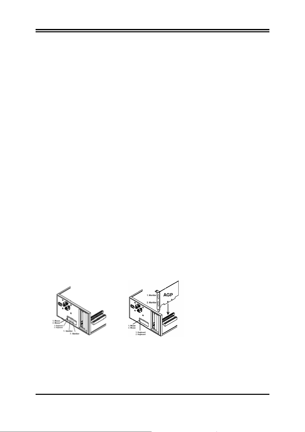
Spegnere il PC e aprire il case del computer.
Rimuovere la staffa dello slot AGP e inserire nello slot una scheda video AGP Dual Head acquistata
separatamente dal proprio rivenditore. Se la scheda madre è fornita con una doppia porta VGA integrata su
scheda, ignorare questo passaggio.
®
consente a 2 utenti di connettersi e di lavorare contemporaneamente su 2 stazioni con sessioni
1. Tastiera
2. Tastiera
1. Tastiera
2. Tastiera
Doppia porta VGA su scheda Doppia porta AGP VGA V
Collegare i due cavi Octopus forniti, uno alla porta "verde" (prima porta del mouse PS/2) e l'altro alla porta "viola"
(prima porta della tastiera PS/2) sul retro della scheda madre.
Collegare il primo e il secondo mouse al cavo Octopus collegato al connettore PS/2 "verde", quindi collegare la
prima e la seconda tastiera all'altro cavo Octopus collegato alla porta "viola". Il monitor aggiuntivo DEVE essere
collegato, altrimenti Windows non potrà rilevare e attivare il secondo monitor. A questo punto, riavviare il PC.
m7
Page 11
Installazione del software
Riavviare il PC. Windows riconosce automaticamente la nuova periferica video AGP come scheda VGA standard.
Installare prima tutti gli altri driver presenti, quindi per ultimo il driver "MagicTwin" dal CD MAGIC INSTALL.
Inserire il CD, attendere l'avvio automatico e avviare l'installazione di MagicTwin dal CD Magic Install. Se il CD
non si avvia automaticamente, fare clic su Start, Esegui e digitare D:\SETUP.EXE (dove D: è la lettera dell'unità
ottica).
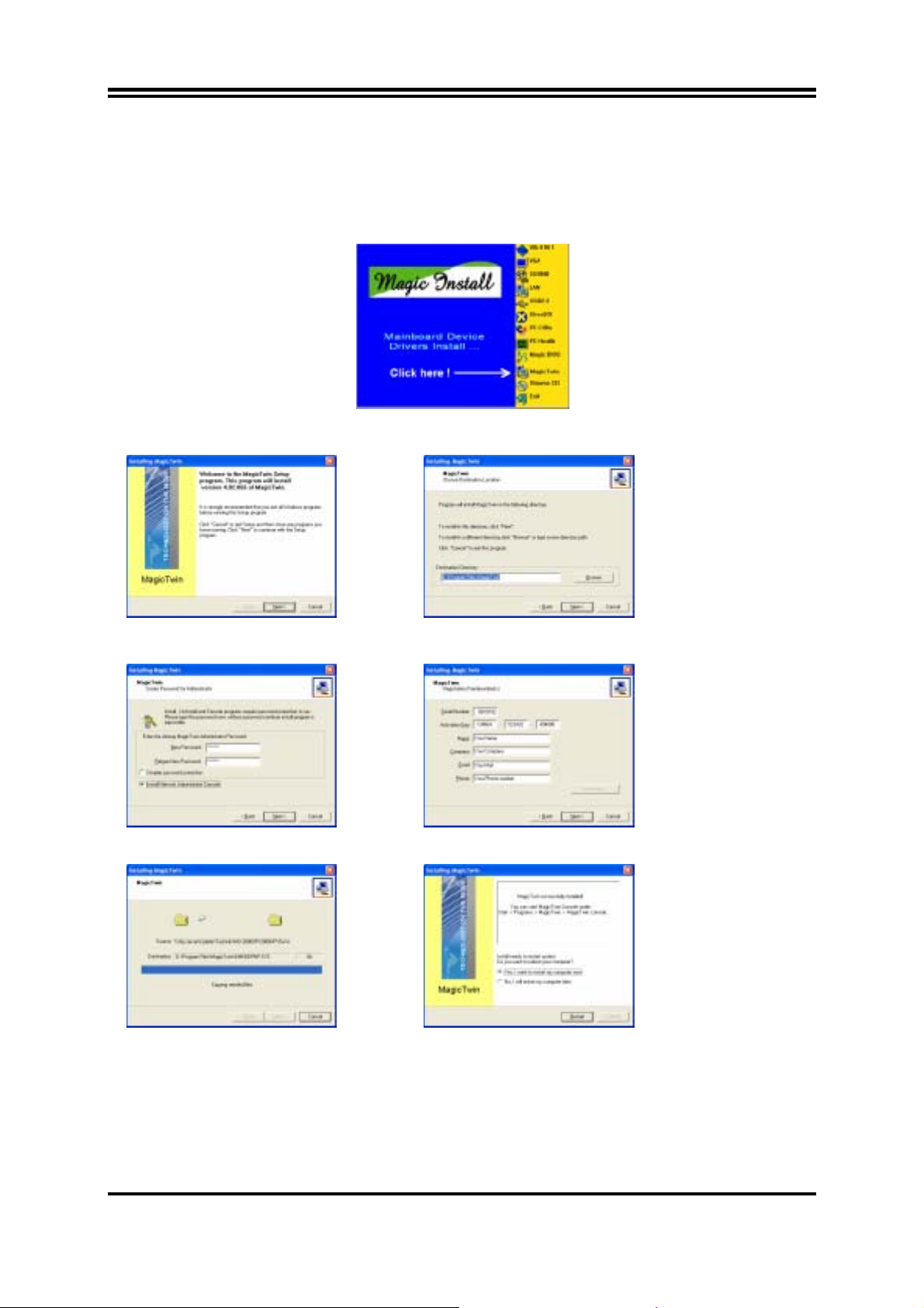
Fare clic su "MagicTwin" per aprire il menu MAGIC INSTALL. Si avvia la procedura di installazione...
Alla schermata iniziale, fare clic su "Next" Opzione: modificare il percorso di destinazione oppure
fare subito clic su "Next"
Password e Network Console, fare clic Digitare il numero di serie e l'indirizzo, quindi fare clic su "Next"
Installazione in corso, attendere... Al termine dell'operazione, scegliere "Yes" alla richiesta di riavvio del PC.
Windows viene riavviato, caricando i nuovi driver installati. MagicTwin viene attivato assegnando
automaticamente la seconda stazione al secondo monitor, alla seconda tastiera PS/2 e al secondo mouse PS/2.
Accedere a Windows e aggiungere uno o più utenti dal Pannello di controllo.
m8
Page 12
Introducción
El sistema MagicTwin es una solución interconstruida en el especial diseño de las tarjetas madre (principal) que
lo incorporan y que le permitirá la simultánea operación de 2 usuarios en el mismo computador, con una tarjeta
de video AGP de doble salida, dos cables ‘ Y ‘ para teclado y ratón tipo PS/2 y un programa con manejadores
y herramientas. Este sistema le permitirá agregar una estación de trabajo adicional corriendo Windows XP
Home o Professional ( Service Pack 1) simultáneamente .
Requerimientos del Sistema
Tarjeta Madre Jetway MagicTwin :
Adquirido en forma independiente con su Distribuidor:
2 x PS/2 cable ‘ Y ‘
CD de Instalación (Manejadores y sistema MagicTwin)
Número de serie y Llave de Activación
Procesador con velocidad igual o mayor a 1.2 Ghz
Mínimo de 256MB DRAM en memoria
Trajeta de video gráfica AGP NVIDIA con salida Doble o Dual
Windows XP edición Home ó Professional, con el Service Pack 1
2 Teclados PS/2
2 Ratones PS/2
2 Monitores
Componentes necesarios para configurar 2 usuarios
¾ Una Tarjeta madre con diseño especial de conectividad interconstruida
¾ Una Tarjeta de video gráfica AGP con salida de video doble (Adquirida con su distribuidor)
¾ Dos cables en ‘ Y ’ para conectar dos teclados y dos ratones tipo PS/2
¾ CD MAGIC INSTALL (incluyendo todos los manejadores necesarios y las herramientas para habilitar la
función 2 Usuarios en la Tarjeta madre). Además, éste contiene un programa de autodetección el cual
detecta, instala y configura el 2do. Monitor , y los 2dos. Teclado y Ratón tipo PS/2.
¾ Número de serie y Llave de activación (Impresa en la etiqueta del estuche donde se empaca el CD de
instalación)
¾ Dos monitores
¾ Dos juegos de bocinas (opcional)
Recomendaciones
¾ Microprocesador o CPU: > 1.2 GHz
¾ Mínimo de 256 MB RAM para dos estaciones corriendo simultáneamente
¾ Dos teclados estándar y dos ratones tipo PS/2 así como dos Monitores (Sonido: opcional)
¾ Disco duro y lector CD-ROM
Instalación del Sistema MagicTwin
¾ Instale Windows XP y sus correspondientes manejadores
¾ Apage su computador y destape el gabinete
¾ Retire la tapa correspondiente al conector AGP e instale la tarjeta
de video gráfica AGP con salida dual (que fue adquirida por
separado) en el conector AGP.
Si el modelo de su Tarjeta madre ya incluye el puerto de salida de
video dual, por favor omita esta paso.
¾ Retire la tapa correspondiente al conector AGP e instale la tarjeta de video gráfica AGP con salida dual
(que fue adquirida por separado) en el conector AGP.
Si el modelo de su Tarjeta madre ya incluye el puerto de salida de video dual, por favor omita esta paso.
¾ Conecte los cables ‘ Y ‘ en los conectores tipo PS/2 que se encuentran en la parte trasera de su
computador : color Verde para Ratón y color Violeta para Teclado
¾ Conecte el primer y segundo ratón al cable ‘ Y ’ que conectó al puerto PS/2 color verde, de igual forma
instale el primer y segundo teclado al cable ‘ Y ’ instalado en el conector PS/2 color Violeta. Conecte los
dos monitores a sus respectivas salidas, tenga en cuenta que el 2do monitor DEBE estar conectado, de
otra forma, Windows no lo detectará y no lo habilitará . Asegúrese que los teclados y ratones
conectados estén en condiciones de trabajo ya que de lo contrario, podría afectar el funcionamiento del
computador.
¾ Arranque su Computador . Windows automáticamente detectará el nuevo dispositivo AGP de video
como una tarjeta de video gráfica VGA estándar. Instale los manejadores de la misma antes de
instalar el sistema Magic Twin desde el CD incluido. Inserte el CD Magic Install, espere a que este
se autoejecute y empieze la instalación de los manejadores y programas de configuración de los
dispositivos integrados en la Tarjeta Madre y que serán necesarios para la operación del sistema Magic
Twin. Si al insertar el CD, éste no se autoejecuta, presione INICIO -> Ejecutar -> Unidad lector–CD :
SETUP.EXE
Dual Port AGP VGA Card
m9
Page 13
¾ Una vez que los manejadores fueron instalados, para finalizar siga los siguientes pasos :
Seleccione “MagicTwin” en el menú MAGIC INSTALL MENU cuando este aparezca. La rutina de instalación
comenzará.....
Binevenida , presione “Next” Opción: Cambie la ruta destino o presione “Next”
Teclee su Código secreto, presione “Next” Introduzca No. Serie, Llave y datos, presione “Next”
Instalación en proceso, espere… Al terminar reinicie.. (“Reboot your PC”.)
¾ Windows reiniciará y cargará los nuevos manejadores instalados. El sistema MagicTwin activará y
asignará automáticamente la 2da Estación, y los 2dos. Monitor, Teclado y Ratón.
¾ Ingrese en Windows y añada él o los usuarios adicionales utilizando el panel de control (control panel)
de Windows.
Tarjeta de Video Dual AGP.
Las tarjetas de video gráficas NVIDIA MX 440-8X, MX-4000, FX 5200 y FX5600 con salida dual, son
compatibles y soportadas por el sistema MagicTwin. Un monitor es usado por el anfitrión y el segundo es
utilizado por la estación MagicTwin. Póngase en contacto con su Distribuidor para la adquisición de cualquiera
de las tarjetas de video NVIDIA aprobadas, He aquí algunas :
1. Jetway NV18-A2-64B 2. Jetway NV34-AD-128B 3. Jetway N31X-AD-128B
4. Asustek V9520 5. Leadtek A340 6. Leadtek A180
7. MSI FX5600-TD128 8. MSI FX5200-TD128
m10
Page 14
はじめに
このベアボ-ンシステムは、マルチメディア対応のプラットフォ-ムで 2 人のユ-ザ-共有が可能です。最先
端の機器とソフトウェアを駆使し、MagicTwin
Windows 上で、選択が可能です。各 2 ユ-ザ-は、独自の Windows-XP コンピュ-タ-を持っている環境となり
ます。 通常のPCユ-ザ-は、各自、キ-ボ-ド、マウス、音響機器、モニタ-が必要になります。しかし、
本製品の場合は、機器の共有が可能で、IP も同様です。但し、本製品のユ-ザ-の必須PC環境は、CPUは、
1.0 GHz 以上、メモリは、DDR 256MB (各ユ-ザ-に対して 128MB )、デュアルの VGA ポ-トが必要です。つま
り、1 つのPCがで 2 台分の役目が可能となります。
®
シリ-ズベアボ-ンシステムは、2 ユ-ザ-を共有環境に導き
システム必須環境
MiniQ MagicTwin シリーズベアボーンシステム
2 x PS/2 keyboard・PS/2 mouse 用 Y 字ケーブル
1 x MagicTwinインストール CD (driver and digital description)
1 x シリアルナンバー・authorization code、ライセンス同意書
購入して下さい
2 x PS/2 キーボード(ケーブル、または、無線)
2 x PS/2 マウス(ケーブル、または、無線)
2 x SVGA の標準のモニタ(CRT モニタ、または、TFT モニタ)
デュアルヘッド AGP VGA
Service Pack1 がインストールされている Windows XP HOME または、Professional
CPUは 1,2GHz
メモリは 256MB 搭載
MagicTwinハードウェア
システム要求が満たしている事を推奨します。全てのMagic Twinシステムは2VGAポートが必要です。別売りで
デュアルヘッドAGP VGAカードを購入して下さい。取り付ける為に以下のいずれかを準備して下さい: a). デュア
ルポートが付いているVGA b). デュアルオンボードVGAカード
パッケージを確認してお客様の必要なデュアルVGAポートをご用意下さい。
AGPスロットブラケットを取り外し、AGPスロットに準備したAGP VGAカードを挿入して下さい。 b)の場合はこ
のステップを飛ばして下さい。
Onboard Dual Port VGA Dual Port AGP VGA Card
マウス用・キーボード用それぞれのY字ケーブルをPS/2マウスポート(グリーン)・PS/2キーボードポート(紫)
に 接続して下さい。2セットのマウスとキーボードを必ず一つのY字ケーブルで接続して下さい。モニタも必ず
2つ接続して下さい。
ソフトウェアのインストール
PC を起動して下さい。Windows は標準の VGA カードとして新しい AGP VGA デバイスを自動的に検出します。
Magic Twin ドライバー以外のドライバーを先にインストールして下さい。最後に Magic Twin インストール CD
の Magic Twin ドライバーをインストールして下さい。もし CD がオートラン(自動再生)しない場合は
Start>Run>CD ドライブ>SETUP.EXE をクリックして下さい。
m11
Page 15
“MagicTwin”をクリックして下さい。
Welcome 画面で“Next”をクリックして下さい。 オプション:プログラムを保存したい場所を選択す
るか、“Next”をクリックして下さい。
Password と Network Console を入力し、 シリアルと必要事項を入力し、“Next”をクリックし
“Next”をクリックして下さい。 て下さい。
インストールが始まります。 “Restart”ボタンをクリックして、再起動して下さい。
ウィンドウズは、新しいインストールされたドライバーをロードします。MagicTwin はアクティブになり、そして自動的に
セカンドステーションにモニタ、PS/2 マウスを指定します。
產品介紹
MagicTwin 為建構於具備雙視訊輸出連接器之 AGP 顯示卡,雙 PS/2 介面滑鼠鍵盤 Y 型纜線,與一套軟體〈驅動程
式與工具程式〉之特殊設計主機板的雙使用者解決方案。它允許您增加額外之工作站來模擬運行 Windows XP 家
用或專業版(Service Pack 1)。
系統需求
捷波 MagicTwin 主機板
2 x PS/2 Y 型纜線
安裝光碟片〈驅動程式與工具程式〉
m12
Page 16
產品序號與啟動金鑰
需另行於經銷商處購入
>=1.2 GHz 中央處理器
最小 256MB 之系統記憶體
NVIDIA 雙視訊輸出連接器之顯示卡
Windows XP 家用或專業版(Service Pack 1)
2 x PS/2 介面滑鼠
2 x PS/2 介面鍵盤
2 x 顯示器
設定雙使用者系統的必要元件
¾ 一張具備內建連接認證晶片的特殊設計主機板
¾ 一張具備雙視訊輸出連接器之顯示卡〈需另行於經銷商處購入〉
¾ 兩條 PS/2 介面滑鼠鍵盤 Y 型纜線
¾ MAGIC 安裝光碟片〈包括您所需要之全部驅動程式與部分工具程式用以驅動主機板之雙使用者功能〉。
此外此光碟包括一套用以偵測、安裝與指定相關第二顯示器及第二組 PS/2 介面滑鼠鍵盤之自動偵測軟件
¾ 一組產品序號與啟動金鑰〈印於黏貼在 CD 封套頂端之貼紙上〉
¾ 兩台顯示器
¾ 兩組揚聲器〈選購〉
建議之系統需求
¾ 中央處理器>1GHz
¾ 最小 256MB 之系統記憶體以供兩工作站同時模擬運行
¾ 兩組標準之 PS/2 介面滑鼠鍵盤與兩台顯示器
¾ 硬碟機與光碟機
MagicTwin 之安裝
¾ 建議您完全重新安裝您的 Windows XP 作業系統與其他相關之驅動程式
¾ 關閉您的電腦並將機箱打開
¾ 移除 AGP 匯流排之機箱隔板並且插入一片另行於經銷商處購
入之雙視訊輸出連接器之顯示卡於 AGP 匯流排上。若您購買之主
機板已經內建雙視訊輸出連接器,請跳過此一步驟。
雙視訊輸出連接器之顯示卡
¾ 將隨產品附贈之 Y 型纜線分別插入位於主機板後方之綠色連接埠〈亦即 PS/2 介面滑鼠連接埠〉與紫色連
接埠〈亦即 PS/2 介面鍵盤連接埠〉
¾ 連接第一組與第二組滑鼠於插入綠色 PS/2 介面連接埠 Y 型纜線及連接第一組與第二組鍵盤於插入綠色
PS/2 介面連接埠 Y 型纜線。第二台顯示器務必安裝妥當,否則視窗作業系統將無法偵測與驅動第二台顯
示器。確定第二組滑鼠與鍵盤運作正常,他們將會影響主機之主控台。
¾ 啟動您的電腦,視窗作業系統將會自動偵測到新安裝之顯示裝置為標準之 VGA-card。請於安裝 MAGIC
INSTALL 光碟 MagicTwin 軟體前先行安裝完所有之驅動程式。插入光碟片,等待其自動執行除了
MagicTwin 軟體外,依序自 MAGIC INSTALL 光碟中安裝所有之驅動程式。若光碟片沒有自動執行,請
執行 開始-> 執行 -> 光碟機-> SETUP.EXE。
¾ 安裝完所有的驅動程式之後,最後一如下步驟開始安裝 MagicTwin 軟體:
m13
Page 17
當 MAGIC INSTALL MENU 出現時,請執行“MagicTwin”,安裝程序將會開始…….
歡迎頁,請點選 “Next”〈下一步〉 選項:改變安裝目的資料夾或點選“Next”〈下一步〉
密碼與網路主控台,點選 “Next”〈下一步〉 輸入產品序號與地址,點選 “Next”〈下一步〉
安裝執行中,點選 “Next”〈下一步〉 之後,請重新啟動您的電腦
¾ 視窗作業系統正在重新啟動並安裝新的驅動程式,啟動完成後之 MagicTwin 軟體將自動將工作站 2 指定
給第二台顯示器與第二組之 PS/2 介面滑鼠鍵盤。
¾ 請登入視窗作業系統並於主控台中增加一個或多個使用者。
具備雙視訊輸出連接器之顯示卡
MagicTwin 系統支援 NVIDIA MX 440-8X, MX-4000, FX 5200 與 FX5600 雙視訊輸出連接器之顯示卡。連接之一台
顯示器為主機使用,而另一台顯示器為 MagicTwin 工作站使用。請與您的經銷商聯繫並購買下列為 MagicTwin 系
統支援之雙視訊輸出連接器 AGP 顯示卡:
1. 捷波 NV18-A2-64B 2. 捷波 NV34-AD-128B 3. 捷波 N31X-AD-128B
4. 華碩 V9520 5. 麗台 A340 6. 麗台 A180
7. 微星 FX5600-TD128 8. 微星 FX5200-TD128
产品介绍
m14
Page 18
MagicTwin 为建构于具备双视讯输出连接器之 AGP 显示卡,双 PS/2 接口鼠标键盘 Y 型缆线,与一套软件〈驱动程序
与工具程序〉之特殊设计主机板的双使用者解决方案。它允许您增加额外之工作站来仿真运行 Windows XP 家用或
专业版(Service Pack 1)。
系统需求
捷波 MagicTwin 主机板
2 x PS/2 Y 型缆线
安装光盘片〈驱动程序与工具程序〉
产品序号与激活金钥
需另行于经销商处购入
>=1.2 GHz 中央处理器
最小 256MB 之系统内存
NVIDIA 双视讯输出连接器之显示卡
Windows XP 家用或专业版(Service Pack 1)
2 x PS/2 接口鼠标
2 x PS/2 接口键盘
2 x 显示器
设定双使用者系统的必要组件
¾ 一张具备内建连接认证芯片的特殊设计主机板
¾ 一张具备双视讯输出连接器之显示卡〈需另行于经销商处购入〉
¾ 两条 PS/2 接口鼠标键盘 Y 型缆线
¾ MAGIC 安装光盘片〈包括您所需要之全部驱动程序与部分工具程序用以驱动主机板之双使用者功能〉。此
外此光盘包括一套用以侦测、安装与指定相关第二显示器及第二组 PS/2 接口鼠标键盘之自动侦测软件
¾ 一组产品序号与激活金钥〈印于黏贴在 CD 封套顶端之贴纸上〉
¾ 两台显示器
¾ 两组扬声器〈选购〉
建议之系统需求
¾ 中央处理器>1GHz
¾ 最小 256MB 之系统内存以供两工作站同时仿真运行
¾ 两组标准之 PS/2 接口鼠标键盘与两台显示器
¾ 硬盘机与光驱
MagicTwin 之安装
¾ 建议您完全重新安装您的 Windows XP 操作系统与其它相关之驱动程序
¾ 关闭您的计算机并将机箱打开
¾ 移除 AGP 总线之机箱隔板并且插入一片另行于经销商处购入之双视讯输出连接器之显示卡于 AGP 总线上。
若您购买之主机板已经内建双视讯输出连接器,请跳过此一步骤。
双视讯输出连接器之显示卡
¾ 将随产品附赠之 Y 型缆线分别插入位于主机板后方之绿色连接埠〈亦即 PS/2 接口鼠标连接端口〉与紫色
连接埠〈亦即 PS/2 接口键盘连接端口〉
¾ 连接第一组与第二组鼠标于插入绿色 PS/2 接口连接端口 Y 型缆线及连接第一组与第二组键盘于插入绿色
PS/2 接口连接端口 Y 型缆线。第二台显示器务必安装妥当,否则窗口操作系统将无法侦测与驱动第二台
显示器。确定第二组鼠标与键盘运作正常,他们将会影响主机之主控台。
¾ 激活您的计算机,窗口操作系统将会自动侦测到新安装之显示装置为标准之 VGA-card。请于安装 MAGIC
INSTALL 光 盘 MagicTwin 软件前先行安装完所有之驱动程序。插入光盘片,等待其自动执行除了
MagicTwin 软件外,依序自 MAGIC INSTALL 光盘中安装所有之驱动程序。若光盘片没有自动执行,请执行
开始-> 执行 -> 光驱-> SETUP.EXE。
¾ 安装完所有的驱动程序之后,最后一如下步骤开始安装 MagicTwin 软件:
m15
Page 19
当 MAGIC INSTALL MENU 出现时,请执行“MagicTwin”,安装程序将会开始…….
欢迎页,请点选 “Next”〈下一步〉 选项:改变安装目的资料夹或点选“Next”〈下一步〉
密码与网络主控台,点选 “Next”〈下一步〉 输入产品序号与地址,点选 “Next”〈下一步〉
安装执行中,点选 “Next”〈下一步〉 之后,请重新激活您的计算机
¾ 窗口操作系统正在重新激活并安装新的驱动程序,激活完成后之 MagicTwin 软件将自动将工作站 2 指定给
第二台显示器与第二组之 PS/2 接口鼠标键盘。
¾ 请登入窗口操作系统并于主控台中增加一个或多个使用者。
具备双视讯输出连接器之显示卡
MagicTwin 系统支持 NVIDIA MX 440-8X, MX-4000, FX 5200 与 FX5600 双视讯输出连接器之显示卡。连接之一台显
示器为主机使用,而另一台显示器为 MagicTwin 工作站使用。请与您的经销商联系并购买下列为 MagicTwin 系统支
持之双视讯输出连接器 AGP 显示卡:
1. 捷波 NV18-A2-64B 2. 捷波 NV34-AD-128B 3. 捷波 N31X-AD-128B
4. 华硕 V9520 5. 丽台 A340 6. 丽台 A180
7. 微星 FX5600-TD128 8. 微星 FX5200-TD128
m16
Page 20

Chapter 1
Introduction
The special designed 2-user motherboard allows two users to share the computing power of a
single PC system. With integrated connectivity hardware onboard, the motherboard comes
with innovative software, the MagicTwin®, allowing 2 users to be connected to it and runs up
to two stations directly from it simultaneously. The unique and copyright-protected
MagicTwin® technology makes each of the 2 users feel like having himself his own WindowsXP computer. Each user needs to have himself his own keyboard, mouse, sound device, and
monitor. All remaining PC hardware are shared, even the IP.
Both users can operate on their own station concurrently just like the operation of a standard
PC. There is no obvious delay because of the Time-slicing/Multiplexing technology built-in.
Each user gets an exact and extremely short defined moment to access to the PC system,
devices, applications and Windows itself. Resources are only claimed for nanoseconds at a
time, usually from electronic memory, or cache. Both users get from Windows and the PC,
what they really need when they need it! The MagicTwin solution turns the single PC into a
cost-effective multi-user system.
The setup is intuitive and easy. In only a few minutes, users can install and start using their
new workstation. No network administrator is needed as everything to network the
workstations together is done automatically with the MagicTwin software. You can add
immediately additional user station to the single system and turn one PC into two.
System Requirement
Jetway MagicTwin Motherboard:
2 x PS/2 Y-cable
Install CD (Driver and MagicTwin)
Serial Number and Activation Key
Purchased Separately from Dealer:
>=1.2 GHz Processor
Min 256MB DRAM
NVIDIA Dual Head AGP Graphic Card
Windows XP Home, Prof. w/ SP1
2 x PS/2 Keyboards
2 x PS/2 Mice
2 x Monitors
1
Page 21

Introduction of S755TWIN Motherboard
1-1 Feature of motherboard
The S755TWIN motherboard is design for use 64bit AMD Athlon64 (K8) Processor in 754
Pin HyperTrnsport Processor with the SiS 755/963L Chipset delivers a high performance and
professional desktop platform solution. Which utilize the Socket 754 design and the memory
size expandable to 2.0GB.
The motherboard use the newest SiS 755 North bridge chipset supports 800MHz System Bus
in data transfer rate, and provided 200/166/133MHz SDRAM clock frequency support
DDR400/DDR333/DDR266 SDRAM. The motherboard embedded SiS 963L south bridgeand
offers two parallel ULTRA ATA 133 interface to provide speedier HDD throughout that
boosts overall system performance.
The motherboard integrated SiS 180 Serial-ATA IDE controller provided two Serial-ATA
port and one Parallel Ultra ATA port (two devices), supports Ultra ATA/Serial ATA,
Ultra/Serial ATA RAID 0 or 1, Ultra/Serial ATA Raid 0+1 meet future IDE demand increase
the data transfer rate.
For those wanting even greater graphic performance, an AGP slot is included on the board
(For 1.5V AGP card only. No for 3.3V or Universal AGP card). This AGP slot will
support either a 4X/8X VGA card compliant to AGP specification 2.0/3.0
The motherboard including Fast Ethernet MAC and PHY chip support 10Mb/s, 100Mb/s Base
transfer rate.
The motherboard also has an integrated PCI 6-channel Audio chip on board support 6-channel
3D surround positioning Audio which is fully compatible with Sound Blaster Pro that gives
you the best sound quality and compatibility. The motherboard provided SPDIF-In/ SPDIFOut optical function support SPDIF device.
With USB control as well as capability of expanding to 6 USB2.0 function ports, these
motherboards meet future USB demand also these motherboard have built-in hardware
monitor function. This will monitor and protect your computer. These motherboards special
design in hardware to protect BIOS from virus crash BIOS data.
These motherboards provide special function in BIOS Setup to setting CPU Host clock step
by step increasing let users to approach over clocking.
These motherboards provided high performance & meet future specification demand. It is
really wise choice for your computer.
1-2 Specification
2
Page 22

Spec Description
Design
Chipset ∗
CPU Socket
(mPGA478B Socket)
Memory Socket ∗
Expansion Slot &
Headers
Integrate IDE ∗
Serial-ATA IDE
LAN On Board
Audio ∗
BIOS
Multi I/O ∗
ATX form factor 4 layers PCB size: 30.5x21.5cm
∗
SiS 755 K8HT AGP/MuTIOL Bridge (North Bridge) Chipset
SiS 963L MuTIOL 1G Media I/O (South Bridge) chipset
∗
Support 64bit AMD Athlon64 754-Pin package utilizes Flip-
∗
Chip Pin Grid Array package processor
Support CPU Frequency 800MHz
∗
Support up to 3200+, 3400+ processor
∗
Reserves support for future AMD Athlon64 754-pin processors
∗
184-pin DDR SDRAM module socket x2
Support Dual channel DDR266/DDR333/DDR400 DDR
∗
SDRAM
Expandable to 2.0GB
∗
AGP slot x1 for AGP 0.8V/1.5V standard only, support AGP
∗
2.0/3.0 & 4X/8X mode
32-bit PCI slot x 5
∗
CNR slot x1
∗
Two IDE controllers support PCI Bus Mastering, ATA
PIO/DMA and the ULTRA DMA 66/100/133 functions that
deliver the data transfer rate up to 100/133 MB/s
SiS 180 Serial-ATA Controller provide two Serial ATA ports
∗
support 150Mb/s data transfer rate and one Parallel ATA133
port support 133Mb/s data transfer rate
Support Ultra Mode Function
∗
Support RAID 0 or 1, RAID 0+1 function
∗
Integrated LAN MAC with LAN PHYceiver
∗
Supports 10/100 Mb/sec data transfer rate
∗
ALC AC97” 2.2 Codec chip integrated
Support 6-channel 3D surround & Positioning Audio
∗
SPDIF-In/ SPDIF-Out Optical support
∗
Audio driver and utility included
∗
Award 2MB Flash ROM
∗
PS/2 keyboard and PS/2 mouse connectors
Floppy disk drive connector x1
∗
Parallel port x1, Serial port x2
∗
USB 2.0 connector x6, headers x2 (connecting cable option)
∗
Audio connector Line-in, Line-out, MIC & Game Port Header
∗
3
Page 23

1-3 Performance List
The following performance data list is the testing result of some popular benchmark testing
programs. These data are just referred by users, and there is no responsibility for different
testing data values gotten by users (the different Hardware & Software configuration will
result in different benchmark testing results.)
Performance Test Report
CPU:
DRAM:
VGA Card:
Hard Disk Driver:
BIOS:
OS:
AMD K8 –ATHLON 64 3200+
256MB DDR400 SDRAM x1 (Winbond)
ATi 9700 Pro (1024x768x32bit Color)
IBM IC35L040AVVN07-0 (ATA-100 7200RPM)
Award Optimal default
Win XP Professional (Service Pack 1)
200/200MHz
3D Mark 2001SE
Win Mark 2003
PC Mark 2002
CPU/Memory/HDD
Business Winstone 2002
SISOFT Sandra 2003 :
Dhrystone ALU MIPS 7225
Whetstone FPU/iSEE2 MFLOPS 3038/4059
RAM Int Buffered iSSE2 MB/S 3011
RAM Float Buffered iSSE2 MB/S 3013
17751
5144
6555/8739/1259
41.8
Integer SSE2 IT/S 8661
Floating-Point SSE2 IT/S 11331
SUPER-PI 45
WCPUID System/CPU Clock 199.99/1999.94
4
Page 24

i
r
r
1-4 Layout Diagram & Jumper Setting
PRINT
PS/2 Mouse
LAN
MIC
LINE-IN
PS/2 Keyboard
ATX 12V Power Connector
K/B Power ON Jumper
PS2 KB/Mouse Port
PC99 Back Panel
USB Power ON Jumper
ATX Power Connector
Audio Connector (CN1)
(JP13)
(JP11)
USB Port
LAN Connector
SPDIF Connector
Front Panel Audio
LINE-OUT
COM1 COM2 USB1
UL_B
DDR DIMMx2
CPU Socket
CPU FAN
SiS 755 Chipset
AGP 8X Slot
SYSFAN
ATA 133 IDE Connector
CD Audio
PCI Slot
ITE 8705 I/O Chip
GAME Port Connector
2MBit Flash ROM BIOS
COM2 Connector
Wake On LAN
USB3 Power ON Jumpe
(JP12)
SiS 963L Chip
Serial-ATA Connector(SATA1, 2)
Floppy Connector
ATA 133 IDE Connector
S 180 Serial ATA Controlle
S
Clear CMOS (JP9)
Power LED Connector
Speak Connector
IR Connector
USB Port (USB3)
Front Panel Connector
5
Page 25

Jumpers
Jumper Name Description Page
JP9 CMOS RAM Clear 3-pin Block P.6
JP13 Keyboard Power On Enable/Disabled 3-pin Block P.7
JP11/JP12 USB Power On Enable/Disabled 3-pin Block P.7
Connectors
Connector Name Description Page
PWR2 ATX Power Connector 20-pin Block P.11
PWR1 ATX 12V Power Connector 4-pin Block P.11
USB1/USB2 USB Port Connector 4-pin Connector
LAN LAN Connectors RJ-45 Connector P.12
KBMS
(PS2 KB/MOUSE)
PS/2 Mouse & PS/2 Keyboard
Connector
6-pin Female P.12
PRINT Parallel Port Connector 25-pin Female P.12
CN1 Audio Line In/Out MIC Connector 3 phone jack Connector P.12
COM1/COM2 Serial Port COM1/COM2 Connector 9-pin Connector P.12
FDC Floppy Driver Connector 34-pin Block P.13
IDE1/IDE2/IDE3 Primary/Secondary/Third IDE
40-pin Block P.13
Connector
SATA1, SATA2 Serial-ATA Port Connector 7-pin Block P.14
P.12
Headers
Header Name Description Page
AUDIO Line-Out, MIC Headers 9-pin Block P.14
USB3 USB Port Headers 4-pin Block P.15
SPEAK Speaker connector 4-pin Block P.15
FP
(Power LED/Reset/
IDE LED/ Power Button)
Front Panel Header
(including Power LED/ IDE activity LED/
Reset switch / Power On Button lead)
9-pin Block P.15
WOL Wake On-LAN Headers 3-pin Block P.16
SYSFAN, CPUFAN FAN Speed Headers 3-pin Block P.16
IR IR infrared module Headers 5-pin Block P.16
CDIN CD Audio-In Headers 4-pin Block P.17
GAME Game Port Header 15-pin Block P.17
SPDIF Optical In/Out Header 10-pin Block P.17
Expansion Sockets
Socket/Slot Name Description Page
ZIF Socket 754 CPU Socket 754-pin mPGAB Athlon64 CPU Socket P.8
DIMM1, DIMM2 DDR Module Socket 184-pin DDR SDRAM Module
Expansion Socket
PCI1 ∼ PCI5
PCI Slot 32-bit PCI Local Bus Expansion slots P.9
AGP AGP 4X/8X Mode Slot AGP Expansion Slot P.10
P.8
6
Page 26

Chapter 2
Hardware installation
2-1 Hardware installation Steps
Before using your computer, you had better complete the following steps:
1. Check motherboard jumper setting
2. Install CPU and Fan
3. Install System Memory (DIMM)
4. Install Expansion cards
5. Connect IDE and Floppy cables, Front Panel /Back Panel cable
6. Connect ATX Power cable
7. Power-On and Load Standard Default
8. Reboot
9. Install Operating System
10. Install Driver and Utility
2-2 Checking Motherboard’s Jumper Setting
(1) CMOS RAM Clear (3-pin) : JP9
A battery must be used to retain the motherboard configuration in CMOS RAM short 2-3
pins of JP9 to store the CMOS data.
To clear the CMOS, follow the procedure below:
1. Turn off the system and unplug the AC power
2. Remove ATX power cable from ATX power connector
3. Locate JP9 and short pins 1-2 for a few seconds
4. Return JP9 to its normal setting by shorting pins 2-3
5. Connect ATX power cable back to ATX power connector
Note: When should clear CMOS
1. Troubleshooting
2. Forget password
3. After over clocking system boot fail
13
JP9
1-2 closed Clear CMOS
CMOS RAM Clear Setting
1 3
JP9
2-3 closed Normal (Default)
7
Page 27

(2) Keyboard/USB Power On function Enabled/Disabled: JP13/JP11, JP12
When setting Enabled you can using keyboard by key in password/USB device to power
on system.
JP13
JP13
JP11
13
13
JP11
1
3
JP13 1-2 closed K/B Power ON Disabled (Default)
JP13 2-3 closed K/B Power ON Enabled
JP11 1-2 closed USB Power On Disabled (Default)
1
JP11 2-3 closed USB Power On Enabled
3
JP12
JP12
13
JP12 1-2 closed USB3 Power ON Disabled (Default)
13
JP12 2-3 closed USB3 Power ON Enabled
2-3 Install CPU
2-3-1 Glossary
Chipset (or core logic) - two or more integrated circuits which control the interfaces between
the system processor, RAM, I/O devises, and adapter cards.
Processor slot/socket - the slot or socket used to mount the system processor on the
motherboard.
Slot (AGP, PCI, ISA, RAM) - the slots used to mount adapter cards and system RAM.
AGP - Accelerated Graphics Port - a high speed interface for video cards; runs at 1X
(66MHz), 2X (133MHz), or 4X (266MHz).
PCI - Peripheral Component Interconnect - a high speed interface for video cards, sound
cards, network interface cards, and modems; runs at 33MHz.
ISA - Industry Standard Architecture - a relatively low speed interface primarily used for
sound cards and modems; runs at approx. 8MHz.
Serial Port - a low speed interface typically used for mouse and external modems.
Parallel Port - a low speed interface typically used for printers.
PS/2 - a low speed interface used for mouse and keyboards.
USB - Universal Serial Bus - a medium speed interface typically used for mouse, keyboards,
scanners, and some digital cameras.
Sound (interface) - the interface between the sound card or integrated sound connectors and
speakers, MIC, game controllers, and MIDI sound devices.
LAN (interface) - Local Area Network - the interface to your local area network.
BIOS (Basic Input/Output System) - the program logic used to boot up a computer and
establish the relationship between the various components.
Driver - software, which defines the characteristics of a device for use by another device or
other software.
Processor - the "central processing unit" (CPU); the principal integrated circuit used for doing
the "computing" in "personal computer"
Front Side Bus Frequency -
by the clock generator for CPU, DRAM and PCI BUS.
CPU L2 Cache -
the flash memory inside the CPU, normally Athlon CPU has 256K or above,
while Duron will have 64K.
the working frequency of the motherboard, which is generated
8
Page 28

2-3-2 About AMD Athlon64 754-pin CPU
This motherboard provides a 754-pin surface mount, Zero Insertion Force (ZIF) socket,
referred to as the mPGA754 socket supports AMD Athlon64 processor in the 754 Pin package
utilizes Flip-Chip Pin Grid Array package technology.
The CPU that comes with the motherboard should have a cooling FAN attached to prevent
overheating. If this is not the case, then purchase a correct cooling FAN before you turn on
your system.
WARNING!
Be sure that there is sufficient air circulation across the processor’s heatsink and
CPU cooling FAN is working correctly, otherwise it may cause the processor and
motherboard overheat and damage, you may install an auxiliary cooling FAN, if
necessary.
To install a CPU, first turn off your system and remove its cover. Locate the ZIF socket and
open it by first pulling the level sideways away from the socket then upward to a 90-degree
angle. Insert the CPU with the correct orientation as shown below. The notched corner
should point toward the end of the level. Because the CPU has a corner pin for two of the
four corners, the CPU will only fit in the orientation as shown.
Socket 754
CPU ZIF mPGAB Socket
Colden Arrow
When you put the CPU into the ZIF socket. No force require to insert of the CPU, then press
the level to Locate position slightly without any extra force.
2-4 Install Memory
This motherboard provides two 184-pin DUAL INLINE MEMORY MODULES (DIMM)
sites for memory expansion available from minimum memory size of 64MB to maximum
memory size of 2.0GB DDR SDRAM.
Valid Memory Configurations
Bank 184-Pin DIMM PCS Total Memory
Bank 0, 1 (DIMM1) DDRDDR266/DDR333/DDR400
DDR SDRAM Module
Bank 2, 3 (DIMM2) DDRDDR266/DDR333/DDR400
DDR SDRAM Module
Total System Memory (Max. 2.0GB) 2
9
X1
X1
64MB∼1.0GB
64MB∼1.0GB
64MB∼2.0GB
Page 29

Generally, installing DDR SDRAM modules to your motherboard is very easy, you can refer
to figure 2-4 to see what a 184-Pin DDR266/DDR333/DDR400 DDR SDRAM module looks
like.
DIMM1 (BANK0+BANK1)
DIMM2 (BANK2+BANK3)
NOTE!
WARNING!
When you install DIMM module fully into the DIMM socket the eject tab should be
locked into the DIMM module very firmly and fit into its indention on both sides.
For the DDR SDRAM CLOCK is set at 200MHz, use only DDR400-compliant DDR
Modules. When this motherboard operate at 200Mhz, most system will not even
boot if non-compliant modules are used because of the strict timing issues, if your
SDR Modules are not DDR266-compliant, set the DDR SDRAM clock to 133MHz
to ensure system stability.
2-5 Expansion Cards
WARNING!
Turn off your power when adding or removing expansion cards or other system
components. Failure to do so may cause severe damage to both your motherboard
and expansion cards.
Figure 2-4
2-5-1 Procedure For Expansion Card Installation
1. Read the documentation for your expansion card and make any necessary hardware or
software setting for your expansion card such as jumpers.
2. Remove your computer’s cover and the bracket plate on the slot you intend to use.
3. Align the card’s connectors and press firmly.
4. Secure the card on the slot with the screen you remove above.
5. Replace the computer system’s cover.
6. Set up the BIOS if necessary.
7. Install the necessary software driver for your expansion card.
2-5-2 Assigning IRQs For Expansion Card
Some expansion cards need an IRQ to operate. Generally, an IRQ must exclusively assign to
one use. In a standard design, there are 16 IRQs available but most of them are already in use.
Standard Interrupt Assignments
10
Page 30

IRQ Priority Standard function
0 N/A System Timer
1 N/A Keyboard Controller
2 N/A Programmable Interrupt
3 * 8 Communications Port (COM2)
4 * 9 Communications Port (COM1)
5 * 6 Sound Card (sometimes LPT2)
6 * 11 Floppy Disk Controller
7 * 7 Printer Port (LPT1)
8 N/A System CMOS/Real Time Clock
9 * 10 ACPI Mode when enabled
10 * 3 IRQ Holder for PCI Steering
11 * 2 IRQ Holder for PCI Steering
12 * 4 PS/2 Compatible Mouse Port
13 N/A Numeric Data Processor
14 * 5 Primary IDE Channel
15 * 1 Secondary IDE Channel
* These IRQs are usually available for ISA or PCI devices.
2-5-3 Interrupt Request Table For This Motherboard
Interrupt request are shared as shown the table below:
INT A INT B INT C INT D INT E INT F INT G INT H
Slot 1
Slot 2
Slot 3
Slot 4
Slot 5
Onboard LAN
Onboard USB 1
Onboard USB 2
Onboard USB 3
Sound
√
√
√
√
√
√
√
√
√
√
IMPORTANT!
If using PCI cards on shared slots, make sure that the drivers support “Shared
IRQ” or that the cards don’t need IRQ assignments. Conflicts will arise between
the two PCI groups that will make the system unstable or cards inoperable.
2-5-4 AGP Slot
This motherboard provides an AGP Slot, only support the 1.5V 4X/0.8V 8X AGP VGA card.
Do not use AGP 2X card (3.3V) in this motherboard. It will burn and damage the motherboard due to
chipset can not support AGP 2X (3.3V).
IMPORTANT!
Before you plug-in AGP card, please make sure the following notice is fully
understood and practiced. If your AGP card has “AGP 4X notch (show
below) please make sure your AGP card is AGP 4X/8X (1.5V/0.8V) not AGP
2X (3.3V)
11
Page 31

2x notch 4x notch
Example 1:
SiS 305 & ATi Rage 128 Pro AGP card those golden finger is compatible with
AGP SLOT
2X/4X mode AGP slot, but only can support 2X (3.3V) only. If you install these
cards in Intel® 865 based motherboard it will burn and damage the motherboard.
Example 2:
We also find Diamond Vipper V770 golden finger is design for 2X/4X mode AGP
Slot. It can be adjusted the jumper for AGP 2X (3.3V) or AGP 4X (1.5V). But the
factory default setting is 2X (3.3V). If you install this AGP card in motherboard
without change the jumper setting to 4X (1.5V), it will burn the motherboard.
2-6 Connectors, Headers
2-6-1 Connectors
(1) Power Connector (20-pin block) : PWR2
ATX Power Supply connector. This is a new defined 20-pins connector that usually comes
with ATX case. The ATX Power Supply allows to use soft power on momentary switch that
connect from the front panel switch to 2-pins Power On jumper pole on the motherboard.
When the power switch on the back of the ATX power supply turned on, the full power will not
come into the system board until the front panel switch is momentarily pressed. Press this
switch again will turn off the power to the system board.
PIN ROW2 ROW1
1 3.3V 3.3V
2 -12V 3.3V
3 GND GND
4 Soft Power On 5V
5 GND GND
6 GND 5V
7 GND GND
8 -5V Power OK
9 +5V +5V (for Soft Logic)
Pin 1
10 +5V +12V
(2) ATX 12V Power Connector (4-pin block) : PWR1
This is a new defined 4-pins connector that usually comes with ATX Power Supply. The
ATX Power Supply which fully support Pentium 4 processor must including this
connector for support extra 12V voltage to maintain system power consumption.
Without this connector might cause system unstable because the power supply can not
provide sufficient current for system.
12
Page 32

Pin 1
(3) USB Port connector: USB1, USB2
The connectors are 4-pin connector that connect USB devices to the system board.
(4) LAN Port connector: LAN
This connector is standard RJ45 connector for Network connector.
(5) PS/2 Mouse & PS/2 Keyboard Connector: KBMS (PS2 KB/MOUSE)
The connectors for PS/2 keyboard and PS/2 Mouse.
(6) Parallel Port Connector (25-pin female): PRINT
Parallel Port connector is a 25-pin D-Subminiature Receptacle connector. The On-board
Parallel Port can be disabled through the BIOS SETUP. Please refer to Chapter 3
“INTEGRATED PERIPHERALS SETUP” section for more detail information.
(7) Audio Line-In, Lin-Out, MIC Connector : CN1
This Connector are 3 phone Jack for LINE-OUT, LINE-IN, MIC
Line-out :
Line-in :
Audio input to sound chip
MIC :
Audio output to speaker
Microphone Connector
(8) Serial Port COM1: COM1/COM2
COM1/COM2 is the 9-pin D-Subminiature mail connector. The On-board serial port can be
disabled through BIOS SETUP. Please refer to Chapter 3 “INTEGRATED PERIPHERALS
SETUP” section for more detail information.
USB1PS/2 Mouse PRINT
LAN
MIC
LINE-IN
LINE-OUT
PS/2 Keyboard UL_B
COM1
COM2
(9) Floppy drive Connector (34-pin block): FDC
This connector supports the provided floppy drive ribbon cable. After connecting the single plug
end to motherboard, connect the two plugs at other end to the floppy drives.
FDC
Pin 1
Floppy Drive Connector
13
Page 33

(10) Primary IDE Connector (40-pin block): IDE1
This connector supports the provided IDE hard disk ribbon cable. After connecting the
single plug end to motherboard, connect the two plugs at other end to your hard disk(s). If
you install two hard disks, you must configure the second drive to Slave mode by setting its
jumpers accordingly. Please refer to the documentation of your hard disk for the jumper
settings.
(11) Secondary IDE Connector (40-pin block): IDE2
This connector connects to the next set of Master and Slave hard disks. Follow the same
procedure described for the primary IDE connector. You may also configure two hard
disks to be both Masters using one ribbon cable on the primary IDE connector and another
ribbon cable on the secondary IDE connector.
IDE2
Two hard disks can be connected to each connector. The first HDD is referred to as the
•
Pin 1
Pin 1
IDE1
“Master” and the second HDD is referred to as the “Slave”.
For performance issues, we strongly suggest you don’t install a CD-ROM or DVD-ROM
•
drive on the same IDE channel as a hard disk. Otherwise, the system performance on this
channel may drop.
(12) Third IDE Connector (40-pin block): IDE3
This connector supports the provided IDE hard disk ribbon cable. After connecting the
single plug end to motherboard, connect the two plugs at other end to your hard disk(s).
Please refer to the documentation of your hard disk for the jumper settings.
IDE3
Pin 1
Third IDE Connector
14
Page 34

A
(13) Serial-ATA Port connector: SATA1/SATA2
This connector support the provided Serial ATA IDE hard disk cable to connecting the
motherboard and serial ATA hard disk.
SATA2
SATA1
Pin 1
Serial-ATA Port Connector
2-6-2 Headers
(1) Line-Out, MIC Header (9-pin): AUDIO
This header connect to Front Panel Line-out, MIC connector with cable.
UDI O
AUD-RET-L
AUD-RET-R
AUD-VCC
AUD-GND
Line-Out, MIC Headers
910
AUD-FPOUT-L
HP-ON
AUD-FPOUT-R
AUD-MIC-BI A S
2
Pin 1
AUD-MIC
(2) USB Port Headers (9-pin) : USB3
The header is used for connecting the additional USB port plug. By attaching an option USB
cable, your can be provided with two additional USB plugs affixed to the back panel.
15
Page 35

K
OC
VCC
GND
DATA
-
+ DATA
VCC
GND
DATA
-
+ DATA
USB3
Pin 1
USB Port Headers
(3) IDE Activity LED: IDE LED
This connector connects to the hard disk activity indicator light on the case.
(4) Reset switch lead: RESET
This 2-pin connector connects to the case-mounted reset switch for rebooting your
computer without having to turn off your power switch. This is a preferred method of
rebooting in order to prolong the lift of the system’s power supply. See the figure
below.
(5) Speaker connector: SPEAK
This 4-pin connector connects to the case-mounted speaker. See the figure below.
(6) Power LED: PWR-LED
The Power LED is light on while the system power is on. Connect the Power LED
from the system case to this pin.
(7) Power switch: PWR BTN
This 2-pin connector connects to the case-mounted power switch to power ON/OFF the
system.
ACPI LED
VCC5
ACPILED
FP PWR LED
Pi n 1
PWRBTN
GND
VCC5
HDDLED
HDLED
System Case Connections
(8) Wake On-LAN Headers (3-pin) : WOL
This connector connects to a LAN card with a WAKE ON-LAN output. This connector
power up the system when a wake up signal is received through the LAN card.
PWRBTN
GND
RST S W
RESET
Pi n 1
NC
Pin 1
SPKR
NC
GND
VCC5
SP
16
Page 36

NOTE:
This feature requires that Wake On LAN or Ring In Wake up is enabled.
5VSB
GND
WOL
WOL
13
Wake-On-LAN Headers
(9) FAN Speed Headers (3-pin) : SYSFAN, CPUFAN
These connectors support cooling fans of 350mA (4.2 Watts) or less, depending on the fan
manufacturer, the wire and plug may be different. The red wire should be positive, while
the black should be ground. Connect the fan’s plug to the board taking into consideration
the polarity of connector.
CPUFAN
SYSFAN
(10) IR infrared module Headers (5-pin) : IR
This connector supports the optional wireless transmitting and receiving infrared module. You
must configure the setting through the BIOS setup to use the IR function.
IR
Pin 1
1
3
1
3
FAN Headers
GND
IRRX
2
6
5
NC
IRTX
VCC5
IR infrared module Headers
(11) CD Audio-In Headers (4-pin) : CDIN
CDIN are the connectors for CD-Audio Input signal. Please connect it to CD-ROM CD-Audio
output connector.
17
Page 37

T
C
DGND
1
CDI N
4
(12) Game Port Header: GAME
(13) Optical In/Out Header: SPDIF
CD Audio-In Headers
GAME Port Headers
SPDIF
N
GN
SPDIF-OU
10 9
2
Pin 1
Pin 1
NC
SPDIF-IN2
SPDIF-IN1
NC
12V
Optical In/Out Header
18
Page 38

2-7 Starting Up Your Computer
1. After all connection are made, close your computer case cover.
2. Be sure all the switch are off, and check that the power supply input voltage is set to
proper position, usually in-put voltage is 220V∼240V or 110V∼120V depending on your
country’s voltage used.
3. Connect the power supply cord into the power supply located on the back of your system
case according to your system user’s manual.
4. Turn on your peripheral as following order:
a. Your monitor.
b. Other external peripheral (Printer, Scanner, External Modem etc…)
c. Your system power. For ATX power supplies, you need to turn on the power supply
and press the ATX power switch on the front side of the case.
5. The power LED on the front panel of the system case will light. The LED on the monitor
may light up or switch between orange and green after the system is on. If it complies
with green standards or if it is has a power standby feature. The system will then run
power-on test. While the test are running, the BIOS will alarm beeps or additional
message will appear on the screen.
If you do not see any thing within 30 seconds from the time you turn on the power. The
system may have failed on power-on test. Recheck your jumper settings and connections
or call your retailer for assistance.
Beep Meaning
One short beep when displaying logo No error during POST
Long beeps in an endless loop No DRAM install or detected
One long beep followed by three short
beeps
High frequency beeps when system is
working
Video card not found or video card memory
bad
CPU overheated
System running at a lower frequency
6. During power-on, press <Delete> key to enter BIOS setup. Follow the instructions in
BIOS SETUP.
7.
Power off your computer:
You must first exit or shut down your operating system
before switch off the power switch. For ATX power supply, you can press ATX power
switching after exiting or shutting down your operating system. If you use Windows 9X,
click
“Start”
button, click
“Shut down”
and then click
“Shut down the computer?”
The power supply should turn off after windows shut down.
19
Page 39

Chapter 3
Introducing BIOS
The BIOS is a program located on a Flash Memory on the motherboard. This program is a
bridge between motherboard and operating system. When you start the computer, the BIOS
program gain control. The BIOS first operates an auto-diagnostic test called POST (power on
self test) for all the necessary hardware, it detects the entire hardware device and configures
the parameters of the hardware synchronization. Only when these tasks are completed done it
gives up control of the computer to operating system (OS). Since the BIOS is the only
channel for hardware and software to communicate, it is the key factor for system stability,
and in ensuring that your system performance as its best.
In the BIOS Setup main menu of Figure 3-1, you can see several options. We will explain
these options step by step in the following pages of this chapter, but let us first see a short
description of the function keys you may use here:
Press <Esc> to quit the BIOS Setup.
•
Press
•
↑↓←→
confirm or to modify.
Press <F10> when you have completed the setup of BIOS parameters to save these
•
parameters and to exit the BIOS Setup menu.
Press Page Up/Page Down or +/– keys when you want to modify the BIOS parameters for
•
the active option.
(up, down, left, right) to choose, in the main menu, the option you want to
3-1 Entering Setup
Power on the computer and by pressing <Del> immediately allows you to enter Setup.
If the message disappears before your respond and you still wish to enter Setup, restart the
system to try again by turning it OFF then ON or pressing the “RESET” button on the system
case. You may also restart by simultaneously pressing <Ctrl>, <Alt> and <Delete> keys. If
you do not press the keys at the correct time and the system does not boot, an error message
will be displayed and you will again be asked to
Press <F1> to continue, <Ctrl-Alt-Esc> or <Del> to enter Setup
3-2 Getting Help
Main Menu
The on-line description of the highlighted setup function is displayed at the bottom of the
screen.
Status Page Setup Menu/Option Page Setup Menu
Press F1 to pop up a small help window that describes the appropriate keys to use and the
possible selections for the highlighted item. To exit the Help Window, press <Esc>.
20
Page 40

3-3 The Main Menu
Once you enter Award BIOS CMOS Setup Utility, the Main Menu (Figure 3-1) will appear
on the screen. The Main Menu allows you to select from fourteen setup functions and two
exit choices. Use arrow keys to select among the items and press <Enter> to accept or enter
the sub-menu.
CMOS Setup Utility – Copyright(C) 1984-2003 Award Software
Standard CMOS Features
Advanced BIOS Features
Advanced Chipset Features
Integrated Peripherals
Power Management Setup
PnP/PCI Configurations
PC Health Status
Esc : Quit
F10 : Save & Exit Setup
Time, Date, Hard Disk Type...
Figure 3-1
Miscellaneous Control
Load optimized Defaults
Load Standard Defaults
Set Supervisor Password
Set User Password
Save & Exit Setup
Exit Without Saving
↑↓→←
: Select Item
Standard CMOS Features
Use this Menu for basic system configurations.
Advanced BIOS Features
Use this menu to set the Advanced Features available on your system.
Advanced Chipset Features
Use this menu to change the values in the chipset registers and optimize your system’s
performance.
Integrated Peripherals
Use this menu to specify your settings for integrated peripherals.
Power Management Setup
Use this menu to specify your settings for power management.
PnP/PCI configurations
This entry appears if your system supports PnP/PCI.
PC Health Status
This entry shows your PC health status.
Miscellaneous Control
Use this menu to specify your settings for Miscellaneous control.
21
Page 41

Load Optimized Defaults
Use this menu to load the BIOS default values that are settings for optimal performances
system operations.
Load Standard Defaults
Use this menu to load the BIOS default values that are factory settings for the stable
performance system operation.
Set Supervisor/User Password
Use this menu to set User and Supervisor Passwords.
Save & Exit Setup
Save CMOS value changes to CMOS and exit setup.
Exit Without Saving
Abandon all CMOS value changes and exit setup.
3-4 Standard CMOS Features
The items in Standard CMOS Setup Menu are divided into several categories. Each category
includes no, one or more than one setup items. Use the arrow keys to highlight the item and
then use the <PgUp> or <PgDn> keys to select the value you want in each item.
CMOS Setup Utility – Copyright(C) 1984-2003 Award Software
Standard CMOS Features
Date (mm:dd:yy) Mon, Oct, 20 2003
Time (hh:mm:ss) 11 : 02 : 35
> IDE Primary Master Press Enter None
> IDE Primary Slave Press Enter None
> IDE Secondary Master Press Enter None
> IDE Secondary Slave Press Enter None
Drive A 1.44M, 3.5 in.
Drive B None
Video EGA/VGA
Halt On All,But Keyboard
Base Memory 640K
Extended Memory 56320K
Total Memory 57344K
↑↓→←
Move Enter:Select +/-/PU/PD:Value F10:Save ESC:Exit F1:General Help
F5:Previous Values F6:Optimized Defaults F7:Standard Defaults
Item Help
Menu Level >
Change the day, month,
year and century
Date
The date format is <day><month><date><year>.
Day of the week, from Sun to Sat, determined by BIOS. Read-only.
Day
Month
Date
Year
The month from Jan. through Dec.
The date from 1 to 31 can be keyed by numeric function keys.
The year depends on the year of the BIOS.
22
Page 42

Time
The time format is <hour><minute><second>.
Primary Master/Primary Slave
Secondary Master/Secondary Slave
Press PgUp/<+> or PgDn/<–> to select Manual, None, Auto type. Note that the specifications
of your drive must match with the drive table. The hard disk will not work properly if you
enter improper information for this category. If your hard disk drive type is not matched or
listed, you can use Manual to define your own drive type manually.
If you select Manual, related information is asked to be entered to the following items. Enter
the information directly from the keyboard. This information should be provided in the
documentation from your hard disk vendor or the system manufacturer.
If the controller of HDD interface is SCSI, the selection shall be “None”.
If the controller of HDD interface is CD-ROM, the selection shall be “None”
Access Mode
Cylinder
Head
Precomp
Landing Zone
Sector
number of sectors
The settings are Auto Normal, Large, and LBA.
number of cylinders
number of heads
write precomp
landing zone
3-5 Advanced BIOS Features
CMOS Setup Utility – Copyright(C) 1984-2003 Award Software
Advanced BIOS Features
Anti-Virus Protection Disabled
Cooling Sprite Disabled
CPU L1 & L2 Cache Enabled
Quick Power On Self Test Enabled
SiS-SATA, SCSI Boot Order SATA,SCSI
First Boot Device Floppy
Second Boot Device HDD 0
Third Boot Device CDROM
Boot other Device Enabled
Swap Floppy Drive Disabled
Boot Up Floppy Seek Enabled
Boot Up NumLock Status On
Gate A20 Option Fast
Typematic Rate Setting Disabled
Typematic Rate (Chars/Sec) 6
Typematic Delay (Msec) 250
Security Option Setup
APIC Mode Disabled
MPS Version Control For OS 1.4
OS Select For DRAM > 64MB Non-OS2
↑↓→←
Move Enter:Select +/-/PU/PD:Value F10:Save ESC:Exit F1:General Help
F5:Previous Values F6:Optimized Defaults F7:Standard Defaults
Item Help
Menu Level >
23
Page 43

Anti-Virus Protection
Allows you to choose the VIRUS Warning feature for IDE Hard Disk boot sector protection. If
this function is enabled and someone attempt to write data into this area, BIOS will show a
warning message on screen and alarm beep.
Disabled
(default) No warning message to appear when anything attempts to access the
boot sector or hard disk partition table.
Enabled
Activates automatically when the system boots up causing a warning
message to appear when anything attempts to access the boot sector of
hard disk partition table.
CPU L1 Cache
The default value is Enabled.
Enabled
Disabled
(default) Enable cache
Disable cache
Note: The internal cache is built in the processor.
CPU L2 Cache
Choose Enabled or Disabled. This option enables the Level 2 cache memory.
Quick Power On Self Test
This category speeds up Power On Self Test (POST) after you power on the computer. If this is
set to Enabled. BIOS will shorten or skip some check items during POST.
Enabled
Disabled
(default) Enable quick POST
Normal POST
First/Second/Third/Fourth Boot Device
The BIOS attempts to load the operating system from the devices in the sequence selected in
these items. The settings are Floppy, LS/ZIP, HDD-0/HDD-1/HDD-3, SCSI, CDROM, LAD and
Disabled.
Swap Floppy Drive
Switches the floppy disk drives between being designated as A and B. Default is Disabled.
Boot Up Floppy Seek
During POST, BIOS will determine if the floppy disk drive installed is 40 or 80 tracks. 360K
type is 40 tracks while 760K, 1.2M and 1.44M are all 80 tracks.
Boot Up NumLock Status
The default value is On.
(default)
On
Off
Keypad is numeric keys.
Keypad is arrow keys.
Gate A20 Option
Normal
(default) The A20 signal is controlled by port 92 or chipset specific method.
Fast
The A20 signal is controlled by keyboard controller or chipset hardware.
Typematic Rate Setting
Keystrokes repeat at a rate determined by the keyboard controller. When enabled, the typematic
rate and typematic delay can be selected. The settings are: Enabled/Disabled.
Typematic Rate (Chars/Sec)
Sets the number of times a second to repeat a keystroke when you hold the key down. The
settings are: 6, 8, 10, 12, 15, 20, 24, and 30.
24
Page 44

Typematic Delay (Msec)
Sets the delay time after the key is held down before is begins to repeat the keystroke. The
settings are 250, 500, 750, and 1000.
Security Option
This category allows you to limit access to the system and Setup, or just to Setup.
System
The system will not boot and access to Setup will be denied if the
correct password is not entered at the prompt.
Setup
(default) The system will boot, but access to Setup will be denied if the correct
password is not entered prompt.
OS Select For DRAM > 64MB
Allows OS2 to be used with >64MB or DRAM. Settings are Non-OS/2 (default) and OS2.
Set to OS/2 if using more than 64MB and running OS/2.
3-6 Advanced Chipset Features
The Advanced Chipset Features Setup option is used to change the values of the chipset
registers. These registers control most of the system options in the computer.
CMOS Setup Utility – Copyright(C) 1984-2003 Award Software
Advanced Chipset Features
> DRAM Timing Settings Press Enter
AGP Aperture Size 64MB
AGP Fast Write Support Disabled
AGP Data Transfer Rate Auto
AGP Auto Calibration Enabled
System BIOS Cacheable Enabled
Memory Hole At 15M-16M Disabled
↑↓→←
Move Enter:Select +/-/PU/PD:Value F10:Save ESC:Exit F1:General Help
F5:Previous Values F6:Optimized Defaults F7:Standard Defaults
Item Help
Menu Level >
DRAM Timing Settings
Please refer to section 3-6-1
System BIOS Cacheable
Selecting Enabled allows caching of the system BIOS ROM at F0000h-FFFFFh, resulting in
better system performance. However, if any program writes to this memory area, a system
error may result. The settings are: Enabled and Disabled.
Memory Hole At 15M-16M
You can reserve this area of system memory for ISA adapter ROM. When this area is
reserved, it cannot be cached. The user information of peripherals that need to use this area of
system memory usually discusses their memory requirements. The settings are: Enabled and
Disabled.
AGP Data Transfer Rate
In this item you can select AGP transfer mode Auto/4X/8X the Default setting is Auto.
25
Page 45

3-6-1 DRAM Timing Settings
CMOS Setup Utility – Copyright(C) 1984-2003 Award Software
DRAM Timing Settings
HyperTransport Link Width Out Auto
HyperTransport Link Frequency 800MHz
Auto Configuration By SPD
X RAS Active Time (tRAS) 6 Bus Clock
X RAS Precharge Time (tRP) 3 Bus Clock
X RAS to CAS Delay (tRCD) 3 Bus Clock
X CAS Latency CL =2.5
↑↓→←
Move Enter:Select +/-/PU/PD:Value F10:Save ESC:Exit F1:General Help
F5:Previous Values F6:Optimized Defaults F7:Standard Defaults
Item Help
Menu Level >>
CAS Latency
When synchronous DRAM is installed, the number of clock cycles of CAS latency depends
on the DRAM timing. The settings are: 2T and 2.5T.
Note: Change these settings only if you are familiar with the chipset.
RAS to CAS Delay
This field let’s you insert a timing delay between the CAS and RAS strobe signals, used when
DRAM is written to, read from, or refreshed. Fast gives faster performance; and Slow gives
more stable performance. This field applies only when synchronous DRAM is installed in the
system. The settings are: 2T, 3T and 4T. (1T=1 Bus Clock)
RAS Precharge Time
If an insufficient number of cycles is allowed for the RAS to accumulate its charge before
DRAM refresh, the refresh may be incomplete and the DRAM may fail to retain date. Fast
gives faster performance; and Slow gives more stable performance. This field applies only
when synchronous DRAM is installed in the system. The settings are: 2T, 3T and 4T.
26
Page 46

3-7 Integrated Peripherals
CMOS Setup Utility – Copyright(C) 1984-2003 Award Software
Integrated Peripherals
> OnChip IDE Function Press Enter
> OnChip Device Function Press Enter
> OnChip Super IO Function Press Enter
Init Display First PCI Slot
↑↓→←
Move Enter:Select +/-/PU/PD:Value F10:Save ESC:Exit F1:General Help
F5:Previous Values F6:Optimized Defaults F7:Standard Defaults
OnChip IDE Function
Please refer to section 3-7-1
OnChip Device Function
Please refer to section 3-7-2
Item Help
Menu Level >
OnChip Super IO Function
Please refer to section 3-7-3
Init Display First
This item allows you to decide to activate whether PCI Slot or AGP VGA first. The settings
are: PCI Slot, AGP Slot.
3-7-1 OnChip IDE Function
CMOS Setup Utility – Copyright(C) 1984-2003 Award Software
OnChip IDE Function
Internal PCI/IDE Both
IDE Primary Master PIO Auto
IDE Primary Slave PIO Auto
IDE Secondary Master PIO Auto
IDE Secondary Slave PIO Auto
Primary Master UltraDMA Auto
Primary Slave UltraDMA Auto
Secondary Master UltraDMA Auto
Secondary Slave UltraDMA Auto
IDE DMA Transfer Access Enabled
IDE Burst Mode Enabled
IDE Prefetch Mode Enabled
IDE HDD Block Mode Enabled
Delay For HDD (Secs) 0
↑↓→←
Move Enter:Select +/-/PU/PD:Value F10:Save ESC:Exit F1:General Help
F5:Previous Values F6:Optimized Defaults F7:Standard Defaults
Item Help
Menu Level >>
Internal PCI/IDE
The integrated peripheral controller contains an IDE interface with support for two IDE channels.
Select Both to activate each channel separately. The settings are: Both, Primary, Secondary and
Disabled.
27
Page 47

IDE Primary/Secondary Master/Slave PIO
The four IDE PIO (Programmed Input/Output) fields let you set a PIO mode (0-4) for each of the four
IDE devices that the onboard IDE interface supports. Modes 0 through 4 provide successively
increased performance. In Auto mode, the system automatically determines the best mode for each
device. The settings are: Auto, Mode 0, Mode 1, Mode 2, Mode 3, Mode 4.
Primary/Secondary Master/Slave UltraDMA
Ultra DMA/33 implementation is possible only if your IDE hard drive supports it and the operating
environment includes a DMA driver (Windows 95 OSR2 or a third-party IDE bus master driver). If
your hard drive and your system software both support Ultra DMA/33 and Ultra DMA/66, select Auto
to enable BIOS support. The settings are: Auto, Disabled.
IDE HDD Block Mode
Block mode is also called block transfer, multiple commands, or multiple sector read/write. If your
IDE hard drive supports block mode (most new drives do), select Enabled for automatic detection of
the optimal number of block read/writes per sector the drive can support. The settings are: Enabled,
Disabled.
3-7-2 OnChip Device Function
CMOS Setup Utility – Copyright(C) 1984-2003 Award Software
OnChip Device Function
AC97 Audio Device Enabled
Game Port Address 201
Midi Port Address
Midi Port IRQ 10
AC97 Modem Device Enabled
USB Device Function Enabled
USB Keyboard Legacy Support Disabled
Onboard LAN Boot ROM Disabled
ETHERNET Address ID Input Press Enter
SiS180 SATA Controller Enabled
↑↓→←
Move Enter:Select +/-/PU/PD:Value F10:Save ESC:Exit F1:General Help
F5:Previous Values F6:Optimized Defaults F7:Standard Defaults
Item Help
Menu Level >>
AC97 Audio Device
This will determine which on Board AC97 Codec Function will use. The settings are: Enabled,
Disabled.
Game Port Address/Midi Port Address
This will determine which Address the Game Port/Midi Port will use.
USB Device Function
Select Enabled if your system contains a Universal Serial Bus (USB) controller and you have a
USB peripherals. The settings are: Enabled, Disabled.
USB Keyboard Legacy Support
Select Enabled if your system contains a Universal Serial Bus (USB) controller and you have a
USB keyboard. The settings are: Enabled, Disabled.
SiS180 SATA Controller
The settings are: Enabled and Disabled
28
Page 48

3-7-3 Onboard Super IO Function
CMOS Setup Utility – Copyright(C) 1984-2003 Award Software
Onboard Super IO Function
Onboard FDC Controller Enabled
Onboard Serial Port 1 3F8/IRQ4
Onboard Serial Port 2 2F8/IRQ3
UART Mode Select Normal
UR2 Duplex Mode Half
Onboard Parallel Port 378/IRQ7
Parallel Mode SPP
ECP Mode Use DMA 3
↑↓→←
Move Enter:Select +/-/PU/PD:Value F10:Save ESC:Exit F1:General Help
F5:Previous Values F6:Optimized Defaults F7:Standard Defaults
Onboard FDC Controller
Select Enabled if your system has a floppy disk controller (FDD) installed on the system board and
you wish to use it. If you install add-on FDC or the system has no floppy drive, select Disabled in this
field. The settings are: Enabled and Disabled.
Onboard Serial Port 1/Port 2
Select an address and corresponding interrupt for the first and the second serial ports. The settings
are: 3F8/IRQ4, 2E8/IRQ3, 3E8/IRQ4, 2F8/IRQ3, Disabled, Auto.
UART Mode Select
This item allows you to determine which InfraRed(IR) function of the onboard I/O chip, this functions
uses.
Onboard Parallel Port
There is a built-in parallel port on the on-board Super I/O chipset that Provides Standard, ECP, and
EPP features. It has the following option:
Disabled
(3BCH/IRQ7)/
(278H/IRQ5)/
(378H/IRQ7)
Line Printer port 0
Line Printer port 2
Line Printer port 1
Parallel Port Mode
SPP : Standard Parallel Port
EPP : Enhanced Parallel Port
ECP : Extended Capability Port
SPP/EPP/ECP/ECP+EPP
To operate the onboard parallel port as Standard Parallel Port only, choose “SPP.” To operate the
onboard parallel port in the EPP modes simultaneously, choose “EPP.” By choosing “ECP”, the
onboard parallel port will operate in ECP mode only. Choosing “ECP+EPP” will allow the
onboard parallel port to support both the ECP and EPP modes simultaneously. The ECP mode
has to use the DMA channel, so choose the onboard parallel port with the ECP feature. After
selecting it, the following message will appear: “ECP Mode Use DMA” at this time, the user can
choose between DMA channels 3 to 1. The onboard parallel port is EPP Spec. compliant, so
after the user chooses the onboard parallel port with the EPP function, the following message will
be displayed on the screen: “EPP Mode Select.” At this time either EPP 1.7 spec. or EPP 1.9
spec. can be chosen.
Item Help
Menu Level >>
29
Page 49

3-8 Power Management Setup
The Power Management Setup allows you to configure your system to most effectively save
energy saving while operating in a manner consistent with your own style of computer use.
CMOS Setup Utility – Copyright(C) 1984-2003 Award Software
Power Management Setup
ACPI Function Enabled
ACPI Suspend Type S1(POS)
Video off Option Always Off
Video off Method V/H SYNC+Blank
Switch Function Break/Wake
MODEM Use IRQ NA
Power Button Function Instant-off
Power State Resume Control Always Off
> PW Wake Up Events Press Enter
↑↓→←
Move Enter:Select +/-/PU/PD:Value F10:Save ESC:Exit F1:General Help
F5:Previous Values F6:Optimized Defaults F7:Standard Defaults
Item Help
Menu Level >
ACPI Function
This item allows you to Enabled/Disabled the Advanced Configuration and Power Management (ACPI).
The settings are Enabled and Disabled.
ACPI Suspend Type
This item allows you to select ACPI Suspend Type.
The setting are: S1(POS), S3(STR)
Video Off Option
This determines the manner in which the monitor is blanked. The choice are Always Off → Video
will off , and Always On→ Video always On.
Video Off Method
This determines the manner in which the monitor is blanked.
DPMS
Blank Screen
V/H SYNC+Blank
(default) Initial display power management signaling.
This option only writes blanks to the video buffer.
This selection will cause the system to turn off the vertical and horizontal
synchronization ports and write blanks to the video buffer.
Modem Use IRQ
This determines the IRQ in which the MODEM can use.
The settings are: 3, 4, 5, 7, 9, 10, 11, NA.
Power Button Function
Pressing the power button for more than 4 seconds forces the system to enter the Soft-Off state. The
settings are: Delay 4 Sec, Instant-Off.
PM Wake Up Events
Please refer to section 3-8-1
3-8-1 PM Wake Up Events
30
Page 50

CMOS Setup Utility – Copyright(C) 1984-2003 Award Software
PM Wake Up Events
IRQ [3-7,9-15], MNI Enabled
IRQ 8 Break Suspend Disabled
RING Power Up Control Disabled
MACPME Power Up Control Disabled
PCIPME Power Up Control Disabled
Power Up by Alarm Disaled
X Date (of Month) 0
X Time (hh:mm:ss) 0 : 0 :0
Item Help
Menu Level >>
↑↓→←
Move Enter:Select +/-/PU/PD:Value F10:Save ESC:Exit F1:General Help
F5:Previous Values F6:Optimized Defaults F7:Standard Defaults
RING/MACPME/PCIPME Power Up Control
During Disabled, the system will ignore any incoming call from the PCI card/modem/LAN. During
Enabled, the system will boot up if there’s an incoming call from the PCI card /modem/LAN.
Power Up by Alarm
This function is for setting date and time for your computer to boot up. During Disabled, you cannot
use this function. During Enabled, choose the Date and Time Alarm:
Date(of month) Alarm
You can choose which month the system will boot up. Set to 0, to boot every day.
Time(hh:mm:ss) Alarm
You can choose what hour, minute and second the system will boot up.
Note: If you have change the setting, you must let the system boot up until it goes to the operating
system, before this function will work
3-9 PnP/PCI Configuration Setup
This section describes configuring the PCI bus system. PCI, or Personal Computer
Interconnect, is a system which allows I/O devices to operate at speeds nearing the speed the
CPU itself uses when communicating with its own special components. This section covers
some very technical items and it is strongly recommended that only experienced users should
make any changes to the default settings.
CMOS Setup Utility – Copyright(C) 1984-2003 Award Software
PnP/PCI Configurations
Reset Configuration Data Disabled
Resources Controlled By Manual
x IRQ Resources Press Enter
PCI/VGA Palette Snoop Disabled
Assign IRQ For VGA Enabled
Assign IRQ For USB Enabled
↑↓→←
Move Enter:Select +/-/PU/PD:Value F10:Save ESC:Exit F1:General Help
F5:Previous Values F6:Optimized Defaults F7:Standard Defaults
Reset Configuration Data
31
Item Help
Menu Level >
Page 51

Normally, you leave this field Disabled. Select Enabled to reset Extended System Configuration
Data (ESCD) when you exit Setup if you have installed a new add-on and the system
reconfiguration has caused such a serious conflict that the operating system can not boot. The
settings are: Enabled and Disabled.
Resource Controlled By
The Award Plug and Play BIOS has the capacity to automatically configure all of the boot and
Plug and Play compatible devices. However, this capability means absolutely nothing unless
you are using a Plug and Play operating system such as Windows95/98. If you set this field
to “manual” choose specific resources by going into each of the sub menu that follows this
field (a sub menu is preceded by a “>”).
The settings are: Auto(ESCD), Manual.
IRQ Resources
When resources are controlled manually, assign each system interrupt a type, depending on
the type of device using the interrupt.
Please refer to section 3-9-1
PCI/VGA Palette Snoop
Leave this field at Disabled. The settings are Enabled, Disabled.
3-9-1 IRQ Resources
CMOS Setup Utility – Copyright(C) 1984-2003 Award Software
IRQ Resources
IRQ-3 assigned to PCI Device
IRQ-4 assigned to PCI Device
IRQ-5 assigned to PCI Device
IRQ-7 assigned to PCI Device
IRQ-9 assigned to PCI Device
IRQ-10 assigned to PCI Device
IRQ-11 assigned to PCI Device
IRQ-12 assigned to PCI Device
IRQ-14 assigned to PCI Device
IRQ-15 assigned to PCI Device
Menu Level >>
↑↓→←
Move Enter:Select +/-/PU/PD:Value F10:Save ESC:Exit F1:General Help
F5:Previous Values F6:Optimized Defaults F7:Standard Defaults
Item Help
3-10 PC Health Status
32
Page 52

This section shows the Status of you CPU, Fan, Warning for overall system status. This is only
available if there is Hardware Monitor onboard.
CMOS Setup Utility – Copyright(C) 1984-2003 Award Software
PC Health Status
Shutdown Temperature Disabled
Show PC Health in Post Enabled
Detect CPUFAN in Post Enabled
Current System Temperature 25°C
Current CPU Temperature 38°C
Current CPUFAN Speed 5000 rpm
Current SYSFAN Speed 5000 rpm
Vcore 1.71V
Vcc1.5 1.51V
Vcc3.3 3.31V
+ 5V 4.98V
+12V 12.22V
-12V -12.36V
- 5V -4.99V
VBAT(V) 3.21V
5VSB(V)
↑↓→←
Move Enter:Select +/-/PU/PD:Value F10:Save ESC:Exit F1:General Help
F5:Previous Values F6:Optimized Defaults F7:Standard Defaults
5.02V
Item Help
Menu Level >
Show PC Health in Post
During Enabled, it displays information list below. The choice is either Enabled or Disabled.
Shutdown Temperature
This item can let users setting the Shutdown temperature, when CPU temperature over this setting the
system will auto shutdown to protect CPU.
Current CPU Temperature/Current System Temp/Current FAN1, FAN2 Speed/Vcore/Vdd/
3.3V/+5V/+12V/-12V/VBAT(V)/5VSB(V)
This will show the CPU/FAN/System voltage chart and FAN Speed.
3-11 Miscellaneous Control
This section is for setting CPU Frequency/Voltage Control.
CMOS Setup Utility – Copyright(C) 1984-2003 Award Software
Miscellaneous Control
Auto Detect PCI Clk Enabled
Spread Spectrum Disabled
Clock Control By Software
** Current Host Clock 200MHz **
HOS Clock at Next Boot is 200MHz
** Current DRAM Clock is 133MHz **
DRAM Clock at Next Boot is By SPD
CPU Vcore Select Default
AGP VddQ Select 1.50V(Default)
VDIMM Select 2.50V(Default)
↑↓→←
Move Enter:Select +/-/PU/PD:Value F10:Save ESC:Exit F1:General Help
F5:Previous Values F6:Optimized Defaults F7:Standard Defaults
Item Help
Menu Level >
Auto Detect PCI Clk
33
Page 53

This item allows you to enable/disable auto detect PCI Clock.
The settings are: Enabled, Disabled.
Spread Spectrum
This item allows you to set the CPU Host/PCI clock and Spread Spectrum.
The settings are: Enabled, Disabled.
Hos Clock at Next Boot
This item allows you to select CPU frequency step by step increasing.
The choice are: 200MHz~233MHz
DRAM Clock at Next Boot is
This item allows you select the DRAM Clock for DDR266/DDR333/DDR400. The setting are:
100MHz, 133MHz, 166MHz, 200MHz, By SPD
CPU Vcore Select
This item allows you select CPU Vcore Voltage by increase 0.025V step by step from
0.7000V to 1.8V the Default setting is Default (CPU manufacturer Default setting).
AGP VddQ Select
This item allows you to select 1.5V of the AGP VGA card. The choice are: Default, 1.5V,
1.6V, 1.7V, 1.8V.
VDIMM Select
This item allows you to select DRAM Voltage. The choice are: 2.50V/2.6V/2.7V/2.8V.
3-12 Load Standard/Optimized Defaults
Load Standard Defaults
When you press <Enter> on this item, you get confirmation dialog box with a message similar
to:
Load Standard Defaults (Y/N)? N
Pressing <Y> loads the BIOS default values for the most stable, minimal-performance system
operations.
Load Optimized Defaults
When you press <Enter> on this item, you get a confirmation dialog box with a message
similar to:
Load Optimized Defaults (Y/N)? N
Pressing <Y> loads the default values that are factory settings for optimal performance system
operations.
3-13 Set Supervisor/User Password
34
Page 54

You can set either supervisor or user password, or both of them. The differences are:
Supervisor password: Can enter and change the options of the setup menus.
User password: Can only enter but do not have the right to change the options of the
setup menus. When you select this function, the following message
will appear at the center of the screen to assist you in creating a
password.
ENTER PASSWORD:
Type the password, up to eight characters in length, and press <Enter>. The password typed
now will clear any previously entered password from CMOS memory. You will be asked to
confirm the password. Type the password again and press <Enter>. You may also press
<Esc> to abort the selection and not enter a password.
To disable a password, just press <Enter> when you are prompted to enter the password. A
message will confirm that the password will be disabled. Once the password is disabled, the
system will boot and you can enter Setup freely.
PASSWORD DISABLED.
When a password has been enabled, you will be prompted to enter it every time you try to
enter Setup. This prevents an unauthorized person from changing any part of your system
configuration.
Additionally, when a password is enabled, you can also require the BIOS to request a
password every time your system is rebooted. This would prevent unauthorized use of your
computer.
You determine when the password is required within the BIOS Features Setup Menu and its
Security option. If the Security option is set to “System”, the password will be required both
at boot and at entry to Setup. If set to “Setup”, prompting only occurs when trying to enter
Setup.
Chapter 4
35
Page 55

DRIVER & FREE PROGRAM INSTALLATION
Check your package and there is A MAGIC INSTALL CD included. This CD consists of all
DRIVERS you need and some free application programs and utility programs. In addition, this
CD also include an auto detect software which can tell you which hardware is installed, and
which DRIVERS needed so that your system can function properly. We call this auto detect
software MAGIC INSTALL.
MAGIC INSTALL Supports WINDOWS 95/98/98SE/ME/NT4.0/2000/XP
Insert CD into your CD-ROM drive and the MAGIC INSTALL Menu should appear as below.
If the menu does not appear, double-click MY COMPUTER / double-click CD-ROM drive or
click START / click RUN / type X:\SETUP.EXE (assuming X is your CD-ROM drive).
From MAGIC INSTALL MENU you may make 11 selections:
1. AGPVXD install AGPVXD file when use External AGP card
2. IDE install SiS MINI IDE driver
SOUND install ALC Audio driver
3.
4.
LAN install LAN controller driver
5. USB2.0 install USB 2.0 driver
6. RAID install SIS 180 RAID driver and Utility
7. DIRECTX9 install Microsoft DirectX 9 driver
8. PC-CILLIN install PC-CILLIN2002 anti-virus program
9. PC-HEALTH installs SMART GUARDIAN software for hardware monitoring device
10. BROWSE CD to browse the contents of the CD
11. EXIT to exit from MAGIC INSTALL menu
4-1 AGPVXD Install SiS AGPVXD Driver
36
Page 56

The AGPVXD Driver is Only For AGP Slot VGA CARD User, before install AGP card
driver please install this AGPVXD driver first.
The path of the file:
for WINDOWS 9X is X:\SIS755\AGPVXD\WIN9X\SETUP.EXE
(including WIN95/98/98SE/ME)
for WINDOWS 2000/XP is X:\SIS755\AGPVXD\WIN2K_XP\SETUP.EXE
For WINDOWS 95/98/98SE/ME/2000/XP
1. Click AGPVXD when Magic Install MENU
appears
2. Click Next when SiS Acceleration Graphic
Port appears
3. Click NEXT or choose BROWSE to change
the path For the file to be stored
4. After Setup complete please select restart my
computer now and click Finish to complete
setup
4-2 IDE Install SiS MINI IDE Driver
37
Page 57

1. Click IDE when Magic Install main menu
appear
2. Click NEXT when SIS IDE Driver Setup
window appear
3. Select components and Click Next 4. Click FINISH and Restart Computer
4-3 SOUND Install ALC Audio Codec Driver
1. Click SOUND when MAGIC INSTALL
MENU appears
2. Then auto detect operation system language
edition, click OK, start to install DRIVER
38
Page 58

3. Click Finish and Restart Windows
4. Click Start→Program→Avance Sound
Manager→AvRack. Then AVRACK Windows
appears
5. Sound Effect select and KaraOK Mode
Function
6. Manual Sound Effect Setting
Note: The path of the file
For WIN98/NT4.0/WIN2K/XP is X:\CODEC\ALC\SETUP.EXE
4-4 LAN install LAN controller driver
The path of the file:
for WINDOWS 9X/2000 is X:\SIS755\LANDRV\SETUP.EXE
(Including WINDOWS 95/98/98SE/98ME/2000)
for WINDOWS NT4.0 is X:\SIS755\LANDRV\NT40
WINDOWS 95/98/98SE/98ME/2000 Setup
1. Click LAN when Magic Install Menu appears 2. Click NEXT when SiS PCI LAN Driver Setup
appears
39
Page 59

3. Choice restart my computer now to finish
setting up LAN Card, click Finish to complete
setup
4. After restart computer you can check in
control Panel\System Device Manager\
Network adapters to make sure LAN card
Driver setup completely Click NEXT when
SiS PCI LAN Driver Setup appears
4-5 PC-HEALTH installs SMART GUARDIAN software for
hardware monitoring device
1. Click PC-HEALTH when MAGIC INSTALL
MENU appears
2. Click Install when SMART GUARDIAN
INSTALL appears
3. Click OK after the software is installed 4. SMART GUARDIAN Utility
NOTE: MAGIC INSTALL will auto detect file path X:\SIS755\HEALTH\SETUP.EXE
This driver supports WINDOWS 95/98/98SE/NT4.0/2000
40
Page 60

4-6 PC-CILLIN Install PC-CILLIN 2002 Anti-virus program
1. Click PC-CILLIN when MAGIC INSTALL
MENU appear
2. (1) Click "Install PC-CILLIN" when PC-
CILLIN 2002 main menu appears, and Click
NEXT when "Install Shield Wizard For PCCILLIN 2002"
(2) Click Open Manual. you can learn PCCILLIN 2002 how to use
3. This is license agreement, select "I Accept
the terms" and Click NEXT
4. Click NEXT and Enter your Customer
Information, Click NEXT or choose Change
to change the path for the file to be stored
5. Click INSTALL, Start to install the software 6. Setup Complete and click FINISH
41
Page 61

7. After PC-CILLIN 2002 complete, Please
register your information and get LICENSE
KEY from TREND MICRO web site, enter
your license key and click FINISH
8. finish register process, we recommend select
update item to download newest engine code
and virus code
Note : Please install ACROBAT READER, Before you read PC-CILLIN 2002 User
Manual, the path at X:\acrobat\ar500eng.exe
4-7 USB2.0 Install SIS USB2.0 DEVICE DRIVER
1. Click USB2.0 when MAGIC INSTALL
MENU Appear
2. When SIS USB Enhanced Host Controller
Setup appears , Click YES
3. When Finish SIS USB Enhanced Host
Controller Setup appears , Click YES and
restart computer
4. Check device working properly in Device
Manager
42
Page 62

4-8 RAID Install SIS 180 RAID Driver and Utility
1. Click RAID in MAGIC INSTALL MENU
appear
2. When "RAID application windows appear,
please click NEXT
3. When the license agreement windows appear,
please choose "I accept the terms of the
license agreement" and click NEXT, then
click INSTALL , start install SIS180 RAID
Controller Driver
4. Please click FINISH and restart your
computer
43
Page 63

4-9 HOW TO DISABLE ON-BOARD SOUND
Enter BIOS SETUP choose INTEGRATE PERIPHERALS choose ON-CHIP DEVICE
FUNCTION choose AC97 SOUND DEVICE
Disable on-board sound function by press PAGE DOWN KEY to Disable
4-10 HOW TO UPDATE BIOS
Before update BIOS users have to “Disable”, “Flash Part Write Protect” item which in
“Miscellaneous Control” of BIOS SETUP. Otherwise the system the will not allow you to
upgrade BIOS by Award Flash Utility.
STEP 1. Prepare a boot disc. (you may make one by click START click RUN type SYS A:
click OK)
STEP 2. Copy utility program to your boot disc. You may copy from DRIVER CD
X:\FLASH\AWDFLASH.EXE or download from our web site.
STEP 3. Copy latest BIOS for S755TWIN from our web site to your boot disc.
STEP 4. Insert your boot disc into A:,
start the computer, type “Awdflash A:\S755TWINAxxx.BIN /SN/PY/CC/R”
S755TWINAxxx.BIN is the file name of latest BIOS it can be S755TWINA03.BIN
or S755TWINB02.BIN
SN means don’t save existing BIOS data
PY means renew existing BIOS data
CC means clear existing CMOS data
R means restart computer
STEP 5. Push ENTER and the BIOS will be updated, computer will be restarted
automatically.
44
 Loading...