

JETWAY PT88BSPRO User Manual

Mother Board
PT88BSPRO
User's Manual
Intel LGA775 Processor Motherboard
VIA PT880PRO + VIA 8237
NO. G03PT88BPR207
Revision 2.0

i
Table of Content
Manual Revision History................................................................................................................................ii
Copyright Announcement ..............................................................................................................................ii
Trademarks Notice .........................................................................................................................................ii
Safety Instructions ..........................................................................................................................................iii
Packing Item Checklist...................................................................................................................................iv
Intel Pentium 4 LGA775 Processor Thermal Solutions...............................................................................iv
CHAPTER 1 INTRODUCTION OF MOTHERBOARD
1-1 FEATURE OF MOTHERBOARD ...................................................................................................1
1-1.1 SPECIAL FEATURES OF MOTHERBOARD.................................................................2
1-2 SPECIFICATION...............................................................................................................................3
1-3 PERFORMANCE LIST.....................................................................................................................4
1-4 LAYOUT DIAGRAM & JUMPER SETTING................................................................................5
CHAPTER 2 HARDWARE INSTALLATION
2-1 PRE-HARDWARE INSTALLATION .............................................................................................7
2-2 TO VERIFY THE JUMPER SETTINGS OF THE MOTHERBOARD .......................................7
2-3 TO INSTALL THE CPU ...................................................................................................................8
2-3-1 GLOSSARY..........................................................................................................................8
2-3-2 ABOUT INTEL PENTIUM 4 775-PIN CPU .....................................................................9
2-3-3 LGA 775 CPU INSTALLATION GUIDE..........................................................................10
2-4 TO INSTALL THE SYSTEM MEMORY .......................................................................................19
2-5 TO INSTALL THE EXPANSION CARDS......................................................................................20
2-5-1 PROCEDURE FOR EXPANSION CARD INSTALLATION .........................................20
2-5-2 ASSIGNING IRQS FOR EXPANSION CARD ................................................................21
2-5-3 INTERRUPT REQUEST TABLE FOR THIS MOTHERBOARD.................................21
2-5-4 PCI EXPRESS SLOT ..........................................................................................................22
2-6 CONNECTORS AND PIN HEADERS.............................................................................................23
2-6-1 CONNECTORS....................................................................................................................23
2-6-2 PIN HEADERS.....................................................................................................................26
2-7 STARTING UP YOUR COMPUTER ..............................................................................................28
CHAPTER 3 INTRODUCING BIOS SETTINGS
3-1 ENTERING SETUP ...........................................................................................................................29
3-2 GETTING HELP................................................................................................................................30
3-3 THE MAIN MENU.............................................................................................................................30
3-4 STANDARD CMOS FEATURES .....................................................................................................32
3-5 ADVANCED BIOS FEATURES.......................................................................................................33
3-6 ADVANCED CHIPSET FEATURES...............................................................................................35
3-6-1 DRAM TIMING SETTINGS..............................................................................................36
3-6-2 AGP TIMING SETTINGS..................................................................................................36
3-6-3 PCI TIMING SETTINGS ...................................................................................................37
3-7 INTEGRATED PERIPHERALS ......................................................................................................37
3-7-1 ONBOARD IDE FUNCTION .............................................................................................38
3-7-2 ONBOARD DEVICE FUNCTION.....................................................................................39
3-7-3 ONBOARD SUPER IO FUNCTION..................................................................................39
3-8 POWER MANAGEMENT SETUP ..................................................................................................41
3-8-1 IRQ/EVENT ACITVITY DETECT ...................................................................................42
3-8-1.1 IRQS ACTIVITY MONITORING..................................................................42
3-9 MISCELLANEOUS CONTROL ......................................................................................................43
3-9-1 IRQ RESOURCES...............................................................................................................43
3-10 PC HEALTH STATUS ......................................................................................................................44
3-11 BITURBO CONFIGURATION ........................................................................................................44
3-12 POWER USER OVERCLOCK SETTINGS....................................................................................45
3-13 PASSWORD SETTINGS...................................................................................................................46
3-14 LOAD STANDARD/OPTIMIZED DEFAULTS .............................................................................47
CHAPTER 4 DRIVER & FREE PROGRAM INSTALLATION
MAGIC INSTALL SUPPORTS WINDOWS 9X/NT/2K/XP......................................................................48
4-1 VIA 4 IN 1 INSTALL VIA SERVICE PACK 4 IN 1 DRIVER ................................................49
4-2 SOUND INSTALL VIA AC97 CODEC AUDIO DRIVER ..................................................50
4-3 LAN INSTALL VIA LAN CONTROLLER DRIVER....................................................51
4-4 USB 2.0 INSTALL VIA USB 2.0 DEVICE DRIVER .........................................................52
4-5 SATA INSTALL VIA SERIAL ATA DRIVER ...............................................................52
4-6 PC-CILLIN INSTALL PC-CILLIN2005 ANTI-VIRUS PROGRAM........................................54
4-7 PC-HEALTH INSTALL ITE SMART GUARDIAN SOFTWARE..............................................55
4-8 HOW TO DISABLE ON-BOARD SOUND .....................................................................................56
4-9 HOW TO UPDATE BIOS .................................................................................................................56
4-10 Pro Magic Plus Function Introduction .............................................................................................57

ii
Manual Revision History
Revision Manual Revision History Date of Release
Rev 2.0 First Edition copy of Mother Boards 2005/08/17
adopts VIA Chipsets:
VIA PT880PRO and VIA VT8237
Copyright Announcement
COPYRIGHT OF THIS MANUAL BELONGS TO THE MANUFACTURER. NO PART
OF THIS MANUAL, INCLUDING THE PRODUCTS AND SOFTWARE DESCRIBED IN
IT MAY BE REPRODUCED, TRANSMITTED OR TRANSLATED INTO ANY
LANGUAGE IN ANY FORM OR BY ANY MEANS WITHOUT WRITTEN
PERMISSION OF THE MANUFACTURER.
THIS MANUAL CONTAINS ALL INFORMATION REQUIRED TO USE THIS
MOTHER-BOARD AND WE DO ASSURE THIS MANUAL MEETS USER’S
REQUIREMENT BUT WILL CHANGE, CORRECT AT ANY TIME WITHOUT
NOTICE. MANUFACTURER PROVIDES THIS MANUAL “AS IS” WITHOUT
WARRANTY OF ANY KIND, AND WILL NOT BE LIABLE FOR ANY INDIRECT,
SPECIAL, INCIDENTIAL OR CONSEQUENTIAL DAMAGES (INCLUDING
DAMANGES FOR LOSS OF PROFIT, LOSS OF BUSINESS, LOSS OF USE OF DATA,
INTERRUPTION OF BUSINESS AND THE LIKE).
Trademarks Notice
All brands, products, logos, trademarks, and companies are trademarks or registered
trademarks of their respective companies.
AMD, Athlon™, Athlon™ XP, Thoroughbred™, and Duron™ are registered trademarks
of AMD Corporation.
Award® is a registered trademark of Phoenix Technologies Ltd.
Intel® and Pentium® are registered trademarks of Intel Corporation.
Kensington and MicroSaver are registered trademarks of the Kensington Technology
Group.
Microsoft is a registered trademark of Microsoft Corporation.
Netware® is a registered trademark of Novell, Inc.
NVIDIA, the NVIDIA logo, DualNet, and nForce are registered trademarks or trademarks
of NVIDIA Corporation in the United States and other countries.
PS/2 and OS®/2 are registered trademarks of International Business Machines Corporation.
PCMCIA and CardBus are registered trademarks of the Personal Computer Memory Card
International Association.
Windows® 98/2000/NT/XP are registered trademarks of Microsoft Corporation.
**The ranking above is by the sequence of alphabets.**

iii
Safety Instructions
1. Please read these safety instructions carefully.
2. Please keep this User‘s Manual for later reference.
3. Please place the equipment on a reliable flat surface before installation.
4. Make sure the voltage of the power source when you try to connect the equipment to
the power outlet.
5. All cautions and warnings on the equipment should be noted.
6. Disconnect this equipment from connecter before inserting add-on interfaces or
modules.
7. Never pour any liquid into the opening, this could cause fire or electrical shock.
8. Explosion may occur if the battery is replaced incorrectly. Replace only with the type
recommended by the manufacturer.
9. If one of the following situations arises, get the equipment checked by a service
personnel:
a. Liquid has penetrated into the equipment.
b. The equipment has been exposed to moisture.
c. The equipment has not work well or you can not get it work according to user’s
manual.
d. The equipment has dropped and damaged.
e. If the equipment has obvious sign of breakage.
10. Do not leave the equipment in an humidity or unconditional environment, storage
temperature above 60°C(140°C), it may damage the equipment.
Precaution: It may void the warranty if any label on the equipment been removed.

iv
Packing Item Checklist
5
Motherboard
5
Cable for IDE/Floppy
5
Cable for Serial ATA IDE Port
5
CD for motherboard utilities
□
Cable for USB Port 3/4 (Option)
5
User’s Manual
Intel Pentium 4 LGA775 Processor Thermal Solutions
As processor technology pushes to faster speeds and higher performance, thermal
management becomes increasingly crucial when building computer systems. Maintaining
the proper thermal environment is key to reliable, long-term system operation. The overall
goal in providing the proper thermal environment is keeping the processor below its
specified maximum case temperature. Heatsinks induce improved processor heat dissipation
through increased surface area and concentrated airflow from attached fans. In addition,
interface materials allow effective transfers of heat from the processor to the heatsink. For
optimum heat transfer, Intel recommends the use of thermal grease and mounting clips to
attach the heatsink to the processor.
When selecting a thermal solution for your system, please refer to the website below for
collection of heatsinks evaluated and recommended by Intel for use with Intel processors.
Note, those heatsinks are recommended for maintaining the specified Maximum T case
requirement. In addition, this collection is not intended to be a comprehensive listing of all
heatsinks that support Intel processors.
For vendor list of heatsink and fan, please visit:
http://developer.intel.com/design/Pentium4/components/index

1
Chapter 1
Introduction of PT88BSPRO Motherboard
Thank you for purchasing the PT88BSPRO which provide extremely performance
and meet future specification demand.
PT88BSPRO series motherboards are adopted with advanced technologies to deliver the
extremely performance for Intel Pentium 4 Northwood/ Hyper-Threading/ Prescott LGA775
processors. The motherboard also feature AGP 8X/ PCI-Express x4 mode , Serial ATA RAID0, 1,
USB 2.0 as well as 6-channel audio which are based on the advanced VIA PT880PRO chipset
with FSB 800MHz and DDR400 Memory clock support. The PT88BSPRO also supports Dual
channel DDR400 Memory clock. Now we could know more details by reading the features of
motherboards below.
1-1 Feature of motherboard
PT88BSPRO motherboard is designed for Intel Pentium 4 LGA775 533MHz/ 800MHz Front
Side Bus Frequency CPUs and the memory size expandable to 4.0GB.
By using VIA PT880PRO chipset which provides 800/533MHz Front Side Bus frequency and
Dual channel DDR266/333/400 SDRAM support as a obvious further step to the next generation
of 533/800MHz processors. These motherboards also offered ULTRA ATA 133 and Serial ATA
RAID 0, 1 functions to provide speedier HDD throughout that boosts overall system
performance.
Integrated AC’97 CODEC audio on system supports 8-channel speaker for 3D Surround Effect
which is fully compatible with Sound Blaster Pro that gives you the best sound quality and
compatibility. AGP 8X slot enables more complex models and detailed textures with AGP 8X
graphic accelerators which creates richer and more lifelike virtual environments.
The unique VIA Universal Graphics Interface allows connection of both AGP and PCI Express
graphics cards on the same motherboard, truly bridging the gap between the two standards.
Furthermore, users can enable advanced VIA DualGFX Express technology by running AGP and
PCI Express graphics cards simultaneously, opening up a new expanse of user options.
The PT88BSPRO used VIA VT6103 LAN PHY supports 10/100Mbps data transfer rate full
duplex, half duplex operation. USB control as well as capability of expanding to 8 USB function
ports support USB2.0/1.1 Devices.
Built-in hardware monitor function will monitor and protect your computer which is the special
design in hardware for protecting Pentium 4 CPU from burned, and will shutdown power supply
automatically when CPU is overheated or the CPU cooling fan is not working.
Some special features--
- CPU Thermal Throttling/ CPU Vcore 7-shift/ CPU Smart Fan
in this
motherboard for power user to use the over-clocking function more flexible. For detail description
please read next section.

2
1-1.1 Special Features of motherboard
CPU Thermal Throttling Technology
---(The CPU Overheat Protection Technology)
To prevent the increasing heat from damage of CPU or accidental shutdown while at high
workload, the CPU Thermal Throttling Technology will force CPU to enter partially idle mode
from 87.5% to 12.5% according to preset CPU operating temperature in BIOS (from 40℃ to 90
℃). When the system senses the CPU operating temperature reaching the preset value, the CPU
operating bandwidth will be decreased to the preset idle percentage to cool down the processor.
When at throttling mode the beeper sound can be optionally selected to indicate it is in working.
( for detail operating please read Section 3-11 Bi-turbo Configuration)
CPU Smart Fan
---( The Noise Management System )
It’s never been a good idea to gain the performance of your system by sacrificing its acoustics.
CPU Smart Fan Noise Management System is the answer to control the noise level needed for
now-a-day’s high performance computing system. The system will automatically increase the fan
speed when CPU operating loading is high, after the CPU is in normal operating condition, the
system will low down the fan speed for the silent operating environment. The system can provide
the much longer life cycle for both CPU and the system fans for game use and business
requirements.
CPU Vcore 7-Shift
--- ( Shift to Higher Performance )
The CPU voltage can be adjusted up by 7 steps for the precisely over-clocking of extra
demanding computing performance.
3
1-2 Specification
Spec Description
Design
∗ ATX form factor 4 layers PCB size: 30.5x22.0cm
Chipset
∗ VIA PT880PRO North Bridge Chipset
∗ VIA VT8237 South Bridge
CPU Socket
∗
Support Intel Pentium 4 LGA775 package utilizes Flip-Chip
Pin Grid Array (FC-PGA4) package processor
∗
Support 3.2G∼3.8G LGA775 Pentium 4 processor
∗
Reserves support for future Intel Pentium 4 processors
Memory Socket
∗ 184-pin DDR module socket x4
∗ Support 4 pcs DDR266/DDR333/DDR400 DDR Modules
Expandable to 4.0GB
∗ Dual channel support
Expansion Slot &
Headers
∗
AGP slot x1 support AGP 2.0 & 3.0 for 4X/8X mode
∗
One PCI-Express x16 slot support PCI-E x4 transfer rate mode
∗ 32-bit PCI slot x4
Integrate IDE and
Serial ATA RAID
∗ Two PCI IDE controllers support PCI Bus Mastering, ATA
PIO/DMA and the ULTRA DMA 33/66/100/133 functions that
deliver the data transfer rate up to 133 MB/s; Two Serial ATA
ports provide 150 MB/sec data transfer rate for two Serial ATA
Devices and offer RAID 0, 1 functions
On board LAN
∗ VIA VT6103 LAN PHY support 10/100Mbps full duplex, half
duplex operation
∗ Support Boot On LAN function
Audio
∗ AC’97 Digital Audio controller integrated
∗ AC’97 Audio CODEC on board
∗ Audio driver and utility included
∗ Support 8 channel Speaker for 3D surround effect
BIOS
∗ Award 4MBit Flash ROM
Multi I/O
∗ PS/2 keyboard and PS/2 mouse connectors
∗ Floppy disk drive connector x1
∗ Parallel port x1
∗ Serial port x2
∗ USB2.0 connector x4
∗ USB2.0 headers x4 (connecting cable option)
∗ Audio connector (Line-in, Line-out, MIC/8-CH Audio)
4
1-3 Performance List
The following performance data list is the testing result of some popular benchmark testing
programs. These data are just referred by users, and there is no responsibility for different testing
data values gotten by users (the different Hardware & Software configuration will result in
different benchmark testing results.)
Performance Test Report
CPU:
Intel Pentium 4 LGA775 3.2G (800Mhz FSB)
DRAM:
TwinMOS HY5DU56822CT 512M DDR400 X 2 1Gbyte Memory
VGA Expansion Card:
ATI 9800 PRO 128M (1024X768X32BIT Color)
Hard Disk Driver:
Maxtor Diamond Max Plus8 (ATA-133 7200RPM)
BIOS:
Award Optimal default
OS:
Windows XP Professional (SERVICE PACK 1)
200/200
3D Mark 2001SE 17942
3D Mark 2003 5947
AQUAMRK3 43016
PCMark2004
System / CPU / Memory 4885 / 4889 / 4810
Graph / HDD 4155 / 3847
Content Creation Winstone 2004 29.9
Business Winstone 2004 24.1
Winbench 99 V2.0:
Business/Hi-end Disk Winmark99 23300 / 53300
Business/Hi-end Graphic Winmark 630 / 1250
SISMark 2004: SISMark Rating(Internet Content Creation / Office
Productivity )
SISMark 2004 183 (209 / 161)
3D Creation / 2D Creation 200 / 258
/ Web publication 177
Communication / Document Creation 130 / 182
/ Data Analysis 178
SISOFT Sandra 2004 : 1.CPU Arithmetic Benchmark 2.Memory
bandwidth Benchmark 3.CPU Multi-Media Benchmark
1.Dhrystone ALU MIPS 8409
Whetstone FPU iSSE2 FLOPS 3689 / 6722
2.Int/Float Buffered iSSE2 MB/S 4875 / 4892
3.Integer/Floating-Point SSE2 IT/S 22607 / 30379
UT2003 Benchmark (flyby/botmatch) 269.68 / 95.36
Quake3 DEMO1 / DEMO2 FPS 323.8 / 316.9
Return to Castle Wolfenstein FPS 153.5
Super Pi (1M) Second 43s
CPUZ System / CPU Clock 200.1 / 3201.4
5
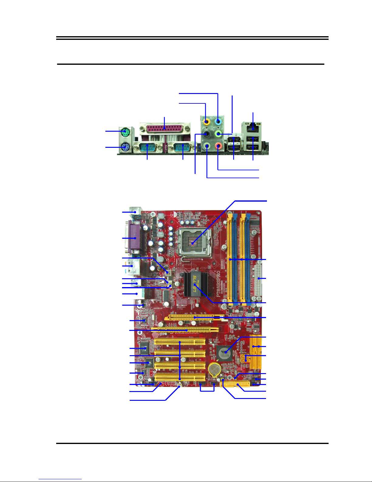
1-4 Layout Diagram & Jumper Setting
USB Port
(USB2, USB3)
PCI Slot
Front Panel Audio
ITE IT8705 I/O Chip
AC97’ Audio Codec
4MBit Flash ROM BIOS
USB Power On Jumper (JP3)
SFAN2
VIA VT6103 LAN PHY chip
PCI EXPRESSx16
Floppy Connector
VIA PT880PRO Chip
Front Panel Connector
ATA 133 IDE Connector
Clear CMOS (JBAT)
CPU Socket
DDR DIMM X4
VIA VT8237 Chip
Power LED/Speaker Connector
KB/MS/USB Power ON Jumper
(JP1)
USB Port/LAN Connector
PS2 KB/Mouse Port
USB Port
Audio Connector
SFAN1
PC99 Back Panel
ATX 12V Power Connector
CPU FAN
ATX Power Connector
Serial-ATA Connector
(SATA1, 2)
AGP 4X/8X Slot
CD Audio In
COM1
COM2
USB2
PS/2 Mouse
PS/2 Keyboard
PRINT
LAN
USB
Line-IN
Line-OUT
Surrback
MIC-IN
GEN/LFE
SURROUND
6
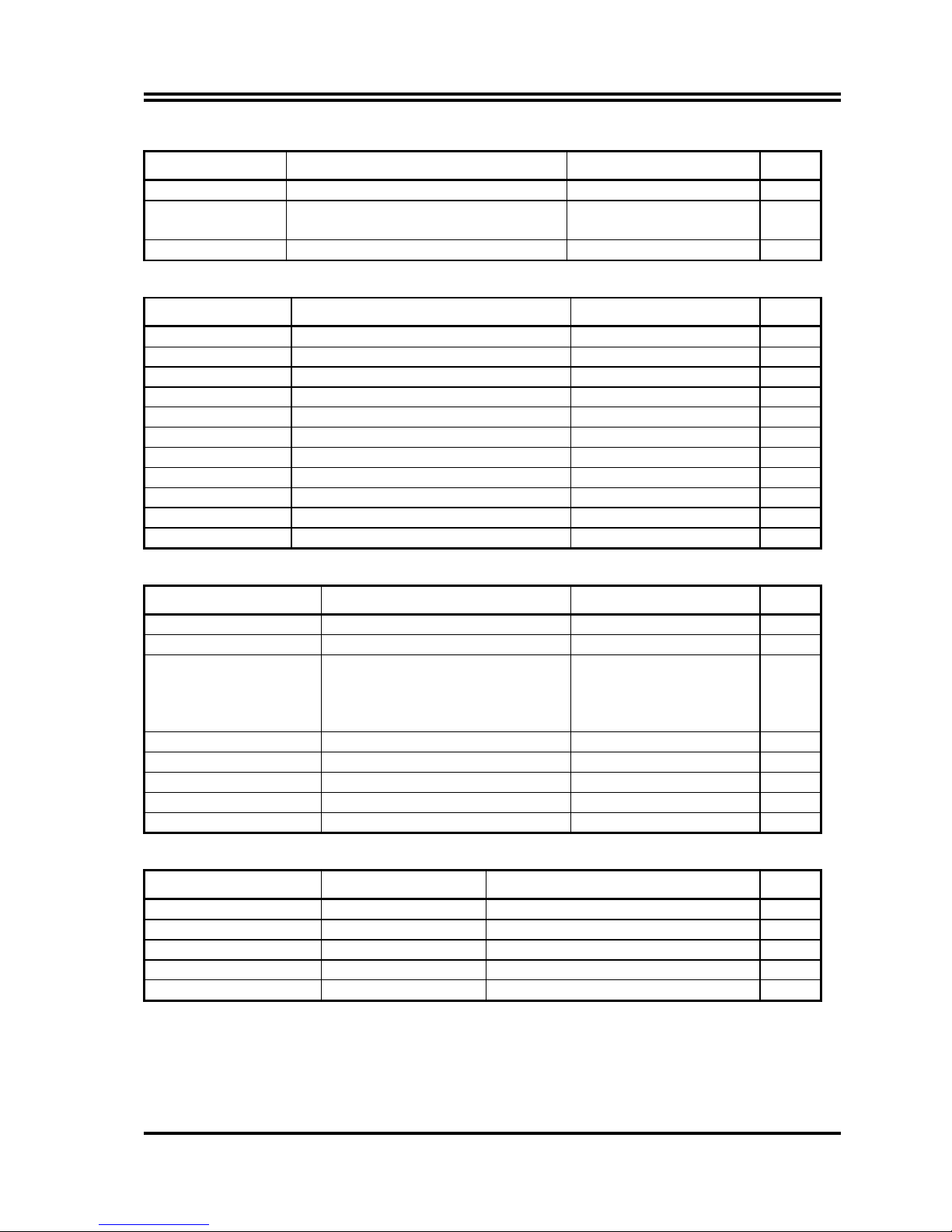
Jumpers
Jumper Name Description Page
JBAT CMOS RAM Clear 3-pin Block P.6
JP1 Keyboard/USB Power On
Enable/Disabled
3-pin Block P.7
JP3 USB Power On Enable/Disabled 3-pin Block P.7
Connectors
Connector Name Description Page
ATXPWR24P ATX Power Connector 24-pin Block P.23
ATX12V ATX 12V Power Connector 4-pin Block P.23
PS2KBMS1 PS/2 Mouse & PS/2 Keyboard Connector 6-pin Female P.24
PARALLEL Parallel Port Connector 25-pin Female P.24
USB, USB1 USB Port Connector 4-pin Connector P.24
LAN LAN Port Connector RJ-45 Connector P.24
COM1,COM2 Serial Port COM1,COM2 Connector 9-pin Male Connector P.24
CN1 (AUDIO) Audio Connector 6 phone jack P.24
FDD Floppy Driver Connector 34-pin Block P.24
IDE1/IDE2 Primary/Secondary IDE Connector 40-pin Block P.25
SATA1, SATA2 Serial ATA Port Connector 7-pin Block P.25
Headers
Header Name Description Page
AUDIO Line-Out, MIC Header 9-pin Block P.26
USB2/USB3 USB Port Headers 9-pin Block P.26
JW FP
(Power LED/Reset/
IDE LED/ Power Button)
Front Panel Header
(including Power LED/IDE activity
LED/Reset switch / Power On
Button lead)
9-pin Block P.26
SPEAK PC Speaker Connector 4-pin Block P.26
PWR LED Power LED 3-pin Block P.26
CPUFAN FAN Headers 4-pin Block P.27
SFAN1, SFAN2 FAN Headers 3-pin Block P.27
CDIN CD Audio-In Header 4-pin Block P.27
Expansion Sockets
Socket/Slot Name Description Page
LGA 775 Socket CPU Socket LGA775 CPU Socket P.8
DIMM1 ~ 4 DDR Module Socket 184-pin DDR Module expansion Socket P.18
PCI1 ∼ PCI4 PCI Slot 32-bit PCI Local Bus Expansion slots P.19
AGP AGP 8X Mode Slot AGP Expansion Slot P.22
PE1 PCI-Express x16 Slot PCI-Express x16 Expansion Slot P.22
7
Chapter 2
Hardware installation
2-1 Pre-Hardware installation
Before starting to use the computer with the motherboard installed the components on it, please
make sure complete the following steps:
1. To verify the jumper settings of your motherboard
2. To install the CPU and Cooling Kits
3. To install the system memory
4. To install the expansion cards
5. To connect with ribbon cables, panel wires, and power supply
6. To setup BIOS
7. To install software driver & utility
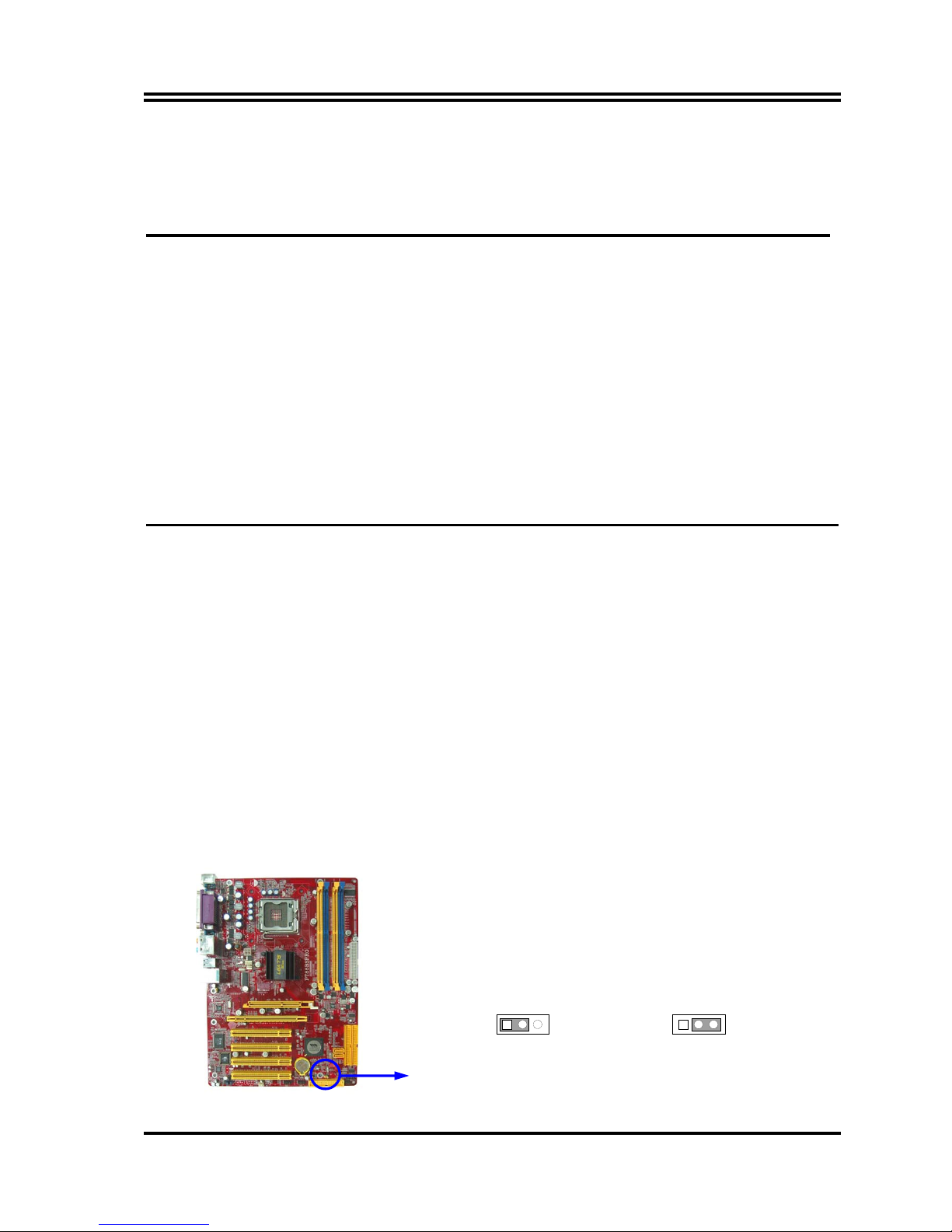
2-2 To verify the jumper settings of the motherboard
(1) CMOS RAM Clear (3-pin) : JBAT
A battery must be used to retain the motherboard configuration in CMOS RAM short 1-2
pins of JBAT to store the CMOS data.
To clear the CMOS, follow the procedure below:
1. Turn off the system and unplug the AC power
2. Remove ATX power cable from ATX power connector
3. Locate JBAT and short pins 2-3 for a few seconds
4. Return JBAT to its normal setting by shorting pins 1-2
5. Connect ATX power cable back to ATX power connector
Note: When should clear CMOS
1. Troubleshooting
2. Forget password
3. After over clocking system boot fail
CMOS RAM Clear Setting
JBAT
1 3
2-3 closed Clear CMOS
JBAT
1 3
1-2 closed Normal (Default)
8
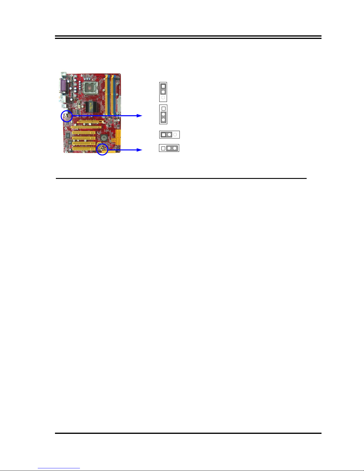
(2) Keyboard/USB Power On function Enabled/Disabled: JP1, JP3
When setting Enabled you can using keyboard by key in password/USB to power on system.
JP3 2-3 closed USB Power On Enabled
JP3 1-2 closed USB Power On Disabled (Default)
JP1 2-3 closed Keyboard/USB Power On Enabled
JP1 1-2 closed Keyboard/USB Power On Disabled (Default)
JP1
1
3
JP1
1
3
JP3
1 3
JP3
1 3
2-3 To install the CPU
2-3-1 Glossary
Chipset (or core logic) - two or more integrated circuits which control the interfaces between
the system processor, RAM, I/O devises, and adapter cards.
Processor socket - the socket used to mount the system processor on the motherboard.
Slot (AGP, PCI, ISA, RAM DIMMs) - the slots used to mount adapter cards and system RAM.
AGP - Accelerated Graphics Port - the high speed interface for video cards which runs at 1X
(66MHz), 2X (133MHz), 4X (266MHz), and 8X (533MHz).
PCI - Peripheral Component Interconnect - the high speed interface for video cards, sound cards,
network interface cards, and modems which runs at 33MHz.
PCI Express- Peripheral Component Interconnect Express- a high speed interface for video
cards, sound cards, network interface cards, and modems.
Serial Port - the low speed interface typically used for mouse and external modems.
Parallel Port - the low speed interface typically used for printers.
PS/2 - the low speed interface used for mouse and keyboards.
USB - Universal Serial Bus - the medium speed interface typically used for mouse, keyboards,
scanners, and some digital cameras.
Sound (interface) - the interface between the sound card or integrated sound connectors and
speakers, MIC, game controllers, and MIDI sound devices.
LAN (interface) - Local Area Network - the interface links to local area network.
BIOS (Basic Input/Output System) - the program logic used to boot up a computer and establish
the relationship between various components.
Driver - software, which defines the characteristics of a device for use by another device or
other software.
Processor - the "central processing unit" (CPU); the principal integrated circuit used for doing
the "computing" in "personal computer"
Front Side Bus Frequency -
the working frequency of the motherboard, which is generated by
the clock generator for CPU, DRAM and PCI BUS.
CPU L2 Cache -
the flash memory inside the CPU, normally Athlon serial CPU has 256K or
above, and Duron has 64K.
9
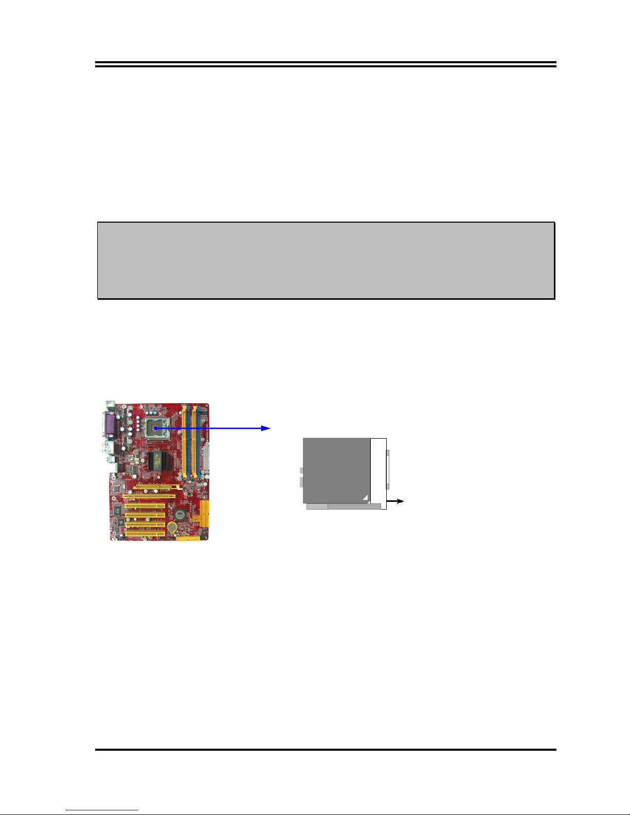
2-3-2 About INTEL PENTIUM 4 775PIN CPU
This motherboard provides a 775-pin surface mount, LGA775 Land Grid Array socket, referred to
as the LGA775 socket supports Intel Pentium 4 processor in the 775 Pin package utilizes
Flip-Chip Land Grid Array (FC-LGA4) package technology.
The CPU that comes with the motherboard should have a cooling FAN attached to prevent
overheating. If this is not the case, then purchase a correct cooling FAN before you turn on your
system.
WARNING!
Be sure that there is sufficient air circulation across the processor’s heatsink
and CPU cooling FAN is working correctly, otherwise it may cause the
processor and motherboard overheat and damage, you may install an auxiliary
cooling FAN, if necessary.
To install a CPU, first turn off your system and remove its cover. Locate the LGA775 socket
and open it by first pulling the level sideways away from the socket then upward to a 90-degree
angle. Insert the CPU with the correct orientation as shown below. The notched corner should
point toward the end of the level. Because the CPU has a corner pin for two
of
the four corners,
the CPU will only fit in the orientation as shown.
CPU LGA 775 Socket
Colden
LGA 775
When you put the CPU into the LGA775 socket. No force require to insert of the CPU, then
press the level to Locate position slightly without any extra force.
10
2-3-3 LGA 775 CPU Installation Guide
Socket Preparation
1. Opening the socket:
Note: Apply pressure to the corner with right hand thumb while opening/closing the load lever, otherwise
lever can bounce back like a “mouse trap” and WILL cause bent contacts (when loaded)
1. Disengage Load Lever by depressing down and out
on the hook to clear retention tab
2. Rotate Load Lever to fully open position at
approximately 135degrees
3. Rotate Load Plate to fully open position at
approximately 100degrees
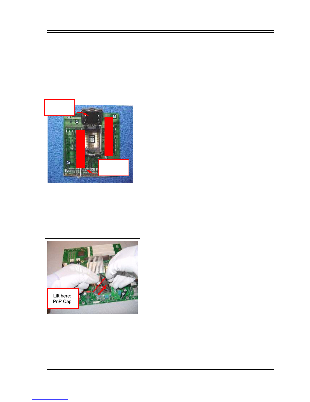
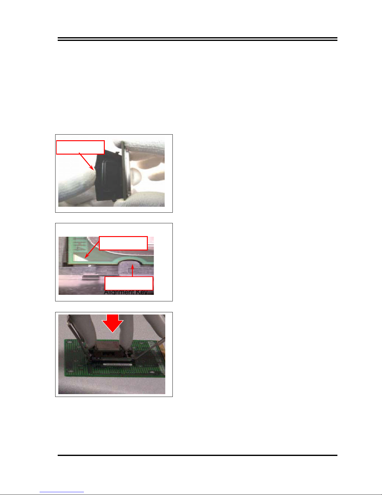
2. Remove PnP Cap (Pick & Place Cap)
i. With left hand index finger and thumb to support the load plate edge, engage PnP cap with right hand
thumb and peel the cap from LGA775 Socket while pressing on center of PnP cap to assist in removal.
ii. Set PnP cap aside. Always put PnP cap back on if the processor is removed from the socket.
iii. Visually inspect PnP cap for damage. If damage observed, replace the PnP cap.
Note: After PnP cap removal, make sure socket load plate
and contacts are free of foreign material; Refer to
Overview Module for FM cleaning.
Note: Optionally, remove PnP cap after CPU insertion. This
will compromise the ability to visually inspect socket.
Socket Load
Lever Open
Socket Load
Plate Open
11
3. Visually inspect for bent contacts (Recommend at least 1stpass visual inspection)
NOTE: Refer to the Handling and Inspection Module for 1stand 2ndpass inspection details.
NOTE: Glove images are for illustrative purposes only. Please consult local safety guidelines for specific
requirements
NOTE: Recommend not to hold the load plate as a lever, instead hold at tab with left hand, removing the
PnP cap with right hand
775-land LGA Package Insertion
1. Lift processor package from shipping media by grasping
the substrate edges ONLY.
Note: Orient processor package such that the Pin 1
triangle mark is on bottom left and both key notches
are on left side
2. Land Side Cover Handling: Remove land side cover with
the opposite hand by depressing larger retention tab
and peeling the cover away
3. Set and reserve the land side cover aside.
Note: Always keep the land side cover on the processor
when not in the socket.
4. Visually inspect the package gold pads: Scan the
processor package gold pad array for presence of
foreign material. Refer to Overview Module for FM
cleaning recommendations
5. Orient the package with IHS up. Locate Pin 1 and the
two orientation key notches
6. Carefully place the package into the socket body using a
purely vertical motion
CAUTION: Using Vacuum Pen for installation is not
recommended
7. Verify that package is within the socket body and
properly mated to the orient keys
8. Close the socket by
i. Rotating the Load Plate onto the package HIS
ii. While pressing down lightly on Load Plate, engage the
Load Lever.
iii. Securing Load Lever with Load Plate tab under
retention tab of Load Lever
Press to remove
Pin 1 Indicator
Alignment Key
12
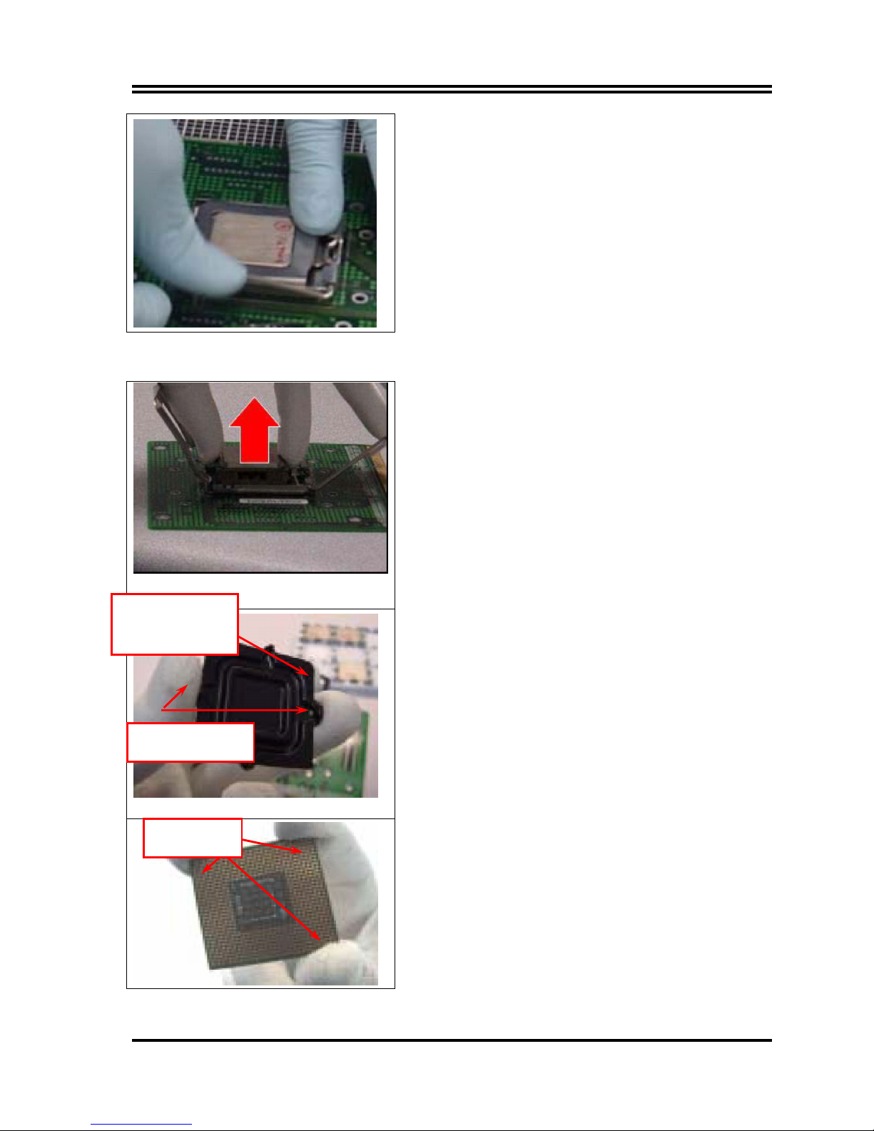
775-Land Package Removal
1. Open the Load Plate/Lever with both hands:
With left hand index finger and thumb to support the
load plate edge, engage PnP cap with right hand thumb
and peel the cap from LGA775 Socket while pressing
on center of PnP cap to assist in removal.
2. Pick up 775-land LGA package:
By Vacuum Pen: Place a minimum 9-mm cup at
approximately the center of IHS.
Recommend not to place Vacuum Pen on IHS edge. Risk of
dropping and causing bent contact.
Recommend not to use Vacuum Pen for inserting CPU By
Hand: Index finger to hold load plate hinge
side and thumb to hold load lever side
3. Lift the package straight up and away.
4. Assemble processors land side cover immediately to
prevent contamination.
i. While holding the processor by the 3 corners, the other
hand lift land side cover from work surface by grasping
at the large retention tabs. Ensure retention tabs and
package are pointing each other.
ii. Orientate so that land side cover chamfer is matching
with package Pin 1 location.
iii. Hook the first large retention tab on the package
substrate. Then press the opposite tab onto the
substrate.
iv. Place processor with land side cover installed onto
proper shipping media or other ESD approved work
surface
Chamfer on Land Side
Cover (align this with
pin 1 mark on 775-land
LGA package)
Large Retention Tabs
(pointing towards user)
Hold at corners
13
5. Visually inspect socket contact array
1. First Pass Inspection
i. Scan socket contact array at varying angles noting the presence of any foreign material
ii. If foreign material can’t be blown off by compressed air, or mechanical damage (Mode1 or 4) observed,
reject the motherboard for further evaluation or socket replacement.
2. Second Pass Inspection
i. Repeat 2 more times to sight down the rows and columns from each of the 4 sides of the socket to
ensure all contacts within the array are inspected
ii. Inspect for Mode2, Mode3, and Mode5 failures
Note: Refer to the Test Module for detail visual inspections
6. Assemble LGA775 socket PnP cap
i. Secure/Hook the back side of PnP cap.
ii. Snap down the front side to fully secure
7. Close the Socket
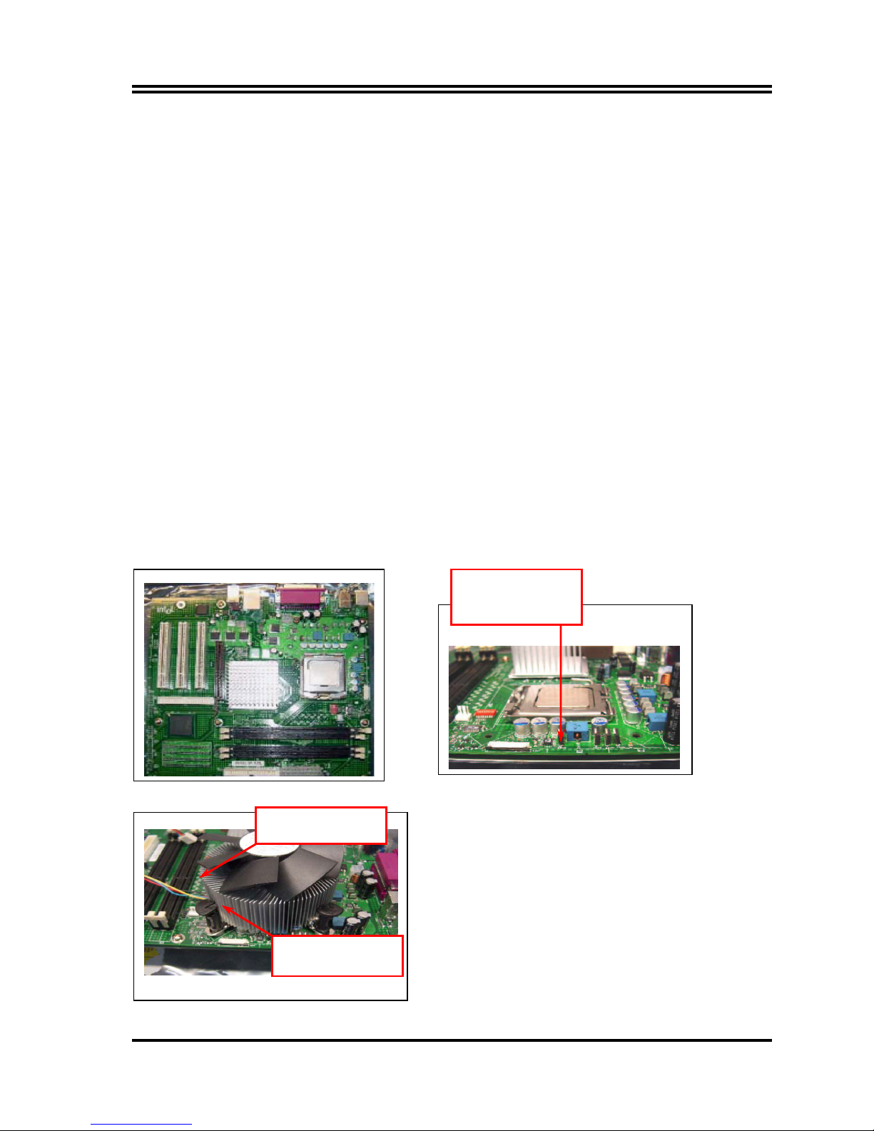
Intel Reference Thermal Solution Assembly
NOTE: Depending on the configuration, Thermal Solution Integration procedure could perform with M/B
alone or with M/B in the Chassis.
1. Place motherboard on support structure providing
minimum 0.150-inch backside clearance
2. Apply 300 mg of Thermal Interface Material (Shin- Etsu
G751) onto center of IHS
0.150-inch backside
clearance for fastener
Fan cabled on side
closest to MB header
Fastener slots
pointing straight out
14
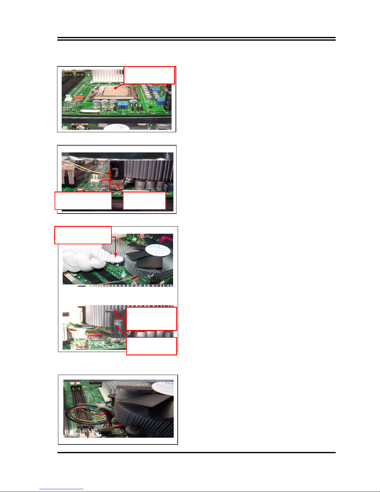
NOTE: Thermal Solutions that come with IntelR boxed
processor use pre-applied thermal interface material and
not grease.
3. Remove Heat Sink (HS) from packaging media
4. Place HS onto the LGA775 Socket
• Ensure fan cables are oriented on side closest to fan
header
• Align Fasteners with MB through-holes
5. Inspection
• Ensure cables are not trapped or interfere fastener
operation
• Ensure fastener slots are pointing straight out from
heatsink
6. Actuate fasteners
• While holding HS to prevent tilting, press down on
fastener caps with thumb to install and lock
Repeat with remaining fasteners
7. Inspection
• Verify the fasteners are properly seated
• Ensure both fastener cap and base are flush with
spring and motherboard
8. Connect fan header with Board header
9. Secure excess cable with tie-wrap to ensure cable
does not interfere with fan operation or contact other
components.
Apply Thermal
Interface Material
Fastener Cap not
resting against spring
Fastener flush
against MB
Press Down
(4 Places)
Both fastener
halves are flush
against spring
Fastener flush
against spring
 Loading...