

Page 1

P4XFA/P4MFA
USER'S MANUAL
M/B For Socket 478 Pentium 4 Processor
Trademark:
NO. G03-P4XFAR5A
Release date: July 2002
* Specifications and Information contained in this documentation are furnished for information use only, and are
subject to change at any time without notice, and should not be construed as a commitment by manufacturer.
Page 2

TABLE OF CONTENT
USER’S NOTICE................................................................................ ii
MANUAL REVISION INFORMATION..............................................1
COOLING SOLUTIONS ................................................................... 1
CHAPTER 1 INTRODUCTION
1-1 FEATURE OF MOTHERBOARD ............................................... 2
1-2 SPECIFICATION .................................................................... 3
1-3 PERFORMANCE LIST............................................................. 4
1-4 LAYOUT DIAGRAM & JUMPER SETTING ................................ 5
P4XFA/P4MFA MOTHERBOARD
OF
CHAPTER 2 HARDWARE INSTALLATION
2-1 HARDWARE INSTALLATION STEPS ........................................ 7
2-2 CHECKING MOTHERBOARD'S JUMPER SETTING.................... 7
2-3 INSTALL CPU ........................................................................ 8
2-3-1 GLOSSARY .................................................................. 8
2-3-2 ABOUT INTEL PENTIUM 4 478-PIN CPU.......................... 9
2-4 INSTALL MEMORY................................................................ 9
2-5 EXPANSION CARD ................................................................. 10
2-5-1 PROCEDURE FOR EXPANSION CARD INSTALLATION .............10
2-5-2 ASSIGNING IRQ FOR EXPANSION CARD.................................
2-5-3 INTERRUPT REQUEST TABLE FOR THIS MOTHERBOARD .......
2-5-4 AGP SLOT ............................................................................
2-6 CONNECTORS, HEADERS....................................................... 12
2-6-1 CONNECTORS ......................................................................
2-6-2 HEADERS .............................................................................15
2-7 STARTING UP YOUR COMPUTER ........................................... 18
11
11
11
12
CHAPTER 3 INTRODUCING BIOS
3-1 ENTERING SETUP.................................................................. 19
3-2 GETTING HELP ..................................................................... 19
3-3 THE MAIN MENU................................................................... 20
3-4 STANDARD CMOS FEATURES................................................. 21
3-5 ADVANCED BIOS FEATURES .................................................. 22
3-6 ADVANCED CHIPSET FEATURES ............................................ 24
3-6-1 DRAM TIMING SETTINGS............................................. 25
3-6-2 AGP FUNCTION SETTINGS ........................................... 26
3-6-3 PCI TIMING SETTINGS ................................................. 26
3-7 INTEGRATED PERIPHERALS.................................................. 26
3-7-1 ONCHIP IDE FUNCTION ............................................... 27
3-7-2 ONCHIP DEVICE FUNCTION ......................................... 28
3-7-3 ONCHIP SUPER IO FUNCTION ...................................... 29
3-8 POWER MANAGEMENT SETUP............................................... 30
3-8-1 PM WAKE UP EVENTS .................................................31
i
Page 3

3-8-1.1 IRQS ACTIVITIES....................................................... 31
3-9 PNP/PCI CONFIGURATION SETUP .......................................... 32
3-9-1 IRQ RESOURCES .........................................................33
3-10 PC HEALTH STATUS ............................................................. 33
3-11 MISCELLANEOUS CONTROL................................................. 34
3-12 LOAD STANDARD/OPTIMIZED DEFAULTS ............................. 35
3-13 SET SUPERVISOR/USER PASSWORD ...................................... 35
CHAPTER 4 DRIVER & FREE PROGRAM INSTALLATION
MAGIC INSTALL SUPPORTS WINDOWS 9X/ME/NT4.0/2000 .............. 36
4-1 VIA 4 IN 1
4-2 VGA
4-3 SOUND
4-4 PC-HEALTH
4-5 MAGIC BIOS
4-6 PC-CILLIN
4-7 HOW TO DISABLE ON-BOARD SOUND .................................... 45
4-8 HOW TO UPDATE BIOS .......................................................... 45
INSTALL VIA SERVICE PACK 4 IN 1 DRIVER
INSTALL VIA P4M266 VGA DRIVER
INSTALL ALC AUDIO CODEC DRIVER
WINBOND HARDWARE DOCTOR MONITORING SOFTWARE
........................................................................ 40
INSTALL BIOS LIVE UPDATE UTILITY
INSTALL PC-CILLIN2000 ANTI-VIRUS PROGRAM
................ 37
........................... 39
........................ 39
........................ 41
.......... 43
USER’S NOTICE
COPYRIGHT OF THIS MANUAL BELONGS TO THE MANUFACTURER. NO PART OF
THIS MANUAL, INCLUDING THE PRODUCTS AND SOFTWARE DESCRIBED IN IT
MAY BE REPRODUCED, TRANSMITTED OR TRANSLATED INTO ANY LANGUAGE IN
ANY FORM OR BY ANY MEANS WITHOUT WRITTEN PERMISSION OF THE
MANUFACTURER.
THIS MANUAL CONTAINS ALL INFORMATION REQUIRED TO USE P4XFA/P4MFA
MOTHER-BOARD AND WE DO ASSURE THIS MANUAL MEETS USER’S REQUIREMENT
BUT WILL CHANGE, CORRECT ANY TIME WITHOUT NOTICE. MANUFACTURER
PROVIDES THIS MANUAL “AS IS” WITHOUT WARRANTY OF ANY KIND, AND WILL
NOT BE LIABLE FOR ANY INDIRECT, SPECIAL, INCIDENTIAL OR CONSEQUENTIAL
DAMAGES (INCLUDING DAMANGES FOR LOSS OF PROFIT, LOSS OF BUSINESS, LOSS
OF USE OF DATA, INTERRUPTION OF BUSINESS AND THE LIKE).
PRODUCTS AND CORPORATE NAMES APPEARING IN THIS MANUAL MAY OR MAY
NOT BE REGISTERED TRADEMARKS OR COPYRIGHTS OF THEIR RESPECTIVE
COMPANIES, AND THEY ARE USED ONLY FOR IDENTIFICATION OR EXPLANATION
AND TO THE OWNER’S BENEFIT, WITHOUT INTENT TO INFRINGE.
ii
Page 4

Manual Revision Information
Reversion Revision History Date
5.0 Fifth Edition July 2002
Item Checklist
P4XFA/P4MFA motherboard
Cable for IDE/Floppy
Cable for VGA Connector (forP4MFA)
CD for motherboard utilities
□
Cable for USB Port 3/4(Option)
P4XFA/P4MFA User’s Manual
Intel Pentium 4 Processor Family
Cooling Solutions
As processor technology pushes to faster speeds and higher performance, thermal
management becomes increasingly crucial when building computer systems.
Maintaining the proper thermal environment is key to reliable, long-term system
operation. The overall goal in providing the proper thermal environment is keeping
the processor below its specified maximum case temperature. Heatsinks induce
improved processor heat dissipation through increased surface area and concentrated
airflow from attached fans. In addition, interface materials allow effective transfers
of heat from the processor to the heatsink. For optimum heat transfer, Intel
recommends the use of thermal grease and mounting clips to attach the heatsink to
the processor.
When selecting a thermal solution for your system, please refer to the website below
for collection of heatsinks evaluated and recommended by Intel for use with Intel
processors. Note, those heatsinks are recommended for maintaining the specified
Maximum T case requirement. In addition, this collection is not intended to be a
comprehensive listing of all heatsinks that support Intel processors.
For vendor list of heatsink and fan, please visit :
http://developer.intel.com/design/Pentium4/components/index
1
Page 5

Chapter 1
Introduction of P4XFA/P4MFA Motherboard
1-1 Feature of motherboard
The P4XFA/P4MFA motherboard is design for use Intel Pentium 4 Processor in 478 Pin
Package Processor with the VIA P4X266A/P4M266 Chipset delivers a high performance and
professional desktop platform solution. Which utilize the Socket 478 design and the memory
size expandable to 2.0GB.
These motherboards use the newest VIA P4X266A/P4M266 Chipset. Supports 533MHz
System Bus in data transfer rate for P4XFA, and 400MHz System Bus in data transfer rate
in P4MFA. The motherboard provided 100MHz/133MHz Memory clock frequency,
support PC133/PC100 SDRAM and DDR266/DDR200 DDR Module. The VIA VT8233A
V-Link LPC South Bridge offer ULTRA ATA 133 to provide speedier HDD throughout
that boosts overall system performance.
These motherboards also has an integrated AC’97 2.1 CODEC on board which is fully
compatible with Sound Blaster Pro that gives you the best sound quality and compatibility.
The P4MFA integrated High Performance & High Quality 3D Accelerator supports UltraAGPII with 2GB/s bandwidth, built-in MPEG-2/1 Video Decoder and Video Accelerator
supports VCD DVD HDTV decoding and playback, supports graphic and video overlay
function. Built-in programmable 24-bit true-color RAMDAC up to 250MHz pixel clock.
Programmable frame buffer size from 8MB and up to 64MB. For those wanting even greater
graphic performance, an AGP 4X slot is included on the board, support AGP 2X/4X
capability and Fast write Transaction.
With USB control as well as capability of expanding to 4 USB function ports delivering
2x12Mb/s bandwidth and rich connectivity, these motherboards meet future USB demand
also has built-in hardware monitor function to monitor and protect your computer.
A useful software tool “Magic BIOS” examines the BIOS version automatically with the
correct version available on the web, links the site for users to download the latest version
of BIOS and updates the BIOS. Use “Magic BIOS”, users can download and update BIOS
automatically and completed under the OS easily.
These motherboards provide high performance & meets future specification demand. It is
really wise choice for your computer.
2
Page 6

1-2 Specification
Spec Description
Design
Chipset
CPU Socket
(mPGA478B Socket)
Memory Socket
Expansion Slot &
Headers
Integrate IDE
VGA
(Only for P4MFA)
Audio
BIOS
Multi I/O
ATX form factor 4 layers PCB size: 30.5x21.0cm
∗
VIA P4X266A North Bridge Chipset for P4XFA
∗
VIA P4M266 North Bridge Chipset for P4MFA
VIA VT8233A South Bridge Chipset
∗
Support Intel Pentium 4 478 Pin package utilizes Flip-Chip
∗
Pin Grid Array (FC-PGA2) package processor
Support 1.5G∼2.2G 478 Pin Pentium 4 processor
∗
Reserves support for future Intel Pentium 4 processors
∗
168-pin SDR SDRAM module socket x1 and 184-pin DDR
∗
Module socket x 2
Support 1 pcs PC133/PC100 SDRAM Module expandable to
∗
1.0GB, or 2 pcs DDR266/DDR200 DDR Modules Expandable
to 2.0GB
AGP slot x1 support AGP 2.0 & 4X mode
∗
32-bit PCI slot x5
∗
CNR slot x1
∗
Two PCI IDE controllers support PCI Bus Mastering, ATA
∗
PIO/DMA and the ULTRA DMA 33/66/100/133 functions
that deliver the data transfer rate up to 133 MB/s
Integrated High Performance & High Quality 3D Accelerator
∗
Support Ultra-AGPII with 2GB/s bandwidth
∗
Built-in programmable 24-bit true-color RAMDAC up to
∗
250MHz pixel clock
Programmable frame buffer size from 8MB and up to 64MB.
∗
AC’97 Digital Audio controller integrated
∗
AC’97 Audio CODEC on board
∗
Audio driver and utility included
∗
Award 2MB Flash ROM
∗
PS/2 keyboard and PS/2 mouse connectors
∗
Floppy disk drive connector x1
∗
Parallel port x1
∗
Serial port x2
∗
USB connector x2
∗
USB headers x2 (connecting cable option)
∗
Audio connector (Line-in, Line-out , MIC & Game Port)
∗
3
Page 7

1-3 Performance List
The following performance data list is the testing result of some popular benchmark
testing programs. These data are just referred by users, and there is no responsibility
for different testing data values gotten by users (the different Hardware & Software
configuration will result in different benchmark testing results.)
Performance Test Report
CPU: Intel Pentium 4 1.9GHz mPGAB package
DRAM: 256MB DDR266 x1 (SAMSUNG K4H280838B-TCB0)
256MB SDRAM x1 (KINGMAX KSV684T4A1A-06)
VGA Expansion Card: NVDIA Geforce2 MX-400 64MB (1024x768xHi-color)
Hard Disk Driver: IBM DTLA-305040 (ATA-100)
BIOS: Award Optimal default
OS: Win 98SE
DDR266 PC133 SDRAM
3D Mark 2000 5432 5360
3D Mark 2001 2509 2479
3D Winbench 2000 104 102
Final Reality 9.99 9.06
Content Creation Winstone 2000 43.2 41.5
Content Creation Winstone 2001 50.3 49.5
Content Creation Winstone 2002 20.1 18.6
Business Winstone2001 44.1 42.8
Winbench 99:
CPU Mark 99 111 101
FPU Winmark 99 6610 6610
Business Disk Winmark99 7150 7090
Hi-end Disk Winmark99 18800 18500
Business Graphic Winmark 434 428
Hi-end Graphic Winmark 1260 1230
SYS Mark 2000/2001 : SISMark 2000/2001 Rating (Internet Content Creation /
Office Productivity)
SISMark 2000 208 (226/195) 200 (217/188)
SISMark 2001 150 (175/129) 142 (160/126)
SISOFT Sandra 2001 :
Dhrystone ALU MIPS 3626 3630
Whetstone FPU MFLOPS 1137/2371 1135/2368
Int ALU/RAM MB/S 1181 701
Float FPU/RAM MB/S 1183 701
Integer SSE2 IT/S 7547 7554
Floating-Point SSE2 IT/S 9352 9350
QUAKE3 DEMO1 FPS 169.1 146.7
DEMO2 FPS 169.7 146.1
4
Page 8
t
WCPUID System/CPU Clock 101/1918.93 101/1918.93
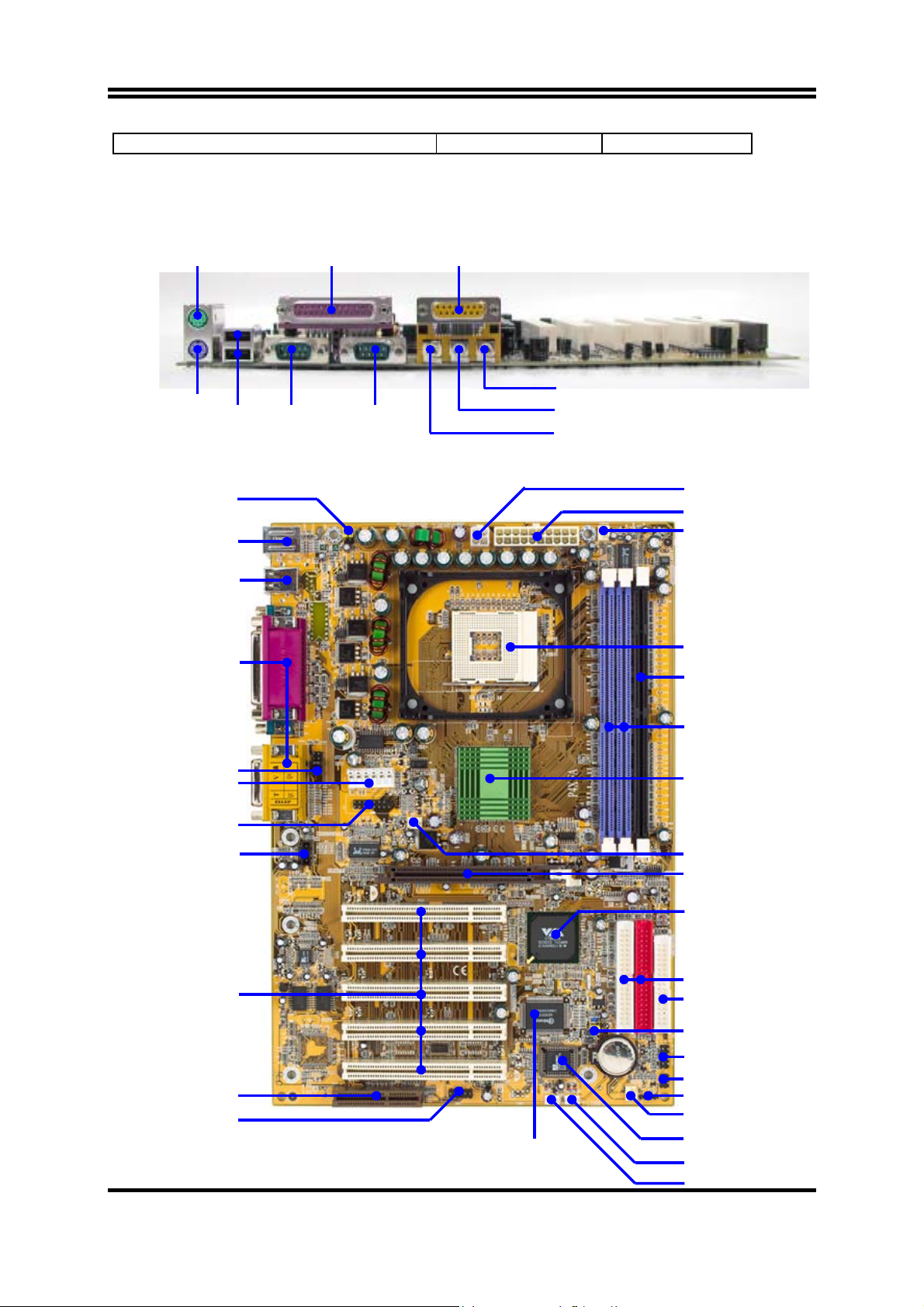
1-4 Layout Diagram & Jumper Setting
PS/2 MOUSE
PRINT GAME/MIDI PORT
PS/2
Keyboard
K/B Power ON Jumper (JP1)
PS2 KB/Mouse Port
USB Port
PC99 Back Panel
Front Panel Audio
ATX P6 Power
VGA Connector
(For P4MFA)
USB
COM1 COM2
MIC
LINE-IN
LINE-OUT
ATX 12V Power Conn.
ATX Power Conn.
CPU FAN
CPU Socket
SDR SDRAM DIMM x1
DDR SDRAM DIMM x2
VIA P4X266A Chip
VIA P4M266 Chip
CD Audio
PCI Slo
CNR Slot
USB1 Port
Winbond W83697HF Chip
5
System FAN
AGP Slot
VIA VT8233A Chip
ATA 133 IDE Conn.
Floppy Connector
Clear CMOS
Front Panel Connector
IR Connector
Speaker Conn.
System FAN1
2MBit Flash ROM BIOS
Wake On LAN
Wake On
(JBAT)
Page 9
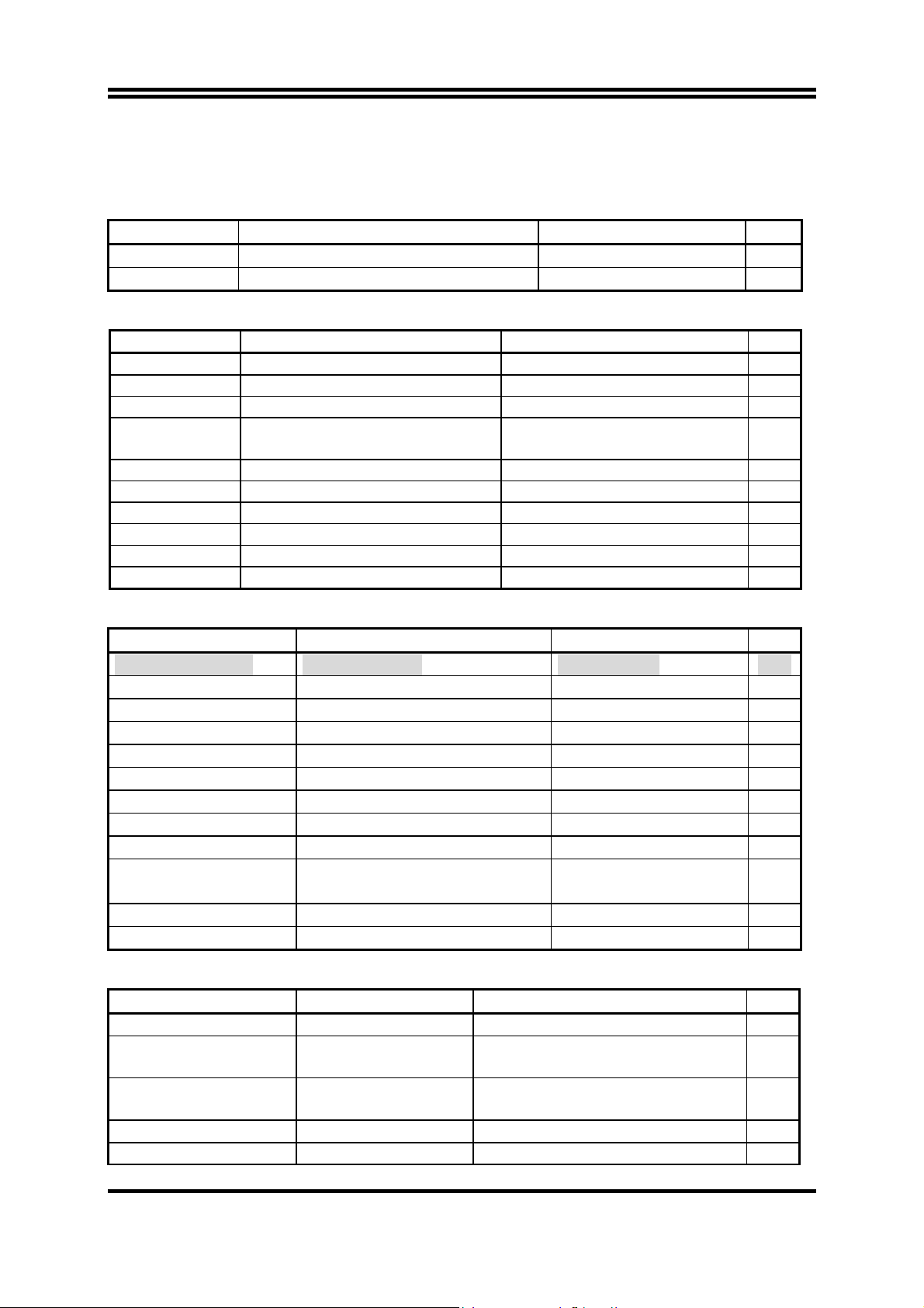
Jumpers
Jumper Name Description Page
JBAT CMOS RAM Clear 3-pin Block P.7
JP1 Keyboard Power On Enable/Disabled 3-pin Block P.7
Connectors
Connector Name Description Page
ATXPWR ATX Power Connector 20-pin Block P.12
ATX12V ATX 12V Power Connector 4-pin Block P.12
ATXP9 ATX P6 Power Connector 6-pin Block P.13
PS2KBM PS/2 Mouse & PS/2 Keyboard
6-pin Female P.13
Connector
CN1 USB Port Connector 4-pin Connector P.13
COM_LP Parallel Port Connector 25-pin Female P.13
AUDIO_GAME Audio/Game Connector 3 phone jack + 15-pin Connector P.13
COM1/COM2 Serial Port COM1/2 Connector 9-pin Connector P.13
FDD Floppy Driver Connector 34-pin Block P.14
IDE1/IDE2 Primary/Secondary IDE Connector 40-pin Block P.14
Headers
Header Name Description Page
VGA (for P4MFA) VGA Connector 2x8-pin Block P.15
AUDIO SPEAKER, MIC header 9-pin Block P.15
USB1 USB Port Headers 9-pin Block P.15
HD-LED IDE activity LED 2-pin Block P.16
RESET Reset switch lead 2-pin Block P.16
SPEAK PC Speaker connector 4-pin Block P.16
PWR-LED
PWR-BTN Power switch 2-pin Block P.16
WOL/WOM Wake On-LAN/Modem Headers 3-pin Block P.16
SFAN1, SYSFAN,
CPUFAN
IR IR infrared module Headers 5-pin Block P.17
CD_IN CD Audio-In Headers 4-pin Block P.17
Power LED 2-pin Block P.16
FAN Headers 3-pin Block P.17
Expansion Sockets
Socket/Slot Name Description Page
ZIF Socket 478 Pin CPU Socket 478-pin mPGA CPU Socket P.9
SDR1 SDRAM Module
Socket
DDR1, DDR2 DDR Module Socket 184-pin DDR Module expansion
168-pin SDR SDRAM Module
Expansion Socket
P.9
P.9
Socket
PCI1 ∼ PCI5
PCI Slot 32-bit PCI Local Bus Expansion slots P.10
AGP AGP 4X Mode Slot AGP Expansion Slot P.11
6
Page 10
CNR CNR Slot Communication Network Riser Slot
Chapter 2
Hardware installation
2-1 Hardware installation Steps
Before using your computer, you had better complete the following steps:
1. Check motherboard jumper setting
2. Install CPU and Fan
3. Install System Memory (DIMM)
4. Install Expansion cards
5. Connect IDE and Floppy cables, Front Panel /Back Panel cable
6. Connect ATX Power cable
7. Power-On and Load Standard Default
8. Reboot
9. Install Operating System
10. Install Driver and Utility
2-2 Checking Motherboard’s Jumper Setting
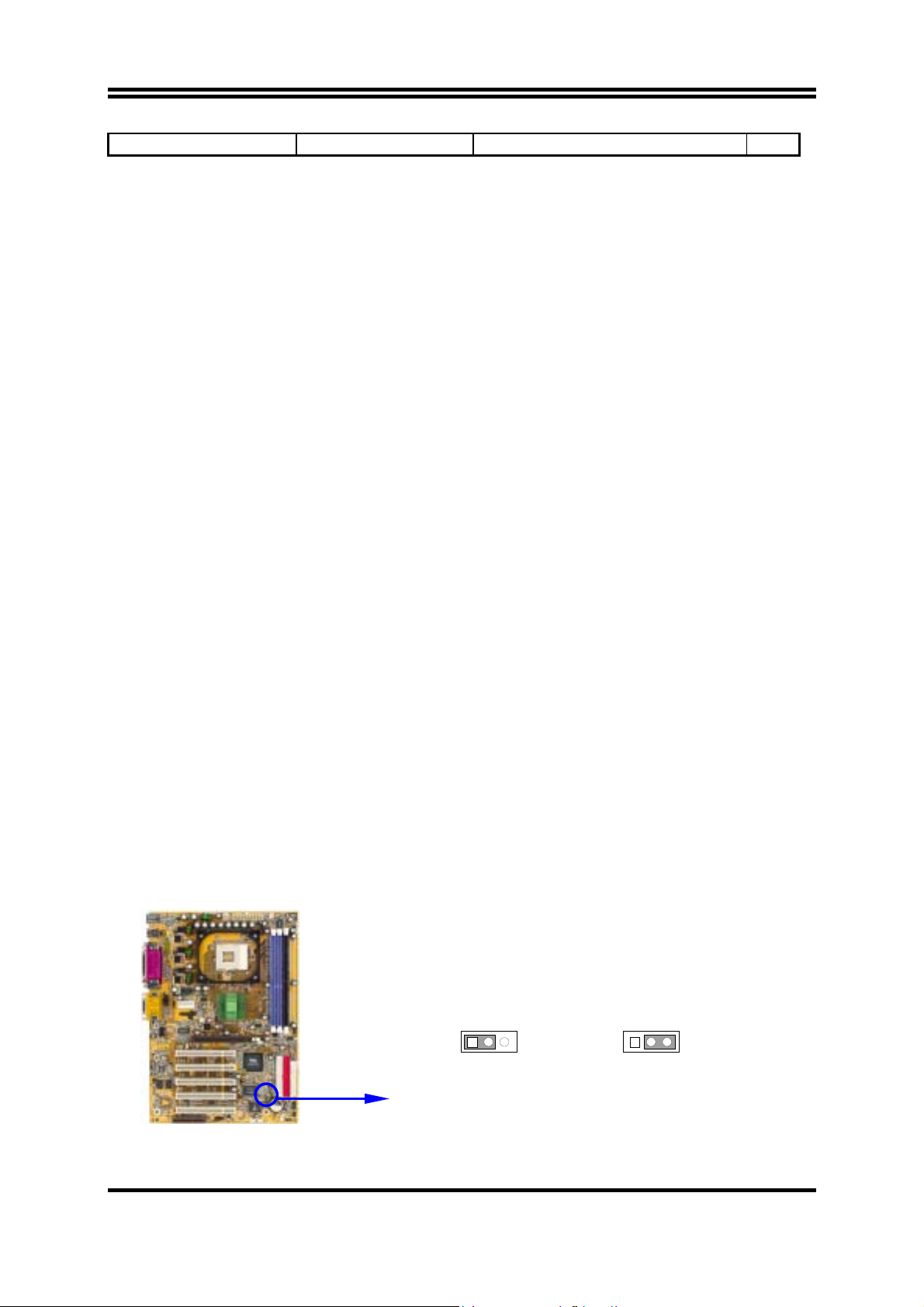
(1) CMOS RAM Clear (3-pin) : JBAT
A battery must be used to retain the motherboard configuration in CMOS RAM short
1-2 pins of JBAT to store the CMOS data.
To clear the CMOS, follow the procedure below:
1. Turn off the system and unplug the AC power
2. Remove ATX power cable from ATX power connector
3. Locate JBAT and short pins 2-3 for a few seconds
4. Return JBAT to its normal setting by shorting pins 1-2
5. Connect ATX power cable back to ATX power connector
Note: When should clear CMOS
1. Troubleshooting
2. Forget password
3. After over clocking system boot fail
JBAT
1 3
1-2 closed Normal
CMOS RAM Clear Setting
(2) Keyboard Power On function Enabled/Disabled: JP1
7
JBAT
1 3
2-3 closed Clear CMOS
Page 11
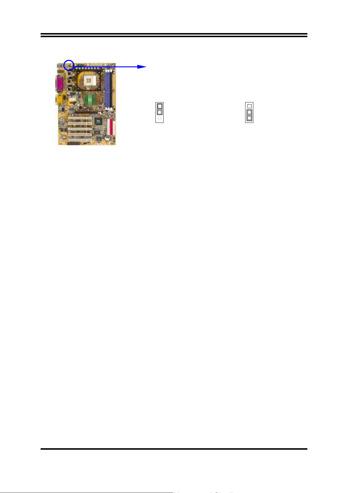
When setting Enabled you can using keyboard by key in password to power on system.
JP1
1
3
(Default)
JP1
1
3
2-3 closed K/B Power ON Enabled 1-2 closed K/B Power ON Disable
Keyboard Power On Setting
2-3 Install CPU
2-3-1 Glossary
Chipset (or core logic) - two or more integrated circuits which control the interfaces
between the system processor, RAM, I/O devises, and adapter cards.
Processor slot/socket - the slot or socket used to mount the system processor on the
motherboard.
Slot (AGP, PCI, ISA, RAM) - the slots used to mount adapter cards and system RAM.
AGP - Accelerated Graphics Port - a high speed interface for video cards; runs at 1X
(66MHz), 2X (133MHz), or 4X (266MHz).
PCI - Peripheral Component Interconnect - a high speed interface for video cards, sound
cards, network interface cards, and modems; runs at 33MHz.
ISA - Industry Standard Architecture - a relatively low speed interface primarily used for
sound cards and modems; runs at approx. 8MHz.
Serial Port - a low speed interface typically used for mouse and external modems.
Parallel Port - a low speed interface typically used for printers.
PS/2 - a low speed interface used for mouse and keyboards.
USB - Universal Serial Bus - a medium speed interface typically used for mouse, keyboards,
scanners, and some digital cameras.
Sound (interface) - the interface between the sound card or integrated sound connectors and
speakers, MIC, game controllers, and MIDI sound devices.
LAN (interface) - Local Area Network - the interface to your local area network.
BIOS (Basic Input/Output System) - the program logic used to boot up a computer and
establish the relationship between the various components.
Driver - software, which defines the characteristics of a device for use by another device or
other software.
Processor - the "central processing unit" (CPU); the principal integrated circuit used for
doing the "computing" in "personal computer"
8
Page 12
Front Side Bus Frequency - the working frequency of the motherboard, which is generated
by the clock generator for CPU, DRAM and PCI BUS.
CPU L2 Cache - the flash memory inside the CPU, normal it depend on CPU type.
2-3-2 About Intel Pentium 4 478-pin CPU
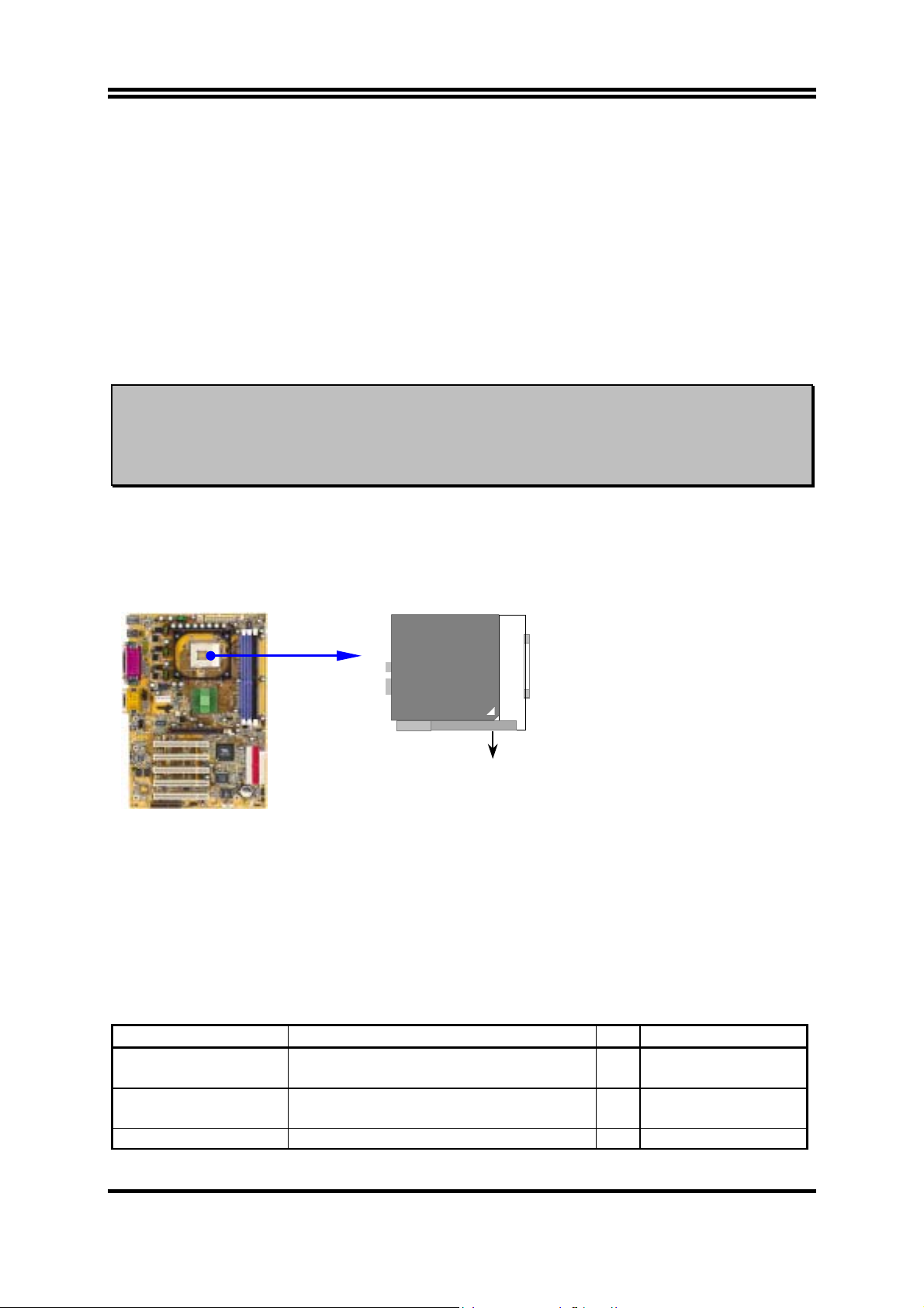
This motherboard provides a 478-pin surface mount, Zero Insertion Force (ZIF) socket,
referred to as the mPGA478B socket supports Intel Pentium 4 processor in the 478 Pin
package utilizes Flip-Chip Pin Grid Array (FC-PGA2) package technology.
The CPU that comes with the motherboard should have a cooling FAN attached to prevent
overheating. If this is not the case, then purchase a correct cooling FAN before you turn on
your system.
WARNING! Be sure that there is sufficient air circulation across the processor’s
heatsink and CPU cooling FAN is working correctly, otherwise it may
cause the processor and motherboard overheat and damage, you may
install an auxiliary cooling FAN, if necessary.
To install a CPU, first turn off your system and remove its cover. Locate the ZIF socket
and open it by first pulling the level sideways away from the socket then upward to a 90degree angle. Insert the CPU with the correct orientation as shown below. The notched
corner should point toward the end of the level. Because the CPU has a corner pin for two
of the four corners, the CPU will only fit in the orientation as shown.
CPU ZIF mPGAB Socket
mPGA478B
Colden Arrow
When you put the CPU into the ZIF socket. No force require to insert of the CPU, then
press the level to Locate position slightly without any extra force.
2-4 Install Memory
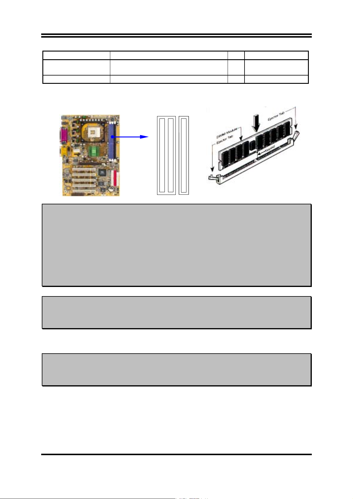
This motherboard provides two 184-pin DDR DUAL INLINE MEMORY MODULES
(DIMM) sites for DDR memory expansion available from minimum memory size of 64MB
to maximum memory size of 2.0GB SDR SDRAM, or one 168-pin SDR DIMM sites for
SDRAM memory for maximum memory size of 1.0GB.
Valid Memory Configurations
Bank 184-pin DDR DIMM Total Memory
Bank 0, 1 (DDR1) DDR266/DDR200
DDR DRAM Module
Bank 2, 3 (DDR2) DDR266/DDR200
DDR DRAM Module
Total System Memory (Max. 2.0GB) X2 64MB∼2.0GB
X1 64MB∼1.0GB
X1 64MB∼1.0GB
9
Page 13
Bank 168-pin SDR DIMM Total Memory
Bank 0, 1 (SDR1) PC133/PC100
X1 64MB∼1.0GB
SDR DRAM Module
Total System Memory (Max. 1.0GB) X1 64MB∼1.0GB
Generally, installing SDR/DDR SDRAM modules to your motherboard is very easy, you
can refer to figure 2-4 to see what a 168-pin SDR/184-pin DDR SDRAM module looks
like.
DDR2 (BANK2+BANK3)
DDR1 (BANK0+BANK1)
SDR1 (BANK0+BANK1)
Figure 2-4
NOTE! When you install DIMM module fully into the DIMM socket the eject tab
should be locked into the DIMM module very firmly and fit into its
indention on both sides.
WARNING! For the SDR SDRAM CLOCK is set at 133MHz, use only PC133/
DDR266-compliant SDR/DDR Modules. When this motherboard operate
at 133Mhz, most system will not even boot if non-compliant modules are
used because of the strict timing issues, if your SDR/DDR Modules are
not PC133/DDR266-compliant, set the SDRAM clock to 100MHz to
ensure system stability.
NOTE! It is only can install either SDRAM or DDR Module at one time. Don’t
install both DDR Module and SDR Module at same time, it will have risk
to damage your Memory and Motherboard.
2-5 Expansion Cards
WARNING! Turn off your power when adding or removing expansion cards or other
system components. Failure to do so may cause severe damage to both
your motherboard and expansion cards.
2
-5-1 Procedure For Expansion Card Installation
1. Read the documentation for your expansion card and make any necessary hardware or
software setting for your expansion card such as jumpers.
2. Remove your computer’s cover and the bracket plate on the slot you intend to use.
3. Align the card’s connectors and press firmly.
10
Page 14
4. Secure the card on the slot with the screen you remove above.
5. Replace the computer system’s cover.
6. Set up the BIOS if necessary.
7. Install the necessary software driver for your expansion card.
2-5-2 Assigning IRQs For Expansion Card
Some expansion cards need an IRQ to operate. Generally, an IRQ must exclusively assign
to one use. In a standard design, there are 16 IRQs available but most of them are already
in use.
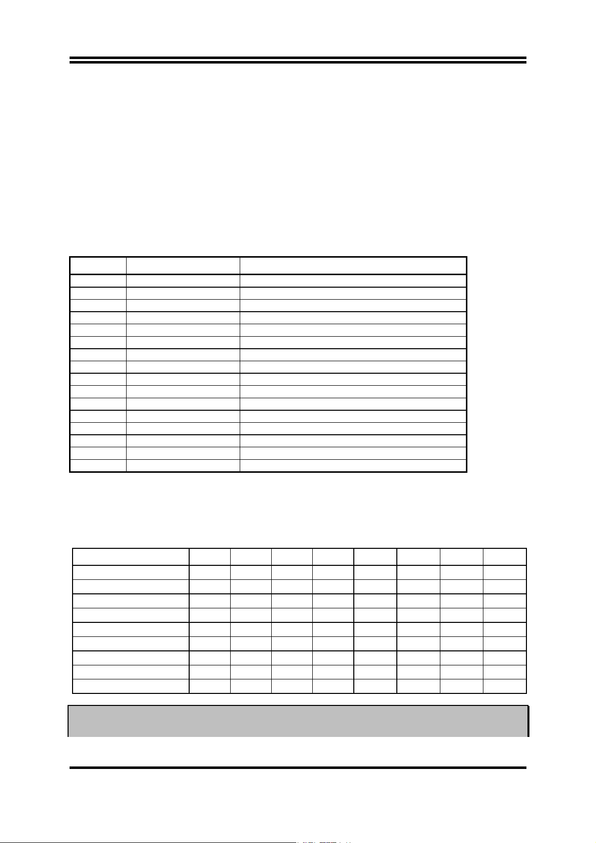
Standard Interrupt Assignments
IRQ Priority Standard function
0 N/A System Timer
1 N/A Keyboard Controller
2 N/A Programmable Interrupt
3 * 8 Communications Port (COM2)
4 * 9 Communications Port (COM1)
5 * 6 Sound Card (sometimes LPT2)
6 * 11 Floppy Disk Controller
7 * 7 Printer Port (LPT1)
8 N/A System CMOS/Real Time Clock
9 * 10 ACPI Mode when enabled
10 * 3 IRQ Holder for PCI Steering
11 * 2 IRQ Holder for PCI Steering
12 * 4 PS/2 Compatible Mouse Port
13 N/A Numeric Data Processor
14 * 5 Primary IDE Channel
15 * 1 Secondary IDE Channel
* These IRQs are usually available for ISA or PCI devices.
2-5-3 Interrupt Request Table For This Motherboard
Interrupt request are shared as shown the table below:
INT A INT B INT C INT D INT E INT F INT G INT H
Slot 1
Slot 2
Slot 3
Slot4
Slot5
Onboard USB 1
Onboard USB 2
AC97/MC97
LAN
IMPORTANT!
If using PCI cards on shared slots, make sure that the drivers support
√
“Shared IRQ” or that the cards don’t need IRQ assignments. Conflicts
√
√
√
√
√
√
√
√
11
Page 15
will arise between the two PCI groups that will make the system
unstable or cards inoperable.
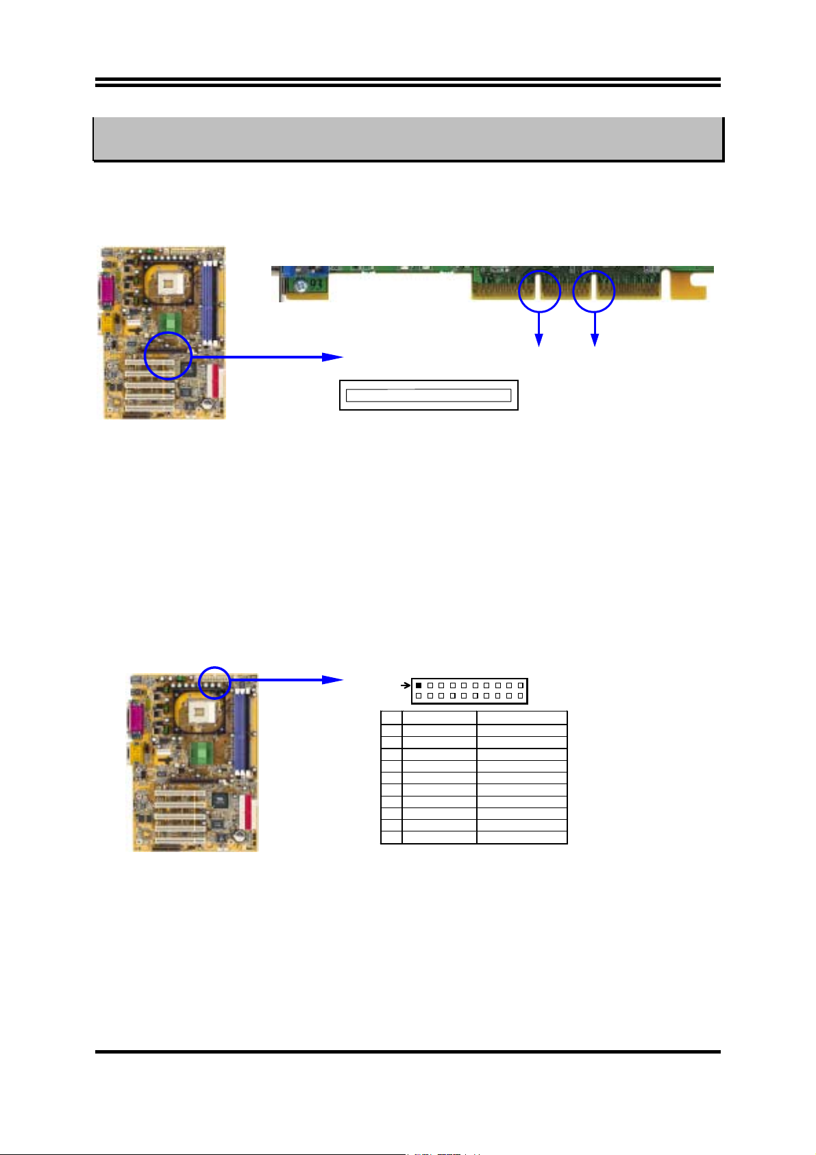
2-5-4 AGP Slot
This motherboard provides an AGP Slot, support the 2X/4X AGP VGA card.
2x notch 4x notch
AGP SLOT
2-6 Connectors, Headers
2-6-1 Connectors
(1) Power Connector (20-pin block) : ATXPWR
ATX Power Supply connector. This is a new defined 20-pins connector that usually
comes with ATX case. The ATX Power Supply allows to use soft power on
momentary switch that connect from the front panel switch to 2-pins Power On
jumper pole on the motherboard. When the power switch on the back of the ATX
power supply turned on, the full power will not come into the system board until the
front panel switch is momentarily pressed. Press this switch again will turn off the
power to the system board.
1 3.3V 3.3V
2 -12V 3.3V
3 GND GND
4 Soft Power On 5V
5 GND GND
6 GND 5V
7 GND GND
8 -5V Power OK
9 +5V +5V (for Soft Logic)
10 +5V +12V
Pin 1
PIN ROW2 ROW1
(2) ATX 12V Power Connector (4-pin block) : ATX12V
This is a new defined 4-pins connector that usually comes with ATX Power Supply.
The ATX Power Supply which fully support Pentium 4 processor must including this
connector for support extra 12V voltage to maintain system power consumption.
Without this connector might cause system unstable because the power supply can not
provide sufficient current for system.
12
Page 16
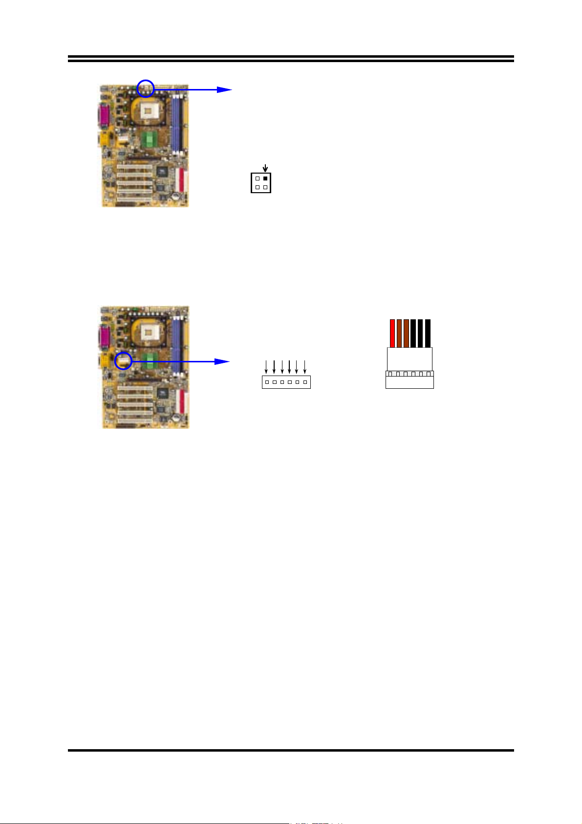
Pin 1
(3) ATX P6 Power Connector (6-pin block) : ATXP9
This is a new defined 6-pins connector that usually comes with ATX Power Supply.
The ATX Power Supply which fully support Pentium 4 processor must including this
connector for support extra 3.3V and 5V voltage to maintain system power
consumption. Without this connector might cause system unstable because the power
supply can not provide sufficient current for system.
5V
3.3V 3.3V
GND GND GND
RED
Power Plugs from Power Supply Power Connector on Motherboard
BLK
BLK
BLK
ORG
ORG
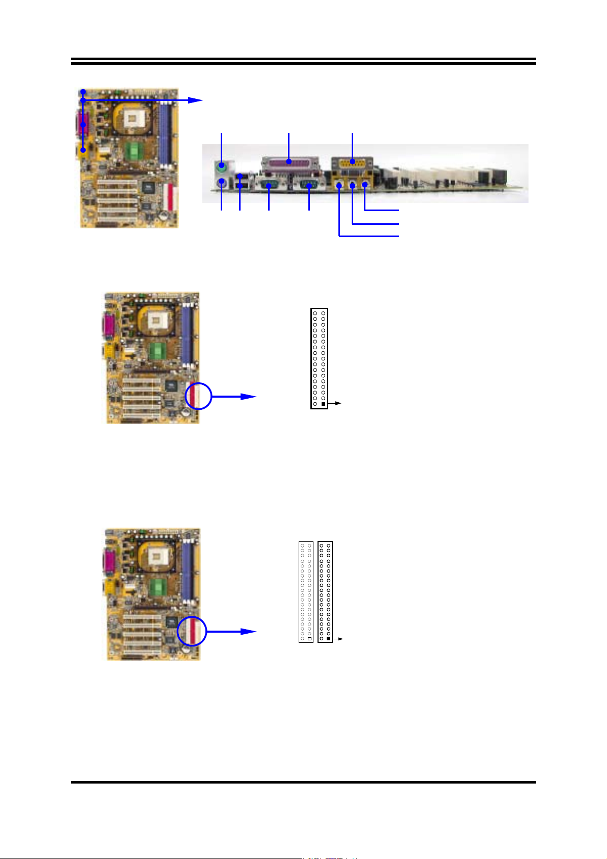
(4) PS/2 Mouse & PS/2 Keyboard Connector: PS2KBM
The connectors for PS/2 keyboard and PS/2 Mouse.
(5) USB Port connector: CN1
The connectors are 4-pin connector that connect USB devices to the system board.
(6) Parallel Port Connector (25-pin female): COM_LP
Parallel Port connector is a 25-pin D-Subminiature Receptacle connector. The Onboard Parallel Port can be disabled through the BIOS SETUP. Please refer to Chapter
3 “INTEGRATED PERIPHERALS SETUP” section for more detail information.
(7) Audio and Game Connector : AUDIO_GAME
This Connector are 3 phone Jack for LINE-OUT, LINE-IN, MIC and a 15-pin
D-Subminiature Receptacle Connector for joystick/MIDI Device.
Line-out : Audio output to speaker
Line-in : Audio input to sound chip
MIC : Microphone Connector
Game/MIDI : For joystick or MIDI Device
(8) Serial Port COM1, COM2 : COM1, COM2
COM1, COM2 are the 9-pin D-Subminiature mail connector. The On-board serial
port can be disabled through BIOS SETUP. Please refer to Chapter 3 “INTEGRATED
PERIPHERALS SETUP” section for more detail information.
13
Page 17
PS/2 MOUSE
PRINT GAME/MIDI PORT
MIC
COM1 COM2
PS/2
Keyboard
(9) Floppy drive Connector (34-pin block): FDD
USB
LINE-IN
LINE-OUT
This connector supports the provided floppy drive ribbon cable. After connecting the
single plug end to motherboard, connect the two plugs at other end to the floppy
drives.
Pin 1
Floppy Drive Connector
(10) Primary IDE Connector (40-pin block): IDE1
This connector supports the provided IDE hard disk ribbon cable. After connecting
the single plug end to motherboard, connect the two plugs at other end to your hard
disk(s). If you install two hard disks, you must configure the second drive to Slave
mode by setting its jumpers accordingly. Please refer to the documentation of your
hard disk for the jumper settings.
Pin 1
Primary IDE Connector
(11) Secondary IDE Connector (40-pin block): IDE2
This connector connects to the next set of Master and Slave hard disks. Follow the
same procedure described for the primary IDE connector. You may also configure
two hard disks to be both Masters using one ribbon cable on the primary IDE
connector and another ribbon cable on the secondary IDE connector.
14
Page 18
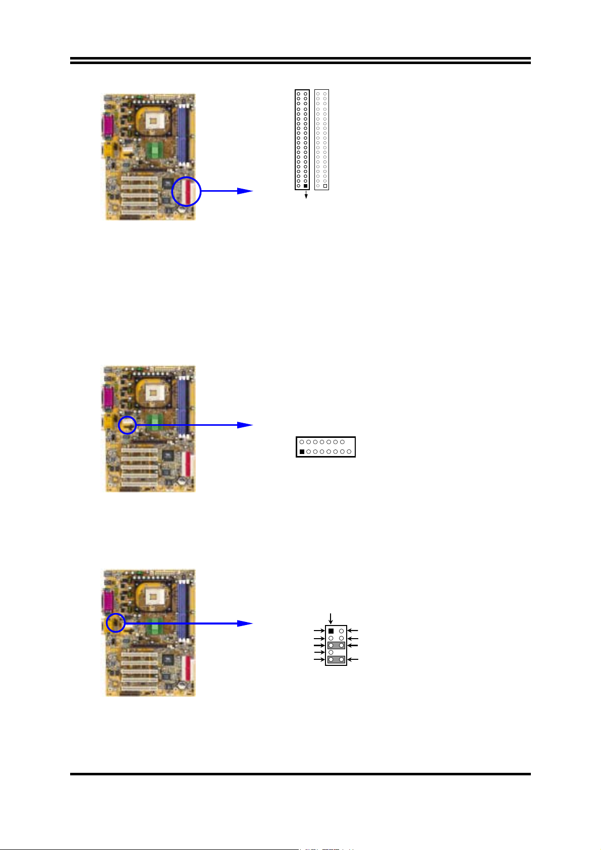
Two hard disks can be connected to each connector. The first HDD is referred to as
•
Pin 1
Secondary IDE Connector
the “Master” and the second HDD is referred to as the “Slave”.
For performance issues, we strongly suggest you don’t install a CD-ROM or DVD-
•
ROM drive on the same IDE channel as a hard disk. Otherwise, the system performance
on this channel may drop.
2-6-2 Headers
(1) VGA Connector (2x 8-pin) : VGA (for P4MFA)
2
VGA
1
VGA Connector
(2) Line-Out/MIC Header for Front Panel (9-pin): AUDIO
This header connect to Front Panel Line-out, MIC connector with cable.
Without install the cable, this header default setting is 5-6 short, 9-10 short. When
you install the cable you have take off these jumpers.
AUDIO
AUD_MIC
AUD_MIC_BIAS
AUD_FPOUT_R
HP_ON
AUD_FPOUT_L
Pin 1
9 10
2
16
15
AUD_GND
AUD_VCC
AUD_RET_R
AUD_RET_L
Line-Out, MIC Headers
(3) USB Port Headers (9-pin) : USB1
15
Page 19
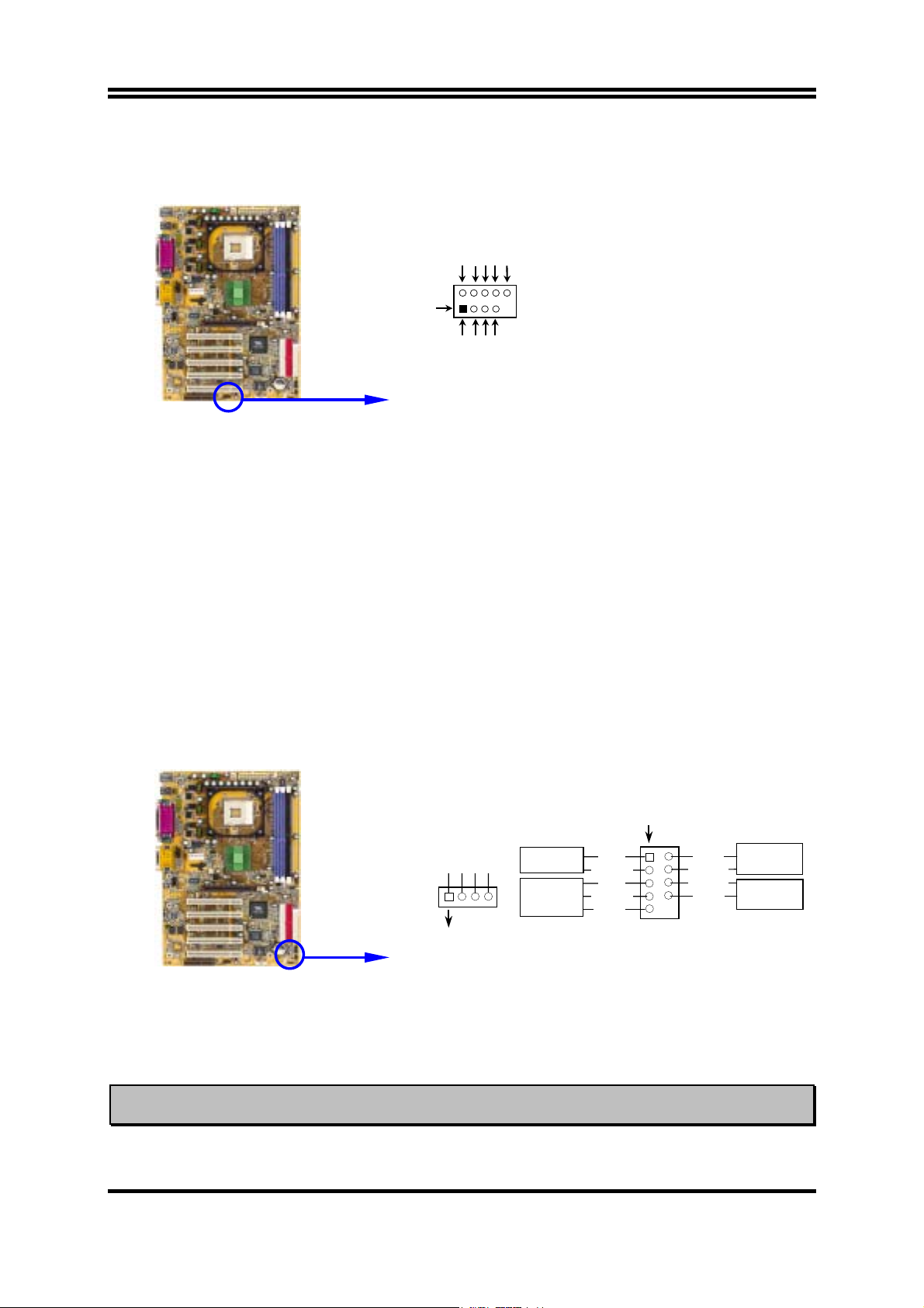
These headers are used for connecting the additional USB port plug. By attaching an
option USB cable, your can be provided with two additional USB plugs affixed to the
back panel.
OC
VCC
GND
DATA
-
+DATA
VCC
GND
DATA
-
+DATA
USB1
Pin 1
USB Port Headers
(4) IDE Activity LED: HD-LED
This connector connects to the hard disk activity indicator light on the case.
(5) Reset switch lead: RESET
This 2-pin connector connects to the case-mounted reset switch for rebooting your
computer without having to turn off your power switch. This is a preferred method
of rebooting in order to prolong the lift of the system’s power supply. See the figure
below.
(6)
Speaker connector: SPEAK
This 4-pin connector connects to the case-mounted speaker. See the figure below.
(7) Power LED
: PWR-LED
The Power LED is light on while the system power is on. Connect the Power LED
from the system case to this pin.
(8) Power switch
: PWR-BTN
This 2-pin connector connects to the case-mounted power switch to power ON/OFF the
system.
(9) Wake On-LAN/Modem Headers
VCC5
HDDLED
GND
RSTSW
NC
Pin 1
VCC5
ACPILED
PWRBTN
GND
GND
SPKR
NC
VCC5
SPEAK
Pin 1
System Case Connections
(3-pin) : WOM, WOL
JW_FP1
HDLED
RESET
This connector connects to a LAN/Modem card with a WAKE ON-LAN/Modem
output. This connector power up the system when a wake up signal is received through
the LAN/Modem card.
NOTE: This feature requires that Wake On LAN or Ring In Wake up is enabled.
PWR-LED
PWR-BTN
16
Page 20
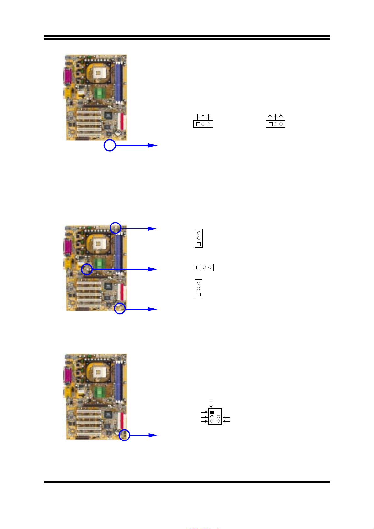
5VSB
GND
WOL
WOL
1 3
Wake-On-LAN Headers
WOM
5VSB
GND
WOM
Wake-On-Modem Headers
(10) FAN Headers (3-pin) : SFAN1, SYSFAN, CPUFAN
These connectors support cooling fans of 350mA (4.2 Watts) or less, depending on the
fan manufacturer, the wire and plug may be different. The red wire should be positive,
while the black should be ground. Connect the fan’s plug to the board taking into
consideration the polarity of connector.
CPUFAN
SYSFAN
SFAN1
3
1
3
1
3
1
FAN Speed Headers
(11) IR infrared module Headers (5-pin) : IR
This connector supports the optional wireless transmitting and receiving infrared
module. You must configure the setting through the BIOS setup to use the IR function.
Pin 1
IR
NC
VCC5
IRTX
2
GND
IRRX
5 6
IR infrared module Headers
(12) CD Audio-In Headers (4-pin) : CD_IN
17
Page 21
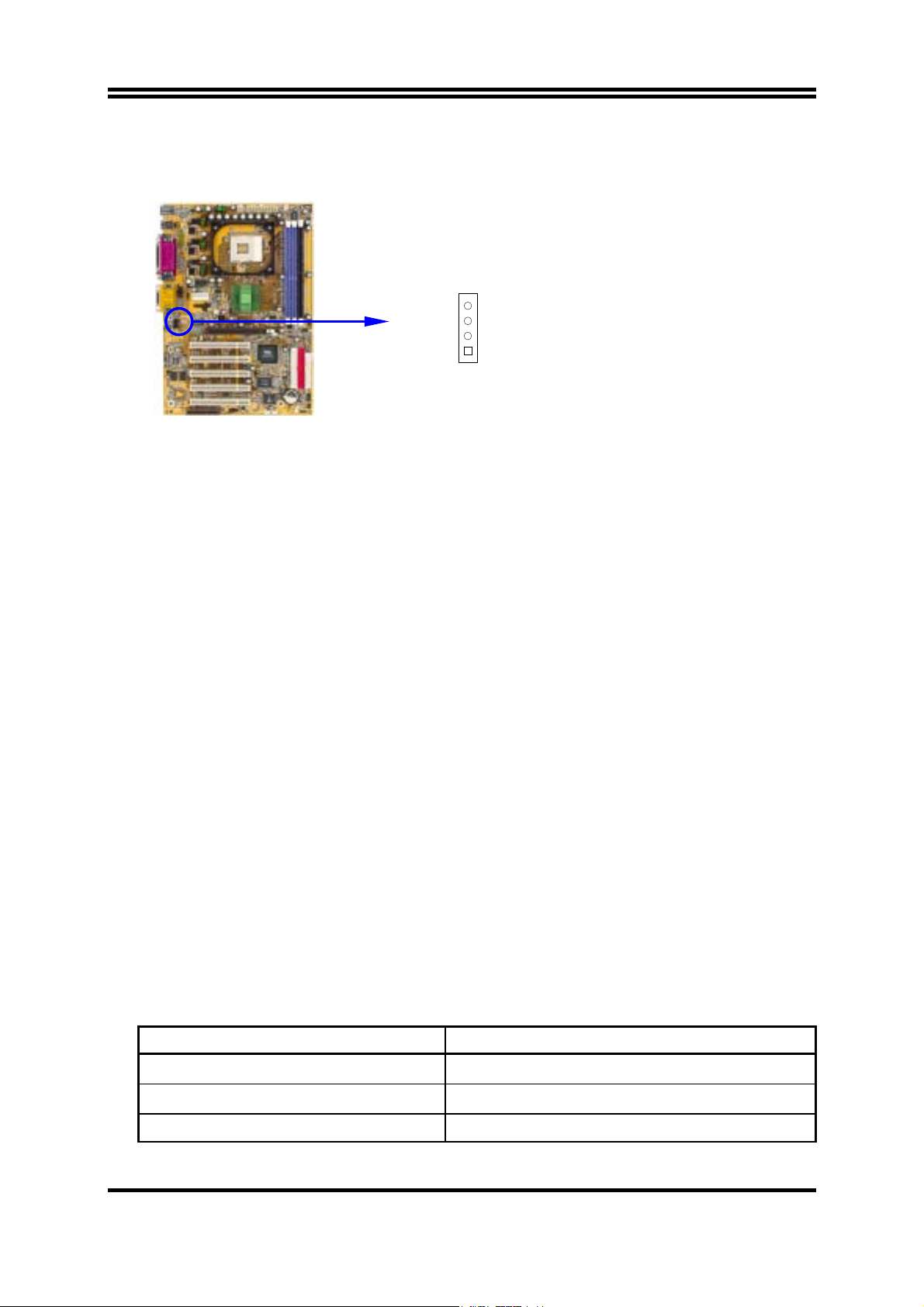
CD_IN are the connectors for CD-Audio Input signal. Please connect it to CD-ROM
CD-Audio output connector.
CD_IN
4
1
CD Audio-In Headers
2-7 Starting Up Your Computer
1. After all connection are made, close your computer case cover.
2. Be sure all the switch are off, and check that the power supply input voltage is set to
proper position, usually in-put voltage is 220V∼240V or 110V∼120V depending on
your country’s voltage used.
3. Connect the power supply cord into the power supply located on the back of your
system case according to your system user’s manual.
4. Turn on your peripheral as following order:
a. Your monitor.
b. Other external peripheral (Printer, Scanner, External Modem etc…)
c. Your system power. For ATX power supplies, you need to turn on the power supply
and press the ATX power switch on the front side of the case.
5. The power LED on the front panel of the system case will light. The LED on the
monitor may light up or switch between orange and green after the system is on. If it
complies with green standards or if it is has a power standby feature. The system will
then run power-on test. While the test are running, the BIOS will alarm beeps or
additional message will appear on the screen.
If you do not see any thing within 30 seconds from the time you turn on the power.
The system may have failed on power-on test. Recheck your jumper settings and
connections or call your retailer for assistance.
Beep Meaning
One short beep when displaying logo No error during POST
Long beeps in an endless loop No DRAM install or detected
One long beep followed by three short Video card not found or video card memory
18
Page 22

beeps bad
High frequency beeps when system is
working
CPU overheated
System running at a lower frequency
During power-on, press <Delete> key to enter BIOS setup. Follow the instructions in
6.
BIOS SETUP.
7.
Power off your computer:
You must first exit or shut down your operating system
before switch off the power switch. For ATX power supply, you can press ATX power
switching after exiting or shutting down your operating system. If you use Windows 9X,
click
“Start”
button, click
“Shut down”
and then click
“Shut down the computer?”
The power supply should turn off after windows shut down.
Chapter 3
Introducing BIOS
The BIOS is a program located on a Flash Memory on the motherboard. This program is a
bridge between motherboard and operating system. When you start the computer, the BIOS
program gain control. The BIOS first operates an auto-diagnostic test called POST (power on
self test) for all the necessary hardware, it detects the entire hardware device and configures
the parameters of the hardware synchronization. Only when these tasks are completed done
it gives up control of the computer to operating system (OS). Since the BIOS is the only
channel for hardware and software to communicate, it is the key factor for system stability,
and in ensuring that your system performance as its best.
In the BIOS Setup main menu of Figure 3-1, you can see several options. We will explain
these options step by step in the following pages of this chapter, but let us first see a short
description of the function keys you may use here:
Press <Esc> to quit the BIOS Setup.
•
•
Press
↑↓←→
(up, down, left, right) to choose, in the main menu, the option you want
to confirm or to modify.
Press <F10> when you have completed the setup of BIOS parameters to save these
•
parameters and to exit the BIOS Setup menu.
Press Page Up/Page Down or +/– keys when you want to modify the BIOS parameters
•
for the active option.
3-1 Entering Setup
Power on the computer and by pressing <Del> immediately allows you to enter Setup.
If the message disappears before your respond and you still wish to enter Setup, restart the
system to try again by turning it OFF then ON or pressing the “RESET” button on the
19
Page 23
system case. You may also restart by simultaneously pressing <Ctrl>, <Alt> and
<Delete> keys. If you do not press the keys at the correct time and the system does not
boot, an error message will be displayed and you will again be asked to
Press <F1> to continue, <Ctrl-Alt-Esc> or <Del> to enter Setup
3-2 Getting Help
Main Menu
The on-line description of the highlighted setup function is displayed at the bottom of the
screen.
Status Page Setup Menu/Option Page Setup Menu
Press F1 to pop up a small help window that describes the appropriate keys to use and the
possible selections for the highlighted item. To exit the Help Window, press <Esc>.
3-3 The Main Menu
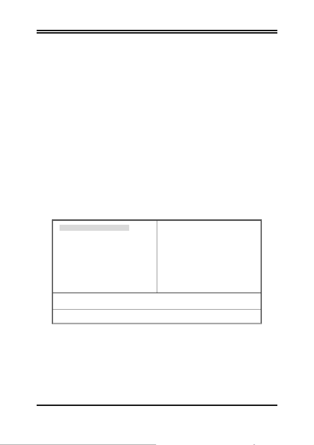
Once you enter Award BIOS CMOS Setup Utility, the Main Menu (Figure 3-1) will
appear on the screen. The Main Menu allows you to select from fourteen setup functions
and two exit choices. Use arrow keys to select among the items and press <Enter> to
accept or enter the sub-menu.
CMOS Setup Utility – Copyright(C) 1984-2001 Award Software
Standard CMOS Features
Advanced BIOS Features
Advanced Chipset Features
Integrated Peripherals
Power Management Setup
PnP/PCI Configurations
PC Health Status
Esc : Quit
F10 : Save & Exit Setup
Time, Date, Hard Disk Type...
Figure 3-1
Miscellaneous Control
Load optimized Defaults
Load Standard Defaults
Set Supervisor Password
Set User Password
Save & Exit Setup
Exit Without Saving
↑↓→ ←
: Select Item
Standard CMOS Features
Use this Menu for basic system configurations.
Advanced BIOS Features
Use this menu to set the Advanced Features available on your system.
Advanced Chipset Features
20
Page 24

Use this menu to change the values in the chipset registers and optimize your system’s
performance.
Integrated Peripherals
Use this menu to specify your settings for integrated peripherals.
Power Management Setup
Use this menu to specify your settings for power management.
PnP/PCI configurations
This entry appears if your system supports PnP/PCI.
PC Health Status
This entry shows your PC health status.
Miscellaneous Control
Use this menu to specify your settings for Miscellaneous control.
Load Optimized Defaults
Use this menu to load the BIOS default values these are setting for optimal performances system
operations for performance use.
Load Standard Defaults
Use this menu to load the BIOS default values for the stable performance system operation
that are factory settings for normal use.
Set Supervisor/User Password
Use this menu to set User and Supervisor Passwords.
Save & Exit Setup
Save CMOS value changes to CMOS and exit setup.
Exit Without Saving
Abandon all CMOS value changes and exit setup.
3-4 Standard CMOS Features
The items in Standard CMOS Setup Menu are divided into several categories. Each
category includes no, one or more than one setup items. Use the arrow keys to highlight
the item and then use the <PgUp> or <PgDn> keys to select the value you want in each
item.
CMOS Setup Utility – Copyright(C) 1984-2001 Award Software
Standard CMOS Features
Date (mm:dd:yy) Mon, Oct, 26 2001
Time (hh:mm:ss) 16 : 48 : 35
Item Help
21
Page 25

> IDE Primary Master Press Enter None
> IDE Primary Slave Press Enter None
> IDE Secondary Master Press Enter None
> IDE Secondary Slave Press Enter None
Drive A 1.44M, 3.25 in.
Drive B None
Video EGA/VGA
Halt On All,But Keyboard
Base Memory 640K
Extended Memory 56320K
Total Memory 57344K
↑↓→←
Move Enter:Select +/-/PU/PD:Value F10:Save ESC:Exit F1:General Help
F5:Previous Values F6:Optimized Defaults F7:Standard Defaults
Menu Level >
Change the day, month,
year and century
Date
The date format is <day><month><date><year>.
Day Day of the week, from Sun to Sat, determined by BIOS. Read-only.
Month The month from Jan. through Dec.
Date The date from 1 to 31 can be keyed by numeric function keys.
Year The year depends on the year of the BIOS.
Time
The time format is <hour><minute><second>.
Primary Master/Primary Slave
Secondary Master/Secondary Slave
Press PgUp/<+> or PgDn/<–> to select Manual, None, Auto type. Note that the
specifications of your drive must match with the drive table. The hard disk will not work
properly if you enter improper information for this category. If your hard disk drive type is
not matched or listed, you can use Manual to define your own drive type manually.
If you select Manual, related information is asked to be entered to the following items.
Enter the information directly from the keyboard. This information should be provided in
the documentation from your hard disk vendor or the system manufacturer.
If the controller of HDD interface is SCSI, the selection shall be “None”.
If the controller of HDD interface is CD-ROM, the selection shall be “None”
Access Mode The settings are Auto Normal, Large, and LBA.
Cylinder number of cylinders
Head number of heads
Precomp write precomp
Landing Zone landing zone
Sector number of sectors
3-5 Advanced BIOS Features
CMOS Setup Utility – Copyright(C) 1984-2001 Award Software
Advanced BIOS Features
22
Page 26
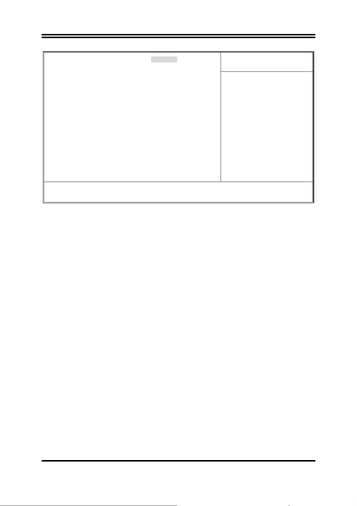
Anti-Virus Protection Disabled
CPU L1 Cache Enabled
CPU L2 Cache Enabled
Quick Power On Self Test Enabled
First Boot Device Floppy
Second Boot Device HDD-0
Third Boot Device CDROM
Boot other Device Enabled
Swap Floppy Drive Disabled
Boot Up Floppy Seek Enabled
Boot Up NumLock Status On
Typematic Rate Setting Disabled
Typematic Rate (Chars/Sec) 6
Typematic Delay (Msec) 250
Security Option Setup
OS Select For DRAM > 64MB Non-OS2
HDD S.M.A.R.T. Capability Disabled
Report No FDD For Windows Yes
Video BIOS Shadow Enabled
↑↓→←
Move Enter:Select +/-/PU/PD:Value F10:Save ESC:Exit F1:General Help
F5:Previous Values F6:Optimized Defaults F7:Standard Defaults
Item Help
Menu Level >
Anti-Virus Protection
Allows you to choose the VIRUS Warning feature for IDE Hard Disk boot sector protection.
If this function is enabled and someone attempt to write data into this area, BIOS will show
a warning message on screen and alarm beep.
Disabled (default) No warning message to appear when anything attempts to access the
boot sector or hard disk partition table.
Enabled Activates automatically when the system boots up causing a warning
message to appear when anything attempts to access the boot sector
of hard disk partition table.
CPU Internal Cache
The default value is Enabled.
Enabled (default) Enable cache
Disabled Disable cache
Note: The internal cache is built in the processor.
External Cache
Choose Enabled or Disabled. This option enables the Level 2 cache memory.
CPU L2 Cache ECC Checking
Choose Enabled or Disabled. This option enables the Level 2 cache memory ECC (error
check correction).
Quick Power On Self-Test
This category speeds up Power On Self Test (POST) after you power on the computer. If
this is set to Enabled. BIOS will shorten or skip some check items during POST.
Enabled (default) Enable quick POST
23
Page 27

Disabled Normal POST
First/Second/Third/Fourth Boot Device
The BIOS attempts to load the operating system from the devices in the sequence selected in
these items. The settings are Floppy, LS/ZIP, HDD-0/HDD-1/HDD-3, SCSI, CDROM,
LAD and Disabled.
Swap Floppy Drive
Switches the floppy disk drives between being designated as A and B. Default is Disabled.
Boot Up Floppy Seek
During POST, BIOS will determine if the floppy disk drive installed is 40 or 80 tracks.
360K type is 40 tracks while 760K, 1.2M and 1.44M are all 80 tracks.
Boot Up NumLock Status
The default value is On.
On (default) Keypad is numeric keys.
Off Keypad is arrow keys.
Typematic Rate Setting
Keystrokes repeat at a rate determined by the keyboard controller. When enabled, the
typematic rate and typematic delay can be selected. The settings are: Enabled/Disabled.
Typematic Rate (Chars/Sec)
Sets the number of times a second to repeat a keystroke when you hold the key down. The
settings are: 6, 8, 10, 12, 15, 20, 24, and 30.
Typematic Delay (Msec)
Sets the delay time after the key is held down before is begins to repeat the keystroke. The
settings are 250, 500, 750, and 1000.
Security Option
This category allows you to limit access to the system and Setup, or just to Setup.
System The system will not boot and access to Setup will be denied if the
correct password is not entered at the prompt.
Setup (default) The system will boot, but access to Setup will be denied if the correct
password is not entered prompt.
OS Select For DRAM > 64MB
Allows OS2 to be used with >64MB or DRAM. Settings are Non-OS/2 (default) and
OS2. Set to OS/2 if using more than 64MB and running OS/2.
3-6 Advanced Chipset Features
The Advanced Chipset Features Setup option is used to change the values of the chipset
registers. These registers control most of the system options in the computer.
24
Page 28
CMOS Setup Utility – Copyright(C) 1984-2001 Award Software
Advanced Chipset Features
> DRAM Timing Settings Press Enter
> AGP Timing Settings Press Enter
> PCI Timing Settings Press Enter
System BIOS Cacheable Disabled
Video RAM Cacheable Disabled
Memory Hole Disabled
Item Help
Menu Level >
↑↓→←
Move Enter:Select +/-/PU/PD:Value F10:Save ESC:Exit F1:General Help
F5:Previous Values F6:Optimized Defaults F7:Standard Defaults
DRAM Timing Settings
Please refer to section 3-6-1
AGP Timing Settings
Please refer to section 3-6-2
PCI Timing Settings
Please refer to section 3-6-3
System BIOS Cacheable
Selecting Enabled allows caching of the system BIOS ROM at F0000h-FFFFFh, resulting in
better system performance. However, if any program writes to this memory area, a system
error may result. The settings are: Enabled and Disabled.
Video RAM Cacheable
Select Enabled allows caching of the video BIOS, resulting in better system performance.
However, if any program writes to this memory area, a system error may result. The
settings are: Enabled and Disabled.
Memory Hole
You can reserve this area of system memory for ISA adapter ROM. When this area is
reserved, it cannot be cached. The user information of peripherals that need to use this area
of system memory usually discusses their memory requirements. The settings are: Enabled
and Disabled.
3-6-1 DRAM Timing Settings
CMOS Setup Utility – Copyright(C) 1984-2001 Award Software
DRAM Timing Settings
Auto Configuration Standard
RAS Active Time 6T
Item Help
25
Page 29

RAS Precharge Time 3T
RAS to CAS Delay 3T
CAS Latency 2.5T
Bank Interleave Disabled
DRAM Command Rate 2T Command
Menu Level >>
↑↓→←
Move Enter:Select +/-/PU/PD:Value F10:Save ESC:Exit F1:General Help
F5:Previous Values F6:Optimized Defaults F7:Standard Defaults
RAS Active Time
This field let’s you insert a timing delay between the CAS and RAS strobe signals, used
when DRAM is written to, read from, or refreshed. Fast gives faster performance; and
Slow gives more stable performance. This field applies only when synchronous DRAM is
installed in the system. The settings are: 2T and 3T.
RAS Precharge Time
If an insufficient number of cycles is allowed for the RAS to accumulate its charge before
DRAM refresh, the refresh may be incomplete and the DRAM may fail to retain date. Fast
gives faster performance; and Slow gives more stable performance. This field applies only
when synchronous DRAM is installed in the system. The settings are: 2T and 3T.
CAS Latency
When synchronous DRAM is installed, the number of clock cycles of CAS latency depends
on the DRAM timing. The settings are: 2T and 2.5T.
3-6-2 AGP Timing Settings
CMOS Setup Utility – Copyright(C) 1984-2001 Award Software
AGP Timing Settings
AGP Transfer Aperture Size 64M
AGP Mode Auto
AGP Driving Control Auto
* AGP Driving Value DA
AGP Fast Write Disabled
AGP Master 1 WS Write Enabled
AGP Master 1 WS Read Enabled
CPU to AGP Post Write Disabled
AGP Delay Transaction Disabled
Item Help
Menu Level >>
↑↓→←
Move Enter:Select +/-/PU/PD:Value F10:Save ESC:Exit F1:General Help
F5:Previous Values F6:Optimized Defaults F7:Standard Defaults
Note: Change these settings only if you are familiar with the chipset.
3-6-3 PCI Timing Settings
CMOS Setup Utility – Copyright(C) 1984-2001 Award Software
PCI Timing Settings
26
Page 30
PCI Master 1 WS Write Disabled
PCI Master 1 WS Read Disabled
CPU to PCI Write Buffer Enabled
PCI Delay Transaction Disabled
Item Help
Menu Level >>
↑↓→←
Move Enter:Select +/-/PU/PD:Value F10:Save ESC:Exit F1:General Help
F5:Previous Values F6:Optimized Defaults F7:Standard Defaults
PCI Delay Transaction
The chipset has an embedded 32-bit posted write buffer to support delay transactions cycles.
Select Enabled to support compliance with PCI specification version 2.1. The settings are:
Enabled and Disabled.
3-7 Integrated Peripherals
CMOS Setup Utility – Copyright(C) 1984-2001 Award Software
Integrated Peripherals
> OnChip IDE Function Press Enter
> OnChip Device Function Press Enter
> Onboard Super IO Function Press Enter
Init Display First PCI Slot
↑↓→←
Move Enter:Select +/-/PU/PD:Value F10:Save ESC:Exit F1:General Help
F5:Previous Values F6:Optimized Defaults F7:Standard Defaults
OnChip IDE Function
Please refer to section 3-7-1
Item Help
Menu Level >
OnChip Device Function
Please refer to section 3-7-2
Onboard Super IO Function
Please refer to section 3-7-3
Init Display First
This item allows you to decide to activate whether PCI Slot or AGP VGA first. The
settings are: PCI Slot, AGP Slot.
3-7-1 OnChip IDE Function
CMOS Setup Utility – Copyright(C) 1984-2001 Award Software
OnChip IDE Function
OnChip IDE Channel0 Enabled
OnChip IDE Channel1 Enabled
27
Item Help
Page 31

Primary Master PIO Auto
Primary Slave PIO Auto
Secondary Master PIO Auto
Secondary Slave PIO Auto
Primary Master UDMA Auto
Primary Slave UDMA Auto
Secondary Master UDMA Auto
Secondary Slave UDMA Auto
IDE 32-bit Transfer Mode Enabled
IDE HDD Block Mode Enabled
IDE Prefetch Mode Enabled
Delay For HDD (Secs) 0
Menu Level >>
↑↓→←
Move Enter:Select +/-/PU/PD:Value F10:Save ESC:Exit F1:General Help
F5:Previous Values F6:Optimized Defaults F7:Standard Defaults
OnChip IDE Channal0/Channel1
The integrated peripheral controller contains an IDE interface with support for two IDE
channels. Select Enabled to activate each channel separately. The settings are: Enabled and
Disabled.
Primary/Secondary Master/Slave PIO
The four IDE PIO (Programmed Input/Output) fields let you set a PIO mode (0-4) for each
of the four IDE devices that the onboard IDE interface supports. Modes 0 through 4
provide successively increased performance. In Auto mode, the system automatically
determines the best mode for each device. The settings are: Auto, Mode 0, Mode 1, Mode
2, Mode 3, Mode 4.
Primary/Secondary Master/Slave UDMA
Ultra DMA/33 implementation is possible only if your IDE hard drive supports it and the
operating environment includes a DMA driver (Windows 95 OSR2 or a third-party IDE bus
master driver). If your hard drive and your system software both support Ultra DMA/33
and Ultra DMA/66, select Auto to enable BIOS support. The settings are: Auto, Disabled.
IDE HDD Block Mode
Block mode is also called block transfer, multiple commands, or multiple sector read/write.
If your IDE hard drive supports block mode (most new drives do), select Enabled for
automatic detection of the optimal number of block read/writes per sector the drive can
support. The settings are: Enabled, Disabled.
3-7-2 OnChip Device Function
CMOS Setup Utility – Copyright(C) 1984-2001 Award Software
OnChip Device Function
AC97 Sound Device Auto
Game Port Address 201
Item Help
28
Page 32

Midi Port Address Disabled
Midi Port IRQ 10
AC97 Modem Device Auto
USB Host Controller Enabled
USB Keyboard Legacy Support Disabled
↑↓→←
Move Enter:Select +/-/PU/PD:Value F10:Save ESC:Exit F1:General Help
F5:Previous Values F6:Optimized Defaults F7:Standard Defaults
Menu Level >>
AC97 Sound Device
This item allows you to decide to enable/disable the chipset family to support AC97 Audio.
The settings are: Enabled, Disabled.
Game Port Address/Midi Port Address
This will determine which Address the Game Port/Midi Port will use.
AC97 Modem Device
This item allows you to decide to enable/disable the chipset family to support AC97 Modem.
The settings are: Auto, Disabled.
USB Host Controller
Select Enabled if your system contains a Universal Serial Bus (USB) controller and you
have a USB peripherals. The settings are: Enabled, Disabled.
USB Keyboard Support
Select Enabled if your system contains a Universal Serial Bus (USB) controller and you
have a USB keyboard. The settings are: Enabled, Disabled.
3-7-3 Onboard Super IO Function
CMOS Setup Utility – Copyright(C) 1984-2001 Award Software
Onboard Super IO Function
Onboard FDD Controller Enabled
Onboard Serial Port 1 3F8/IRQ4
Onboard Serial Port 2 2F8/IRQ3
UART2 Mode Normal
RxD, TxD Active Hi, Lo
IR Duplex Mode Half
Use IR Pins IRRX/IRTX
Onboard Parallel Port 378/IRQ7
Parallel Mode SPP
EPP Mode Select EPP1.7
ECP Mode Use DMA 3
Item Help
Menu Level >>
29
Page 33

↑↓→←
Move Enter:Select +/-/PU/PD:Value F10:Save ESC:Exit F1:General Help
F5:Previous Values F6:Optimized Defaults F7:Standard Defaults
Onboard FDD Controller
Select Enabled if your system has a floppy disk controller (FDD) installed on the system board and
you wish to use it. If you install add-on FDC or the system has no floppy drive, select Disabled in
this field. The settings are: Enabled and Disabled.
Onboard Serial Port 1/Port 2
Select an address and corresponding interrupt for the first and the second serial ports. The settings
are: 3F8/IRQ4, 2E8/IRQ3, 3E8/IRQ4, 2F8/IRQ3, Disabled, Auto.
UART2 Mode
This item allows you to determine which InfraRed(IR) function of the onboard I/O chip, this
functions uses.
Onboard Parallel Port
There is a built-in parallel port on the on-board Super I/O chipset that Provides Standard, ECP, and
EPP features. It has the following option:
Disabled
(3BCH/IRQ7)/
(278H/IRQ5)/
(378H/IRQ7)
Line Printer port 0
Line Printer port 2
Line Printer port 1
Parallel Port Mode
SPP : Standard Parallel Port
EPP : Enhanced Parallel Port
ECP : Extended Capability Port
SPP/EPP/ECP/ECP+EPP
To operate the onboard parallel port as Standard Parallel Port only, choose “SPP.” To operate
the onboard parallel port in the EPP modes simultaneously, choose “EPP.” By choosing
“ECP”, the onboard parallel port will operate in ECP mode only. Choosing “ECP+EPP” will
allow the onboard parallel port to support both the ECP and EPP modes simultaneously. The
ECP mode has to use the DMA channel, so choose the onboard parallel port with the ECP
feature. After selecting it, the following message will appear: “ECP Mode Use DMA” at this
time, the user can choose between DMA channels 3 to 1. The onboard parallel port is EPP
Spec. compliant, so after the user chooses the onboard parallel port with the EPP function, the
following message will be displayed on the screen: “EPP Mode Select.” At this time either
EPP 1.7 spec. or EPP 1.9 spec. can be chosen.
3-8 Power Management Setup
The Power Management Setup allows you to configure your system to most effectively save
energy saving while operating in a manner consistent with your own style of computer use.
CMOS Setup Utility – Copyright(C) 1984-2001 Award Software
Power Management Setup
ACPI Function Enabled
Video Off Option Always off
30
Item Help
Page 34

Video off Method V/H SYNC+Blank
MODEM Use IRQ 3
Power Button Function Instant-Off
Power After Power Failure Off
> Wake Up Events Press Enter
↑↓→←
Move Enter:Select +/-/PU/PD:Value F10:Save ESC:Exit F1:General Help
F5:Previous Values F6:Optimized Defaults F7:Standard Defaults
Menu Level >
ACPI Function
This item allows you to Enabled/Disabled the Advanced Configuration and Power
Management (ACPI). The settings are Enabled and Disabled.
Video Off Option
This determines the manner in which the monitor is blanked. The choice are Suspend →
off, All Modes → Off, and Always On.
Video Off Method
This determines the manner in which the monitor is blanked.
DPMS
Blank Screen
V/H SYNC+Blank
(default) Initial display power management signaling.
This option only writes blanks to the video buffer.
This selection will cause the system to turn off the vertical and
horizontal synchronization ports and write blanks to the video
buffer.
Modem Use IRQ
This determines the IRQ in which the MODEM can use.
The settings are: 3, 4, 5, 7, 9, 10, 11, NA.
Power Button Function
Pressing the power button for more than 4 seconds forces the system to enter the Soft-Off
state. The settings are: Delay 4 Sec, Instant-Off.
Wake Up Events
Please refer to section 3-8-1
3-8-1 Wake up Events
CMOS Setup Utility – Copyright(C) 1984-2001 Award Software
Wake Up Events
VGA OFF
LPT & COM LPT/COM
Item Help
31
Page 35

HDD & FDD ON
PCI Master OFF
Wake-Up on Ring/LAN Disabled
Wake-Up on PCI PME Disabled
Wake-Up on RTC Alarm Disabled
x Date of Month Alarm 0
x Time (hh:mm:ss) Alarm 0 : 0 : 0
> IRQs Activities Press Enter
↑↓→←
Move Enter:Select +/-/PU/PD:Value F10:Save ESC:Exit F1:General Help
F5:Previous Values F6:Optimized Defaults F7:Standard Defaults
Menu Level >>
Wake Up On Ring/PME
During Disabled, the system will ignore any incoming call from the modem. During
Enabled, the system will boot up if there’s an incoming call from the modem.
Wake-Up on RTC Alarm
This function is for setting date and time for your computer to boot up. During Disabled,
you cannot use this function. During Enabled, choose the Date and Time Alarm:
Date(of month) Alarm
You can choose which month the system will boot up. Set to 0, to boot every day.
Time(hh:mm:ss) Alarm
You can choose what hour, minute and second the system will boot up.
Note: If you have change the setting, you must let the system boot up until it goes to
the operating system, before this function will work.
IRQs Activities
Please refer to section 3-8-1.1
3-8-1.1 IRQs Activities
CMOS Setup Utility – Copyright(C) 1984-2001 Award Software
IRQs Activities
Primary INTR ON
IRQ3 (COM 2) Enabled
IRQ4 (COM 1) Enabled
IRQ5 (LPT 2) Enabled
IRQ6 (Floppy Disk) Enabled
IRQ7 (LPT 1) Enabled
IRQ8 (RTC Alarm) Disabled
IRQ9 (IRQ2 Redir) Disabled
IRQ10 (Reserved) Disabled
IRQ11 (Reserved) Disabled
IRQ12 (PS/2 Mouse) Enabled
IRQ13 (Coprocessor) Disabled
IRQ14 (Hard Disk) Enabled
IRQ15 (Reserved) Disabled
↑↓→←
Move Enter:Select +/-/PU/PD:Value F10:Save ESC:Exit F1:General Help
F5:Previous Values F6:Optimized Defaults F7:Standard Defaults
Item Help
Menu Level >>>
3-9 PnP/PCI Configuration Setup
This section describes configuring the PCI bus system. PCI, or Personal Computer
Interconnect, is a system which allows I/O devices to operate at speeds nearing the speed
the CPU itself uses when communicating with its own special components. This section
covers some very technical items and it is strongly recommended that only experienced
32
Page 36
users should make any changes to the default settings.
CMOS Setup Utility – Copyright(C) 1984-2001 Award Software
PnP/PCI Configurations
PnP OS Installed No
Reset Configuration Data Disabled
Resources Controlled By Manual
x IRQ Resources Press Enter
PCI/VGA Palette Snoop Disabled
Assign IRQ For VGA Enabled
Assign IRQ For USB Enabled
↑↓→←
Move Enter:Select +/-/PU/PD:Value F10:Save ESC:Exit F1:General Help
F5:Previous Values F6:Optimized Defaults F7:Standard Defaults
Item Help
Menu Level >
Reset Configuration Data
Normally, you leave this field Disabled. Select Enabled to reset Extended System Configuration
Data (ESCD) when you exit Setup if you have installed a new add-on and the system
reconfiguration has caused such a serious conflict that the operating system can not boot.
The settings are: Enabled and Disabled.
Resource Controlled By
The Award Plug and Play BIOS has the capacity to automatically configure all of the boot
and Plug and Play compatible devices. However, this capability means absolutely nothing
unless you are using a Plug and Play operating system such as Windows95/98. If you set
this field to “manual” choose specific resources by going into each of the sub menu that
follows this field (a sub menu is preceded by a “>”).
The settings are: Auto(ESCD), Manual.
IRQ Resources
When resources are controlled manually, assign each system interrupt a type, depending on
the type of device using the interrupt.
Please refer to section 3-9-1
PCI/VGA Palette Snoop
Leave this field at Disabled. The settings are Enabled, Disabled.
3-9-1 IRQ Resources
CMOS Setup Utility – Copyright(C) 1984-2001 Award Software
IRQ Resources
IRQ3 assigned to PCI Device
IRQ4 assigned to PCI Device
33
Item Help
Page 37

IRQ5 assigned to PCI Device
IRQ7 assigned to PCI Device
IRQ9 assigned to PCI Device
IRQ10 assigned to PCI Device
IRQ11 assigned to PCI Device
IRQ12 assigned to PCI Device
IRQ14 assigned to PCI Device
IRQ15 assigned to PCI Device
↑↓→←
Move Enter:Select +/-/PU/PD:Value F10:Save ESC:Exit F1:General Help
F5:Previous Values F6:Optimized Defaults F7:Standard Defaults
Menu Level >>
3-10 PC Health Status
This section shows the Status of you CPU, Fan, Warning for overall system status. This is
only available if there is Hardware Monitor onboard.
CMOS Setup Utility – Copyright(C) 1984-2001 Award Software
PC Health Status
Shutdown Temperature Disabled
CPU Warning Temperature Disabled
Show PC Health in Post Enabled
Current System Temperature 25°C
Current CPU Temperature 38°C
CPUFAN 5000 rpm
SYSFAN 5000 rpm
Vcore 1.78V
Vcc3.3 3.31V
+ 5V 4.98V
+12V 12.22V
-12V -12.36V
-5V -5.09V
VBAT(V) 3.21V
5VSB(V)
↑↓→←
Move Enter:Select +/-/PU/PD:Value F10:Save ESC:Exit F1:General Help
F5:Previous Values F6:Optimized Defaults F7:Standard Defaults
5.02V
Item Help
Menu Level >
Shutdown Temperature
This item can let users setting the Shutdown temperature, when CPU temperature over this
setting the system will auto shutdown to protect CPU.
Show PC Health in Post
During Enabled, it displays information list below. The choice is either Enabled or Disabled
Current CPU Temperature/Current System Temp/Current FAN1, FAN2 Speed/Vcore/
Vdd/3.3V/+5V/+12V/-12V/VBAT(V)/5VSB(V)
This will show the CPU/FAN/System voltage chart and FAN Speed.
Detect CPUFAN in Post
During Enabled, system will warn the user if CPU Fan is not functioning.
3-11 Miscellaneous Control
This section is for setting CPU Frequency/Voltage Control.
CMOS Setup Utility – Copyright(C) 1984-2001 Award Software
Miscellaneous Control
34
Page 38

CPU Clock Ratio 8X
Auto Detect DIMM/PCI Clk Enabled
Spread Spectrum Disabled
** Current Host/PCI Clock is 100/33MHz **
Host/PCI Clock at Next Boot is 100/33MHz
** Current DRAM Clock is 133MHz **
DRAM Clock at next Boot is 133MHz
AGP VddQ Select 1.5V (Default)
+2.5V Select 2.5V (Default)
VDIMM Select Default
Item Help
Menu Level >
↑↓→←
Move Enter:Select +/-/PU/PD:Value F10:Save ESC:Exit F1:General Help
F5:Previous Values F6:Optimized Defaults F7:Standard Defaults
Auto Detect DIMM/PCI Clk
This item allows you to enable/disable auto detect DIMM/PCI Clock.
Spread Spectrum
This item allows you to set the CPU Host/PCI clock and Spread Spectrum.
The settings are: Enabled, Disabled.
Host/PCI Clock at next Boot is
This item allows you to select CPU frequency step by step increasing
The choice are: 100MHz∼132MHz, 133MHz∼200MHz.
DRAM Clock at next Boot is
This field displays the capability of the memory modules that you can use
The choice is either 100MHz or 133MHz (only select CPU Frequency 100MHz.)
AGP VddQ Select
This item allows you to select 1.5V of the AGP 4X VGA card. The choice are: 1.5V, 1.6V.
VDIMM Select
This item allows you to select 2.5V of the DDR Module. The choice are: 2.5V, 2.6V, 2.7V,
2.8V.
3-12 Load Standard/Optimized Defaults
Load Standard Defaults
When you press <Enter> on this item, you get confirmation dialog box with a message
similar to:
35
Page 39

Load Standard Defaults (Y/N)? N
Pressing <Y> loads the BIOS default values for the most stable, minimal-performance
system operations.
Load Optimized Defaults
When you press <Enter> on this item, you get a confirmation dialog box with a message
similar to:
Load Optimized Defaults (Y/N)? N
Pressing <Y> loads the default values that are factory settings for optimal performance
system operations.
3-13 Set Supervisor/User Password
You can set either supervisor or user password, or both of them. The differences are:
Supervisor password: Can enter and change the options of the setup menus.
User password: Can only enter but do not have the right to change the options of
the setup menus. When you select this function, the following
message will appear at the center of the screen to assist you in
creating a password.
ENTER PASSWORD:
Type the password, up to eight characters in length, and press <Enter>. The password
typed now will clear any previously entered password from CMOS memory. You will be
asked to confirm the password. Type the password again and press <Enter>. You may
also press <Esc> to abort the selection and not enter a password.
To disable a password, just press <Enter> when you are prompted to enter the password.
A message will confirm that the password will be disabled. Once the password is disabled,
the system will boot and you can enter Setup freely.
PASSWORD DISABLED.
When a password has been enabled, you will be prompted to enter it every time you try to
enter Setup. This prevents an unauthorized person from changing any part of your system
configuration.
Additionally, when a password is enabled, you can also require the BIOS to request a
password every time your system is rebooted. This would prevent unauthorized use of your
computer.
You determine when the password is required within the BIOS Features Setup Menu and its
Security option. If the Security option is set to “System”, the password will be required
both at boot and at entry to Setup. If set to “Setup”, prompting only occurs when trying to
enter Setup.
Chapter 4
DRIVER & FREE PROGRAM INSTALLATION
36
Page 40
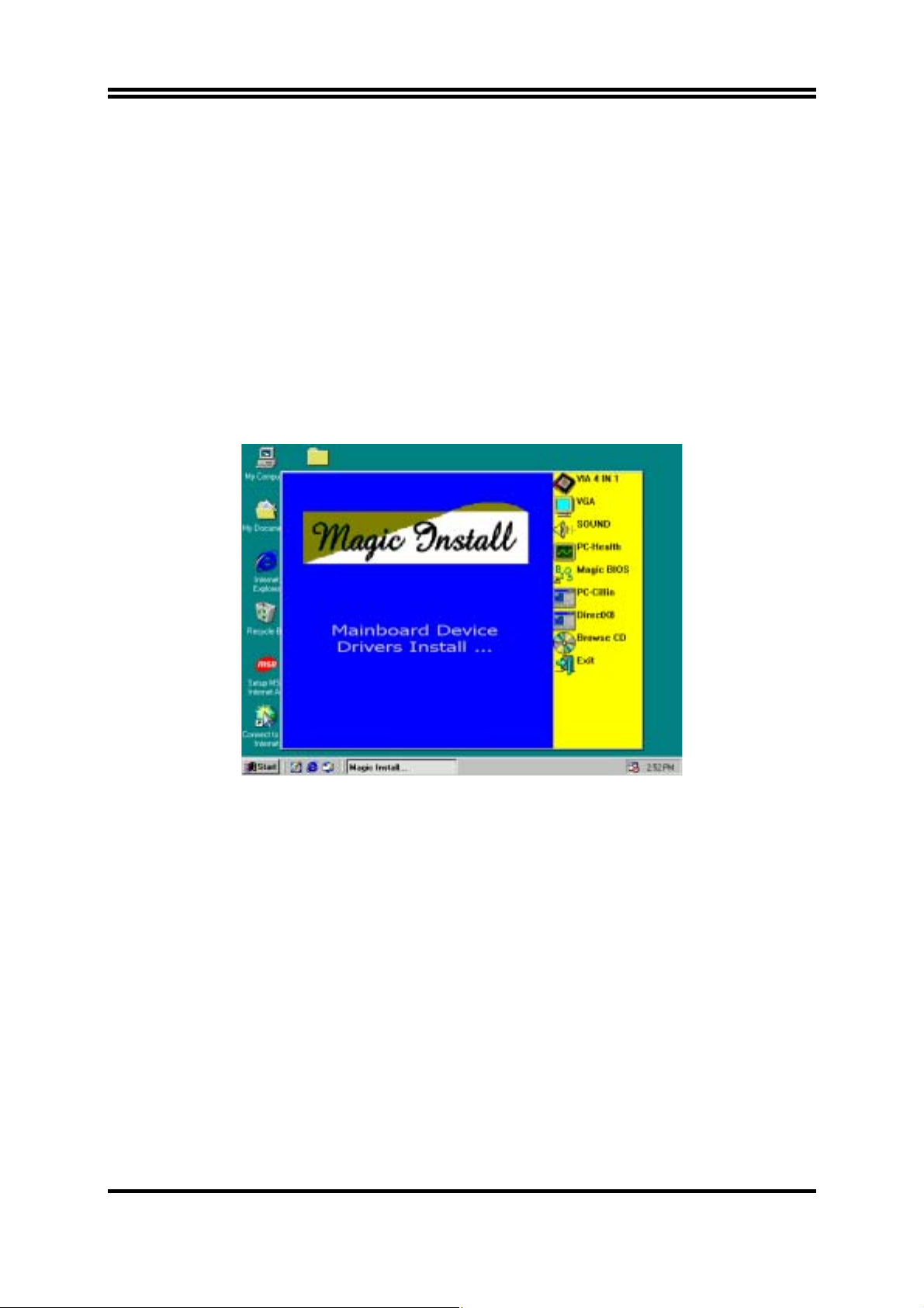
Check your package and there is A MAGIC INSTALL CD included. This CD consists of
all DRIVERS you need and some free application programs and utility programs. In
addition, this CD also include an auto detect software which can tell you which hardware is
installed, and which DRIVERS needed so that your system can function properly. We call
this auto detect software MAGIC INSTALL.
MAGIC INSTALL supports WINDOWS 9X/ME/NT4.0/2000/XP
Insert CD into your CD-ROM drive and the MAGIC INSTALL Menu should appear as
below. If the menu does not appear, double-click MY COMPUTER / double-click CDROM drive or click START / click RUN / type X:\SETUP.EXE (assuming X is your CDROM drive).
From MAGIC INSTALL MENU you may make 9 selections:
1. VIA 4 IN 1 install VIA Service Pack 4 IN 1 driver
2. VGA install VIA VGA Driver (Only for P4MFA)
3. SOUND install AC97 Audio Codec Installing driver
4. PC-HEALTH install Winbond PC-HEALTH hardware monitor Software
5. MAGIC BIOS install BIOS Live Update Utility
6. PC-CILLIN install PC-CILLIN2000 anti-virus program
7. DIRECTX8 install Microsoft DirectX 8.0 driver
8. BROWSE CD to browse the contents of the CD
9. EXIT to exit from MAGIC INSTALL menu
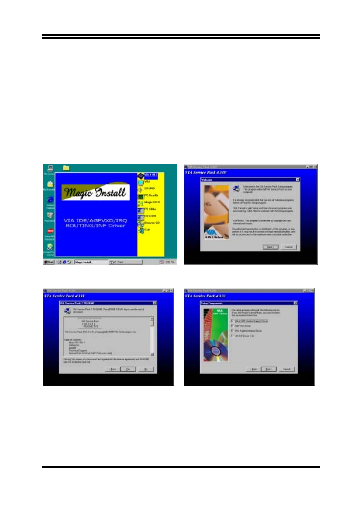
4-1 IDE Install VIA Service Pack 4 IN 1 Driver
* The path of the file is X:\VIA\DRIVER\SETUP.EXE
IDE :
VIA ATAPI VENDOR SUPPORT DRIVER IS USED TO FIXED COMPATIBILITY
37
Page 41
ISSUE FOR IDE DEVICES
AGPVXD :
IRQ ROUTING :
INF :
VIA AGPVXD DRIVER IS TO BE INSTALLED, IF YOU ARE USING AN
AGP VGA CARD, VIAGART.VXD WILL PROVIDE SERVICE ROUTINES
TO YOUR VGA DRIVER AND INTERFACE DIRECTLY TO HARDWARE,
PROVIDING FAST GRAPHIC ACCESS
VIA PCI IRQ MINIPORT DRIVER IS TO BE INSTALLED UNDER WIN98
ONLY, IT WILL FIX PCI IRQ ROUTING SEQUENCE
VIA REGISTRY DRIVER IS TO BE INSTALLED UNDER WINDOWS
THE DRIVER WILL ENABLE VIA POWER MANAGERMENT
CONTROLLER
1. Click IDE when MAGIC INSTALL MENU
appears
3. This is to announce the Copy Write, click
Yes
2. Click NEXT when VIA Service Pack Wizard
appears
4. Click NEXT to choose all driver
38
Page 42
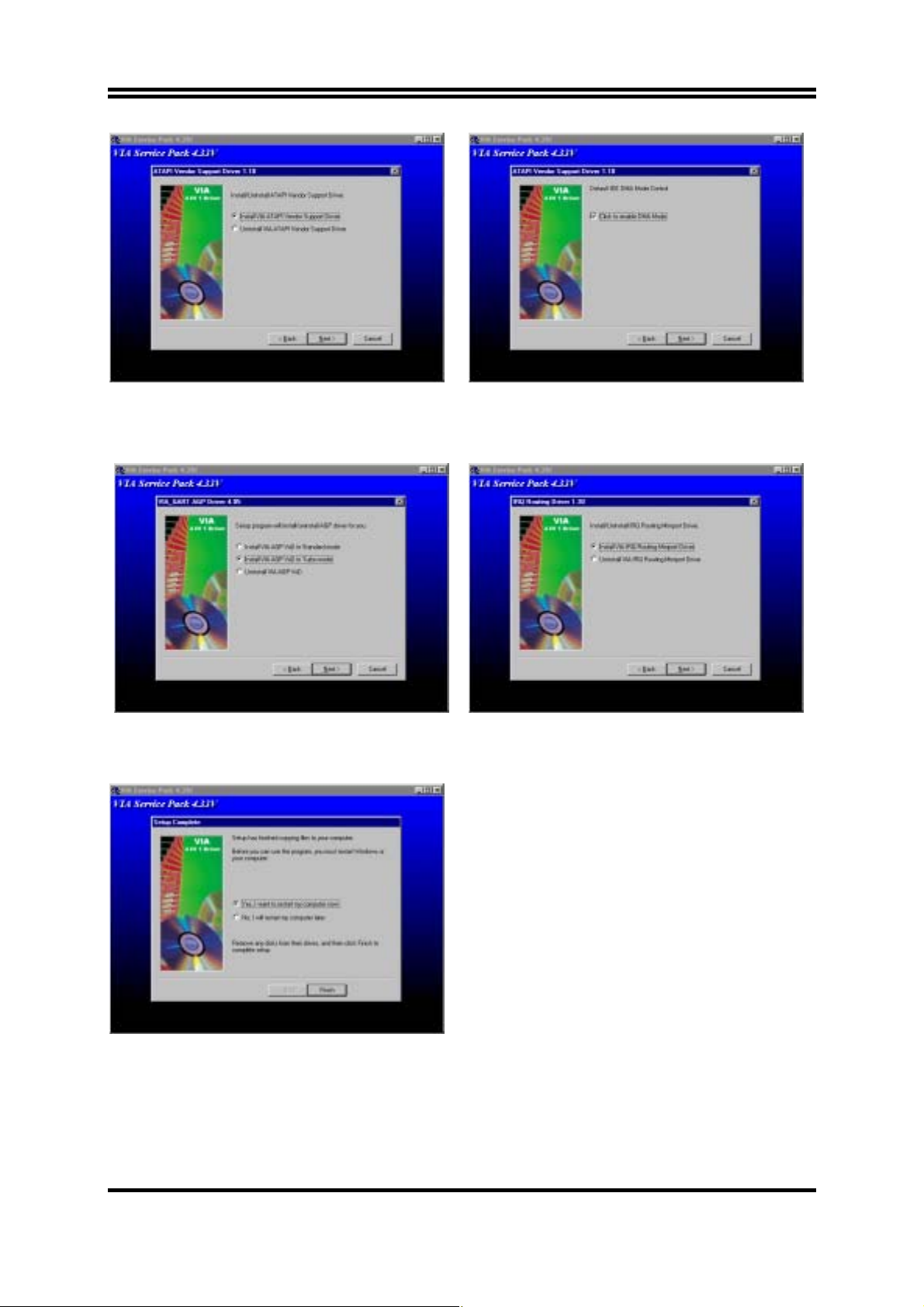
5. Click NEXT to Install ATAPI Vender
6. Click NEXT to choose enabled DMA Mode
Support Driver
7. Click NEXT to Install VIA AGP VXD
Driver
8. Click NEXT to Install VIA IRQ Routing Mini
port Driver
9. Click Finish to restart computer
39
Page 43
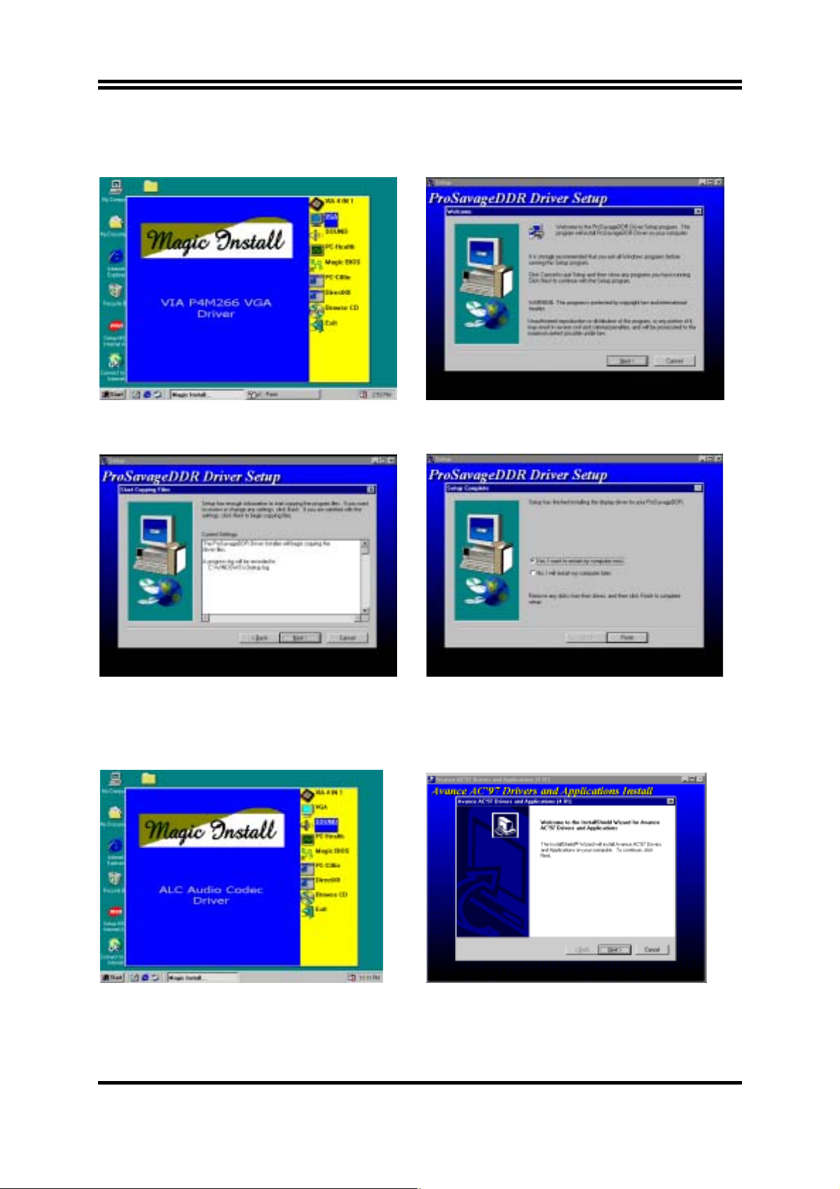
4-2 VGA install VIA P4M266 VGA Driver (Only for P4MFA)
A. For WINDOWS 9X/ME/NT4.0/2000/XP
1. Click VGA when MAGIC INSTALL MENU
appears
2.
Click NEXT When ProSavageDDR Driver
Install Setup Wizard Appears
3.
Click NEXT to Install Driver File
4.
Click Finish to Restart Computer
4-3 Sound Install ALC Audio Codec Driver
1. Click SOUND when MAGIC INSTALL
MENU appears
2. Then auto detect operation system language
edition, click OK, start to install DRIVER
40
Page 44
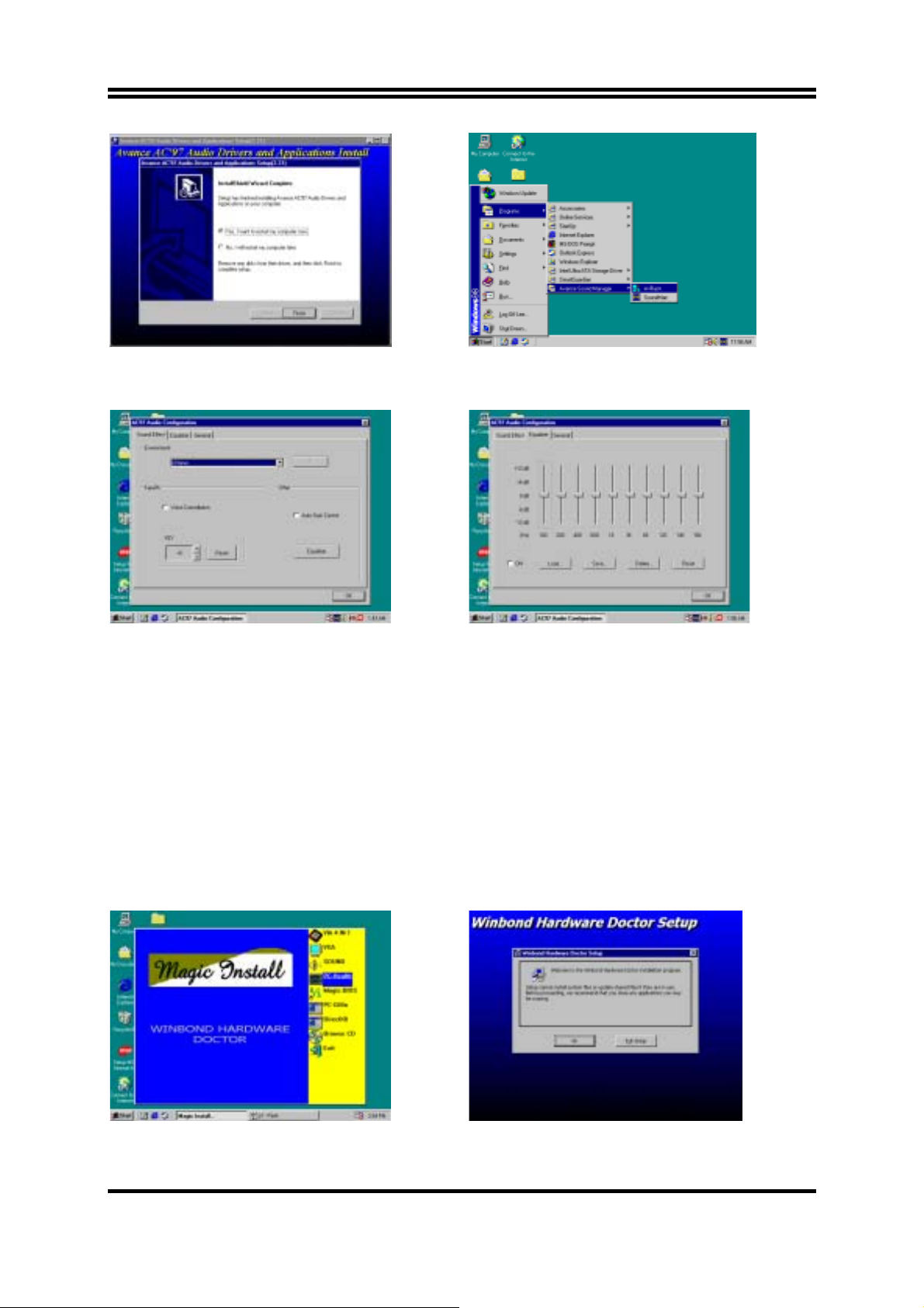
3. Click Finish and Restart Windows
4. Click Start→Program→Avance Sound
Manager→AvRack. Then AVRACK Windows
appears
5. Sound Effect select and KaraOK Mode
Function
6. Manual Sound Effect Setting
Note: The path of the file
For WIN98/NT4.0/WIN2K is X:\CODEC\ALCCODEC\SETUP.EXE
For WIN95 is X:\VIA\VIAUDIO\SETUP.EXE
For Linux is X:\VIA\VIAUDIO\Linux
For Real DOS Mode is X:\VIA\VIAUDIO\VIADOS
4-4 PC-HEALTH Winbond Hardware Doctor Monitoring Software
The path of the file is X:\VIA\HEALTH-W\SETUP.EXE
(Support Windows 9X/ME/2K/NT/XP)
In Windows 95/98 Winbond Hardware Doctor Monitoring Software needs some system files to copy
in Utility that’s why it needs install PC-HEALTH twice to complete setup.
1. Click PC-Health when Magic Install Menu
appears
2. Click OK when Winbond Hardware Doctor
Setup Window appears
41
Page 45
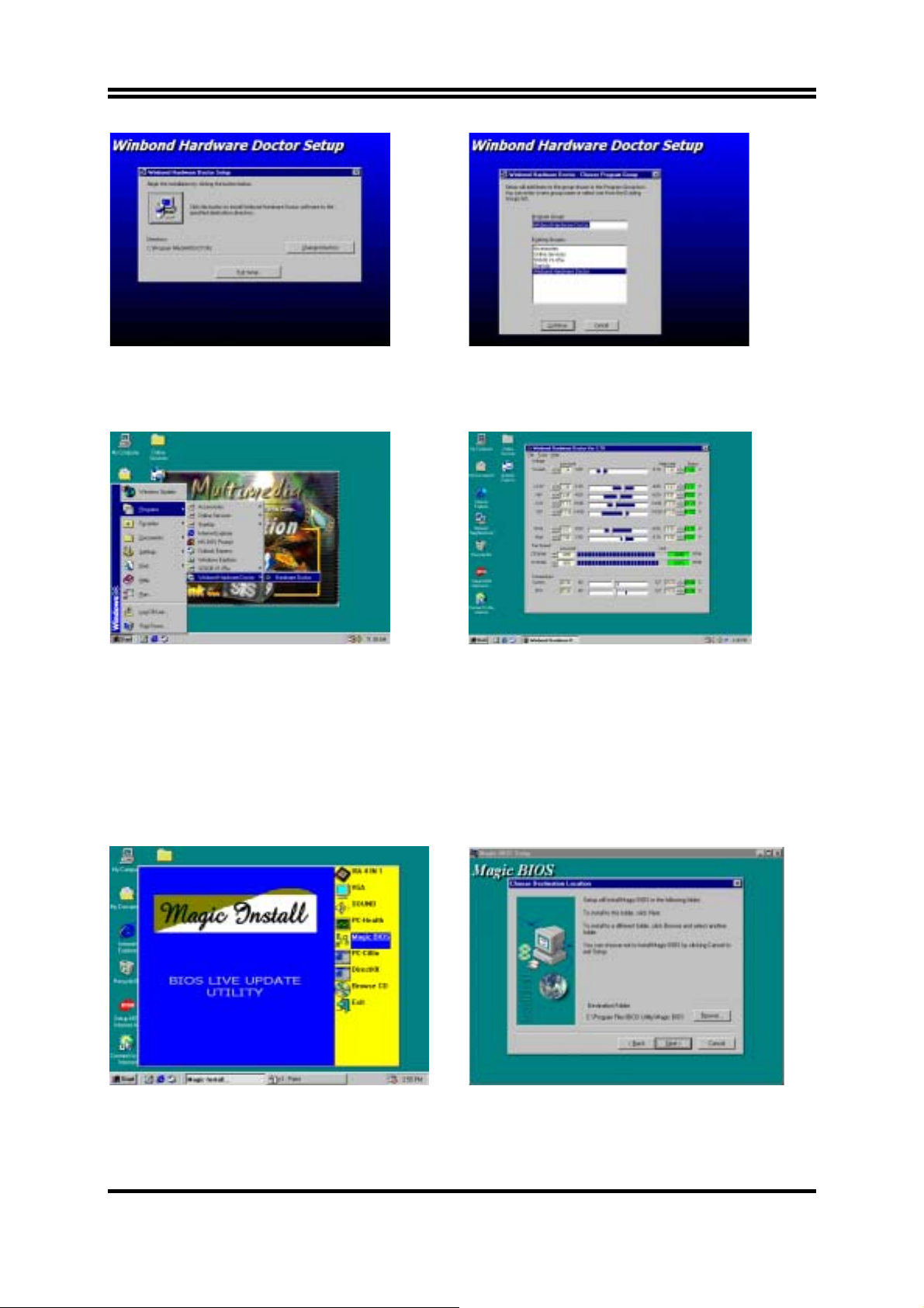
3. Click the Button to start installation 4. Select Program Group name or enter a new
group name, click continue to setup and click
OK after setup complete
4-4-1 How To Utilize PC-HEALTH
1. Click Program → Winbond Hardware
Doctor → Hardware Doctor the Winbond
Hardware Doctor will appears
You can remove the Utility in Control Panel
Add/Remove Program icon
→
2. After executing Winbond Hardware Doctor it
supports system voltage, Fan speed and CPU/
SYSTEM Temperature. Because this is a Ontime Monitoring program therefore the value
will change after it detected, if the value is
over default setting the system will have
warning picture and beeps
4-5 MAGIC BIOS Install BIOS Live Update Utility
1. Click Magic BIOS when Magic Install
MENU appears
2. Click Next to install the Magic BIOS in
Destination Folder
42
Page 46
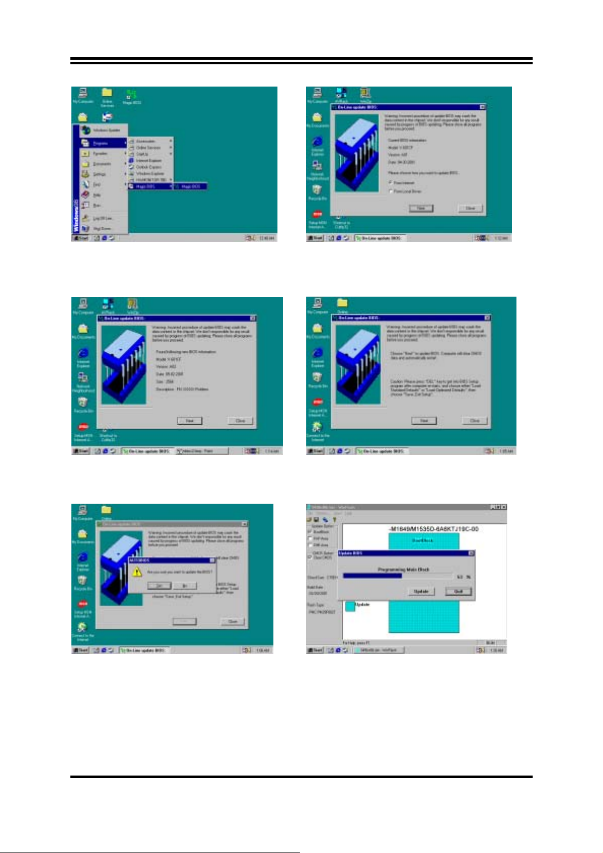
3. After finish Setup you will have a Magic
BIOS icon in your screen
4. Double click the Magic BIOS icon you will
have this picture, choose from internet you
can upgrade BIOS On-line
5. When On-line update BIOS the program
will auto-check your BIOS version
7. Click Yes if you want to update the BIOS
otherwise choose No to exit
6. Click Next if you need update BIOS, after
upgrade BIOS, the system will clear CMOS
and automatically restart
8. When System programming BIOS don’t turn
off power, after finish update BIOS, the
system will clear CMOS and automatically
Restart
43
Page 47
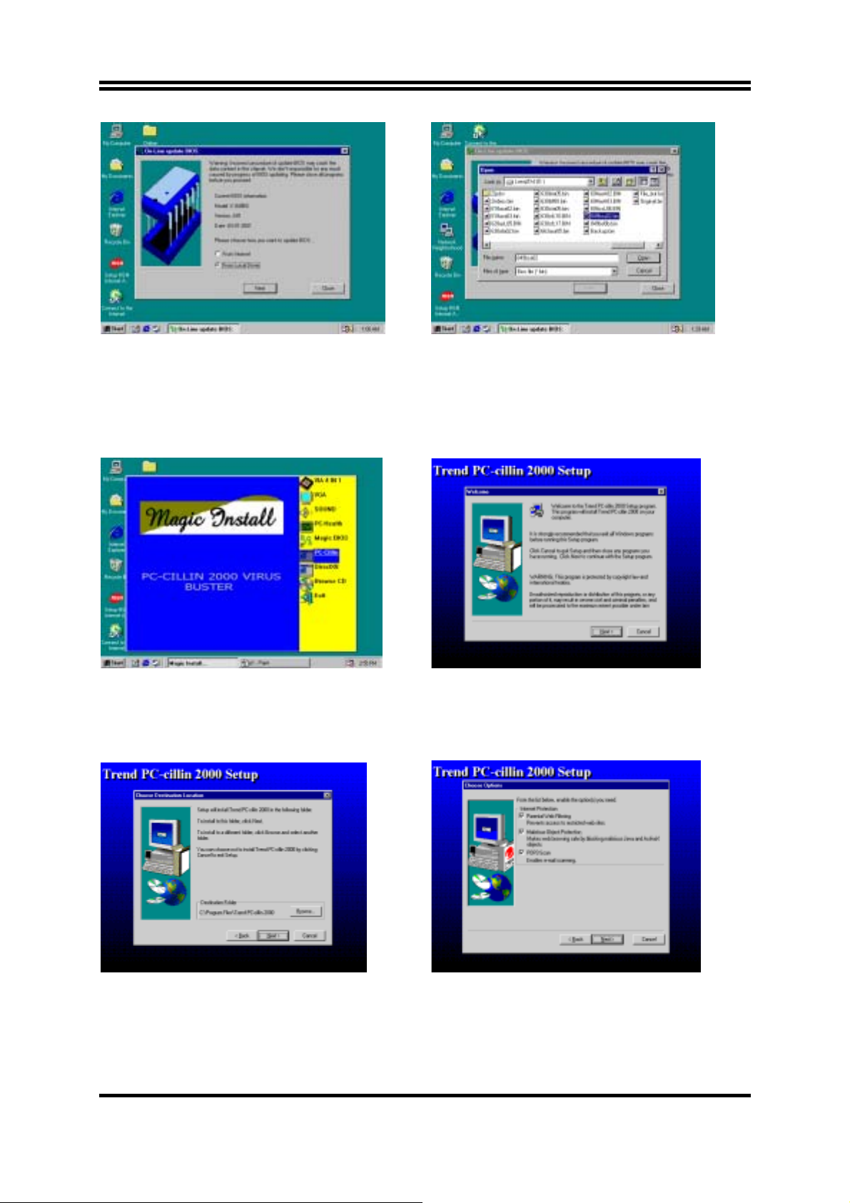
9. When choose From Local Driver to update
BIOS, you must have the correct BIOS file
in your Local Driver
10. Choose the correct BIOS file to update BIOS
4-6 PC-CILLIN Install PC-CILLIN 2000 Anti-virus program
1. Click PC-CILLIN when MAGIC INSTALL
MENU Appears
3. Click NEXT and Enter User Information,
Click NEXT or choose BROWSE to change
the path For the file to be stored
2. Click NEXT when PC-CILIN 2000 SETUP
APPEARS. Then click YES when the
announcement of copyright appears. Software
is starting to detect HD for virus
4. Click NEXT and Choose all Internet
Protection
44
Page 48
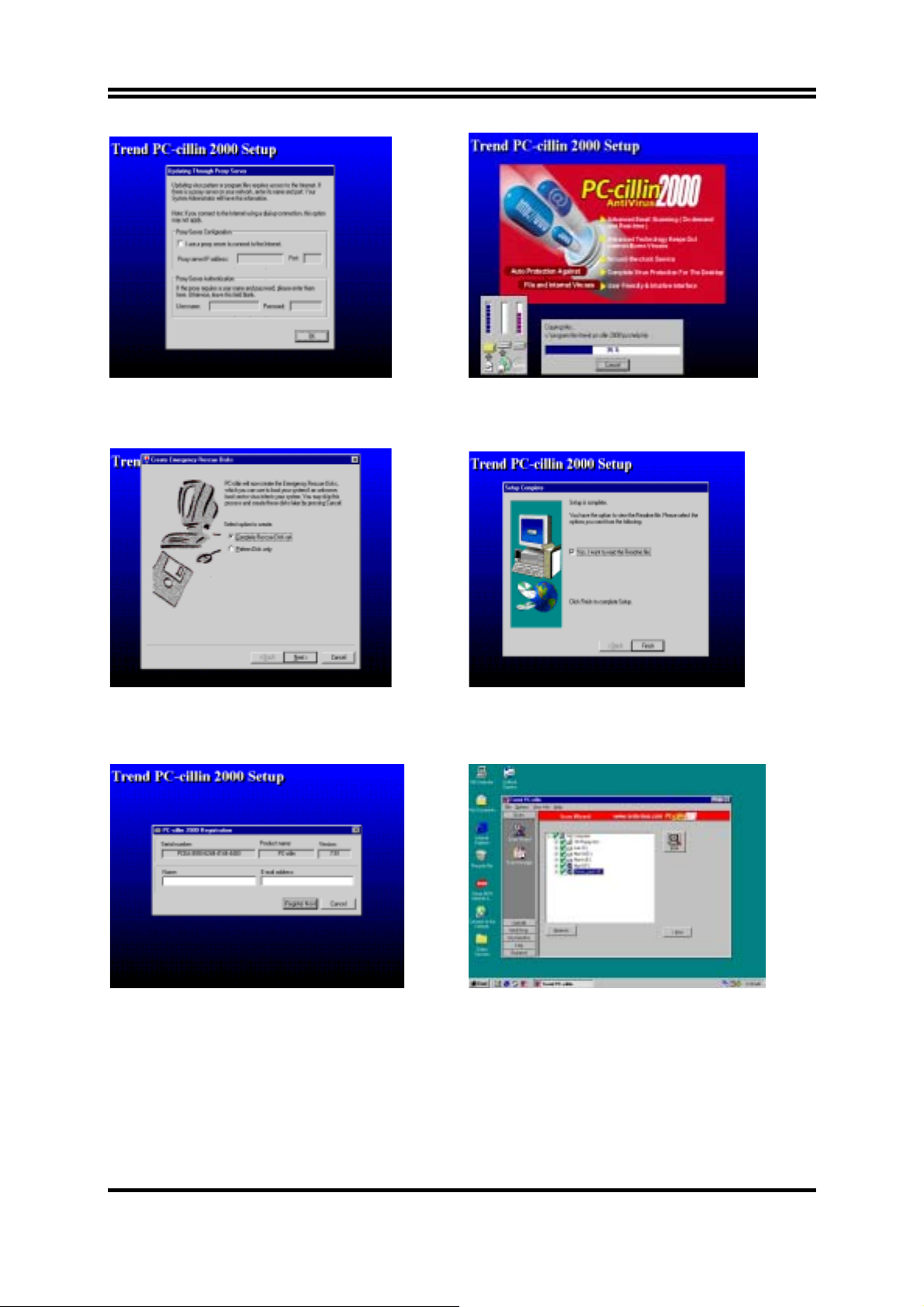
5. Click OK and If You Have Proxy Server,
Enter Your Setting
7. If you want to make a rescue disc, insert a
1.44 MB disc
6. Click NEXT when Start Copy Files, Start to
install the software
8. Setup Complete and click Finish
9. Enter Your name and E-mail address
Register PC-cillin 2000 or Click Cancel
Register Later
10. After install PC-cillin 2000 complete we
recommend select update item to download
newest virus code and setting Auto refresh
virus code
45
Page 49

4-7 HOW TO DISABLE ON-BOARD SOUND
Enter BIOS SETUP choose INTEGRATE PERIPHERALS choose ON-CHIP DEVICE
FUNCTION choose AC97 SOUND DEVICE
Disable on-board sound function by press PAGE DOWN KEY to Disable
4-8 HOW TO UPDATE BIOS
Before update BIOS please choose Disabled in “Flash Part Write Protect” item on
“Miscellaneous Control” in BIOS Setup, please refer page 34
Method 1.
Use “Magic BIOS” update BIOS in Windows 98 (refer page 41)
Method 2.
STEP 1.
In DOS Mode
Prepare a boot disc. (you may make one by click START click RUN type SYS A:
click OK)
STEP 2.
Copy utility program to your boot disc. You may copy from DRIVER CD
X:\FLASH\AWDFLASH.EXE or download from our web site.
STEP 3.
STEP 4.
Copy latest BIOS for P4XFA from our web site to your boot disc.
Insert your boot disc into A:,
start the computer, type “Awdflash A:\P4XFAAxxx.BIN /SN/PY/CC/R”
P4XFAAxxx.BIN is the file name of latest BIOS it can be P4XFAA3.BIN or
P4XFAB2.BIN
SN means don’t save existing BIOS data
PY means renew existing BIOS data
CC means clear existing CMOS data
R means restart computer
STEP 5. Push ENTER and the BIOS will be updated, computer will be restarted
automatically.
46
 Loading...