


P4MBMS
USER'S MANUAL
M/B For LGA775 Pentium 4 Processor
NO. G03-P4MBMS
Rev:1.0
Release date: September 2005
Trademark:
* Specifications and Information contained in this documentation are furnished for information use only , and are
subject to change at any time without notice, and should not be construed as a commitment by manufacturer.

USER’S NOTICE ....................................................................................................................................................ii
MANUAL REVISION INFORMATION ..............................................................................................................ii
COOLING SOLUTIONS........................................................................................................................................ii
CHAPTER 1 INTRODUCTION OF P4MBMS MOTHERBOARD
1-1 FEATURE OF MOTHERBOARD.......................................................................................................1
1-2 SPECIFICATION..................................................................................................................................2
1-3 PERFORMANCE LIST........................................................................................................................3
1-4 LAYOUT DIAGRAM & JUMPER SETTING....................................................................................4
CHAPTER 2 HARDWARE INSTALLATION
2-1 HARDWARE INSTALLATION STEPS .............................................................................................6
2-2 CHECKING MOTHERBOARD'S JUMPER SETTING...................................................................6
2-3 INSTALL CPU.......................................................................................................................................7
2-3-1 GLOSSARY................................................................................................................................7
2-3-2 ABOUT INTEL PENTIUM4 LGA 775 CPU ...........................................................................8
2-3-3 LGA 775 CPU INSTALLATION GUIDE................................................................................9
2-4 INSTALL MEMORY............................................................................................................................18
2-5 EXPANSION CARD..............................................................................................................................19
2-5-1 PROCEDURE FOR EXPANSION CARD INSTALLATION................................................19
2-5-2 ASSIGNING IRQ FOR EXPANSION CARD .........................................................................19
2-5-3 INTERRUPT REQUEST TABLE FOR THIS MOTHERBOARD .......................................20
2-5-4 AGP SLOT.................................................................................................................................. 20
2-6 CONNECTORS, HEADERS.................................................................................................................20
2-6-1 CONNECTORS..........................................................................................................................20
2-6-2 HEADERS...................................................................................................................................24
2-7 STARTING UP YOUR COMPUTER..................................................................................................27
CHAPTER 3 INTRODUCING BIOS
3-1 ENTERING SETUP...............................................................................................................................28
3-2 GETTING HELP...................................................................................................................................28
3-3 THE MAIN MENU................................................................................................................................29
3-4 STANDARD CMOS FEATURES.........................................................................................................30
3-5 ADVANCED BIOS FEATURES ..........................................................................................................31
3-6 ADVANCED CHIPSET FEATURES..................................................................................................
3-6-1 DRAM TIMING SETTINGS....................................................................................................34
3-6-2 AGP TIMING SETTINGS........................................................................................................35
3-6-3 PCI TIMING SETTINGS..........................................................................................................35
3-7 INTEGRATED PERIPHERALS..........................................................................................................36
3-7-1 ONCHIP IDE FUNCTION........................................................................................................36
3-7-2 ONCHIP DEVICE FUNCTION................................................................................................37
3-7-3 ONBOARD SUPER IO FUNCTION........................................................................................38
3-8 POWER MANAGEMENT SETUP......................................................................................................39
3-8-1 WAKE UP EVENTS.................................................................................................................40
3-8-1.1 IRQS ACTIVITIES ................................................................................................... ..............40
3-9 PNP/PCI CONFIGURATION SETUP.................................................................................................41
3-9-1 IRQ RESOURCES ....................................................................................................................42
3-10 PC HEALTH STATUS........................................................................................................................42
3-11 MISCELLANEOUS CONTROL........................................................................................................43
3-12 LOAD STANDARD/OPTIMIZED DEFAULTS ...............................................................................44
3-13 SET SUPERVISOR/USER PASSWORD...........................................................................................45
CHAPTER 4 DRIVER & FREE PROGRAM INSTALLATION
MAGIC INSTALL SUPPORTS WINDOWS 9X/ME/NT4.0/2000/XP .........................................................46
4-1 VIA 4 IN 1 INSTALL VIA SERVICE PACK 4 IN 1 DRIVER............................................47
4-2 VGA INSTALL P4M800CE VGA DRIVER................................................................48
4-3 SOUND INSTALL ALC AUDIO CODEC DRIVER........................................................48
4-4 LAN INSTALL VIA 10/100MB LAN CONTROLLER DRIVER.............................. 49
4-5 PC-HEALTH INSTALL MYGUARD HARDWARE MONITOR UTILITY..........................50
4-6 PC-CILLIN INSTALL PC-CILLIN2005 ANTI-VIRUS PROGRAM...................................51
4-7 USB2.0 INSTALL VIA USB2.0 DEVICE DRIVER........................................................52
4-8 SATA INSTALL VIA SERIAL ATA .................................................................................53
4-9 HOW TO DISABLE ON-BOARD SOUND.........................................................................................54
4-10 HOW TO UPDATE BIOS.....................................................................................................................54
TABLE OF CONTENT
.33
i

USER’S NOTICE
COPYRIGHT OF THIS MANUAL BELONGS TO THE MANUFACTURER. NO PART OF THIS
MANUAL, INCLUDING THE PRODUCTS AND SOFTWARE DESCRIBED IN IT MAY BE
REPRODUCED, TRANSMITTED OR TRANSLATED INTO ANY LANGUAGE IN ANY FORM OR
BY ANY MEANS WITHOUT WRITTEN PERMISSION OF THE MANUFACTURER.
THIS MANUAL CONTAINS ALL INFORMATION REQUIRED TO USE P4MBMS MOTHERBOARD AND WE DO ASSURE THIS MANUAL MEETS USER’S REQUIREMENT BUT WILL
CHANGE, CORRECT ANY TIME WITHOUT NOTICE. MANUFACTURER PROVIDES THIS
MANUAL “AS IS” WITHOUT WARRANTY OF ANY KIND, AND WILL NOT BE LIABLE FOR ANY
INDIRECT, SPECIAL, INCIDENTIAL OR CONSEQUENTIAL DAMAGES (INCLUDING
DAMANGES FOR LOSS OF PROFIT, LOSS OF BUSINESS, LOSS OF USE OF DATA,
INTERRUPTION OF BUSINESS AND THE LIKE).
PRODUCTS AND CORPORATE NAMES APPEARING IN THIS MANUAL MAY OR MAY NOT BE
REGISTERED TRADEMARKS OR COPYRIGHTS OF THEIR RESPECTIVE COMPANIES, AND
THEY ARE USED ONLY FOR IDENTIFICATION OR EXPLANATION AND TO THE OWNER’S
BENEFIT, WITHOUT INTENT TO INFRINGE.
Manual Revision Information
Reversion Revision History Date
1.0 First Edition September 2005
Item Checklist
5
P4MBMS motherboard
5
Cable for IDE/Floppy
5
CD for motherboard utilities
5
Cable for Serial ATA IDE Port
5
P4MBMS User’s Manual
Intel Pentium 4 Processor Family
Cooling Solutions
As processor technology pushes to faster speeds and higher performance, thermal management
becomes increasingly crucial while building computer systems. Maintaining the proper thermal
environment is the key to reliable, long-term system operation. The overall goal in providing the
proper thermal environment is keeping the processor below its specified maximum case temperature.
Heat sinks induce improved processor heat dissipation through increased surface area and
concentrated airflow from attached fans. In addition, interface materials allow effective transfers of
heat from the processor to the heat sink. For optimum heat transfer, Intel recommends the use of
thermal grease and mounting clips to attach the heat sink to the processor.
When selecting a thermal solution for your system, please refer to the website below for collection of
heat sinks evaluated and recommended by Intel for use with Intel processors. Note, those heat sinks
are recommended for maintaining the specified Maximum T case requirement. In addition, this
collection is not intended to be a comprehensive listing of all heat sinks that support Intel processors.
For vendor list of certified heat sinks and cooling fans, please visit :
http://developer.intel.com/design/Pentium4/components/index
ii

Chapter 1
Introduction of P4MBMS Motherboard
1-1 Feature of motherboard
The P4MBMS motherboard is designed for the use of Intel Pentium 4 Processor in LGA775
Package Processor with the VIA P4M800CE Chipset that delivers a high performance and
professional desktop platform solution. It utilizes the LGA 775 design and the memory size
which is expandable to 2.0GB.
These motherboards use the newest VIA P4M800CE chipset, supports 400MHz/ 533MHz
/800MHz System Bus in data transfer rate.
Supports Hyper Threading/ Prescott CPU
motherboards provided 133MHz/166MHz/200MHz Memory clock frequency, support DDR266
/DDR333/DDR400 DDR Module. The motherboard embedded VIA VT8237 V-Link LPC
South Bridge offer ULTRA
functions to provide speedier HDD throughout that boosts overall system performance.
ATA)
ATA 133
and
Serial ATA with RAID 0, 1, 0+1, and JBOD(S-
The P4MBMS used the VIA VT6103 LAN PHY chip Support Fast Ethernet LAN function
provide 10/100 Mb/s data transfer rate.
. The se
The motherboard also has an integrated 6-channel AC’97 CODEC on board which is fully
compatible with Sound Blaster Pro® that gives you the best sound quality and compatibility.
P4MBMS motherboards integrated S3 Graphics UniChrome Pro Integrated Graphics
Processor with high performance & high quality 3D accelerator supports Ultra-AGPII with
2GB/s bandwidth, built-in MPEG-2/1 Video Decoder and Video Accelerator supports VCD
DVD HDTV decoding and playback, supports graphic and video overlay function. Built-in
programmable 24-bit true-color RAMDAC up to 250MHz pixel clock. Programmable frame
buffer size from 16MB and up to 64MB. For those wanting even greater graphic performance.
P4MBMS provides an AGP slot supports AGP 8X/4X capability and Fast write Transaction.
With USB control as well as capability of expanding to 8x USB2.0 function ports delivering
480Mb/s bandwidth and rich connectivity, these motherboards meet future USB demand also
has built-in hardware monitor function to monitor and protect your computer.
A useful software tool “Magic BIOS” examines the BIOS version automatically with the
correct version available on the web, links the site for users to download the latest version of
BIOS and updates the BIOS. Use “Magic BIOS”, users can download and update BIOS
automatically and completed under the OS easily.
These motherboards provide high performance & meets future specification demand. It is
really wise choice for your computer.
1

1-2 Specification
Spec Description
Design
Chipset
CPU Socket
(LGA 775 Socket)
Memory Socket
Expansion Slot
Integrate IDE and
Serial ATA RAID
VGA
LAN
Audio
BIOS
Multi I/O
∗ Micro ATX form factor 4 layers PCB size: 24.4x21.0cm
∗ VIA P4M800CE North Bridge Chipset
∗ VIA VT8237R South Bridge Chipset
∗ Support Intel Pentium 4 775-Land LGA Package utilizes Flip-
Chip Land Grid Array (FCLGA4) package processor
∗ Support CPU Frequency 533MHz/800MHz
∗ Support 2.8G/3.0G/3.6G LGA 775 Pentium 4 processor
∗ Reserves support for future Intel Pentium 4 processors
∗ 184-pin DDR Module socket x 2
∗ Support 2pcs DDR266/DDR33/DDR400 DDR Modules
Expandable to 2.0GB
∗ AGP slot x1 support AGP 2.0 & AGP 3.0 for 4X/8X mode
∗ 32-bit PCI slot x3
∗ Two PCI IDE controllers support PCI Bus Mastering, ATA
PIO/DMA and the ULTRA DMA 33/66/100/133 functions that
deliver the data transfer rate up to 133 MB/s; Two Serial ATA
ports provide 150 MB/sec data transfer rate for two Serial ATA
Devices and offer RAID 0, 1, 0+1, JBOD(S-ATA) functions
∗ Integrated S3 Graphics UniChrome Pro Integrated Graphics
Processor
∗ Support Ultra-AGPII with 2GB/s bandwidth
∗ Built-in programmable 24-bit true-color RAMDAC up to
250MHz pixel clock
∗ Programmable frame buffer size from 16MB and up to 64MB.
∗ Support Fast Ethernet LAN function provide 10/100 Mb/s data
transfer rate
∗ AC’97 Digital Audio controller integrated
∗ 6-channel AC’97 Audio CODEC on board
∗ Audio driver and utility included
∗ Award 4MB Flash ROM
∗ PS/2 keyboard and PS/2 mouse connectors
∗ Floppy disk drive connector x1
∗ Parallel port x1
∗ Serial port x1
∗ USB2.0 port x 4 and headers x 4 (connecting cable option)
∗ Audio connector (Line-in, Line-out, MIC)
2
1-3 Performance List
The following performance data list is the testing result of some popular benchmark
testing programs. These data are just referred by users, and there is no responsibility
for different testing data values gotten by users (the different Hardware & Software
configuration will result in different benchmark testing results.)
Performance Test Report
CPU:
DRAM:
VGA Expansion Card:
Hard Disk Driver:
BIOS:
Windows XP Professional (SERVICE PACK 1)
OS:
P4M800CE
3D Mark 2001SE 2065
3D Mark 2003 122
3D Winbench 2000 (32/32bit) 47.6
PC Mark 2002 CPU/Memory/HDD 7294 / 5915 / 845
PCMark2004
System/CPU/Memory/Graph/HDD 3469/4362/3323/605/3269
Content Creation Winstone 2002 44.6
Content Creation Winstone 2003 48.5
Business Winstone 2002 31.9
Content Creation Winstone 2004 26.1
Business Winstone 2004 21.6
Winbench 99 V1.2:
Business/Hi-end Disk Winmark99 9190 / 32800
Business/Hi-end Graphic Winmark 366 / 1000
SYS Mark 2001/2002 : SISMark 2001/2002 Rating (Internet Content
Creation / Office Productivity)
SISMark 2001 265 (307 / 229)
SISMark 2002 301 (413 / 200)
SISOFT Sandra 2003 :
Dhrystone ALU MIPS 8860
Whetstone FPU MFLOPS 2588 / 5793
RAM Int Buffered iSSE2 MB/S 2829
RAM Float Buffered iSSE2 MB/S 2826
Integer SSE2 IT/S 13813
Floating- Point SSE2 IT/S 22051
QUAKE3 DEMO1/DEMO2 FPS 69.0 / 65.2
Return to Castle Wolfenstein FPS 61.6
Super Pi (1M) Second 54s
WCPUID System/CPU Clock 200.04 / 3000.54
Intel Pentium4 3GHz (FSB 800) Hyper-Threading Support
KINGSTON D328DW 512M DDR400 X 2 PCS Total 1Gbyte Memory
ON BOARD VGA (1024X768X32BIT Color)
IBM IC35L040AVVN07-0 (ATA-100 7200RPM)
Award Optimal default
3
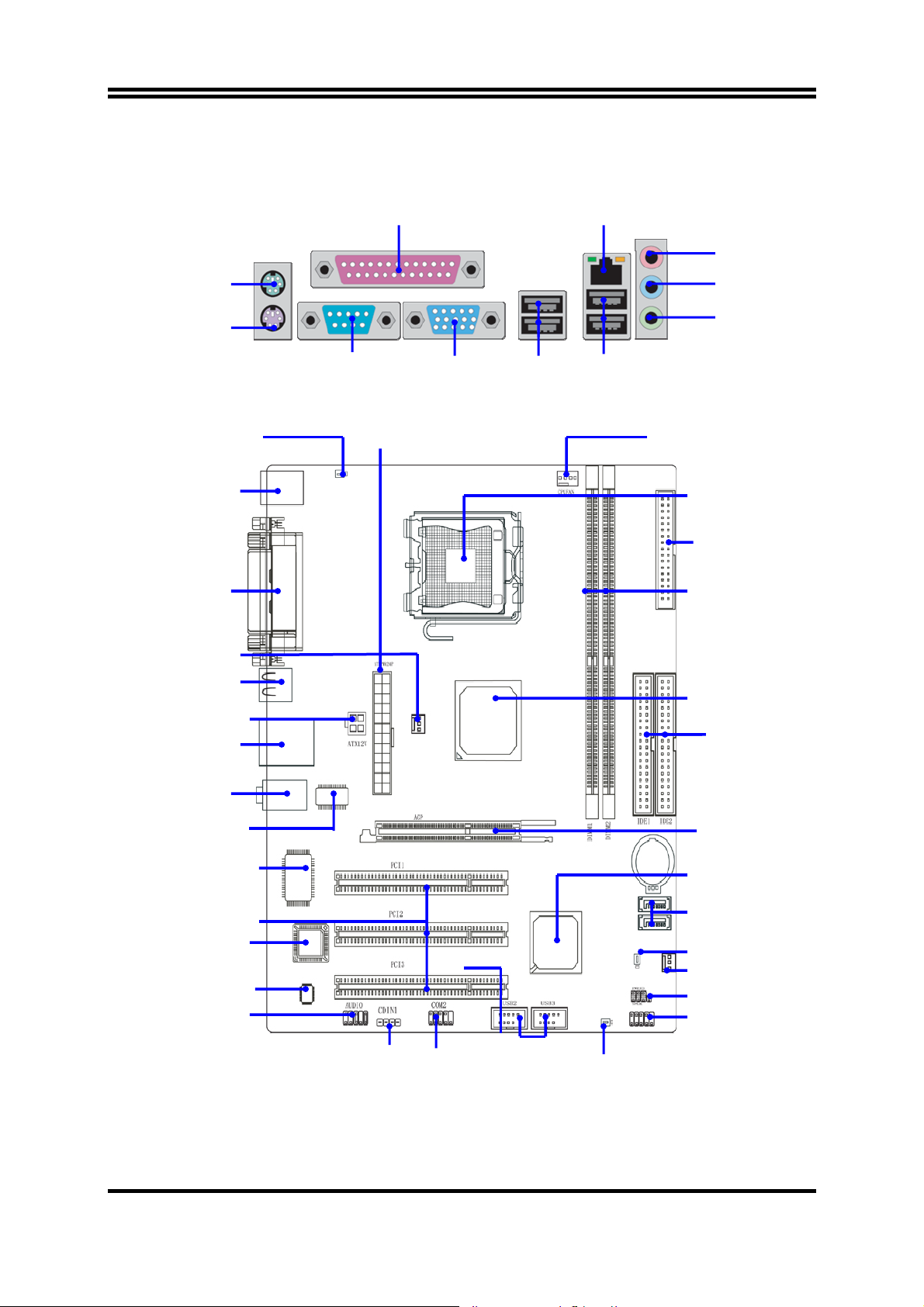
1-4 Layout Diagram & Jumper Setting
PRINT
RJ45
LAN
MIC
PS/2 Mouse
PS/2 Keyboard
K/B Power
ON Jumper (JP1)
PS2 KB/Mouse Port
PC99 Back Panel
SFAN1
USB Port
ATX 12V Connector
USB Port/
LAN Connector
COM1
ATX Power Connector
VGA
LINE-IN
LINE-OUT
USB1
USBLAN
CPU FAN
CPU Socket
Floppy
Connector
DDR Socket X2
VIA P4M800CE
Chipset
ATA 133 IDE
Connector (IDE1, IDE2)
Audio Connector
VIA VT6103
LAN PHY
ITE IT8705F Chip
PCI Slot
4MBit Flash ROM BIOS
6-CH AC’97
Audio Codec
Front Panel Audio
CD Audio
COM2
Connector
4
USB Port
(USB2, USB3)
USB Power
On Jumper (JP4)
AGP Slot
VIA VT8237R Chip
Serial-ATA
Connector (SATA1, 2)
Clear CMOS (JBAT)
SFAN2
Speaker / Power LED Connector
Front Panel Connector
Jumpers
Jumper Name Description Page
JBAT
JP1
JP4
CMOS RAM Clear
Keyboard Power On Enable/Disabled
USB Power On Enable/Disabled
3-pin Block P.6
3-pin Block P.7
3-pin Block P.7
Connectors
Connector Name Description Page
ATXPWR Power Connector 24-pin Block P.20
ATX12V ATX 12V Power Connector 4-pin Block P.21
PS2KBMS PS/2 Mouse & PS/2 Keyboard
Connector
USB1 USB Port Connector 4-pin Connector P.22
USBLAN LAN Port Connector RJ-45 Connector P.22
PARALLEL Parallel Port Connector 25-pin Female P.22
AUDIO Audio Connector 3 phone jack Connector P.22
COM1 Serial Port COM1 Connector 9-pin Connector P.22
VGA VGA Connector
FDD Floppy Driver Connector 34-pin Block P.22
IDE1/IDE2 Primary/Secondary IDE Connector 40-pin Block P.23
6-pin Female P.22
15-pin Female
P.22
Headers
Header Name Description Page
AUDIO MIC header 9-pin Block P.24
USB2, USB3 USB Port Headers 9-pin Block P.25
HD LED IDE activity LED 2-pin Block P.25
RESET Reset switch lead 2-pin Block P.25
SPEAK PC Speaker connector 4-pin Block P.25
PWR LED Power LED 2-pin Block P.25
PWR BTN Power switch 2-pin Block P.25
SFAN1, SFAN2
CPUFAN
COM2 Serial Port COM2 Connector 9-pin Block P.26
CD_IN CD Audio-In Headers 4-pin Block P.26
Expansion Sockets
Socket/Slot Name Description Page
LGA 775 Socket CPU Socket LGA 775 CPU Socket
DDR1, DDR2 DDR Module Socket 184-pin DDR Module Socket P.18
PCI1, PCI2, PCI3 PCI Slot 32-bit PCI Local Bus Expansion slots P.20
AGP AGP 4X/8X Mode Slot AGP Expansion Slot P.20
FAN Headers 3-pin Block P.26
P.8
5
Chapter 2
Hardware installation
2-1 Hardware installation Steps
Before using your computer, you had better complete the following steps:
1. Check motherboard jumper setting
2. Install CPU and Fan
3. Install System Memory (DIMM)
4. Install Expansion cards
5. Connect IDE and Floppy cables, Front Panel /Back Panel cable
6. Connect ATX Power cable
7. Power-On and Load Standard Default
8. Reboot
9. Install Operating System
10. Install Driver and Utility
2-2 Checking Motherboard’s Jumper Setting
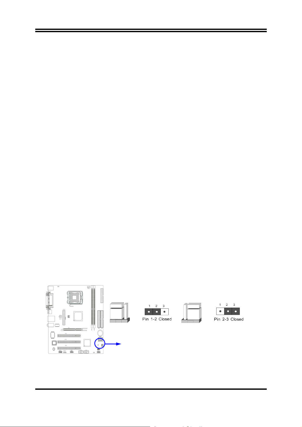
(1) CMOS RAM Clear (3-pin) : JBAT
A battery must be used to retain the motherboard configuration in CMOS RAM short 1-2
pins of JBAT to store the CMOS data.
To clear the CMOS, follow the procedure below:
1. Turn off the system and unplug the AC power
2. Remove ATX power cable from ATX power connector
3. Locate JBAT and short pins 2-3 for a few seconds
4. Return JBAT to its normal setting by shorting pins 1-2
5. Connect ATX power cable back to ATX power connector
Note: When should clear CMOS
1. Troubleshooting
2. Forget password
3. After over clocking system boot fail
JBATJBAT
1-2 Closed Normal
CMOS RAM Clear Setting
2-3 Closed Clear CMOS
6
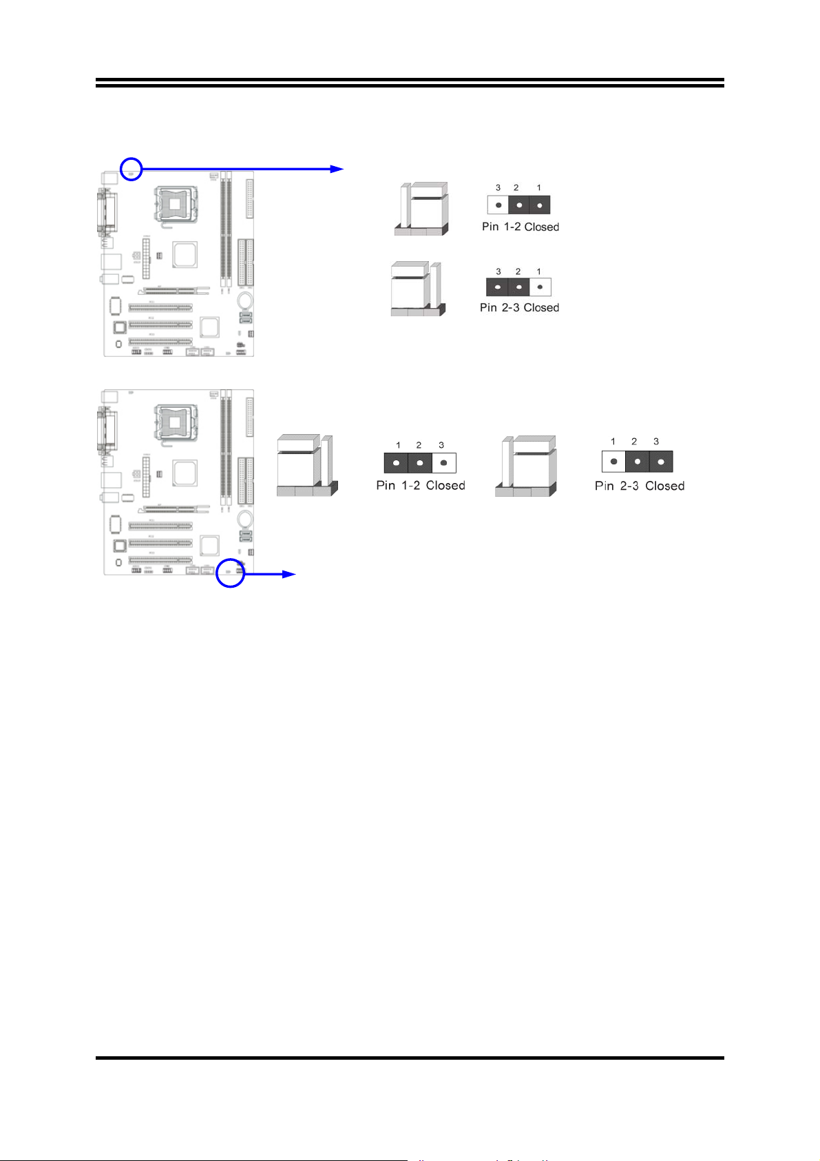
(2) Keyboard function Enabled/Disabled: JP1
JP1
1-2 Closed KB/USB Power ON Disable (Default)
JP1
2-3 Closed KB/USB Power ON Enabled
Keyboard/Mouse Power On Setting
(3) USB Power On function Enabled/Disabled: JP4
JP4 JP4
1-2 closed USB Power On Disable
(Default)
USB Power On Setti ng
2-3 closed USB P o wer On Enabled
2-3 Install CPU
2-3-1 Glossary
Chipset (or core logic) - two or more integrated circuits which control the interfaces between
the system processor, RAM, I/O devises, and adapter cards.
Processor slot/socket - the slot or socket used to mount the system processor on the
motherboard.
Slot (AGP, PCI, ISA, RAM) - the slots used to mount adapter cards and system RAM.
AGP - Accelerated Graphics Port - a high speed interface for video cards; runs at 1X
(66MHz), 2X (133MHz), or 4X (266MHz),
or 8X (533MHz)
PCI - Peripheral Component Interconnect - a high speed interface for video cards, sound
cards, network interface cards, and modems; runs at 33MHz.
ISA - Industry Standard Architecture - a relatively low speed interface primarily used for
sound cards and modems; runs at approx. 8MHz.
Serial Port - a low speed interface typically used for mouse and external modems.
Parallel Port - a low speed interface typically used for printers.
PS/2 - a low speed interface used for mouse and keyboards.
7
USB - Universal Serial Bus - a medium speed interface typically used for mouse, keyboards,
scanners, and some digital cameras.
Sound (interface) - the interface between the sound card or integrated sound connectors and
speakers, MIC, game controllers, and MIDI sound devices.
LAN (interface) - Local Area Network - the interface to your local area network.
BIOS (Basic Input/Output System) - the program logic used to boot up a computer and
establish the relationship between the various components.
Driver - software, which defines the characteristics of a device for use by another device or
other software.
Processor - the "central processing unit" (CPU); the principal integrated circuit used for
doing the "computing" in "personal computer"
Front Side Bus Frequency -
the working frequency of the motherboard, which is generated
by the clock generator for CPU, DRAM and PCI BUS.
CPU L2 Cache -
the flash memory inside the CPU, normal it depend on CPU type.
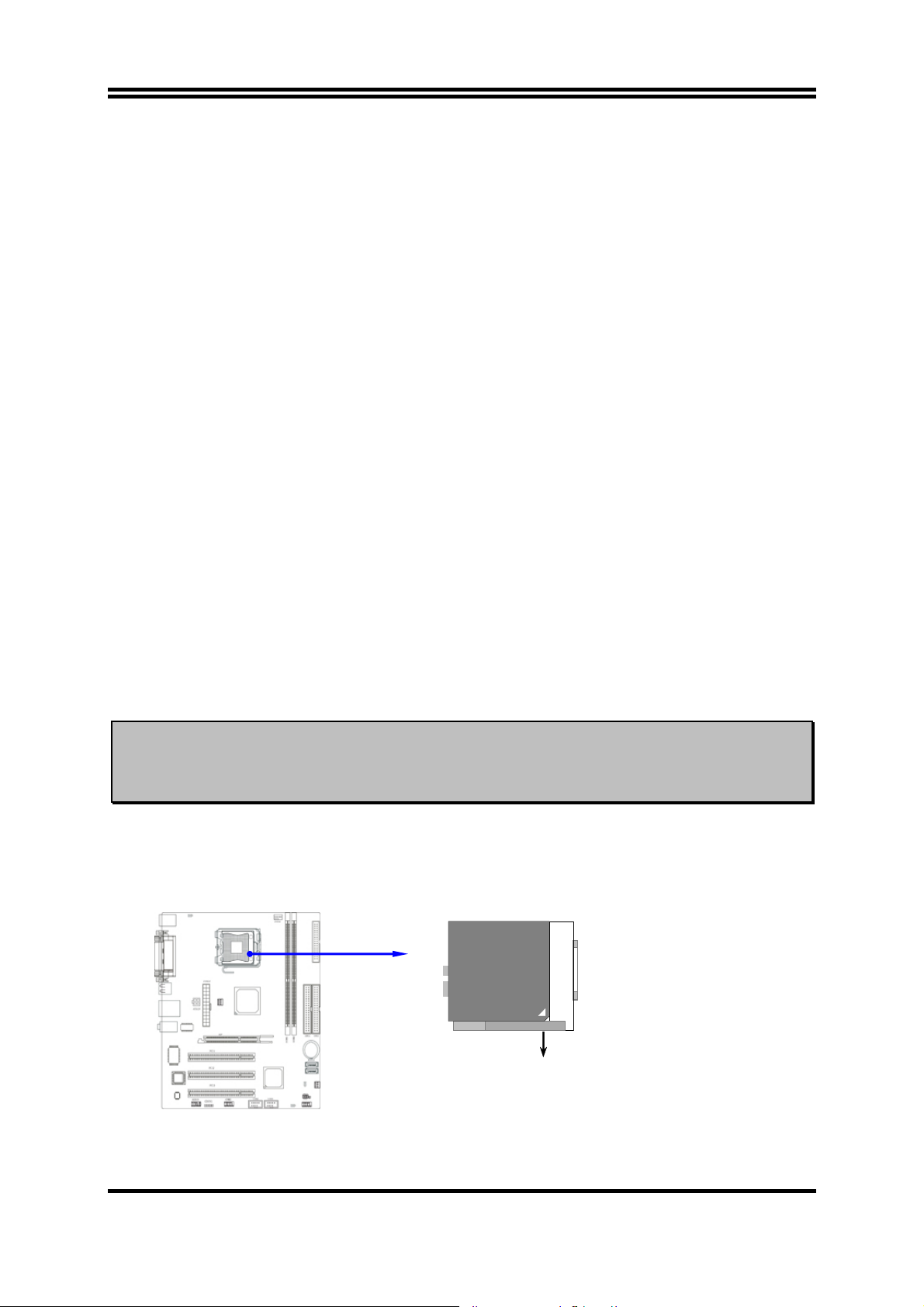
2-3-2 About Intel Pentium 4 LGA775 CPU
This motherboard provides a 775-pin surface mount, LGA775 Land Grid Array socket, referred to as
the LGA775 socket supports Intel Pentium 4 processor in the 775 Pin package utilizes Flip-Chip Land
Grid Array (FC-LGA4) package technology.
The CPU that comes with the motherboard should have a cooling FAN attached to prevent
overheating. If this is not the case, then purchase a correct cooling FAN before you turn on your
system.
WARNING!
To install a CPU, first turn off your system and remove its cover. Locate the LGA775 socket and
open it by first pulling the level sideways away from the socket then upward to a 90-degree angle.
Insert the CPU with the correct orientation as shown below. The notched corner should point toward
the end of the level. Because the CPU has a corner pin for two of the four corners, the CPU will only
fit in the orientation as shown
Be sure that there is sufficient air circulation across the processor’s heatsink and CPU
cooling FAN is working correctly, otherwise it may cause the processor and motherboard
overheat and damage, you may install an auxiliary cooling FAN, if necessary.
.
LGA775
Colden Arrow
CPU LGA775 Socket
When you put the CPU into the LGA775 socket. No force require to insert of the CPU, then
press the level to Locate position slightly without any extra force.
8
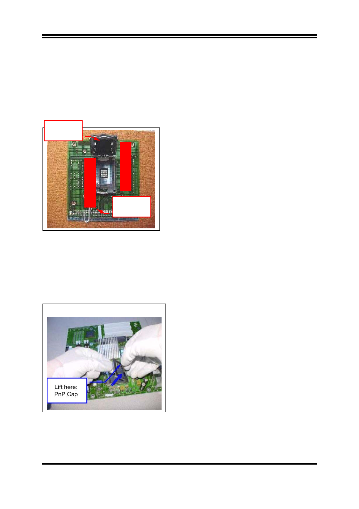
2-3-3 LGA 775 CPU Installation Guide
Socket Preparation
1. Opening the socket:
Note: Apply pressure to the corner with right hand thumb while opening/closing the load lever,
otherwise lever can bounce back like a “mouse trap” and WILL cause bent contacts (when
loaded)
Socket Load
Plate Open
i. Disengage Load Lever by depressing down and
out on the hook to clear retention tab
ii. Rotate Load Lever to fully open position at
approximately 135degrees
iii. Rotate Load Plate to fully open position at
Socket Load
Lever Open
approximately 100degrees
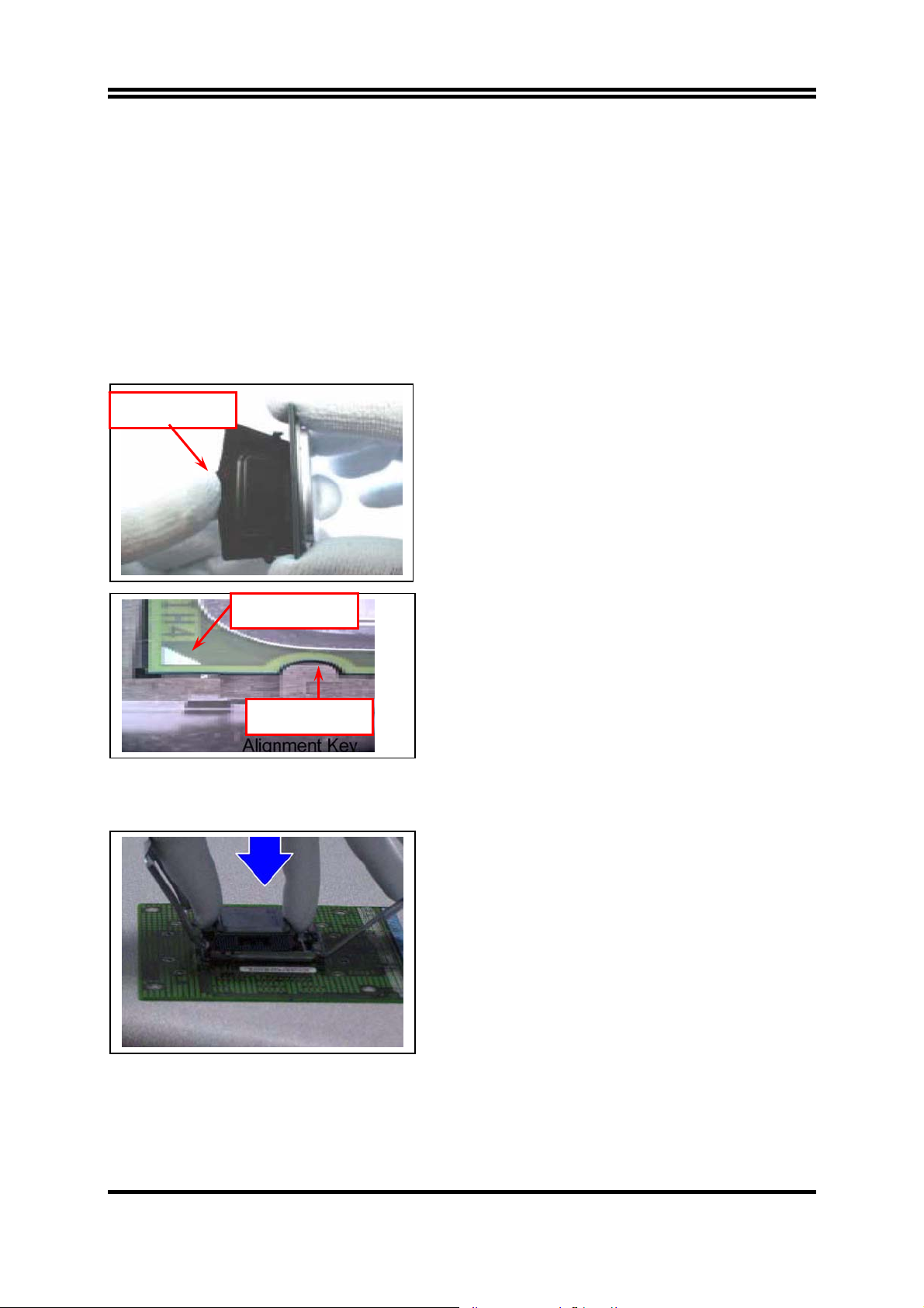
2. Remove PnP Cap (Pick & Place Cap)
i. With left hand index finger and thumb to support the load plate edge, engage PnP cap with right
hand thumb and peel the cap from LGA775 Socket while pressing on center of PnP cap to assist in
removal.
ii. Set PnP cap aside. Always put PnP cap back on if the processor is removed from the socket.
iii. Visually inspect PnP cap for damage. If damage observed, replace the PnP cap.
Note: After PnP cap removal, make sure
socket load plate and contacts are free of
foreign material; Refer to Overview Module for
FM cleaning.
Note: Optionally, remove PnP cap after CPU insertion.
This will compromise the ability to visually
inspect socket.
9
3. Visually inspect for bent contacts (Recommend at least 1stpass visual inspection)
NOTE: Refer to the Handling and Inspection Module for 1stand 2ndpass inspection details.
NOTE: Glove images are for illustrative purposes only. Please consult local safety guidelines for
specific requirements
NOTE: Recommend not to hold the load plate as a lever, instead hold at tab with left hand, removing
the PnP cap with right hand
775-land LGA Package Insertion
Press to remove
Pin 1 Indicator
Alignment Key
1. Lift processor package from shipping media by
grasping the substrate edges ONLY.
Note: Orient processor package such that the Pin 1
triangle mark is on bottom left and both key
notches are on left side
2. Land Side Cover Handling: Remove land side cover
with the opposite hand by depressing larger
retention tab and peeling the cover away
3. Set and reserve the land side cover aside.
Note: Always keep the land side cover on the
processor when not in the socket.
4. Visually inspect the package gold pads: Scan the
processor package gold pad array for presence of
foreign material. Refer to Overview Module for FM
cleaning recommendations
5. Orient the package with IHS up. Locate Pin 1 and
the two orientation key notches
6. Carefully place the package into the socket body
using a purely vertical motion
CAUTION: Using Vacuum Pen for installation is not recommended
7. Verify that package is within the socket body and
properly mated to the orient keys
8. Close the socket by
i. Rotating the Load Plate onto the package HIS
ii. While pressing down lightly on Load Plate, engage
the Load Lever.
iii. Securing Load Lever with Load Plate tab under
retention tab of Load Lever
10
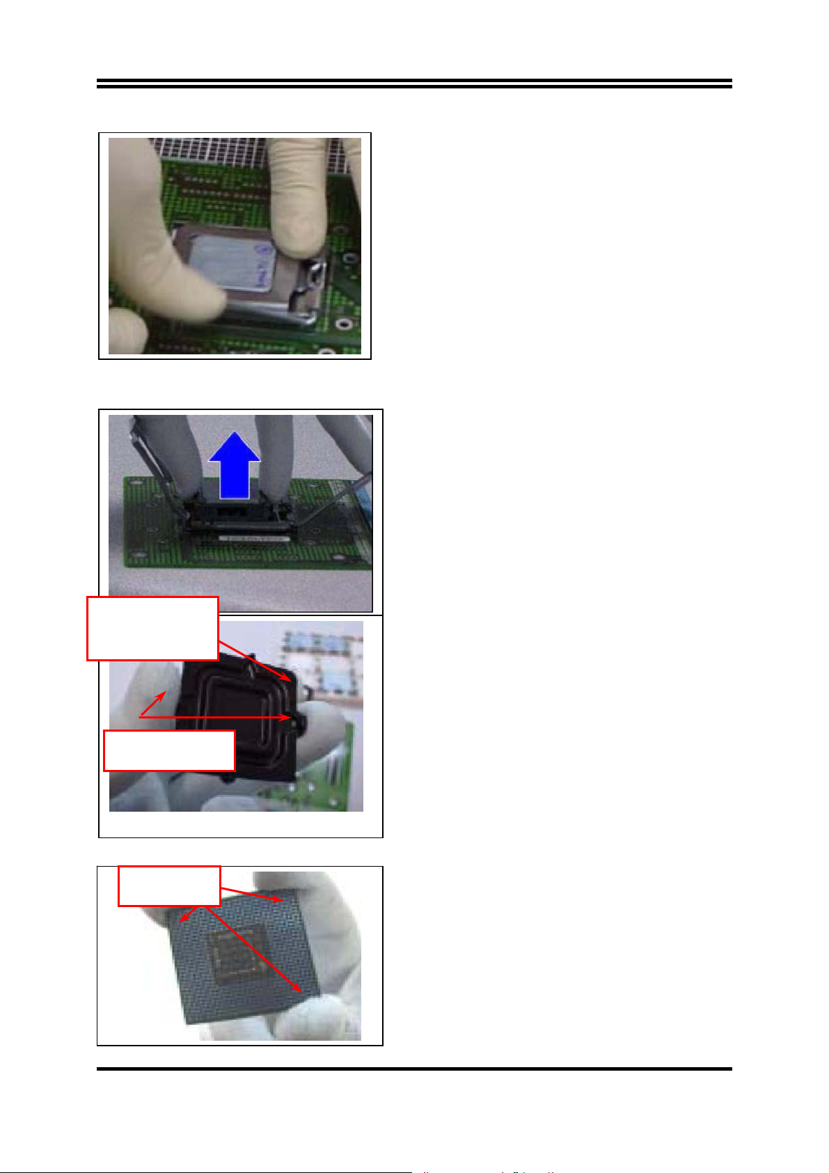
775-Land Package Removal
1. Open the Load Plate/Lever with both hands:
With left hand index finger and thumb to support
the load plate edge, engage PnP cap with right hand
thumb and peel the cap from LGA775 Socket while
pressing on center of PnP cap to assist in removal.
2. Pick up 775-land LGA package:
By Vacuum Pen: Place a minimum 9-mm cup at
approximately the center of IHS.
Recommend not to place Vacuum Pen on IHS edge.
Risk of dropping and causing bent contact.
Recommend not to use Vacuum Pen for inserting
CPU By Hand: Index finger to hold load plate hinge
Chamfer on Land Side
Cover (align this with
pin 1 mark on 775-land
LGA package)
Large Retention Tabs
(pointing towards user)
onto
Hold at corners
side and thumb to hold load lever side
3. Lift the package straight up and away.
4. Assemble processors land side cover immediately
to prevent contamination.
i. While holding the processor by the 3 corners, the
other hand lift land side cover from work surface
by grasping at the large retention tabs. Ensure
retention tabs and package are pointing each
other.
ii. Orientate so that land side cover chamfer is
matching with package Pin 1 location.
iii. Hook the first large retention tab on the package
substrate. Then press the opposite tab onto the
substrate.
iv. Place processor with land side cover installed
proper shipping media or other ESD approved
work surface
11
r
5. Visually inspect socket contact array
1. First Pass Inspection
i. Scan socket contact array at varying angles noting the presence of any foreign material
ii. If foreign material can’t be blown off by compressed air, or mechanical damage (Mode1 or 4)
observed, reject the motherboard for further evaluation or socket replacement.
2. Second Pass Inspection
i. Repeat 2 more times to sight down the rows and columns from each of the 4 sides of the socket to
ensure all contacts within the array are inspected
ii. Inspect for Mode2, Mode3, and Mode5 failures
Note: Refer to the Test Module for detail visual inspections
6. Assemble LGA775 socket PnP cap
i. Secure/Hook the back side of PnP cap.
ii. Snap down the front side to fully secure
7. Close the Socket
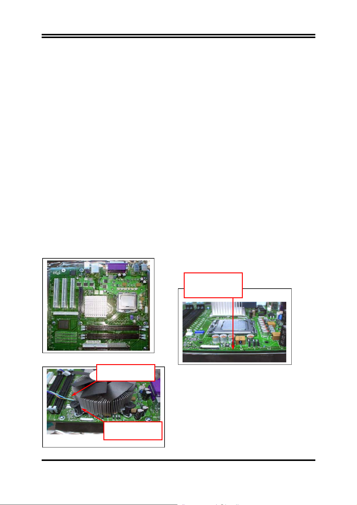
Intel Reference Thermal Solution Assembly
NOTE: Depending on the configuration, Thermal Solution Integration procedure could perform with
M/B alone or with M/B in the Chassis.
Fan cabled on side
closest to MB heade
0.150-inch backside
clearance for fastener
installation
1. Place motherboard on support structure providing
minimum 0.150-inch backside clearance
2. Apply 300 mg of Thermal Interface Material (Shin-
Fastener slots
pointing straight out
Etsu G751) onto center of IHS
12
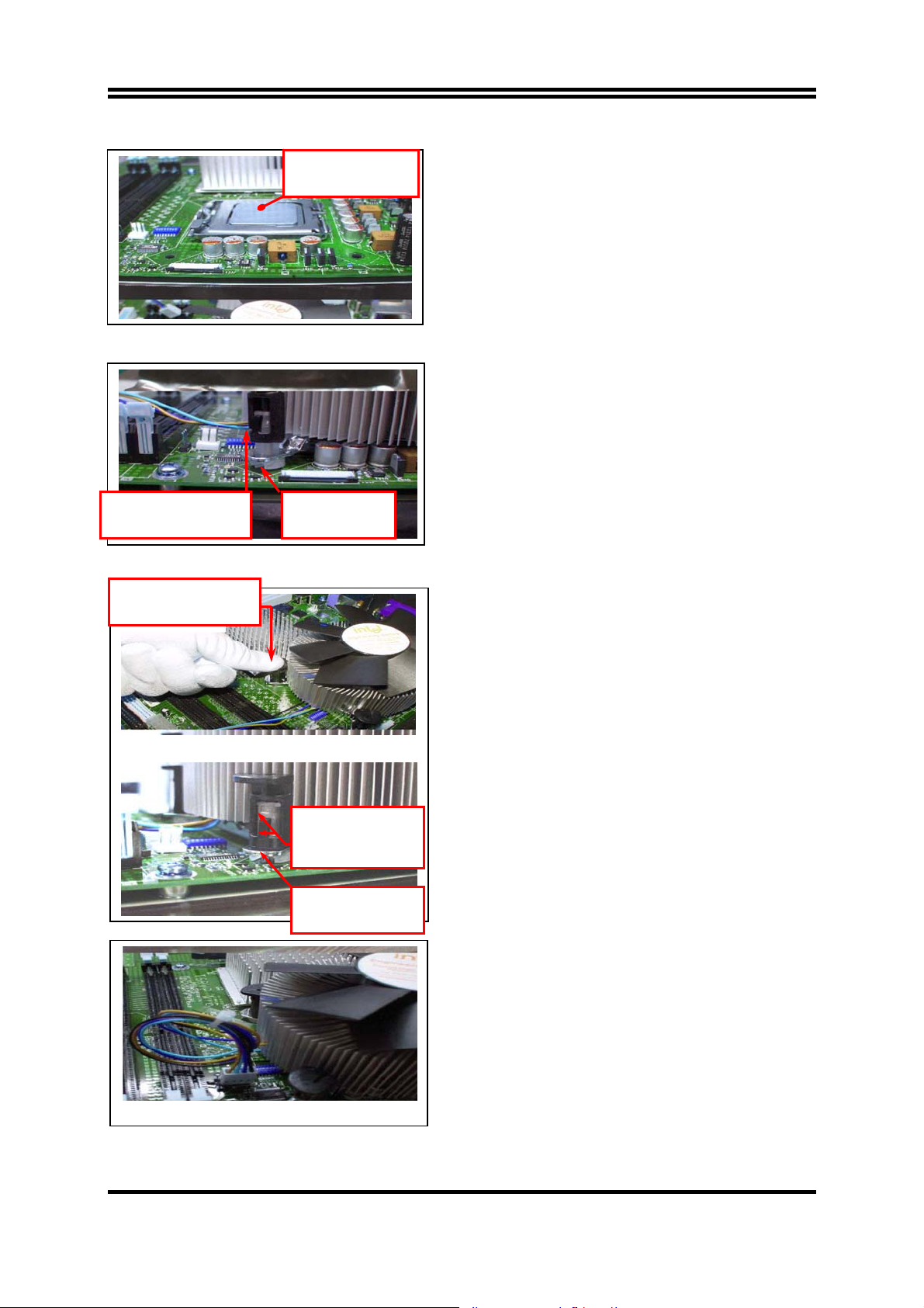
NOTE: Thermal Solutions that come with IntelR boxed
Apply Thermal
Interface Material
processor use pre-applied thermal interface material
and not grease.
3. Remove Heat Sink (HS) from packaging media
4. Place HS onto the LGA775 Socket
• Ensure fan cables are oriented on side closest to
fan header
• Align Fasteners with MB through-holes
5. Inspection
• Ensure cables are not trapped or interfere
fastener operation
• Ensure fastener slots are pointing straight out
from heatsink
Fastener Cap not
resting against spring
Press Down
(4 Places)
Fastener flush
against MB
Both fastener
halves are flush
against spring
Fastener flush
against spring
6. Actuate fasteners
• While holding HS to prevent tilting, press down on
fastener caps with thumb to install and lock
Repeat with remaining fasteners
7. Inspection
• Verify the fasteners are properly seated
• Ensure both fastener cap and base are flush with
spring and motherboard
8. Connect fan header with Board header
9. Secure excess cable with tie-wrap to ensure
cable does not interfere with fan operation or
contact other components.
13
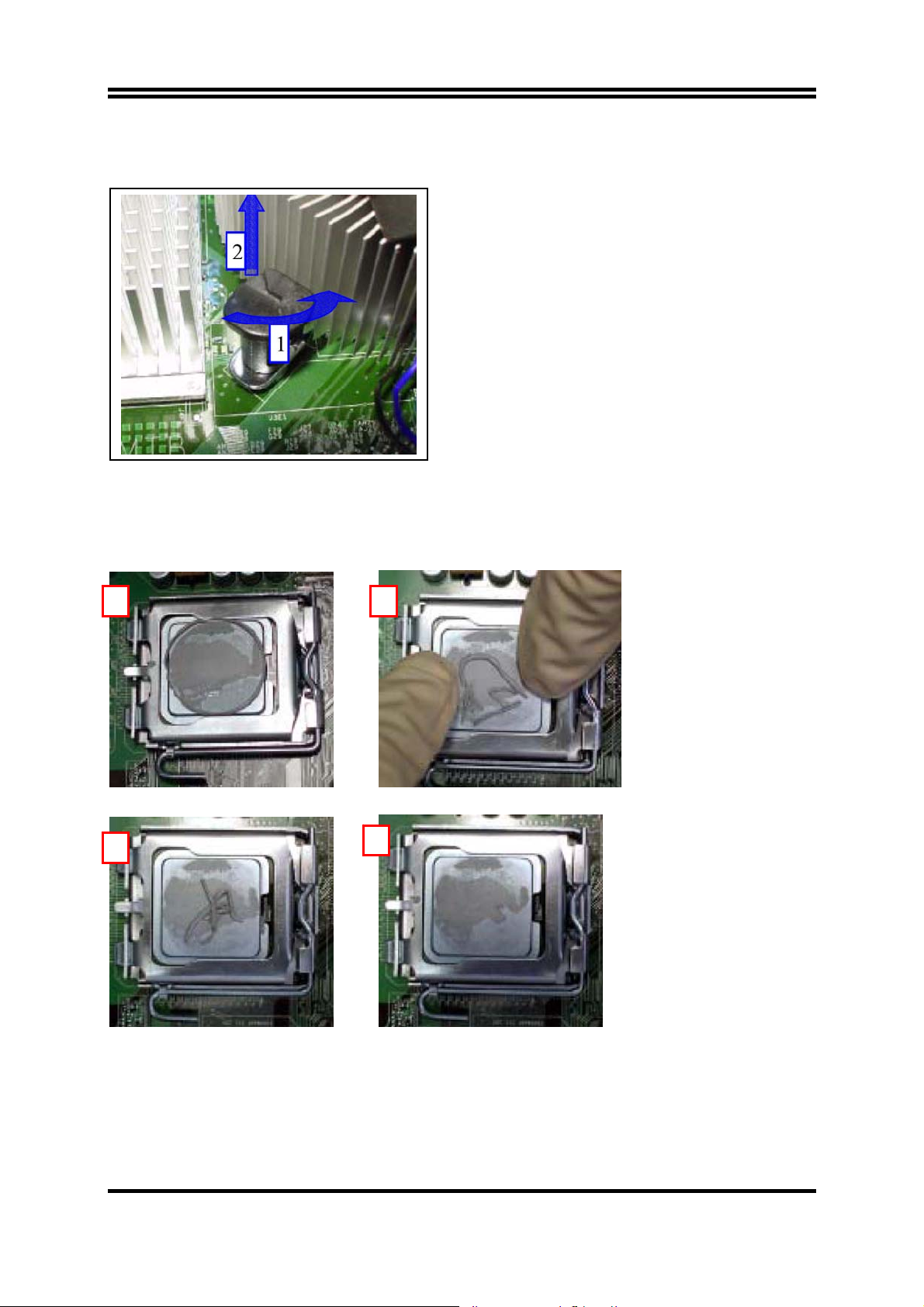
Intel Reference Thermal Solution Disassembly
1. Rotate fastener cap. turn to un-lock
2. Pull up fastener cap to un-seat 12
1. Disconnect fan cable from motherboard header
2. Turn fastener caps (4) counter-clock wise
90degrees to the un-locked position
• A flat-bladed screwdriver may be used if required
3. Pull up on fastener caps to unseat
4. Manually remove HS with gentle twist motion.
5. To re-assemble the HS, reset the fastener caps to
their original position with the slot perpendicular
to the HS. Then, follow the assembly instructions.
Note: Thermal grease should be reapplied
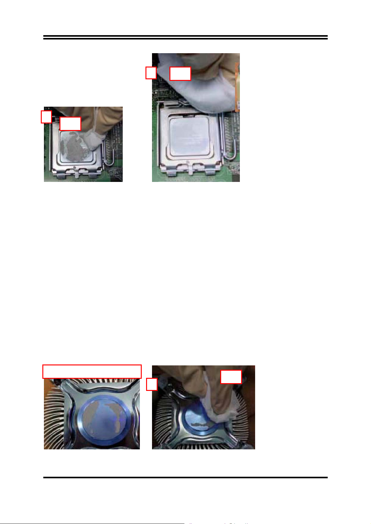
TIM and Grease Removal from CPU
1 2
3
4
14
A
y
6
IP
5
Dry
1. Remove the heatsink from the socket
2. Gently push loose thermal interface material (TIM) to center of processor (pictures 2 and 3)
3. Remove pieces with dry cloth (picture 4)
4. Wipe with dry, lint-free cloth to remove most of the material (picture 5)
5. Wet another lint-free cloth with isopropyl alcohol (IPA) and wipe to clean remaining material
(picture 6)
6. Be careful to remove material from gaps between processor and load plate
7. For thermal grease removal use Step 4-6
TIM and Grease Removal from Heat-sink
Note: Remove and replace the TIM from the heatsink if you are re-using the heatsink on a new
processor
1. Use dry, lint-free cloth and wipe package to remove most of the material
2. Wet another lint-free cloth with isopropyl alcohol (IPA) and wipe heatsink to clean remaining
material
Removal TIM from heatsink
1
Dr
15
 Loading...