

Page 1

TECHNICAL MANUAL
Of
Intel H55 / H57 Express Chipset
Based
Mini-ITX M/B for LGA 1156 Processors
NO.G03-NC97-F
Revision: 1.0
Release date: July, 2010
Trademark:
* Specifications and Information contained in this docume ntation ar e furnishe d for inf ormation us e only , and ar e
subject to change at any time without notice, and should not be construed as a commitment by manufacturer.
Page 2

i
Environmental Protection Announcement
Do not dispose this electronic device into the trash while discarding. To minimize
pollution and ensure environment protection of mother earth, please recycle.
Page 3

ii
ENVIRONMENTAL SAFETY INSTRUCTION...........................................................................iii
USER’S NOTICE .......................................................................................................................iv
MANUAL REVISION INFORMATION.......................................................................................iv
ITEM CHECKLIST.....................................................................................................................iv
CHAPTER 1 INTRODUCTION OF THE MOTHERBOARD
1-1 FEATURE OF MOTHERBOARD................................................................................1
1-2 SPECIFICATION.........................................................................................................2
1-3 LAYOUT DIAGRAM....................................................................................................3
CHAPTER 2 HARDWARE INSTALLATION
2-1 JUMPER SETTING.....................................................................................................7
2-2 CONNECTORS AND HEADERS................................................................................9
2-2-1 CONNECTORS .............................................................................................9
2-2-2 HEADERS .....................................................................................................10
CHAPTER 3 INTRODUCING BIOS
3-1 ENTERNING SETUP...................................................................................................16
3-2 GETTING HELP ..........................................................................................................16
3-3 THE MAIN MENU........................................................................................................16
3-4 STANDARD BIOS FEATURES ..................................................................................18
3-5 ADVANCED BIOS FEATURES..................................................................................21
3-5-1 CPU FEATURE...............................................................................................22
3-6 ADVANCED CHIPSET FEATURES...........................................................................24
3-7 INTEGRATED PHERIPHRALS ..................................................................................25
3-7-1 ONBOARD VGA FUNCTION ..........................................................................26
3-7-2 ONBOARD SATA FUNCTION ........................................................................27
3-7-3 ONBOARD DEVICE FUNCTION.....................................................................28
3-7-3 ONBOARD SUPER IO FUNCTION.................................................................29
3-8 POWER MANAGEMENT SETUP...............................................................................30
3-9 PNP/PCI CONFIGURATIONS.....................................................................................31
3-10 PC HEALTH STATUS.................................................................................................32
3-10-1 SMART FAN CONFIGURATIONS...................................................................33
3-11 MISCELLANEOUS CONTROL...................................................................................34
3-12 PASSWORD SETTING...............................................................................................35
3-13 LOAD OPTIMAL /STANDARD DEFAULTS...............................................................36
TABLE OF CONTENT
Page 4

iii
3-14 SAVE CHAGNES AND EXIT /DISCARD CHANGES AND EXIT ..............................36
Environmental Safety Instruction
z Avoid the dusty, humidity and temperature extremes. Do not place the product in
any area where it may become wet.
z 0 to 60 centigrade is the suitable temperature. (The figure comes from the request
of the main chipset)
z Generally speaking, dramatic changes in temperature may lead to contact
malfunction and crackles due to constant thermal expansion and contraction from
the welding spots’ that connect components and PCB. Computer should go
through an adaptive phase before it boots when it is moved from a cold
environment to a warmer one to avoid condensation phenomenon. These water
drops attached on PCB or the surface of the components can bring about
phenomena as minor as computer instability resulted from corrosion and oxidation
from components and PCB or as major as short circuit that can burn the
components. Suggest starting the computer until the temperature goes up.
z The increasing temperature of the capacitor may decrease the life of computer.
Using the close case may decrease the life of other device because the higher
temperature in the inner of the case.
z Attention to the heat sink when you over-clocking. The higher temperature may
decrease the life of the device and burned the capacitor.
Page 5

iv
USER’S NOTICE
COPYRIGHT OF THIS MANUAL BELONGS TO THE MANUFACTURER. NO PART OF THIS MANUAL,
INCLUDING THE PRODUCTS AND SOFTWARE DESCRIBED IN IT MAY BE REPRODUCED, TRANSMITTED
OR TRANSLATED INTO ANY LANGUAGE IN ANY FORM OR BY ANY MEANS WITHOUT WRITTEN
PERMISSION OF THE MANUFACTURER.
THIS MANUAL CONTAINS ALL INFORMATION REQUIRED TO USE THIS MOTHER-BOARD SERIES AN D WE
DO ASSURE THIS MANUAL MEETS USER’S REQUIREMENT BUT WILL CHANGE, CORRECT ANY TIME
WITHOUT NOTICE. MANUFACTURER PROVIDES THIS MANUAL “AS IS” WITHOUT WARRANTY OF ANY
KIND, AND WILL NOT BE LIABLE FOR ANY INDIRECT, SPECIAL, INCIDENTAL OR CONSEQUENTIAL
DAMAGES (INCLUDING DAMAGES FOR LOSS OF PROFIT, LOSS OF BUSINESS, LOSS OF USE OF DATA,
INTERRUPTION OF BUSINESS AND THE LIKE).
PRODUCTS AND CORPORATE NAMES APPEARING IN THIS MANUAL MAY OR MAY NOT BE
REGISTERED TRADEMARKS OR COPYRIGHTS OF THEIR RESPECTIVE COMPANIES, AND THEY ARE
USED ONLY FOR IDENTIFICATION OR EXPLANATION AND TO THE OWNER’S BENEFIT, WITHOUT
INTENT TO INFRINGE.
Manual Revision Information
Reversion Revision History Date
1.0 First Edition July, 2010
Item Checklist
5
Motherboard
5
DVD for motherboard utilities
5
Motherboard User’s Manual
5
Cable(s)
5
I/O Back panel shield
Page 6

1
Chapter 1
Introduction of the Motherboard
1-1 Feature of motherboard
z
Intel H55/H57 express chipset
z
Support Intel® Core™ i7-800 processor series, Intel® Core™ i5 processors, and
Intel® Core™ i3 processors, with low power consumption never denies high
performance.
z
Support Front Side Bus 533 MHz.
z
Support DDRIII DIMM 1066-1333 up to 8GB and dual channel function
z
Onboard Realtek RTL 8111DL Gigabit Ethernet LAN.
z
Integrated ALC662 6-channel HD Audio Codec.
z
Support USB2.0 data transport demands.
z
Support PCIE 2.0 x16 by 16lane slot
z
Compliance with EuP Standard.
Page 7

2
1-2 Specification
Spec Description
Design z
Mini-ITX form factor 6 layers ; PCB size: 17.0x17.0cm
Chipset
z
Intel H55 Express Chipset (for NC97-LF model)
z
Intel H57 Express Chipset (for NC97R-LF model)
LGA 1156 Socket
z
Support Intel® Core™ i7-800 processor series, Intel®
Core™ i5 processors, and Intel® Core™ i3 processors
Memory Socket
z
240-pin DDRIII DIMM slot x2
z
Support DDRIII 1066/1333 MHz DDRIII memory modules
expandable to 8GB
z
Support dual channel function
Expansion Slot
z
PCIE 2.0 x16 by 16 lane slot x1
LAN
z
Integrated Realtek RTL 8111DL Gigabit Ethernet LAN chip
that supports Fast Ethernet LAN function of providing
10Mb/100Mb/1000Mb Ethernet data transfer rate
Audio
z
ALC662 6-channel HDAudio Codec integrated
z
Audio driver and utility included
BIOS z
AMI 16MB Flash ROM
Multi I/O
z
PS/2 keyboard connector x1
z
VGA port connector x1
z
HDMI connector x 1
z
DVI connector x1 (HDMI Connector and DVI Connector can
not be used at the same time)
z
USB port connector x6 and USB header x2
z
E-SATA connector x1
z
RJ-45 LAN connector x1
z
Audio connector x1 (Line-in, Line-out, MIC)
z
SATAII Connector x5
z
CDIN header x1
z
Front panel audio header x1
z
HDMI_SPDIF header x1
Page 8
3
z
LPC header x 1
z
Serial port header x1
z
CIR header x1
z
GPIO header x1
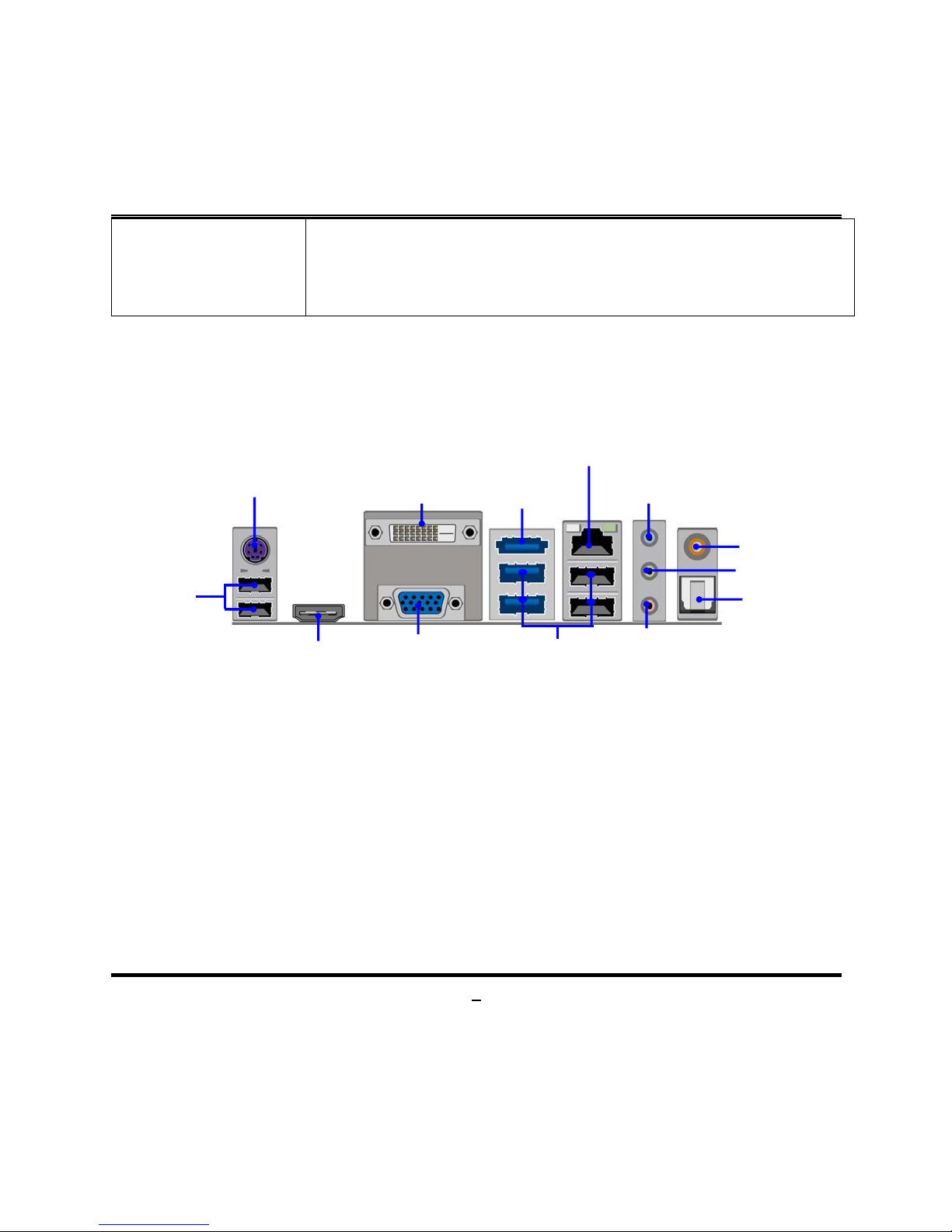
1-3 Layout Diagram
MIC-IN
VGA
Connector
Line-IN
Line-OUT
USB Ports
PS/2 Keyboard
HDMI
Connector
RJ-45 LAN Connector
DVI
Connector
E-SATA
Connector
USB Ports
Coaxial
SPDIF
_
OUT
Optical
SPDIF
_
OUT
Page 9
4
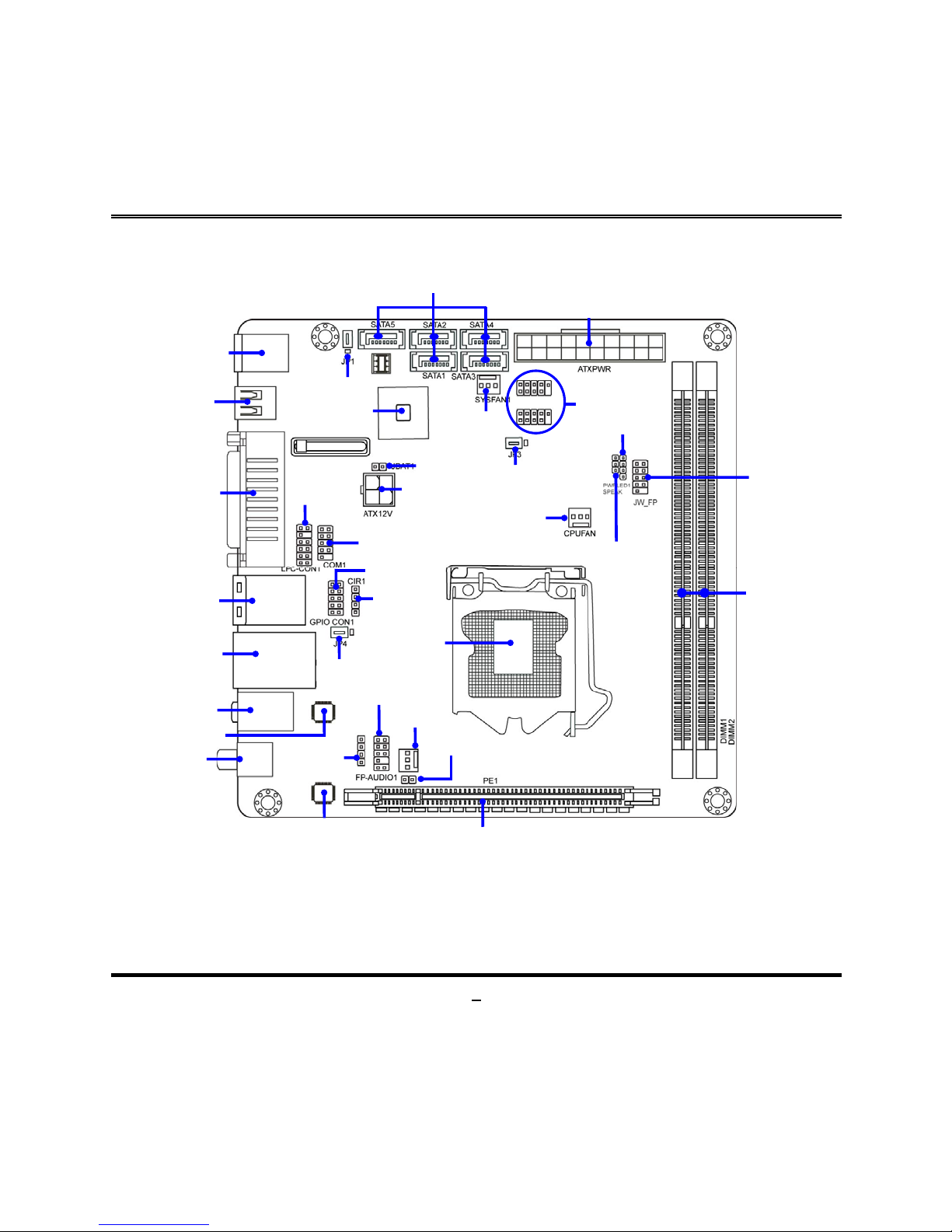
ALC 662 Audio Codec
USB Headers
Keyboard Port over
USB Ports
JBAT1
SYS FAN2
Header
SATAII Connecto
r
(1, 2, 3, 4,5)
ATX Powerconnector
ATX 12V Powe
r
Connector
DDRIII Memory Modules
(DDRIII 1066/1333)
Front Panel
Heade
r
Speaker1 Heade
r
CIR1 Heade
r
DVI Connector over
VGA Connecto
r
Coaxical
/
Optical
SPDIF_OUT Connectors
E-SATA over
USB Ports
Audio Connector
CDIN1 Header
CPU Socket
HDMI Connector
RJ-45 over
USB Ports
HDMI_SPDIF heade
r
JP4
JP1
JP3
Serial Port Heade
r
Front panel
Audio Heade
r
CPUFAN
Header
Intel H55/H57
Ex
p
ress
SYS FAN1
Header
PCI Express 2.0 x16
by 16 lane slot
PWRLED1 Header
Gigabit PCI-E
LAN Chi
p
GPIO1 Heade
r
LPC1
Header
Page 10

5
Jumper
Jumper Name Description
JBAT1 CMOS RAM Clear Function Setting 2-pin Block
JP1 KB/MS/ USB Power On Function Setting 3-pin Block
JP4 USB Power On Function Setting 3-pin Block
JP3 USB 1/2 Power On Function Setting 3-pin Block
Connectors
Connector Name Description
ATXPWR1 ATX Power Connector 24-pin Block
ATX12V1 ATX 12V Power Connector 4-pin Connector
KB(from UK1) PS2 Keyboard Connector 6-pin Female
HDMI1 High-Definition Multimedia Interface 19-pin Connector
VGA1 Video Graphic Attach Connector 15-pin Female
DVI1 Digital Visual Interface 24-pin Connector
USB (from
UK1,US1,UL1)
USB Port Connectors 4-pin Connectors
RJ-45 LAN
(from UL1)
RJ-45 LAN Connectors 8-pin Connector
ESATA(from US1) External Serial ATAII Connector 7-pin Connector
SATA1/SATA2
SATA3/SATA4/
SATA5
Serial ATAII Connectors 7-pin Connectors
AUDIO1 Line Out /Line In /MIC Audio Connector 3 -phone Jack
Page 11

6
Headers
Header Name Description
FP_AUDIO1 Front panel audio Headers 9-pin block
CDIN1 CD Audio-In Header 4-pin Block
HDMI-SPDIF1 SPDIF-Out header 2-pin Block
COM1 Serial Port Header 9-pin Block
USB1/USB4 USB Header 9- pin Block
GPIO_CON1 GPIO header 10-pin Block
SPEAK1 Speaker Header 4-pin Block
PWR LED1 Power LED 3-pin Block
JW_FP1
(PWR LED/ HD LED/
/Power Button /Reset)
Front Panel Header
(PWR LED/ HD LED/ /Power
Button /Reset)
9-pin Block
CPUFAN1,SYSFAN1/2 FAN Speed Headers 3-pin Block
GPIO_CON1 GPIO Header 10-pin Block
CIR1 CIR Header 4-pin Block
LPC_CON1 LPC Header 11-pin Block
Page 12
7
Chapter 2
Hardware Installation
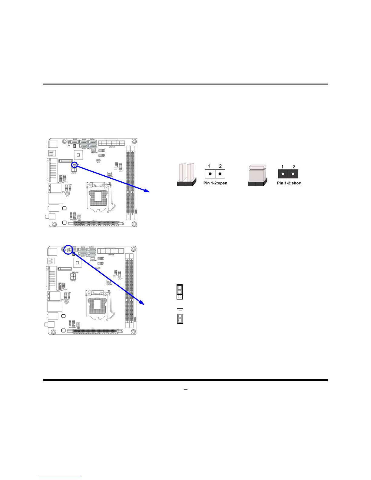
2-1 Jumper Setting
(1) Clear CMOS (2-pin): JBAT1
CMOS Clear Setting
1-2 Short: Clear CMOS
JBAT1
1-2 Open: Normal
(2) KB/MS/USB Power On Function Setting: JP1
2-3 cl osed: KB/MS/USB Power-on Enabled
JP1
JP1
1-2 C losed: K B/MS/USB Power-on Disabled(Default)
1
1
Page 13
8
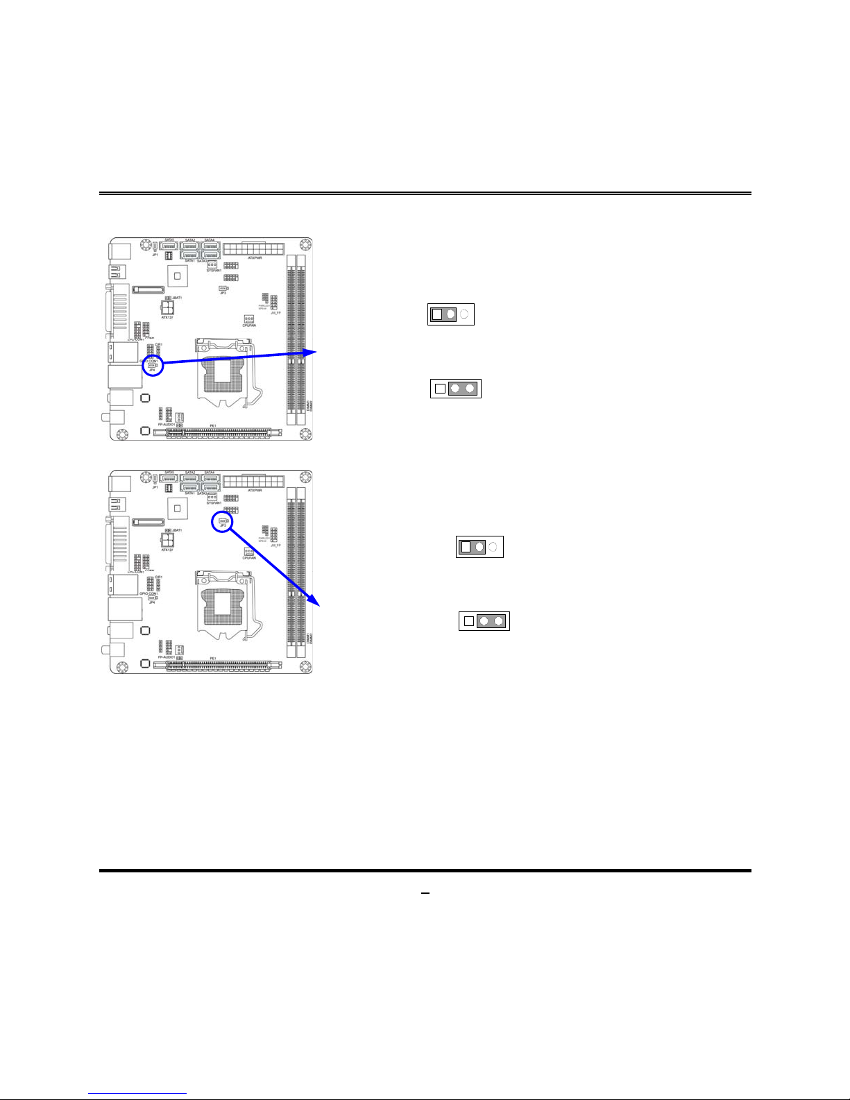
(3) USB Power On Function Setting: JP4
2-3 closed: USB Power-on Enabled
JP4
JP4
1-2 closed : USB Power-on Disacled(Default)
1
(4) USB 1/2 Power On Function Setting: JP3
2-3 closed: USB 1/4 Power-on Enabled
JP3
JP3
1-2 close d : USB 1/4 Power-on Di s acled(Default)
1
Page 14
9
2-2 Connectors and Headers
2-2-1 Connectors
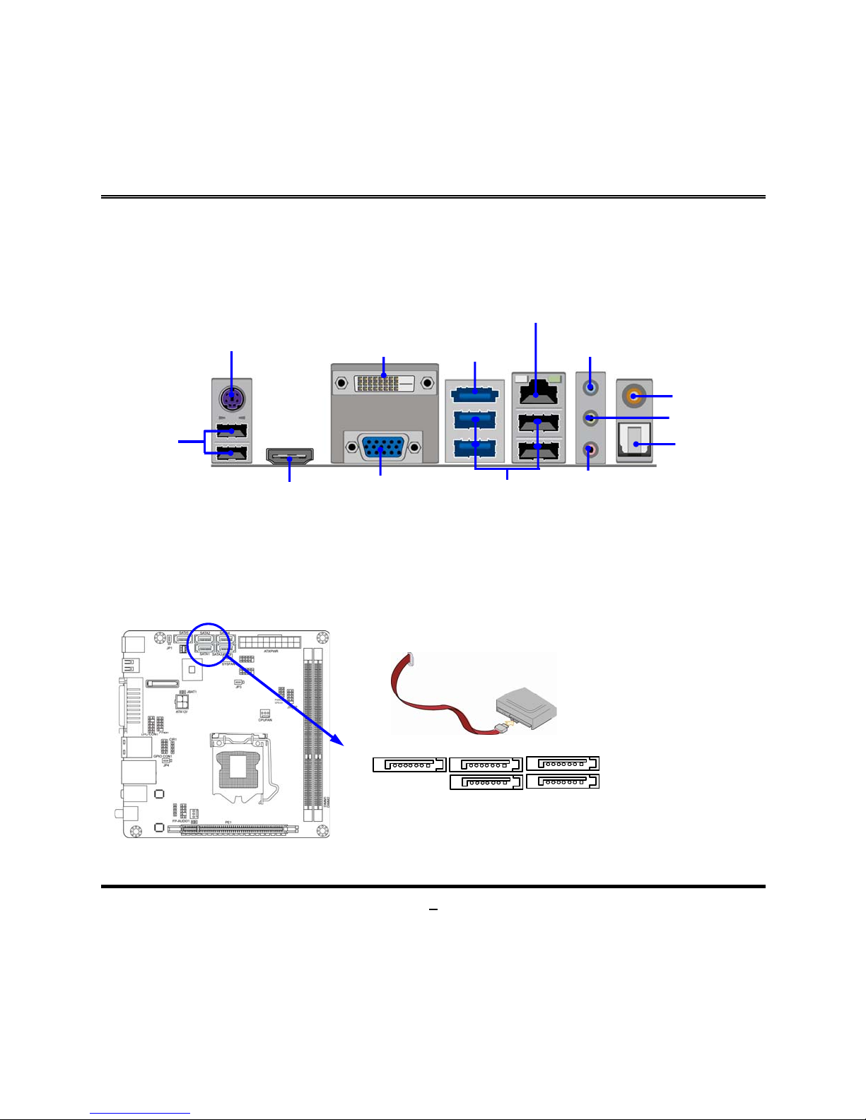
(1) Rear Panel Connectors
(2) Serial-ATAII Port connector: SATA1/SATA2/SATA3/SATA4/SATA5
These connectors support the provided Serial ATA and Serial ATA2 IDE hard disk
cable to connect the motherboard and serial ATA2 hard disk drives. All SATA ports
from model NC97R-LF also support RAID 0/1/5/10 function.
Serial-ATAII Connectors
SATA 1 SATA 2
SATA 3
SATA 4
SATA 5
MIC-IN
VGA
Connector
Line-OUT
Line-IN
USB Ports
PS/2 Keyboard
HDMI
Connector
RJ-45 LAN Connector
DVI
Connector
E-SATA
Connector
USB Ports
Coaxial
SPDIF OUT
Optical
SPDIF
_
OUT
Page 15
10
2-2-2 Headers
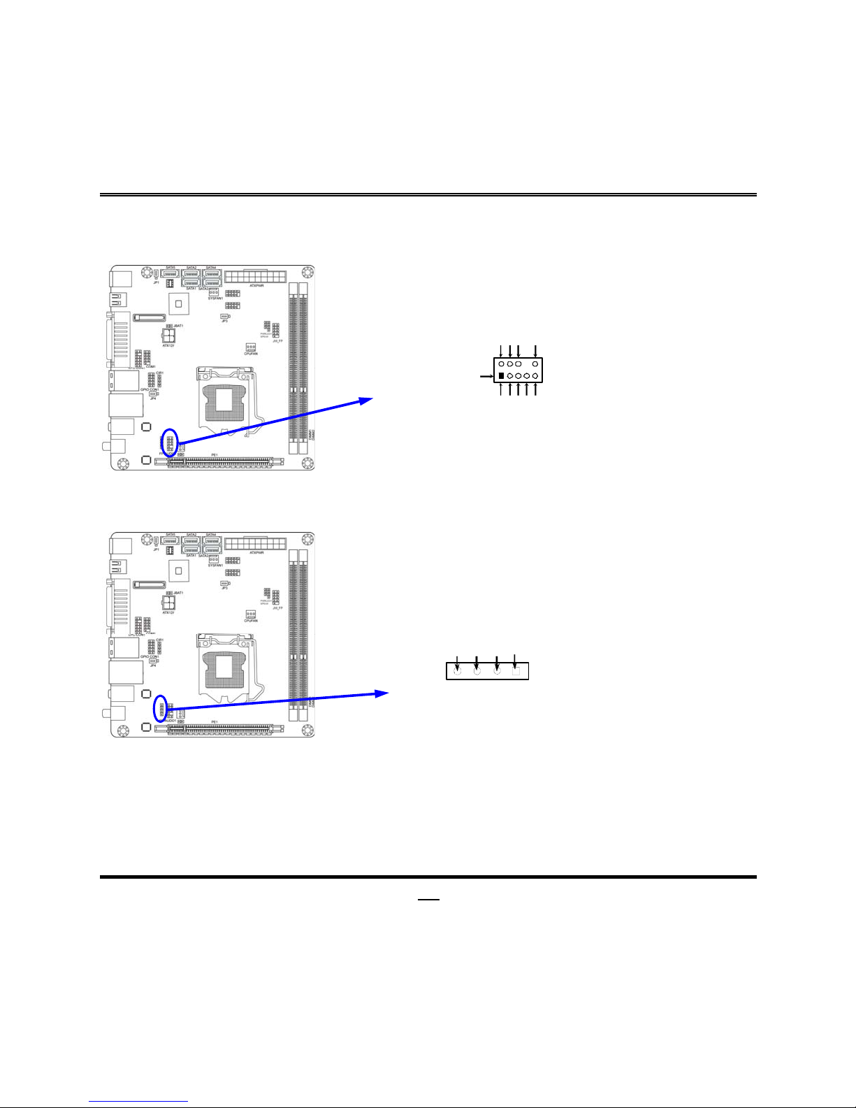
(1) Line-Out, MIC-In Header (9-pin): FP_AUDIO1
This header connects to Front Panel Line-out, MIC-In connector with cable.
Line-Out, MIC Headers
FP_AUDIO1
Pin 1
MIC2-
L
LINEOUT2-L
MIC2-R
LINEOUUT2-R
N
C
AUD
_
GND
NC
NC
AUD
_
JD
2
9
10
(2) CD AUDIO-In Headers (4-pin): CDIN1
CDIN are the connectors for CD-Audio Input signal. Please connect it to CD-ROM
CD-Audio output connector.
CD Audio-In Hea ders
CDIN1
4 1
GNDCD-R CD-LGND
(3) SPDIF Out header(2-pin): HDMI_SPDIF1
The SPDIF output is capable of providing digital audio to external speakers or
compressed AC3 data to an external Dolby digital decoder. Use this feature only
when your stereo system has digital input function.
Page 16
11
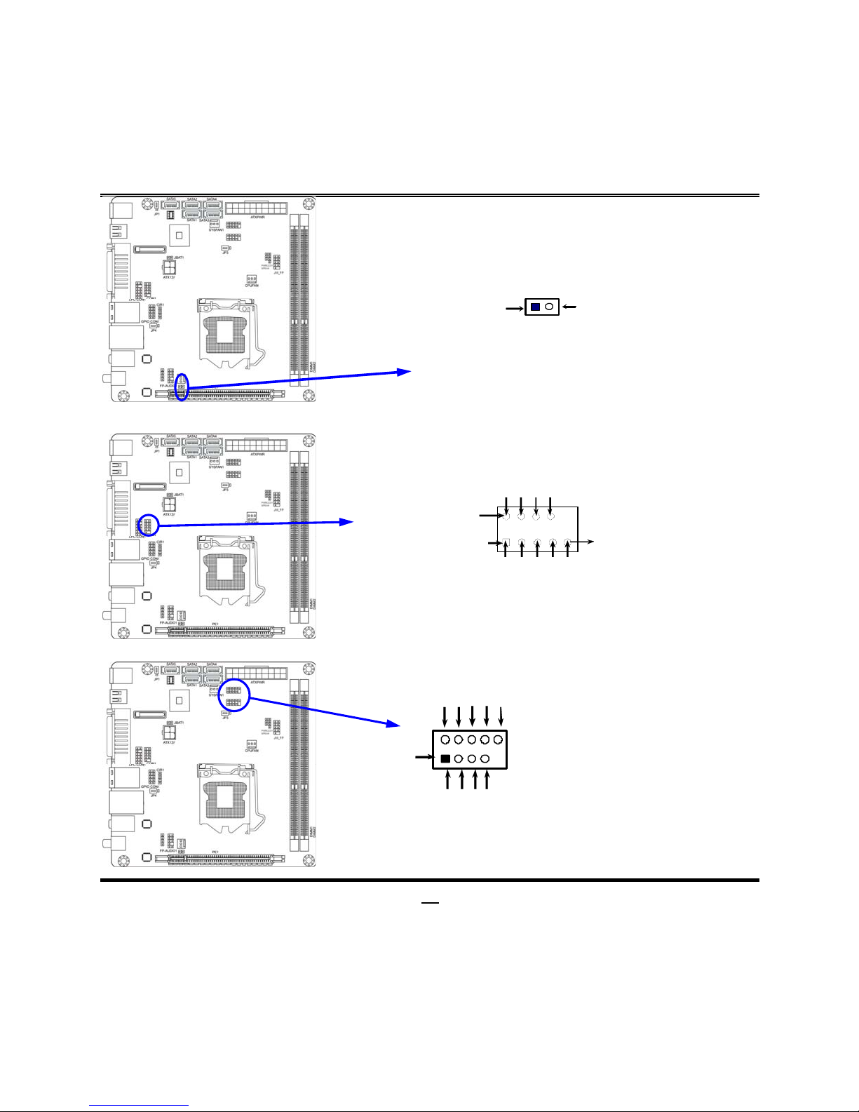
HDMI_SPDIF Header
GND
1 2
HDMI_SPDIF_OUT1
(4) Serial Port Connectors (9-Pin female): COM1
S erial COM Po rt 9-p i n Block
Pin1
Pin6
DCD
RXD
TXD
DTR
GND
DSR
RTS
CTS
RI
Pin1Pin1
Pin5
(5) USB Port Headers (9-pin): USB1/USB4
USB Port Header
VCC
Pin 1
-DATA
GND
+DATA
VCC
NC
-DATA
GND
+DATA
Page 17
12
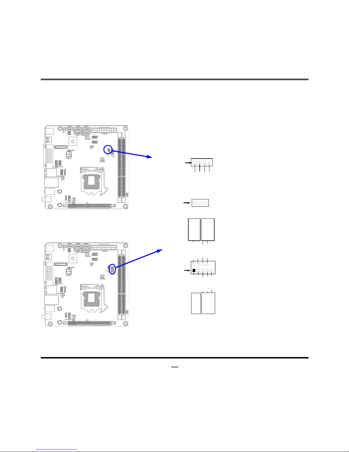
(6) Speaker Header: SPEAK1
This 4-pin header connects to the case-mounted speaker. See the figure below.
(7) Power LED: PWR LED1
The Power LED is light on while the system power is on. Connect the Power LED
from the system case to this pin.
SPEAK1
SPEAK
NC
NC
VCC
Pin 1
PWRLED1
Pin 1
(8) Front Panel Header: JW-FP1
System Case Connections
HDLED
RESET
HDDLED+
GND
PWRLED +
PWR LED
PWRBTN
PWRBTN
PWRLED-
HDDLED-
RSTSW
NC
GND
JW_FP
Pin 1
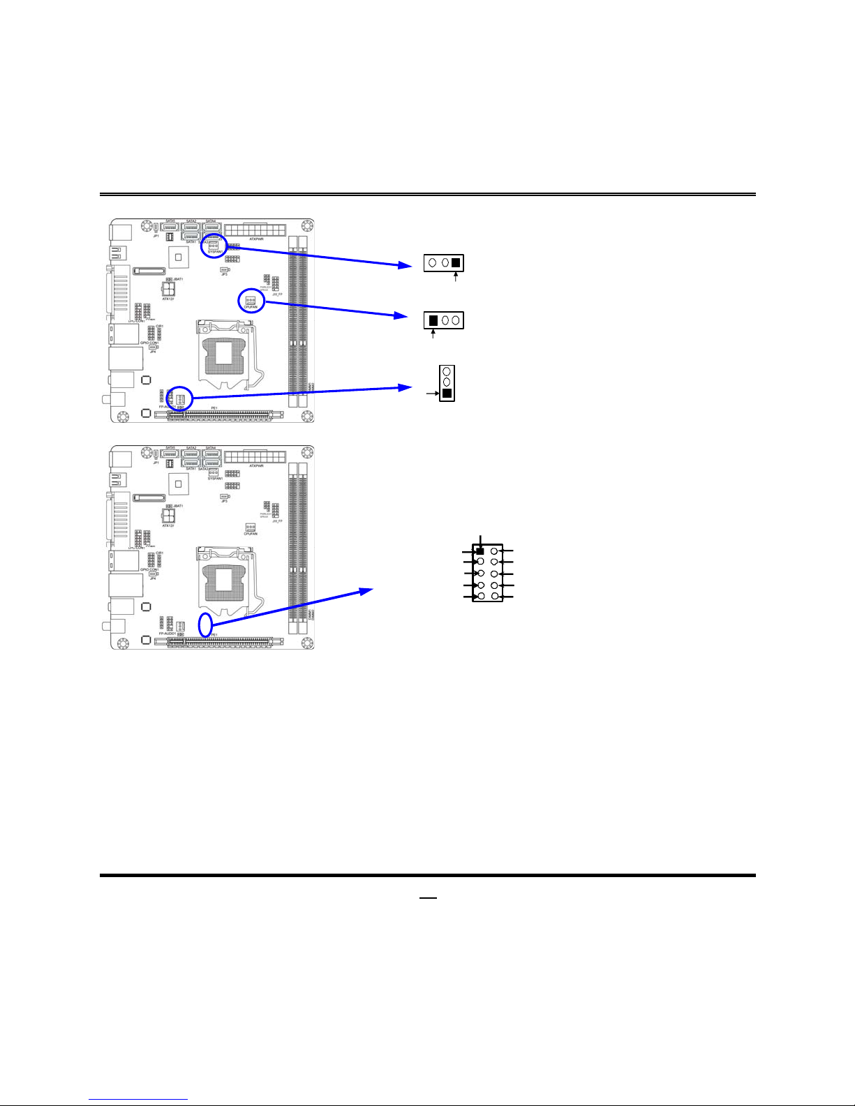
(9)FAN Speed Headers (3-pin): CPUFAN1, SYSFAN1/SYSFAN2
Pin1: GND
Pin2: +12V fan power
Page 18
13
Pin3: Fan Speed
3
1
1
3
SYS
FAN1
CPUFAN
SYSF AN2
1
3
(10) GPIO Header (10-pin): GPIO_CON1
GPIO_CON1 Header
GPIO_CON1
9
2
Pin 1
10
GPIO_10
GPIO_11
GPIO_12
GPIO_13
GND
GPIO_14
GPIO_15
GPIO_16
GPIO_17
VCC
Page 19
14
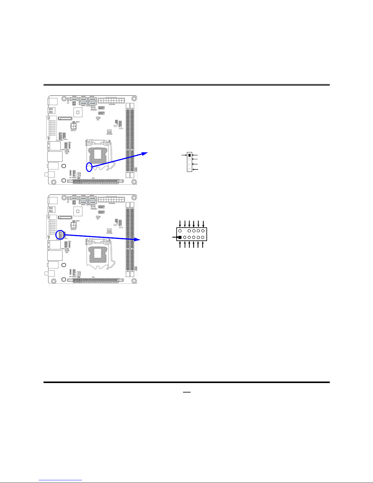
(11) CIR Header: CIR1
CIR1 Header
4
5VSB
CIR_RX
GND
CIR LED
Pin 1
(12) LPC Connector (12-pin): LPC_CON1
LPC1 Connector
11
LPC
_
CLK
VCC3
LFRAME
LPCRST
LAD3
GND
VCC
NC
2
Pin 1
12
LAD2
LAD1
GND
LAD0
Page 20

15
Chapter 3
Introducing BIOS
Notice! The BIOS options in this manual are for reference only. Different
configurations may lead to difference in BIOS screen and BIOS
screens in manuals are usually the first BIOS version when the board is
released and may be different from your purchased motherboard.
Users are welcome to download the latest BIOS version form our
official website.
The BIOS is a program located on a Flash Memory on the motherboard. This program
is a bridge between motherboard and operating system. When you start the computer,
the BIOS program will gain control. The BIOS first operates an auto-diagnostic test
called POST (power on self test) for all the necessary hardware, it detects the entire
hardware device and configures the parameters of the hardware synchronization.
Only when these tasks are completed done it gives up control of the computer to
operating system (OS). Since the BIOS is the only channel for hardware and software
to communicate, it is the key factor for system stability, and in ensuring that your
system performance as its best.
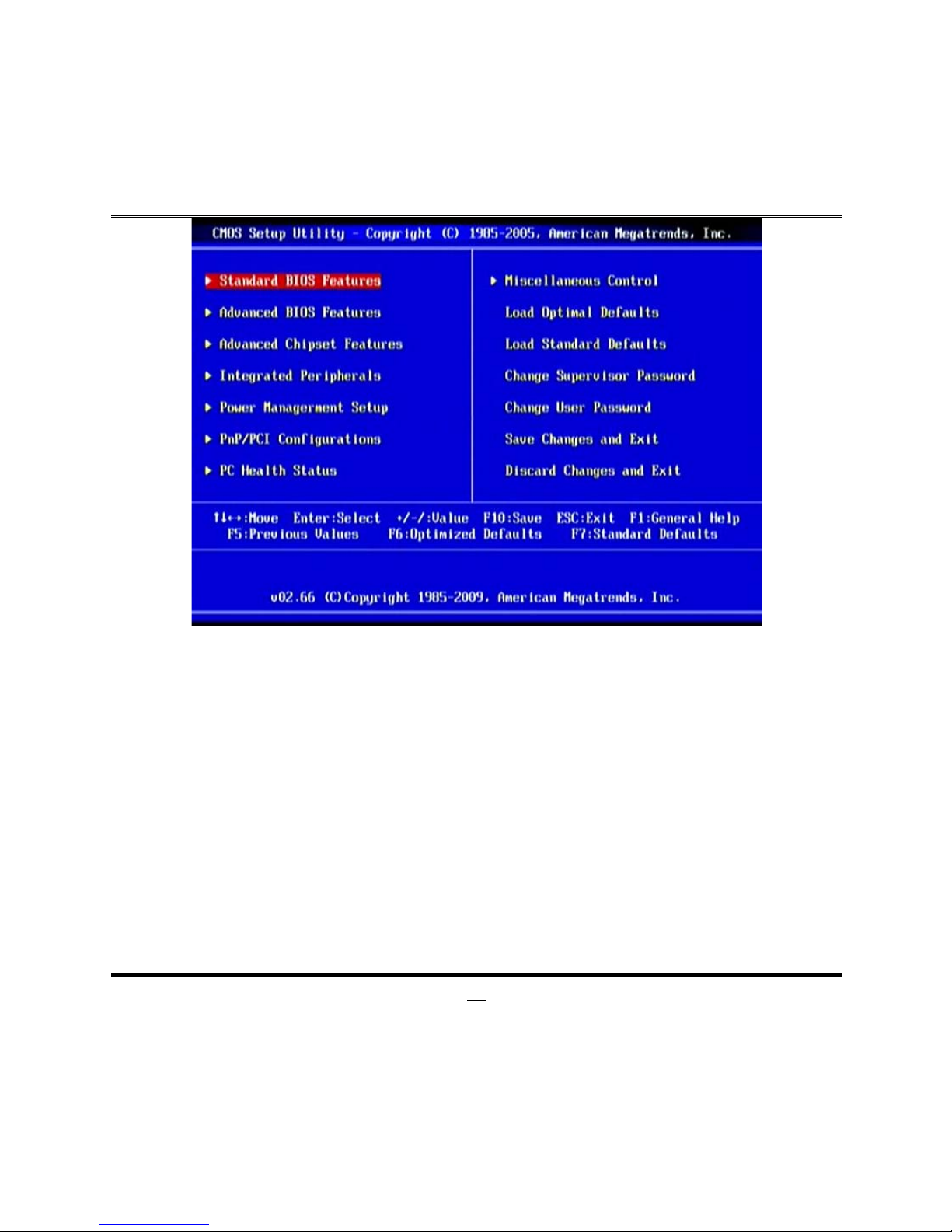
In the BIOS Setup main menu of Figure 3-1, you can see several options. We will
explain these options step by step in the following pages of this chapter, but let us first
see a short description of the function keys you may use here:
•
Press <Esc> to quit the BIOS Setup.
•
Press ↑↓←→ (up, down, left, right) to choose, in the main menu, the option you
want to confirm or to modify.
•
Press <F10> when you have completed the setup of BIOS parameters to save
these parameters and to exit the BIOS Setup menu.
•
Press Page Up/Page Down or +/– keys when you want to modify the BIOS
parameters for the active option.
Page 21

1
6
3-1 Entering Setup
Power on the computer and by pressing <Del> immediately allows you to enter Setup.
If the message disappears before your respond and you still wish to enter Setup,
restart the system to try again by turning it OFF then ON or pressing the “RESET”
button on the system case. You may also restart by simultaneously pressing <Ctrl>,
<Alt> and <Delete> keys. If you do not press the keys at the correct time and the
system does not boot, an error message will be displayed and you will again be asked
to
Press <Del> to enter Setup
3-2 Getting Help
Main Menu
The on-line description of the highlighted setup function is displayed at the bottom of
the screen.
Status Page Setup Menu/Option Page Setup Menu
Press F1 to pop up a small help window that describes the appropriate keys to use
and the possible selections for the highlighted item. To exit the Help Window, press
<Esc>.
3-3 The Main Menu
Once you enter AMI ® BIOS CMOS Setup Utility, the Main Menu (Figure 3-1) will
appear on the screen. The Main Menu allows you to select from twelve setup
functions and two exit choices. Use arrow keys to select among the items and press
<Enter> to accept or enter the sub-menu.
Page 22
1
7
Figure 3-1
Standard BIOS Features
Use this Menu for basic system configurations.
Advanced BIOS Features
Use this menu to set the Advanced Features available on your system.
Advanced Chipset Features
Use this menu to change the values in the chipset registers and optimize your
system’s performance.
Integrated Peripherals
Use this menu to specify your settings for integrated peripherals.
Power Management Setup
Use this menu to specify your settings for power management.
PnP/PCI Configurations
Use this menu to specify your settings for PnP and PCI configurations.
PC Health Status
Page 23

18
This entry shows your PC health status.
Miscellaneous Control
Use this menu to specify your settings for Miscellaneous Control.
Load Optimal Defaults
Use this menu to load the BIOS default values these are setting for optimal
performances system operations for performance use.
Load Standard Defaults
Use this menu to load the BIOS default values for the minimal/stable performance
system operation
Change Supervisor Password
This entry is for setting Supervisor password.
Change User Password
This entry for setting User password
Save Changes and Exit
Save CMOS value changes to CMOS and exit setup.
Discard Changes and Exit
Abandon all CMOS value changes and exit setup.
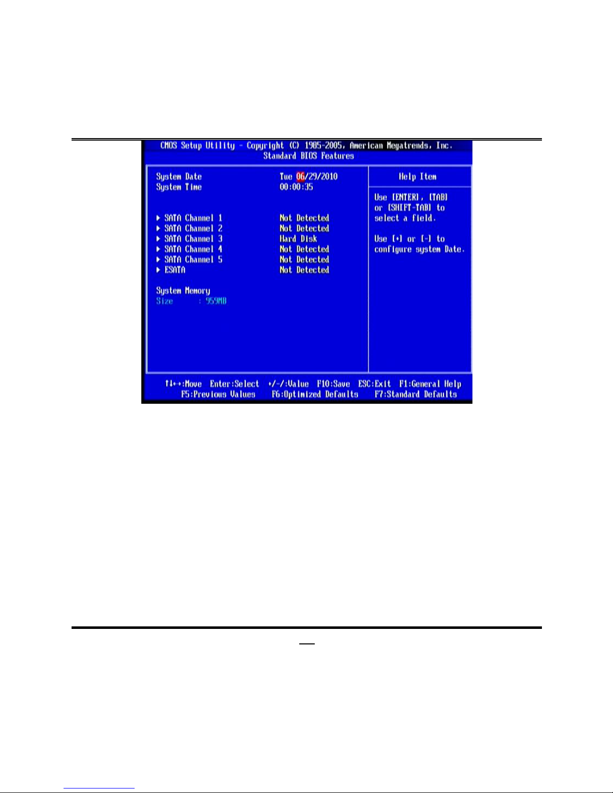
3-4 Standard BIOS Features
The items in Standard CMOS Setup Menu are divided into several categories. Each
category includes no, one or more than one setup items. Use the arrow keys to
highlight the item and then use the <PgUp> or <PgDn> keys to select the value you
want in each item.
Page 24
19
Date
The date format is <day><month><date><year>.
Day
Day of the week is from Sun to Sat, determined by BIOS. Read-only.
Month
The month is from Jan. through Dec.
Date
The date from 1 to 31 can be keyed by numeric function keys.
Year
The year depends on the year of the BIOS.
Time
The time format is <hour><minute><second>.
SATA Channel 1/2 /3/4/5; ESATA
While entering setup, BIOS auto detects the presence of IDE devices. This displays
the status of auto detection of IDE devices.
Type:
The optional settings are: Not Installed; Auto; CD/DVD and ARMD. Use the
item to select the type of device connected to the system.
LBA/Large Mode:
The optional settings are Auto; Disabled.
Disabled: disables LBA mode.
Page 25

20
Auto: enables LBA Mode if the devices support it and the device is not already
formatted with LBA Mode disabled.
Block (Multi-Sector Transfer):
The optional settings are: Disabled and Auto.
Disabled: The Data transfer from and to the device occurs one sector at a time.
Auto: The Data transfer from and to the device occurs multiple sectors at a time if the
device supports it.
PIO Mode:
the optional settings are: Auto, 0, 1, 2, 3 and 4. Use the item to select PIO
mode
DMA MODE:
the optional settings are Auto, SWDMAn, MWDMAn , UDMAn.
S.M.A.R.T.:
This option allows you to enable the HDD S.M.A.R.T Capability
(Self-Monitoring, Analysis and Reporting Technology). The optional settings are Auto;
Disabled; and Eabled.
32 Bit Data Transfer:
the optional settings are: Disabled; Enabled.
Enable/disable 32-bit data transfer.
System Memory
This item will show information about the memory modules(s) installed.
Page 26
21
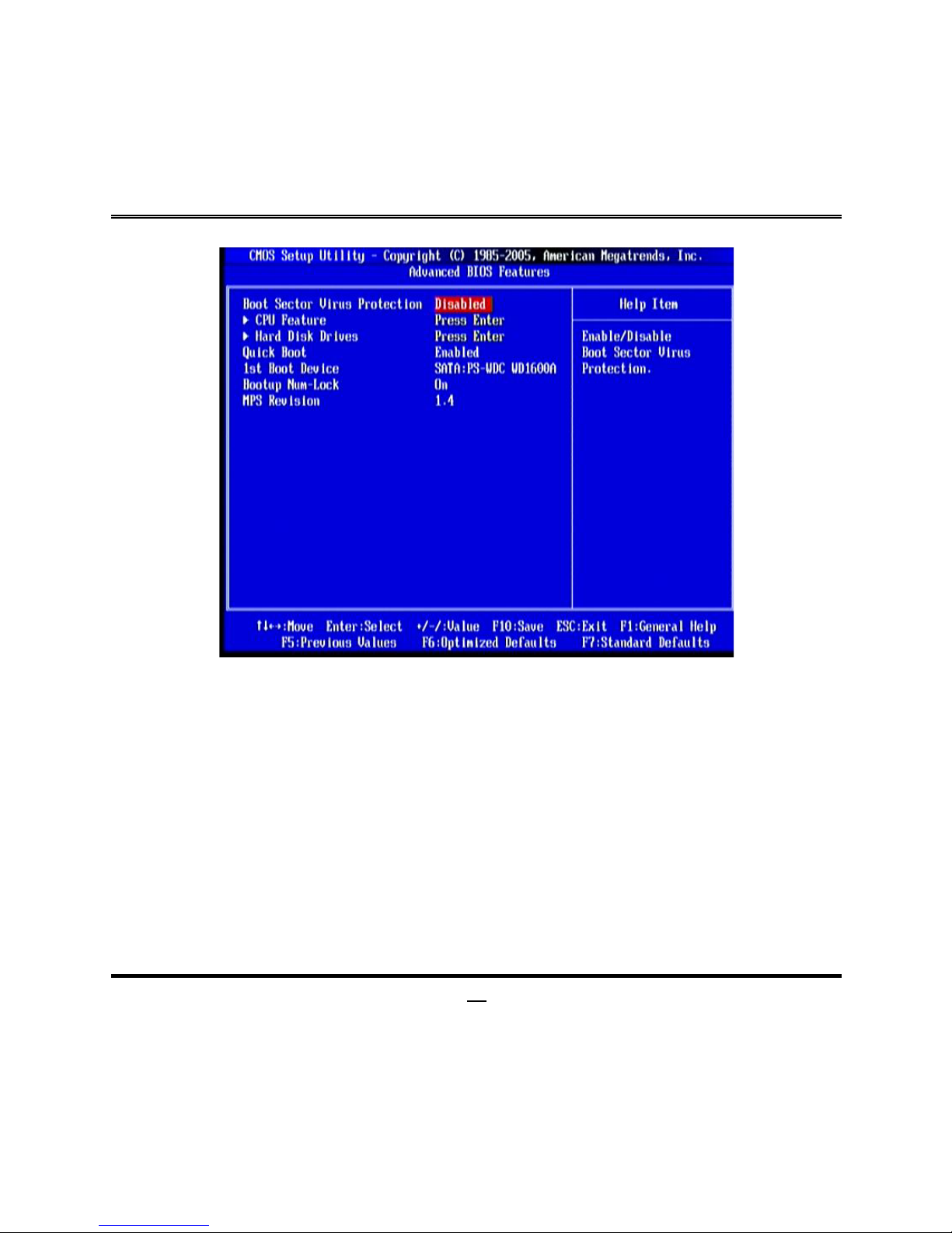
3-5 Advanced BIOS Features
Boot Sector Virus Protection
The selection Allow you to choose the VIRUS Warning feature for IDE Hard Disk boot
sector protection. If this function is enabled and someone attempt to write data into
this area, BIOS will show a warning message on screen and alarm beep.
Disabled
(default) No warning message to appear when anything attempts to
access the boot sector or hard disk partition table.
Enabled
Activates automatically when the system boots up causing a
warning message to appear when anything attempts to access
the boot sector of hard disk partition table.
Hard Disk Drives
Use the item to specify the boot device priority sequence from available hard driver.
Quick Boot
Allows BIOS to skip certain tests while booting. This will decrease the needed to boot
the system.
Page 27
22
1
st
Boot Devices
Specify the boot sequence from the available devices. A device enclosed in
parenthesis has been disabled in corresponding type menu.
Boot Up NumLock Status
The default value is On.
On
(default)
Keypad is numeric keys.
Off
Keypad is arrow keys.
MPS Version
This option is only valid for multiprocessor motherboards as it specifies the version of
The Multiprocessor Specification (MPS) that the motherboard will use.
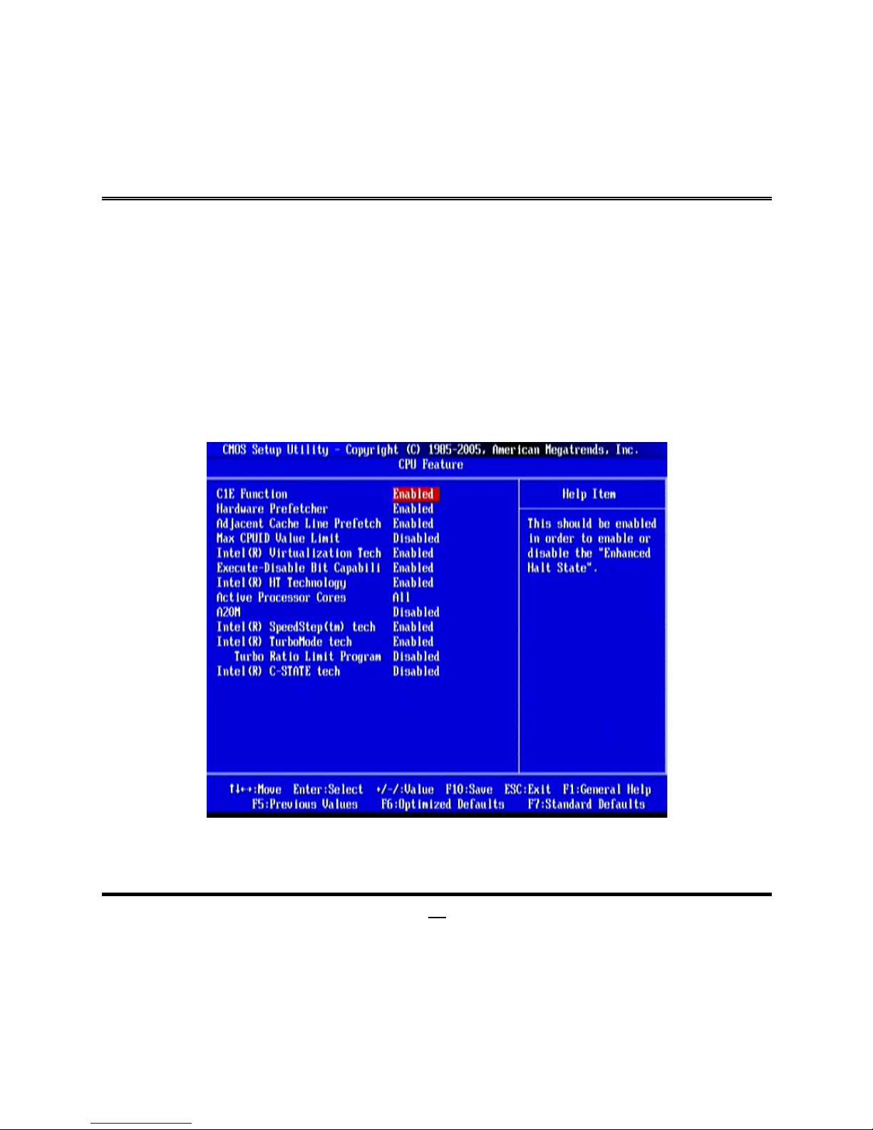
3-5-1 CPU Feature
C1E Function
This should be enabled in order to enable or disable the “Enhanced Halt State”. The
optional settings are: Enabled; Disabled.
Page 28

23
Hardware Prefetcher
For UP platform, leave it as Enabled. For DP/MP servers, it may use to tune
performance to the specific application. The optional settings are: Enabled; Disabled.
Adjacent Cache Line Prefetch
For UP platform, leave it as Enabled. For DP/MP servers, it may use to tune
performance to the specific application. The optional settings are: Enabled; Disabled.
Max CPUID Value Limit
Set it as Disabled for Windows XP. The optional settings are: Enabled; Disabled.
Intel (R) Virtualization Tech
When this item is set as Enabled, a VMM can utilize the additional HW Caps.
Provided by Intel(R) Virtulization Tech. Note: A full reset is required to change the
setting. The optional settings are: Enabled; Disabled.
Execute-Disable Bit Capabili
When disabled, force the XD feature flag to always return 0. The optional settings are:
Enabled; Disabled.
Intel(R) HT Technology
When Disabled, only one thread per enabled core is enabled. The optional settings
are: Enabled; Disabled.
Active Processor Core
Use this item to decide the number of cores to enable in each processor package. The
optional settings are: All; 1, 2, 3 and 4.
A20M
Legacy OSes and APs may need A20M enabled. The optional settings are: Enabled;
Disabled.
Intel(R) SpeedStep (tm)tech
The optional settings are: Enabled; Disabled.
Disable: Disable GV3.
Enabe: Enable GV3.
InteL(R) TurboMode tech
Turbo mode allows processor cores to run faster than marked frequency in specific
condition.
Turbo Ratio Limit Program
Page 29
24
Use this item to enable or disable turbo ratio mode programming.
Intel(R) C-STATE tech
CState: CPU idle is set to C2/C3/C4.
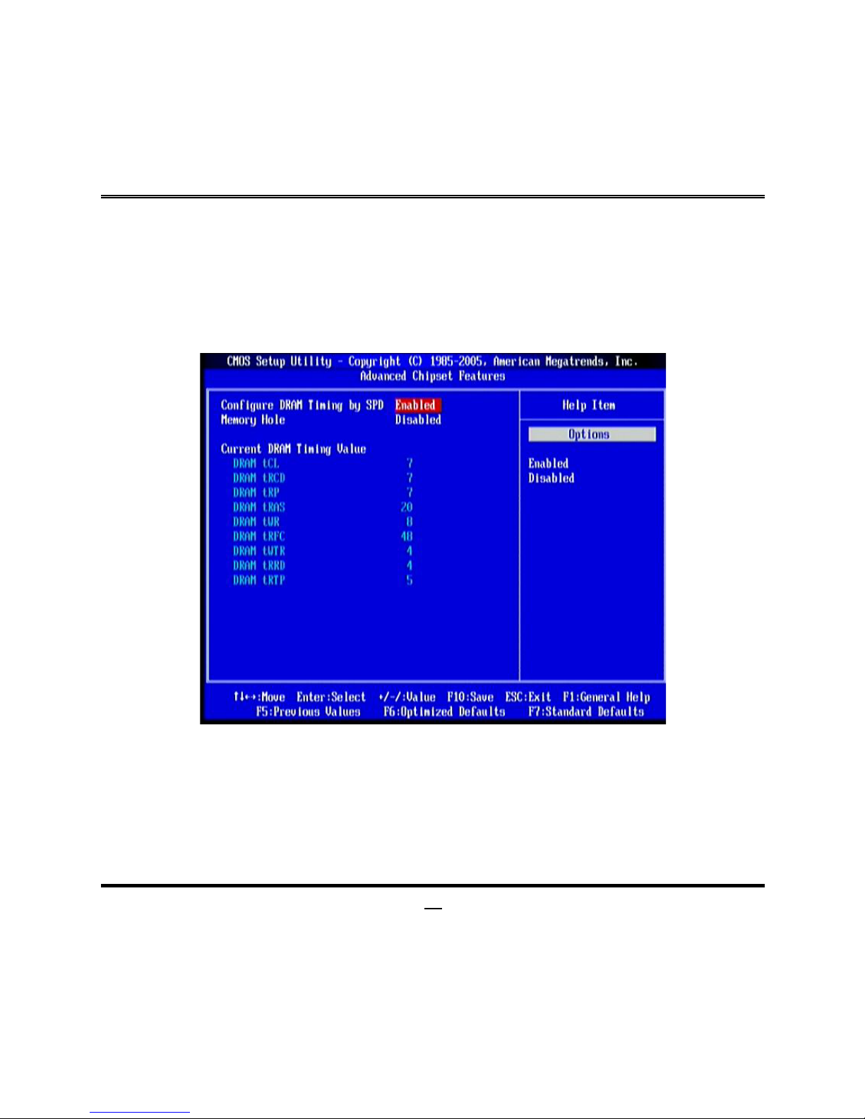
3-6 Advanced Chipset Features
The Advanced Chipset Features Setup option is used to change the values of the
chipset registers. These registers control most of the system options in the computer.
Configure DRAM Timing by SPD
The optional setting is: Disabled; Enabled.
Memory Hole
The optional settings are: Disabled; 15MB-16MB.
Page 30
25
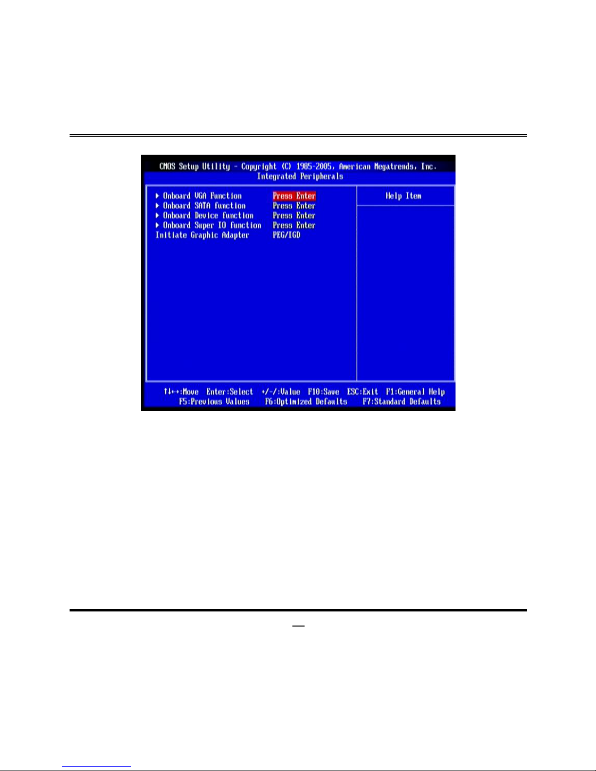
3-7 Integrated Peripherals
Initiate Graphics Adapter
Select which graphics controller to use as the primary boot device. The optional
settings are: IGD; PEG/IGD.
Page 31
26
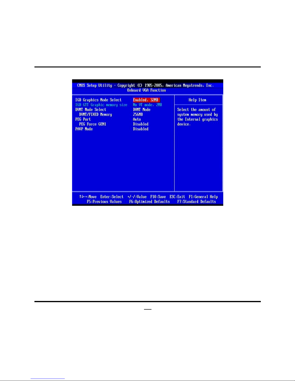
3-7-1 Onboard VGA Function
IGD Graphics Mode Select
Use this item to select the amount of system memory used by the internal graphics
device. The optional setting: Enable, 32MB; Enable, 64MB; Enable, 128MB.
DVMT/FIXED Memory
The optional settings are: 128MB; 256MMB; Maximum DVMT.
PEG Port
The optional settings are: Auto; Disabled.
PEG Force GEN1
The optional settings are: Enabled; Disabled.
Page 32
27
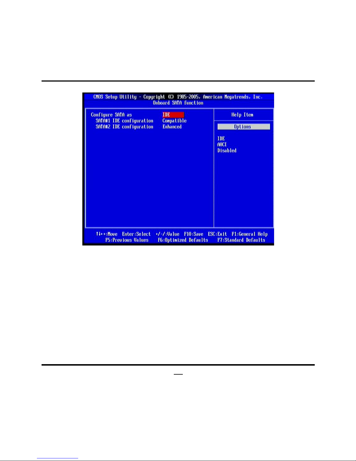
3-7-2 Onboard SATA Function
Configure SATA as
Press Enter to select the SATA type. The optional settings are: IDE; AHCI and
Disabled.
SATA#1 IDE Configuration
The optional settings are: Compatible and Enhanced.
SATA#2 IDE Configuration
The optional settings are: Disabled and Enhanced.
Page 33
28
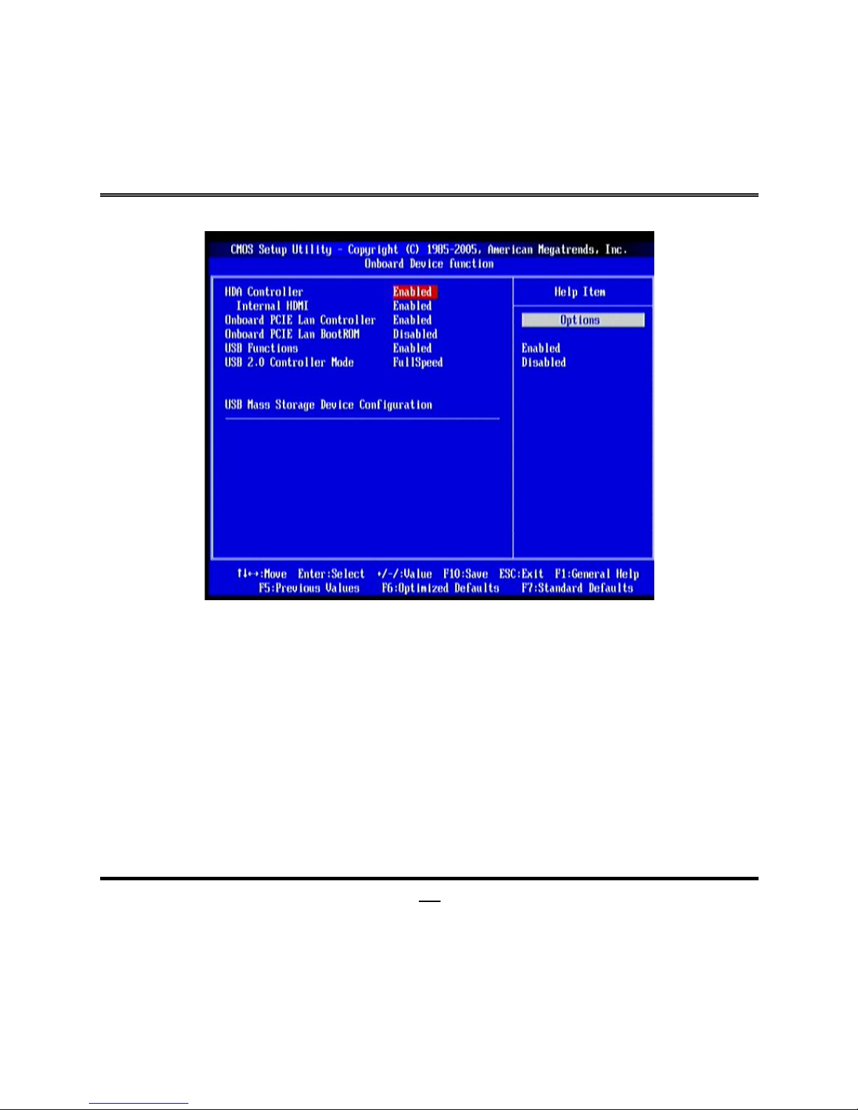
3-7-3 Onboard Device Function
HDA Controller
The optional setting are: Enabled; Disabled.
Onboard PCIE Lan Controller
Use this item to enable or disable onboard PCIE Lan controller.
Onboard PCIE Lan BootROM
The optional settings are: Disabled; Enabled.
USB Functions
The optional settings are: Disabled; Enabled.
USB 2.0 Operation Mode
The settings are: FullSpeed; HiSpeed. Use the item to configure the USB 2.0
controller in HiSpeed (480Mbps) or FullSpeed (12Mbps).
Page 34
29
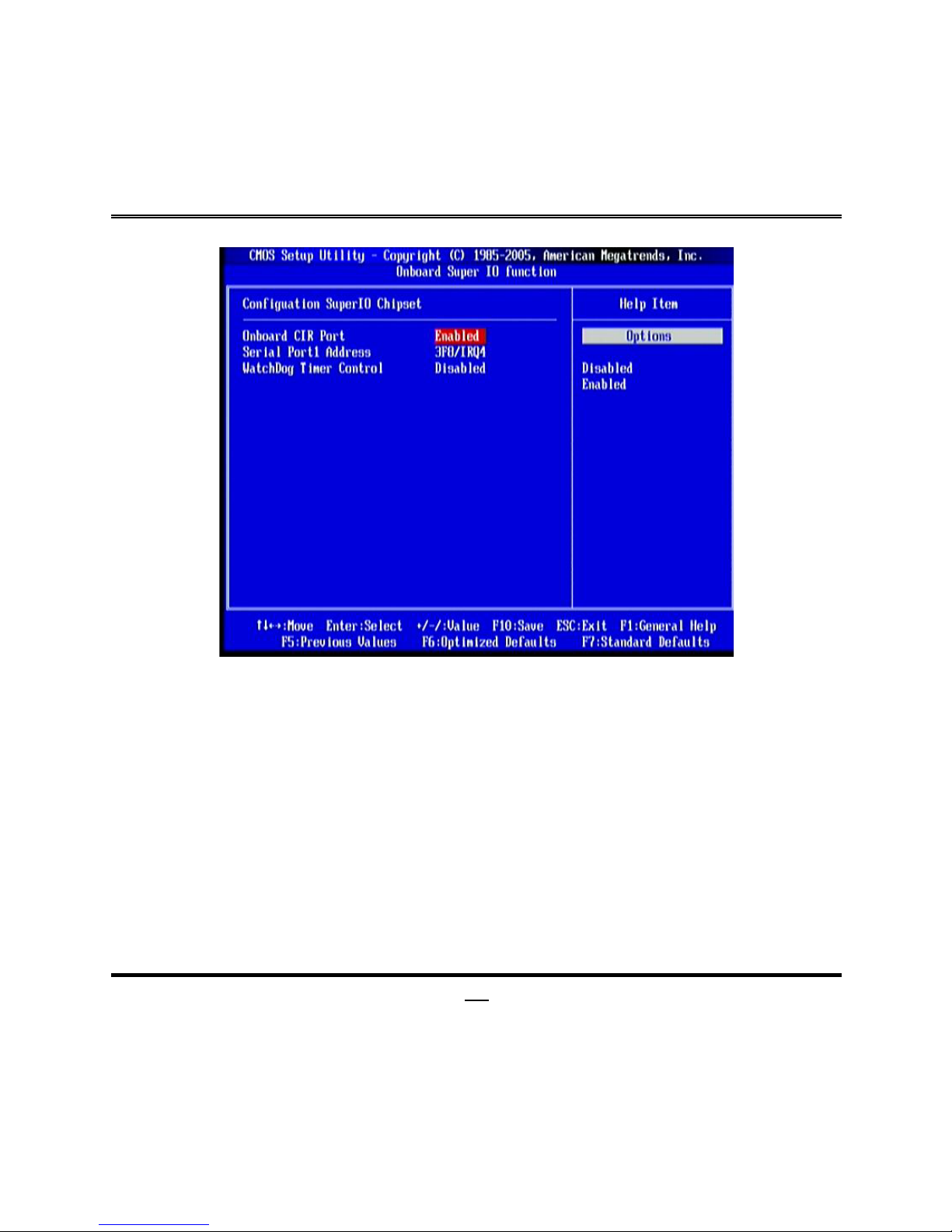
3-7-4 Onboard Super IO Function
Onboard CIR Port
Use this item to enable or disable CIR port.
Serial Port 1 Address
The optional settings are:Disabled, 3F8/IRQ4, , 2F8/IRQ3,3E8/IRQ4, 2E8/IRQ3.
This item allows BIOS to select Serial Port1 Base Addresses.
WatchDog Timer Control
Use this item to enable or disable WatchDog Timer Control. When set as Enabled, the
following sub-items shall appear:
WatchDog Timer Value
User can set a value in the range of 10 to 255.
WatchDog Timer Unit
The optional settings are: Sec.; Min..
Page 35
30
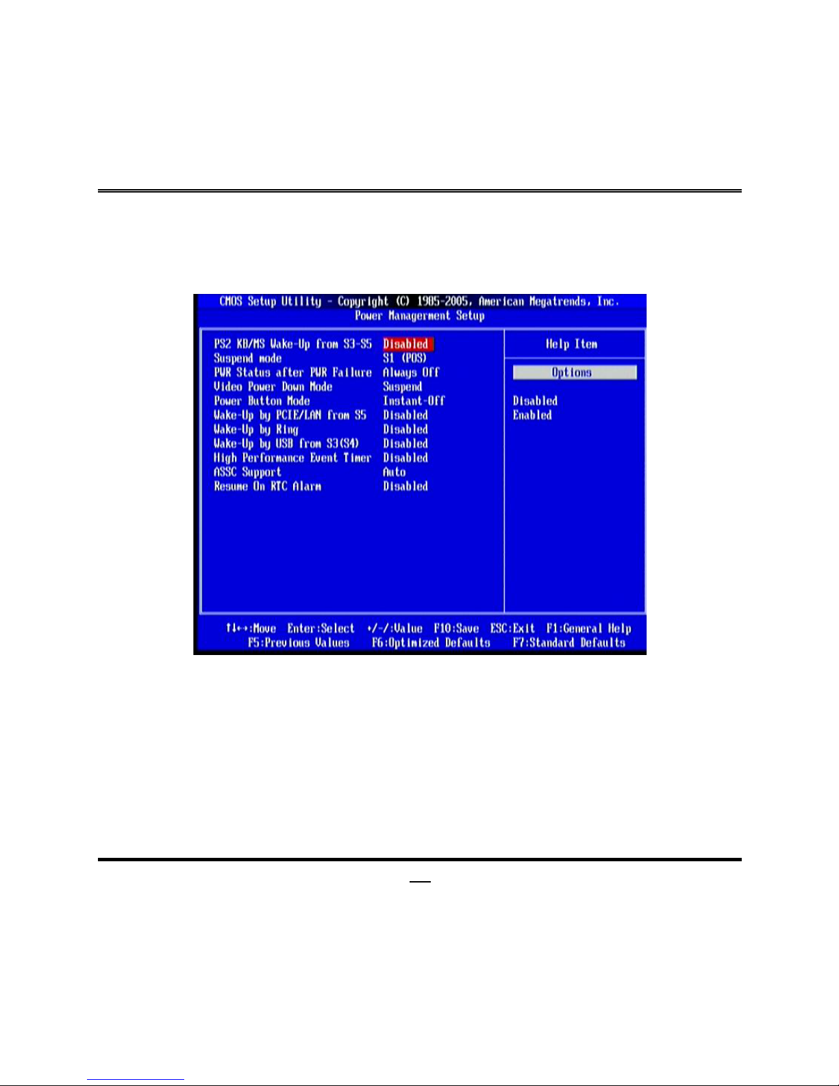
3-8 Power Management Setup
The Power Management Setup allows you to configure your system to most
effectively save energy saving while operating in a manner consistent with your own
style of computer use.
Suspend Mode
Select the ACPI states used for system suspend. The optional settings are: S1 (POS);
S3 (STR).
PWR Status after PWR Failure
The optional settings are: Always Off; Always On; Former Status.
Video Power Down Mode
The optional settings are: Disabled; Standby; Suspend.
Power Button Mode
The optional settings are: Instant-Off; Delay 4 Sec.
Wake-Up by PCI E/LAN from S5/ Wake-Up by Ring/Wake-Up by USB from S3(S4)
Page 36
31
To generate a wake event by the above devices. The optional settings are: Enabled;
Disabled.
High Performance Event Timer
The optional settings are: Enabled; Disabled.
ASSC Support
The optional settings are: Disabled; Auto.
Resume On RTC Alarm
Use this item to disable or enable RTC to generate a wake event.
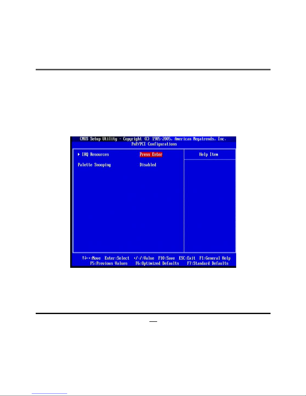
3-9 PnP/PCI Configurations
IRQ Resources
Names the interrupt request (IRQ) line assigned to the USB on your system. Activity
of the selected IRQ always awakens the system.
Palette Snoop
The options are Disabled or Enabled. Enabled: informs the PCI devices that an ISA
graphics device is installed in the system so the card will function correctly.
Page 37
32
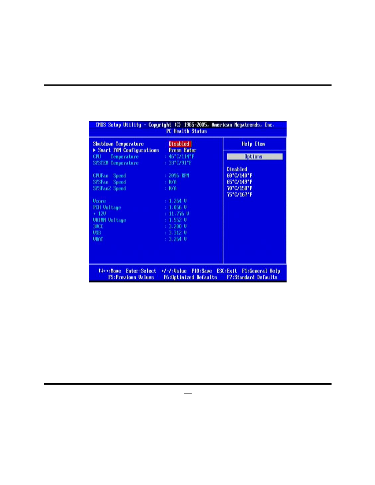
3-10 PC Health Status
This section shows the Status of your CPU, Fan, and Warning for overall system
status. This is only available if there is Hardware Monitor onboard.
Smart Fan Configuration
Press Enter to set certain values for the following three items: CPUFAN Smart Mode;
SYSFAN1 Smart Mode; SYSFAN2 Smart Mode.
CPU Temperature/System Temperature/CPUFAN Speed/SYSFAN
Speed/SYSFAN2 Speed/Vcore/PCH Voltage/+12V/VDIMM
Voltage/3VCC/VSB/VBat
This will show the CPU/FAN/System voltage chart and FAN Speed, etc.
Page 38
33
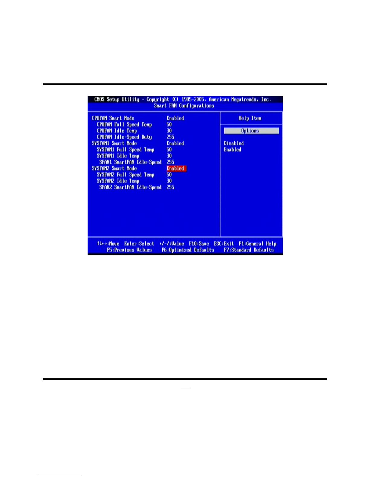
3-10-1 Smart FAN Configurations
CPU/ SYSFAN1/SYSFAN2 Full-Speed Temp
The optional range is 20~70. Fan will run in full speed mode when above the
temperature set in these items.
CPU/ SFAN1/SYSFAN2 Idle Temp
The optional range is 20~50. Fan will low speed when below this temperature.
CPU/ SFAN1/SYSFAN2 Idle-Speed
Fan duty control. The optional range is 0~255.
Page 39
34
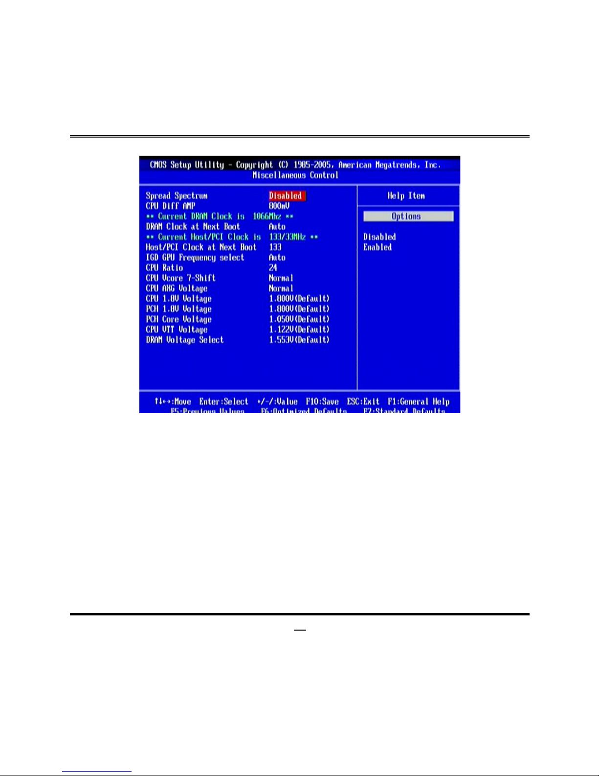
3-11 Miscellaneous Control
Spread Spectrum
The optional settings are: Enabled; Disabled.
CPU Diff AMP
The optional settings are: 700 mV; 800 mV;900 mV;1000 mV.
DRAM Clock at Next Boot
This item allows you to set DRAM clock. The optional settings are: Auto; 800MHz;
1066MHz; 1333MHz.
Host Clock at Next Boot
Use the item to set CPU frequency.
IGD GPU Frequency Select
Use this item to add GPU frequency by 7 steps. Please take note that adding
frequency too high may cause system instability.
Page 40

35
CPU Ratio
Use this item to set CPU ratio. This setting will only take effect when SpeedStep-tech
is set as Disabled.
CPU Vcore-7 Shift
Use this item to set value in CPU Vcore 7-Shift function. Optional settings are:
Normal; +50mV to 350mV.
CPU AGX Voltage Select
The optional settings are: Normal; +50mV~+350 mV.
DRAM Voltage Select
Use this item to set DRAM voltage.
3-12 Password Setting
You can set either supervisor or user password, or both of them. The differences are:
Supervisor password: Can enter and change the options of the setup menus.
User password: Can only enter but do not have the right to change the options
of the setup menus. When you select this function, the
following message will appear at the center of the screen to
assist you in creating a password.
ENTER PASSWORD:
Type the password, up to eight characters in length, and press <Enter>. The
password typed now will clear any previously entered password from CMOS memory.
You will be asked to confirm the password. Type the password again and press
<Enter>. You may also press <Esc> to abort the selection and not enter a password.
To disable a password, just press <Enter> when you are prompted to enter the
password. A message will confirm that the password will be disabled. Once the
password is disabled, the system will boot and you can enter Setup freely.
PASSWORD DISABLED.
When a password has been enabled, you will be prompted to enter it every time you
try to enter Setup. This prevents an unauthorized person from changing any part of
your system configuration.
Page 41
36
Additionally, when a password is enabled, you can also require the BIOS to request a
password every time your system is rebooted. This would prevent unauthorized use
of your computer.
You determine when the password is required within the BIOS Features Setup Menu
and its Security option. If the Security option is set to “System”, the password will be
required both at boot and at entry to Setup. If set to “Setup”, prompting only occurs
when trying to enter Setup.
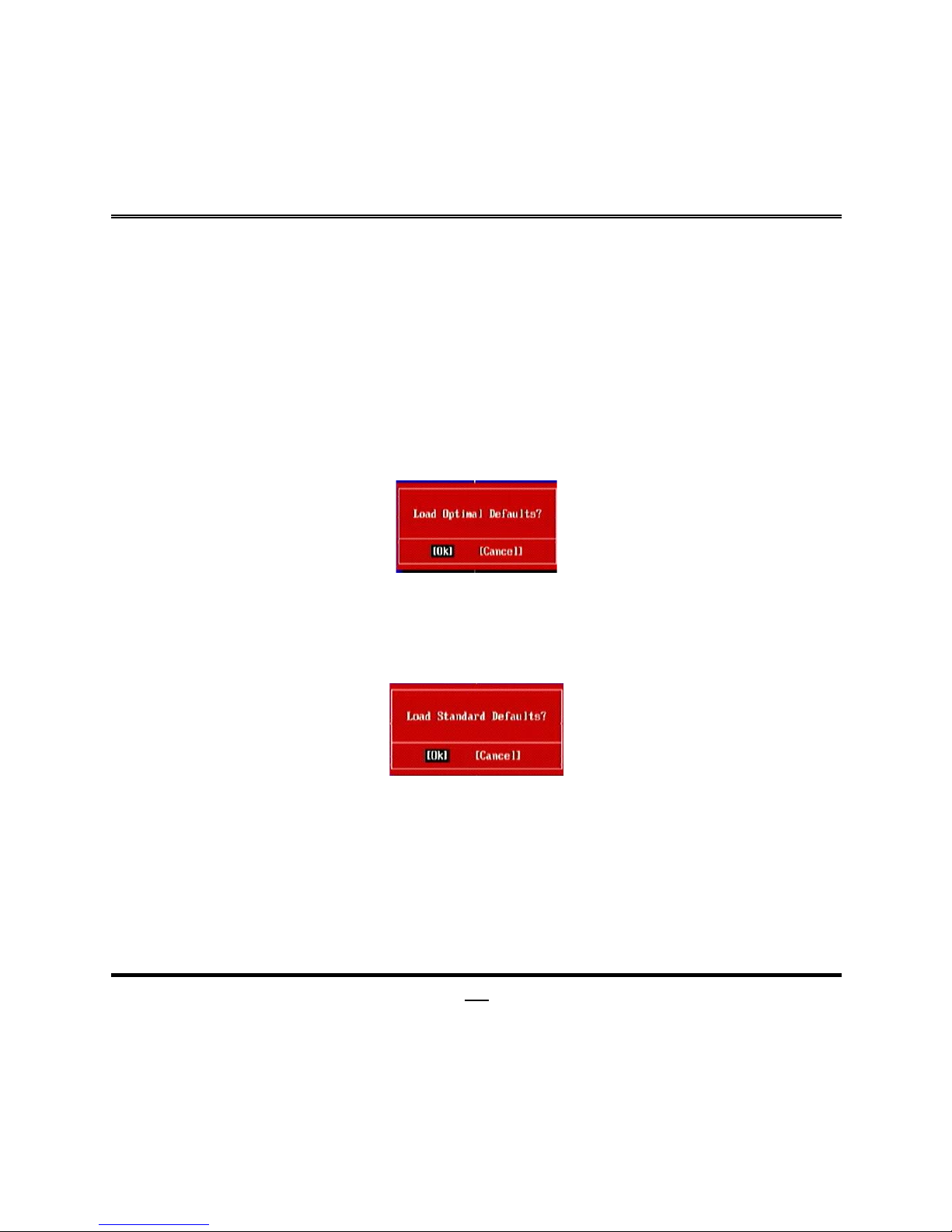
3-13 Load Optimal Defaults/ Load Standard Defaults
Load Optimal Defaults
When you press <Enter> on this item, you get a confirmation dialog box with a
message similar to:
Pressing <OK> loads the default values that are factory settings for optimal
performance system operations.
Load Standard Defaults
When you press <Enter> on this item, you get a confirmation dialog box with a
message similar to:
Pressing <OK> loads the default values that are factory settings for stable
performance system operations.
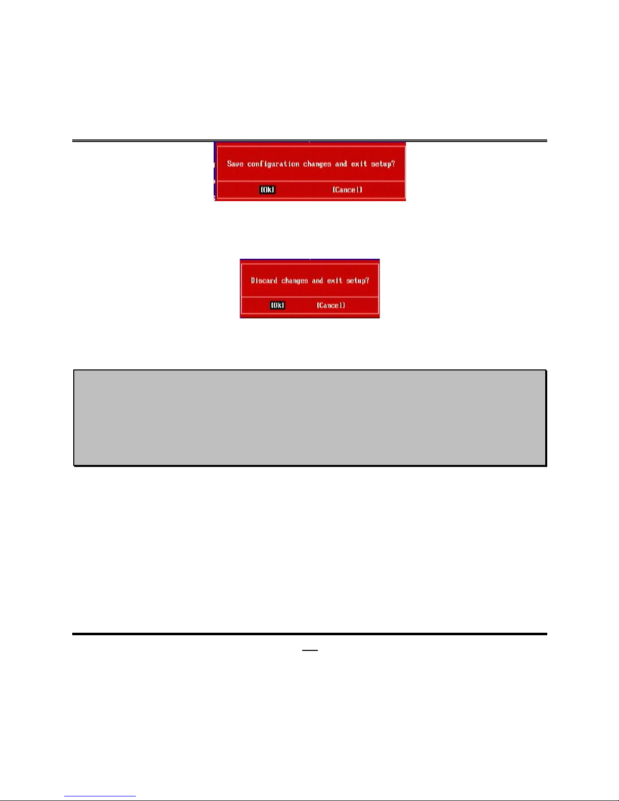
3-14 Save Changes and Exit / Discard Changes and Exit
Save Changes and Exit
When you press <Enter> on this item, you get a confirmation dialog box with a
message similar to:
Page 42
37
Pressing <OK> save the values you made previously and exit BIOS setup.
Discard and Exit
When you press <Enter> on this item, you get a confirmation dialog box with a
message similar to:
Pressing <OK> to leave BIOS setting without saving previously set values.
Notice!
The BIOS options in this manual are for reference only. Different
configurations may lead to difference in BIOS screen and BIOS
screens in manuals are usually the first BIOS version when the board is
released and may be different from your purchased motherboard.
Users are welcome to download the latest BIOS version form our
official website.
 Loading...