

Page 1

TECHNICAL MANUAL
Of
AMD 785G & SB 750
Based
Mini-ITX M/B for Socket AM2+/AM2
AMD Quad Core Processor
NO.G03-NC84-F
Revision: 3.0
Release date: December, 2010
Trademark:
* Specifications and Information contained in this docume ntation ar e furnishe d for inf ormation us e only , and ar e
subject to change at any time without notice, and should not be construed as a commitment by manufacturer.
Page 2

ii
Environmental Protection Announcement
Do not dispose this electronic device into the trash while discarding. To minimize
pollution and ensure environment protection of mother earth, please recycle.
Page 3

iii
USER’S NOTICE.......................................................................................................................v
MANUAL REVISION INFORMATION....................................................................................... v
ITEM CHECKLIST..................................................................................................................... v
CHAPTER 1 INTRODUCTION OF MOTHERBOARD
1-1 FEATURE OF MOTHERBOARD ............................................................................... 1
1-2 SPECIFICATION......................................................................................................... 2
1-3 LAYOUT DIAGRAM ................................................................................................... 3
CHAPTER 2 HARDWARE INSTALLATION
2-1 JUMPER SETTING..................................................................................................... 7
2-2 CONNECTORS AND HEADERS............................................................................... 8
2-2-1 CONNECTORS............................................................................................. 8
2-2-2 HEADERS..................................................................................................... 9
CHAPTER 3 INTRODUING BIOS
3-1 ENTERING SETUP ..................................................................................................... 14
3-2 GETTING HELP .......................................................................................................... 14
3-3 THE MAIN MENU........................................................................................................ 14
3-4 STANDARD BIOS FEATURES .................................................................................. 16
3-5 ADVANCED BIOS FEATURES.................................................................................. 19
3-5-1 CPU CONFIGURATION ............................................................................................. 20
3-6 ADVANCED CHIPSET FEATURES........................................................................... 21
3-6-1 MEMORY CONFIGURATION................................................................................... 22
3-6-2 INTERNAL GRAPHICS CONFIG............................................................................... 23
3-6-3 PCI EXPRESS CONFIGURATION............................................................................. 24
3-7 INTEGRATED PERIPHERALS .................................................................................. 25
3-7-1 ONBOARD SATA DEVICE ....................................................................... 25
3-7-2 ONBOARD DEVICE CONTROL................................................................. 26
3-7-3 SUPER IO CONFIGURATION.................................................................... 27
3-8 POWER MANAGEMENT FEATURES....................................................................... 28
3-9 MISCELLANEOUS CONTROL .................................................................................. 29
3-10 PC HEALTH STATUS............................................................................................. 31
TABLE OF CONTENT
Page 4

iv
3-11 POWER USER OVERCLOCK SETTINGS............................................................... 32
3-12 BIOS SECURITY FEATURES.................................................................................... 34
3-13 LOAD OPTIMAL DEFAULTS/LOAD STARDARD DEFAULTS................................ 36
3-14 SAVE CHANGES AND EXIT/DISCARD CHANGES AND EXIT ............................. 37
Page 5

v
USER’S NOTICE
COPYRIGHT OF THIS MANUAL BELONGS TO THE MANUFACTURER. NO PART OF THIS MANUAL,
INCLUDING THE PRODUCTS AND SOFTWARE DESCRIBED IN IT MAY BE REPRODUCED, TRANSMITTED
OR TRANSLATED INTO ANY LANGUAGE IN ANY FORM OR BY ANY MEANS WITHOUT WRITTEN
PERMISSION OF THE MANUFACTURER.
THIS MANUAL CONTAINS ALL INFORMATION REQUIRED TO THIS MOTHER-BOARD SERIES AND WE DO
ASSURE THIS MANUAL MEETS USER’S REQUIREMENT BUT WILL CHANGE, CORRECT ANY TIME WITHOUT
NOTICE. MANUFACTURER PROVIDES THIS MANUAL “AS IS” WITHOUT WARRANTY OF ANY KIND, AND
WILL NOT BE LIABLE FOR ANY INDIRECT, SPECIAL, INCIDENTIAL OR CONSEQUENTIAL DAMAGES
(INCLUDING DAMANGES FOR LOSS OF PROFIT, LOSS OF BUSINESS, LOSS OF USE OF DATA,
INTERRUPTION OF BUSINESS AND THE LIKE).
PRODUCTS AND CORPORATE NAMES APPEARING IN THIS MANUAL MAY OR MAY NOT BE
REGISTERED TRADEMARKS OR COPYRIGHTS OF THEIR RESPECTIVE COMPANIES, AND THEY ARE
USED ONLY FOR IDENTIFICATION OR EXPLANATION AND TO THE OWNER’S BENEFIT, WITHOUT
INTENT TO INFRINGE.
Manual Revision Information
Reversion Revision History Date
3.0 Third Edition December, 2010
Item Checklist
5
Motherboard
5
Cable(S)
5
DVD for Motherboard Utilities
5
Motherboard User’s Manual
5
Back Panel
Page 6

1
Chapter 1
Introduction of the Motherboard
1-1 Feature of motherboard
z
AMD 785G chipset and SB750 chipset.
z
Onboard AMD Socket AM2+/AM2 CPU, with low power consumption never deny
high performance.
z
Support FSB 2000MHz.
z
Support SO-DIMM DDRII 400/533/667/800 up to 4GB.
z
Support PCI slot and MINI-PCIE slot.
z
Onboard Realtek RTL 8111DL Gigabit Ethernet LAN.
z
Integrated Realtek ALC662 6-channel HD audio CODEC.
z
Support USB 2.0 data transport demands.
z
Support EUP(Energy Using Product)function.
Page 7

2
1-2 Specification
Spec Description
Design
∗
Mini ITX form factor 6 layers PCB size: 17.0x17.0cm
Chipset
∗
AMD 785G Northbridge chipset
∗
AMD SB750 Southbridge chipset
Embedded CPU
∗
AMD Socket AM2+/AM2 CPU
∗
Low Power Consumption
Memory Socket
∗
200-pin DDRII SODIMM socket x2
∗
Support DDRII 400/533/667/800 MHz system modules DDR
memory
∗
expandable to 4GB
Expansion Slots
∗
32-bit PCI slot x 1pcs
∗
Mini-PCIE slot x 1pcs
LAN
∗
Integrated Realtek RTL8111DL PCI-E Gigabit LAN
∗
Support Fast Ethernet LAN function of providing
10Mb/100Mb/1000Mb Ethernet data transfer rate
Audio
∗
Realtek ALC662 6 channel HD Audio Codec integrated
∗
Audio driver and utility included
BIOS
∗
AMI 8MB SPI Flash ROM
Multi I/O
∗
PS/2 keyboard
∗
HDMI Connector x1
∗
VGA Connector x1
∗
DVI Connector x1(HDMI Connector and DVI Connector can not be
used at the same time)
∗
ESATA Connector x2
∗
SATAII x4
∗
USB2.0 port x 6 and header x2
∗
RJ45 LAN connector x1
Page 8
3
∗
Audio1 connector x1
∗
COM1 Header x1
∗
Audio2 header x1
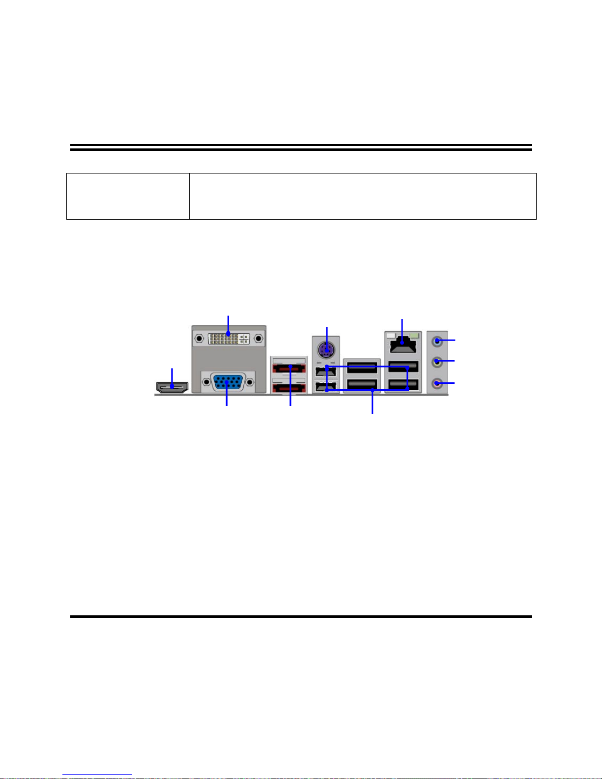
1-3 Layout Diagram
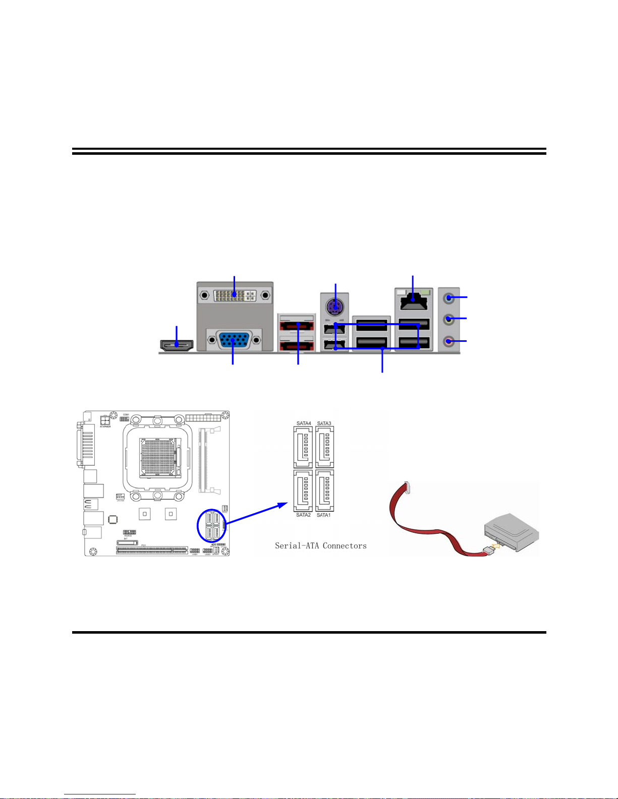
ESATA Connector
DVI
Connector
Line-In/
SPDIF OUT
USB Connector
Line-Out
HDMI
Connector
VGA
Connector
RJ45 LAN
MIC-IN
PS/2 Keyboard port
Page 9
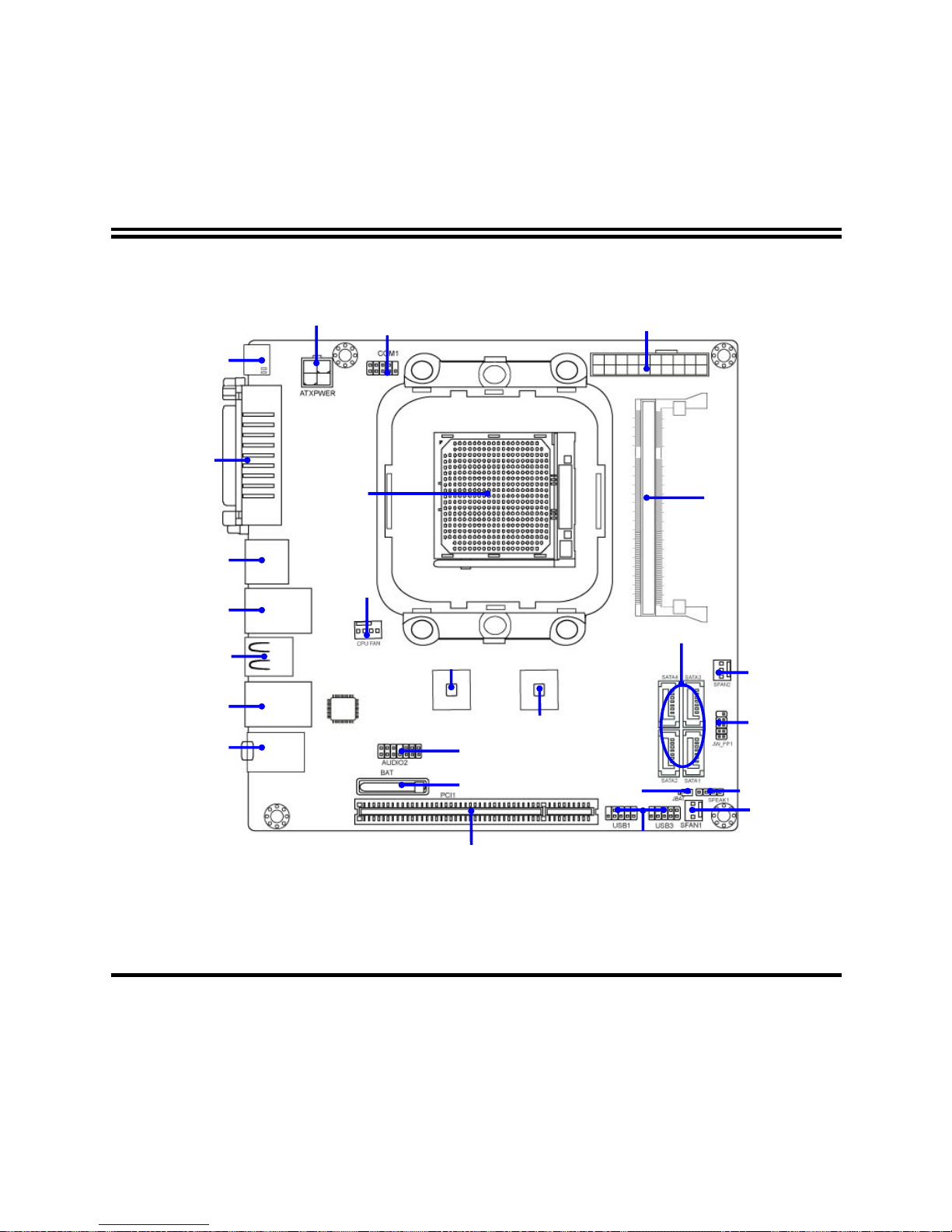
4
USB Headers
HDMI Connector
AMD SB750 Chipset
SYS FAN2
SATAII Connector
(1, 2, 3, 4)
ATX Power
Connector
ATX 12V Power
Connector
AMD 785G Chipset
COM1 Header
DDRII SODIMMB1
(DDRII 400/533/667/800)
JW_FP1 Header
Speak1 Header
SYSFAN1
CPUFAN
AUDIO2 Header
PCI Slot
DVI Connector
Over
VGA Connector
ESATA Connectors
Keyboard port
Over
USB Connectors
USB Connectors
RJ45 LAN port
Over
USB Connectors
Audio Connector
BAT
CPU Socket
Page 10
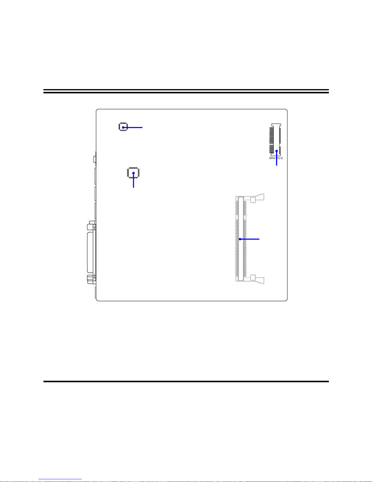
5
ALC662 HD Audio Codec
RTL8111DL Gigabit PCI-E
LAN Chip
DDRII SODIMMA1
MINIPCIEB1
Page 11

6
Jumper
Jumper Name Description
JBAT CMOS RAM Clear Function Setting 3-pin Block
Connectors
Connector Name Description
PW1
ATX Power Connector 20-pin Block
ATX12V
ATX 12V Power Connector 4-pin Block
HDMI
High-Definition Multimedia 19-pin Connector
DVI
Digital Visual Interface 24-pin Connector
VGA
D-Sub Connector 15-pin Connector
ESATA1
External Serial ATA2 Connectors 7-pin Connector
PS/2 Keyboard port
from UK1
PS/2 Keyboard Connector 6-pin Female
USB from
UK1,USB2,UL1
USB Port Connector 4-pin Connector
RJ45 LAN from UL1 RJ45 LAN Connector 8-pin Connector 8-pin Connector
AUDIO1 Line-Out, MIC, Line-In/SPDIF OUT
Connector
3 Phone Jack
SATA1,2,3,4 Serial ATAII Connectors 7-pin Connector
Headers
Header Name Description
USB1,USB3 USB2.0 Port Headers 9-pin Block
CPUFAN, SFAN1/2 FAN Speed Headers 3-pin Block
JW_FP1
(PWR LED/ IDE LED/
/Power Button /Reset)
Front Panel Headers
(PWR LED/ IDE LED/ /Power Button
/Reset)
9-pin Block
AUDIO2 Front panel audio Headers 13-pin block
COM1 Serial Port COM1 Header 9-pin Block
SPEAK1 PC Speaker connector 4-pin Block
Page 12
7
Chapter 2
Hardware Installation
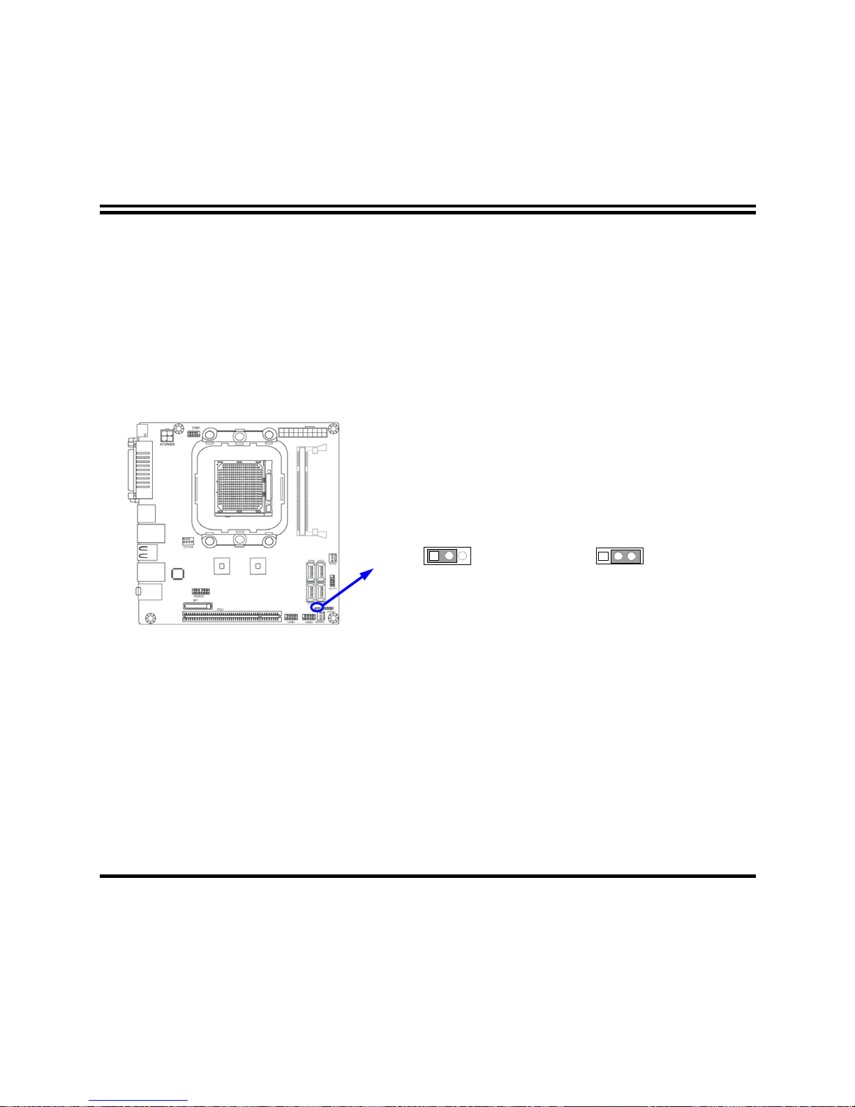
2-1 Jumper Setting
(1) Clear CMOS (3-pin): JBAT
CMOS RAM Clear Setting
2-3 closed Clear CMOS
JBAT JBAT
1-2 closed Normal
1
Page 13
8
2-2 Connectors and Headers
2-2-1 Connectors
(1) Audio Connector (Line-In /SPDIF OUT, Line-Out, MIC-In): AUDIO1
(2) Serial-ATA Port connector: SATAII 1/SATAII 2/SATAII 3/SATAII 4
ESATA Connector
DVI
Connector
Line-In/
SPDIF OUT
USB Connector
Line-Out
HDMI
Connector
VGA
Connector
RJ45 LAN
MIC-IN
PS/2 Keyboard port
Page 14

9
2-2-2 Headers
(1) Line-Out, MIC-In Header (13 pin): Front Panel Audio Header: AUDIO2
This header connects to Front Panel Line-out, MIC-In connector with cable.
Line-Out, MIC Headers
AUDIO2
Pin 1
AUD-Lineout2-L
AUD-MIC-R
AUD-Lineout2-R
SENSE-SEND
GN
D
SENSE2-RETUR
PRESENCE
2
KEY
AUD-MIC-L
SENSE1-RETURN
Line-in R
Line-in L Line-in JD
(2) USB Port Headers (9-pin): USB1/USB3
USB Port Header
VCC
Pin 1
-DATA
GND
+DATA
VCC
NC
-DATA
GND
+DATA
Page 15

10
(3) Front Panel Header: JW-FP1
System Case Connections
HDLED
RESET
VCC5
GND
PWRLED
PW R LED
PWRBTN
PWRBTN
GND
HDDLED
RSTSW
NC
GND
JW_FP1
Pin 1
(4) Speaker Header: SPEAK1
This 4-pin connector connects to the case-mounted speaker. See the figure below.
SPEAK1
SPEAK
NC
NC
VCC
Pin 1
Page 16

11
(5) Serial Port Header (9-Pin female): COM1
Serial CO M Port 9-pin Bl ock
DTR
Pin1Pin6
DCD
DSR
RXD
RTS
TXD
GND
GTS
RI
Pin5
(6) FAN Headers: CPUFAN (4 pin)
Pin 1: Ground
Pin 2:12V (fan power)
Pin 3: Detect (fan clock)
Pin 4: PWM (fan controller)
CPUFAN Header
1 4
Page 17

12
(7)FAN Speed Headers: SYSFAN1(3 pin), SYSFAN2 (3 pin)
Pin1: GND
Pin2: +12V fan power
Pin3: Fan Speed
1
3
SYSFAN2
1
3
SYSFAN1
Page 18

13
Chapter 3
Introducing BIOS
The BIOS is a program located on a Flash Memory on the motherboard. This program
is a bridge between motherboard and operating system. When you start the computer,
the BIOS program will gain control. The BIOS first operates an auto-diagnostic test
called POST (power on self test) for all the necessary hardware, it detects the entire
hardware device and configures the parameters of the hardware synchronization.
Only when these tasks are completed done it gives up control of the computer to
operating system (OS). Since the BIOS is the only channel for hardware and software
to communicate, it is the key factor for system stability, and in ensuring that your
system performance as its best.
In the BIOS Setup main menu of Figure 3-1, you can see several options. We will
explain these options step by step in the following pages of this chapter, but let us first
see a short description of the function keys you may use here:
•
Press <Esc> to quit the BIOS Setup.
•
Press ↑↓←→ (up, down, left, right) to choose, in the main menu, the option you
want to confirm or to modify.
•
Press <F10> when you have completed the setup of BIOS parameters to save
these parameters and to exit the BIOS Setup menu.
•
Press Page Up/Page Down or +/– keys when you want to modify the BIOS
parameters for the active option.
Page 19

14
3-1 Entering Setup
Power on the computer and by pressing <Del> immediately allows you to enter Setup.
If the message disappears before your respond and you still wish to enter Setup,
restart the system to try again by turning it OFF then ON or pressing the “RESET”
button on the system case. You may also restart by simultaneously pressing <Ctrl>,
<Alt> and <Delete> keys. If you do not press the keys at the correct time and the
system does not boot, an error message will be displayed and you will again be asked
to
Press <Del> to enter Setup
3-2 Getting Help
Main Menu
The on-line description of the highlighted setup function is displayed at the bottom of
the screen.
Status Page Setup Menu/Option Page Setup Menu
Press F1 to pop up a small help window that describes the appropriate keys to use
and the possible selections for the highlighted item. To exit the Help Window, press
<Esc>.
3-3 The Main Menu
Once you enter AMI ® BIOS CMOS Setup Utility, the Main Menu (Figure 3-1) will
appear on the screen. The Main Menu allows you to select from twelve setup
functions and two exit choices. Use arrow keys to select among the items and press
<Enter> to accept or enter the sub-menu.
Page 20

15
Figure 3-1
Standard CMOS Features
Use this Menu for basic system configurations.
Advanced BIOS Features
Use this menu to set the Advanced Features available on your system.
Advanced Chipset Features
Use this menu to change the values in the chipset registers and optimize your
system’s performance.
Integrated Peripherals
Use this menu to specify your settings for integrated peripherals.
Page 21

16
Power Management Features
Use this menu to specify your settings for power management.
Miscellaneous Control
Use this menu to specify your settings for Miscellaneous Control.
PC Health Status
This entry shows your PC health status.
Power User OverClock Settings
Use this menu to specify your settings (frequency, Voltage) for overclocking demand.
BIOS Security Features
Use this menu to set supervisor password and user password.
Load Optimal Defaults
Use this menu to load the BIOS default values these are setting for optimal performances
system operations for performance use.
Load Standard Defaults
This menu uses a minimal performance setting, but the system would run in a stable
way.
Save Changes and Exit
Save CMOS value changes to CMOS and exit setup.
Discard Changes and Exit
Abandon all CMOS value changes and exit setup.
3-4 Standard BIOS Features
The items in Standard CMOS Setup Menu are divided into several categories. Each
category includes no one or more than one setup items. Use the arrow keys to
highlight the item and then use the <PgUp> or <PgDn> keys to select the value you
want in each item.
Page 22

17
Date
The date format is <day><month><date><year>.
Day
Day of the week is from Sun to Sat, determined by BIOS. Read-only.
Month
The month is from Jan. through Dec.
Date
The date from 1 to 31 can be keyed by numeric function keys.
Year
The year depends on the year of the BIOS.
Time
The time format is <hour><minute><second>.
SATA Channel 1, 2, 3, 4, 5, 6
While entering setup, BIOS auto detects the presence of IDE devices. This displays
the status of auto detection of IDE devices.
Page 23

18
Type
The optional settings are: Not Installed; Auto; CD/DVD and ARMD. Use the item to
select the type of device connected to the system.
LBA/Large Mode
The optional settings are Auto; Disabled.
Disabled: disables LBA mode.
Auto: enables LBA Mode if the devices support it and the device is not already
formatted with LBA Mode disabled.
Block (Multi-Sector Transfer)
The optional settings are: Disabled and Auto.
Disabled: The Data transfer from and to the device occurs one sector at a time.
Auto:The Data transfer from and to the device occurs multiple sectors at a time if the
device supports it.
PIO Mode
The optional settings are: Auto, 0, 1, 2, 3 and 4.
DMA Mode
The optional settings are Auto, SWDMAn, MWDMAn, UDMAn.
S.M.A.R.T.
This option allows you to enable the HDD S.M.A.R.T Capability (Self-Monitoring,
Analysis and Reporting Technology). The optional settings are Auto; Disabled and
Enabled.
32 Bit Data Transfer
The optional settings are: Disabled and Enabled.
Page 24

19
3-5 Advanced BIOS Features
Removable Drives---1st Drive
Use this item to specify the boot device priority sequence from available drives.
Quick Boot
Use the item to allow BIOS to skip certain tests while booting. This will decrease the
needed to boot the system.
1st Boot Device
Specify the boot sequence from the available devices. A device enclosed in
parenthesis has been disabled in corresponding type menu.
Bootup Num-Lock
The default value is On.
On
(default)
Keypad is numeric keys.
Off
Keypad is arrow keys.
Page 25

20
ACPI APIC Support
Include ACPI APIC table pointer to RSDT pointer list. The optional settings are:
Disabled and Enabled.
MPS Revision
This option is only valid for multiprocessor motherboards as it specifies the version of
the Multiprocessor Specification (MPS) that the motherboard will use.
F11 Boot Menu
The optional settings are: Disabled and Enabled.
3-5-1 CPU Configuration
GART Error Reporting
This option should remain disabled for the normal operation. The driver developer
may enable it for testing purpose.
Page 26

21
Microcode Update
Enable/disable Secure Virtual Machine Mode (SVM).The optional settings are:
Disabled and Enabled.
3-6 Advanced Chipset Features
The Advanced Chipset Features Setup option is used to change the values of the
chipset registers. These registers control most of the system options in the computer.
HDMI Audio
The optional settings are: Disabled; Enabled.
NB Power Management Features
Dynamic clock gating for ION/NT/MCU/CFG. The optional settings are: Auto;
Disabled.
Page 27

22
3-6-1 Memory Configuration
DRAM Timing Mode
The optional settings are: Auto; DCT 0; DCT1; Both.
Bank Interleaving
Use this item to enable bank memory interleaving. The optional settings are: Auto;
Disabled.
Enable Clock to ALL DIMMs
Enable unused clocks to DIMMS when memory slots are not populated.
Mem CLK Tristate during C3 and Alt VID.
Enable and disable Mem CLK Tri-stating during C3 and Alt VID
Memory Hole Remapping
Page 28

23
Enable Memory Remapping around Memory Hole.
DCT Unganged Mode
This allows selection of unganged DRAM MODE (64- bit width).
Auto=Ganged Mode; Always= Unganged Mode.
Power Down Enable
Enable or Disable DDR power down mode.
3-6-2 Internal Graphics Config
Internal Graphics Mode
The optional settings are: Disabled; UMA; SIDEPORT; UMA+SIDEPORT.
Page 29

24
UMA Frame Buffer Size
The optional settings are: Auto; 32MB; 64MB; 128MB; 256MB; 512MB.
FB Location
The optional settings are: Below 4G; Above 4G.
3-6-3 PCI Express Configuration
Port #04 Features ~ Port #06Features
Press Enter and set values in the sub-items as Gen2 High Speed Mode, Link ASPM.
NB-SB Port Features
Press Enter and set values in the sub-items as NB-SB Link ASPM; NP NB-SB VC1
Traffic Support and Link Width.
Page 30

25
3-7 Integrated Peripherals
3-7-1 Onboard SATA Device
OnChip SATA Channel
Press Enter to enable or disable OnChip SATA Channel.
0n Chip SATA Type
Press Enter to select the OnChip SATA type. The optional settings are: Native IDE;
RAID; AHCI; Legacy IDE; IDE->AHCI.
SATA IDE Combined Mode
The optional settings are: Enabled; Disabled.
Hard Disk Write Protect
Disables /Enables device write protection. This will be effective only if device is
Page 31

26
accessed through BIOS.
IDE Detect Time Out (Sec)
Select the time out value for detecting ATA/ATAPI device(s). The optional settings are:
0; 5; 10; 15; 20; 25; 30; 35.
SATA Run Mode Configuration
The optional settings are: Compatible; Enhanced.
3-7-2 Onboard Device Control
Onboard PCI E Lan Device
Use this item to enable or disable Onboard PCI E Lan.
Onboard Lan Boot ROM
This enables or disables PXE Function.
HD Audio Azalia Device
This item allows you to decide to enable/disable the chipset family to support HD
Audio. The optional settings are: Auto; Enabled and Disabled.
USB Configuration
Press Enter to set values for sub-items as: Legacy USB Support, USB 2.0 Controller
Mode; BIOS EHCI Hand-off etc.
Page 32

27
3-7-3 Super IO Configuration
Serial Port1 Address
Use this item to allow BIOS to select serial port1 Base Addresses. Press Enter to set
values for sub-items as: serial port1 Address, PWROM After PWR-fail; WatchDog
Timer Select.
PWROM After PWR-Fail
The optional settings are: Former-Sts; Always On; Always Off.
WatchDog Timer Select
This item is used to activate the watchdog function. The optional settings are:
Disabled; Enabled.
Eup Function Support
Page 33

28
The optional settings are: Disabled; Enabled.
3-8 Power Management Features
The Power Management Setup allows you to configure your system to most
effectively save energy saving while operating in a manner consistent with your own
style of computer use.
Suspend Mode
Use this item to select the ACPI state used for System Suspend. The optional settings
are: S1 (POS); S3 (STR).
Power Management/APM
Use this item to enable or disable SMI based power management and APM support.
Suspend Time Out
If it is set Enabled and no activity during this time period, the BIOS will place the
system into suspend low power state. The optional settings are: Disabled; 1~64
minutes.
Page 34

29
Power Button Mode
The optional settings are: On/Off; Suspend.
Video Power Down Mode
The optional settings are: Disabled; Standby and Suspend.
Hard Disk Power Down Mode
The optional settings are: Disabled; Standby and Suspend.
Hard Disk Time Out
The optional settings are: Disabled; 1~15 minutes.
PowerOn by PCI Card
Use this item to enable or disable PCI card to generate a wake event.
Wake-up by PCIE
Use this item to enable or disable LAN GPI to generate a wake event.
RTC Resume
Use this item to enable or disable RTC to generate a wake event.
3-9 Miscellaneous Control
Page 35

30
Clear NVRAM
Use the item to clear NVRAM during System Boot. The optional settings are: No; Yes.
Plug &Play O/S
The optional settings are: No; Yes
No: Let the BIOS configure all the devices in the system.
Yes: Let the operating system configure Plug and Play devices, not required for boot if
your system has a Plug and Play system.
PCI Latency Timer
Value in units of PCI clocks for PCI device latency timer register.
Allocate IRQ for PCI VGA
The optional settings are: No; Yes.
Yes: Assigns IRQ to PCI VGA card if card requests IRQ.
No: Does not assign IRQ to PCI VGA card even card requests an IRQ.
Palette Snooping
The optional settings are: Enabled; Disabled.
Enable: inform the PCI device that an ISA graphics devices is installed in the system
so the card will function correctly.
PCI IDE Bus Master
The optional settings are: Enabled; Disabled.
Enable: BIOS uses PCI busmastering for reading/writing IDE devices.
Offboard PCI/ISA IDE Card
Some PCI IDE cards may require this to be set to the PCI slot number that is holding
the card.
IRQ Resources
Press Enter to set values for sub-items as: IRQ5; IRQ7; IRQ9; IRQ10; IRQ11; IRQ14;
IRQ15.
Page 36

31
3-10 PC Health Status
This section shows the Status of you CPU, Fan, and Warning for overall system status.
This is only available if there is Hardware Monitor onboard.
H/W Health Function
It displays information list below when set as below. The choice is either Enabled and
Disabled.
CPU Temperature/SYS Temperature/CPUFAN Speed/SYSFAN1 Speed /VCORE
/NB1V2 /VDIMM/3VSYS/5VSYS
This will show the CPU/ /System voltage chart and FAN Speed, etc.
SmartFan Setting
Page 37

32
The optional settings are: Auto Fan by Dutycycle; Disabled.
CPU Temperature Limit
Use this item to set CPU temperature setting. Min=0 ; Max=127℃℃.
3-11 Power User OverClock Settings
CPU/HT Reference Clock
Use this item to set CPU/HT Reference Clock.
PCI E Reference Clock
Use this item to set PCI E Reference Clock.
SB Reference Clock
Use this item to set SB Reference Clock.
Processor Frequency Multipier
Page 38

33
The optional settings are: Auto; x4.0~x10.5.
Processor Voltage
The optional settings are: Auto; 0.800v~1.125v.
AOD Compatibility
Choose Enabled means only AMD over drive can adjust voltage
Choose Disabled means only BIOS can adjust voltage.
VDIMM Select
Use this item to select VDIMM value. The optional settings are: 1.85v; 1.90v; 1.95v;
2.00v.
N Voltage Setting
The optional settings are: 1.10v; 1.15v; 1.20v.
HT Link Speed
The Hyper Transport link will run at this speed if it slower than or equal to system
clock and this board is capable. The optional settings are from Auto;
200MHz~1.8GHz.
HT Link Width
The Hyper Transport link will run at this width. The optional settings are Auto; 4 Bit; 8
Bit; 16 Bit.
DRAM Command Rate
The optional settings are: Auto; 1T; 2T.
Memory Clock Mode
The optional settings are: Auto; Limit and Manual.
Page 39

34
3-12 BIOS Security Features
You can set either supervisor or user password or both of them. The differences
are:
Supervisor password: Can enter and change the options of the setup menus.
User password: Can only enter but do not have the right to change the options of
the setup menus. When you select this function, the following message will appear
at the center of the screen to assist you in creating a password.
ENTER PASSWORD
Type the password up to eight characters in length, and press <Enter>. The
password typed now will clear any previously entered password from CMOS
Page 40

35
memory. You will be asked to confirm the password. Type the password again
and press <Enter>. You may also press <Esc> to abort the selection and not enter
a password.
To disable a password, just press <Enter> when you are prompted to enter the
password. A message will confirm that the password will be disabled. Once the
password is disabled, the system will boot and you can enter Setup freely.
PASSWORD DISABLED
When a password has been enabled, you will be prompted to enter it every time
you try to enter Setup. This prevents an unauthorized person from changing any
part of your system configuration.
Additionally, when a password is enabled, you can also require the BIOS to
request a password every time your system is rebooted. This would prevent
unauthorized use of your computer.
You determine when the password is required within the BIOS Features Setup
Menu and its Security option. If the Security option is set to “System”, the
password will be required both at boot and at entry to Setup. If set to “Setup”,
prompting only occurs when trying to enter Setup.
Boot Sector Virus Protection
The selection allows you to choose the VIRUS Warning feature for IDE Hard Disk
boot sector protection. If this function is enabled and someone attempt to write
data into this area, BIOS will show a warning message on screen and alarm beep.
Disabled (default) No warning message to appear when anything attempts to
access the boot sector or hard disk partition table.
Enabled Activates automatically when the system boots up causing a warning
message to appear when anything attempts to access the boot sector of hard disk
partition table.
Page 41

36
3-13 Load Optimal Defaults /Load Standard Defaults
Load Optimal Defaults
When you press <Enter> on this item, you get a confirmation dialog box with a
message similar to:
Pressing <OK> loads the default values that are factory settings for optimal
performance system operations.
Load Standard Defaults
When you press <Enter> on this item, you get a confirmation dialog box with a
message similar to:
Pressing <OK> loads the default values that are factory settings for stable
performance system operations.
Page 42

37
3-14 Save Changes and Exit / Discard Changes and Exit
Save Changes and Exit
When you press <Enter> on this item, you get a confirmation dialog box with a
message similar to:
Pressing <OK> save the values you made previously and exit BIOS setup.
Discard Changes and Exit Setup?
When you press <Enter> on this item, you get a confirmation dialog box with a
message similar to:
Pressing <OK> to leave BIOS setting without saving previously set values.
Notice! The BIOS options in this manual are for reference only. Different
configurations may lead to difference in BIOS screen and BIOS
screens in manuals are usually the first BIOS version when the board is
released and may be different from your purchased motherboard.
Users are welcome to download the latest BIOS version form our
official website.
 Loading...