

JETWAY JDL108G-4F-M, JDL108GP-4F-M User Manual

JDL108G-4F-M
&
JDL108GP-4F-M
(PoE support)
Industrial Managed Switch
User's Guide

Directories
Chapter 1 Product Introduction ........................................................................................................................................ 1
1.1 Overview ........................................................................................................................................................... 1
1.2 BOM .................................................................................................................................................................. 1
1.3 Switch Panel Descriptions ................................................................................................................................ 1
1.4 Performance Characteristics ............................................................................................................................. 3
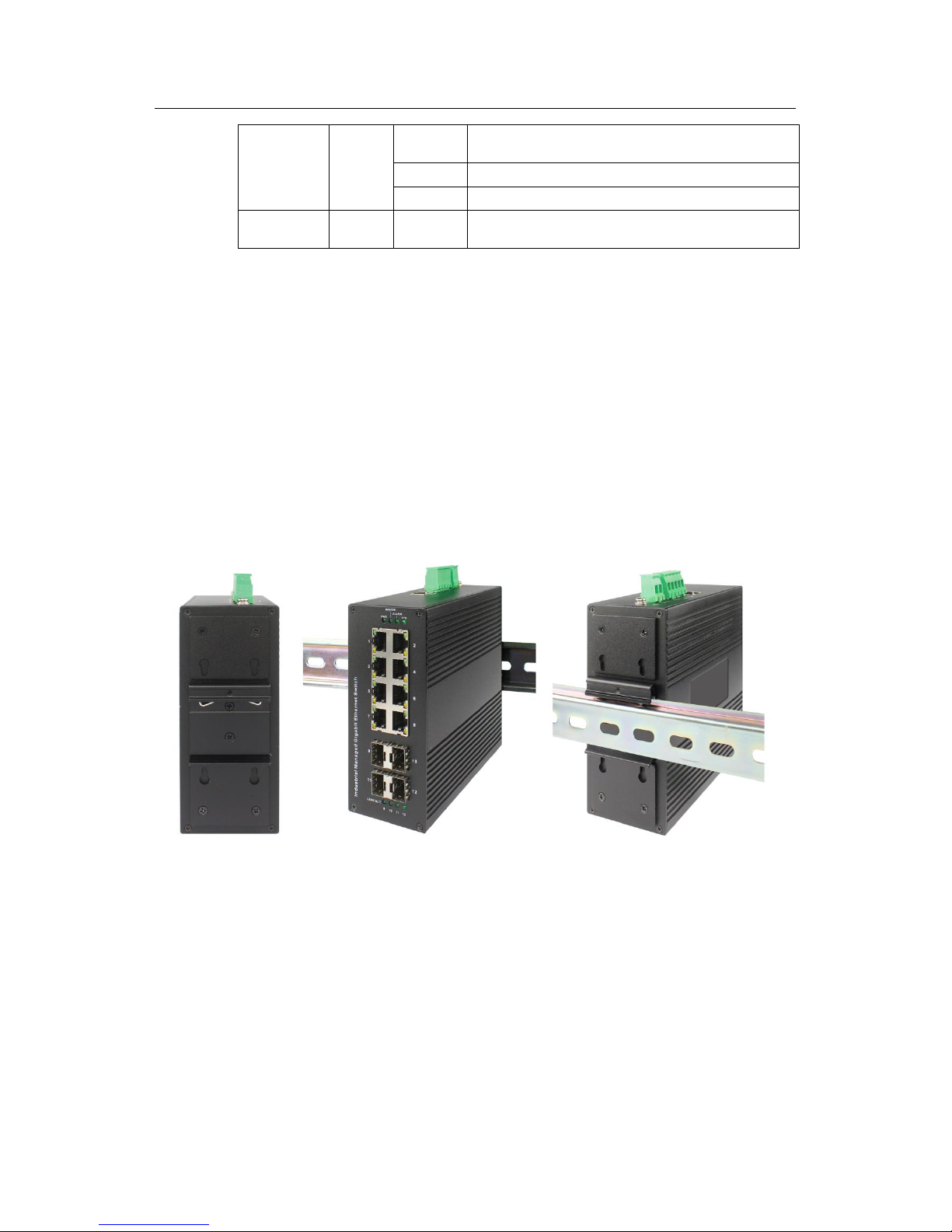
1.5 DIN Rail Type .................................................................................................................................................... 3
Chapter 2 Installation ....................................................................................................................................................... 4
2.1 Installation Method ............................................................................................................................................ 4
2.2 Switch Port to a Network Terminal Interface ..................................................................................................... 4
2.3 Power Supply .................................................................................................................................................... 4
2.4 Factory Default Settings .................................................................................................................................... 4
Chapter 3 Getting Started ................................................................................................................................................ 6
3.1 Management Options ........................................................................................................................................ 6
3.2 Using Web-based Management ........................................................................................................................ 6
Chapter 4 Chapter 4 Configuration .................................................................................................................................. 8
4.1 Welcome ........................................................................................................................................................... 8
4.2 System Configuration ........................................................................................................................................ 9
4.3 Port Configuration ........................................................................................................................................... 14
4.4 MAC Binding ................................................................................................................................................... 18
4.5 MAC Filter ....................................................................................................................................................... 19
4.6 VLAN Configuration ........................................................................................................................................ 20
4.7 SNMP Configuration ....................................................................................................................................... 22
4.8 ACL Configuration ........................................................................................................................................... 23
4.9 QOS Configuration .......................................................................................................................................... 26
4.10 IP Basic Configuration ................................................................................................................................... 27
4.11 AAA Configuration ......................................................................................................................................... 28
4.12 MSTP Configuration ...................................................................................................................................... 30
4.13 IGMP SNOOPING Configuration .................................................................................................................. 32
4.14 GMRP Configuration ..................................................................................................................................... 33
4.15 EAPS Configuration ...................................................................................................................................... 34
4.16 Log Management .......................................................................................................................................... 35
4.17 POE Power Control ....................................................................................................................................... 36
-1-
Chapter 1 Product Introduction
1.1 Overview
Switch provide 8*100/1000M ports and 4* 1000M SFP optical ports ( SC or ST module
is optional), to make your network more flexible, secure, reliable, internal embedded
WEB CLI management can make your network management more comfortable. Switch
support console management and telnet management.
1.2 BOM
●
Switch*1
●
Serial line*1
●
Manual*1
Note:Please contact your local representative, if any of the default items is missing,
after opening the product packaging cartons
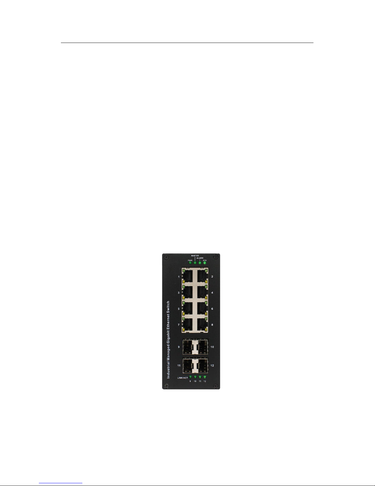
1.3 Switch Panel Descriptions
1.3.1 The front panel
1-3-1, Switch front panel has 8*port connection status LED and PoE status indicators ,
power indicator; system indicator. There are 8* RJ45 ports and 4* 1000M/SFP optical
ports.
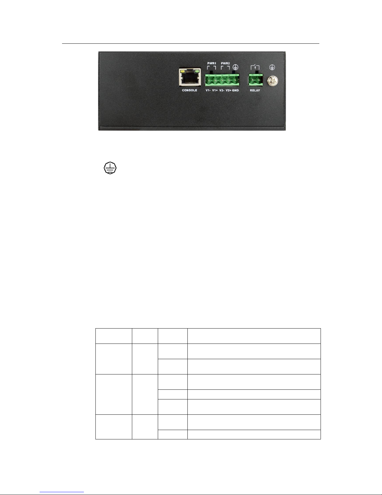
Power Interface:
Power supply range: DC48V @ 2.5A (range: DC45 ~ 60V)
-2-
‘
1-3-2
Phoenix terminal definition:
1---
:
Grounding
2---REALY: Alarm contacts for the loss of power
3----V2+ :DC Power Input the positive electrode
4----V2- :DC Power input negative electrode
5----V1+ :DC Power Input the positive electrode
6----V1- :DC Power input negative electrode
Note:
1.Power failure alarm contact definition: power outages, the contact is closed, the
power contacts are disconnected.
Contact load: 2A 30DC or 0.5A 125VAC
2. reversed after the device does not work.
1.3.2 Indicator Description
On the front panel indicators are used for monitoring the running state of equipment,
the table follow is the indicator status and description for common fault:
LED
Indicator
Color
Status
Description
PWR
Green
(Yellow)
Lights
After the switch connected to the power, DC power supply
input for the V+, V-contacts
Extinguish
Check if the AC power connector is loose, or power cord
is intact
Link/Act
Yellow
Lights
The switch network device interface is properly
connected to a port, the corresponding indicator lights
Flashing
Port if the data stream, the corresponding port Flashing
Extinguish
Check if the connection of the network cable is intact, or
the joint is loose
POE
Green
Lights
When there is compliance IEEE802.3af & at the PD
device access time
Extinguish
Non-PD devices or non-compliant equipment
-3-
Link/Act
(SFP)
Green
Lights
When the Gigabit optical modules connected to a port,
the corresponding indicator lights
Flashing
Port if the data stream, the corresponding port Flashing
Extinguish
Non-Gigabit optical modules device connected to the port
MASTER
Green
Flashing
Only if when switch enable EAPS function, and be
configured master mode
1.4 Performance Characteristics
Characteristics:
●
Intelligent Managed
●
8*100/1000M RJ45 ports, support POE power supply, each port output 30w, follow
IEEE802.3at Power over Ethernet standard, 1/2/3/6 feet powered
●
4* 1000M optical port (SFP)
●
Topology: star, support RSTP, EAPS
●
Humidity (non-condensing): 10% -95%
●
Operating temperature: -40 ℃ +75 ℃
DIN Rail Type

-4-
Chapter 2 Installation
2.1
Installation Method
Do not place heavy objects on the switch body
Carefully check the power supply, verify that the connection is made securely
The device has enough space for ventilation around to ensure good heat dissipation.
2.2 Switch port to a network terminal interface
The RJ45 ports support PoE switches automatically flip, all available through twisted
pair UTP ports (3,4,5 UTP straight-through or crossover cables) and the network
terminal device interface (such as a PC card) connection. Cable does not exceed 100m.
If the connection indicator status is abnormal, check the configuration of the network.
interface card, cable connections, and switch port working mode. Properly connected,
the switch status indicator may be: (1) Link / Act LED remains lit in a connected state or
flashing; (2) port in POE power supply mode, Green lights.
2.3 Power supply
You can use the switch voltage DC45 ~ 60V, 2.5A MAX. Within the permitted
operating voltage range, the power switch will automatically adjust according to the
external power supply voltage to ensure stable operation of the switch. In the absence
of any network connection.
2.4 Factory default settings
Web: IP address: 192.168.0.1 Username: admin Password: admin
Console: 9600 8-N-1

-5-
Chapter 3 Getting Started
This chapter introduces the management interface of the switch.
3.1 Management Options
The Switch can be managed through any port on the device by using the Web-based
Management.
Each switch must be assigned its own IP Address, which is used for communication
with Web-Based Management. The PC’s IP address should be in the same range as
the switch. Each switch can allow only one user to access the Web-Based
Management at a time.
Please refer to the following installation instructions for the Web-based Management.
3.2 Using Web-based Management
After a successful physical installation, you can configure the switch, monitor the
network status, and display statistics using a web browser.
Connecting to the Switch
You will need the following equipment to begin the web configuration of your device:
A PC with a RJ-45 Ethernet connection
A standard Ethernet cable
Connect the Ethernet cable to any of the ports on the front panel of the switch and to
the Ethernet port on the PC.
Login Web-based Management
In order to login and configure the switch via an Ethernet connection, the PC must have
an IP address in the same subnet as the switch. For example, if the switch has an IP
address of
192.168.0.1,
the PC should have an IP address of
192.168.0.1x
(where x is
a number between 2 ~ 254), and a subnet mask of
255.255.255.0
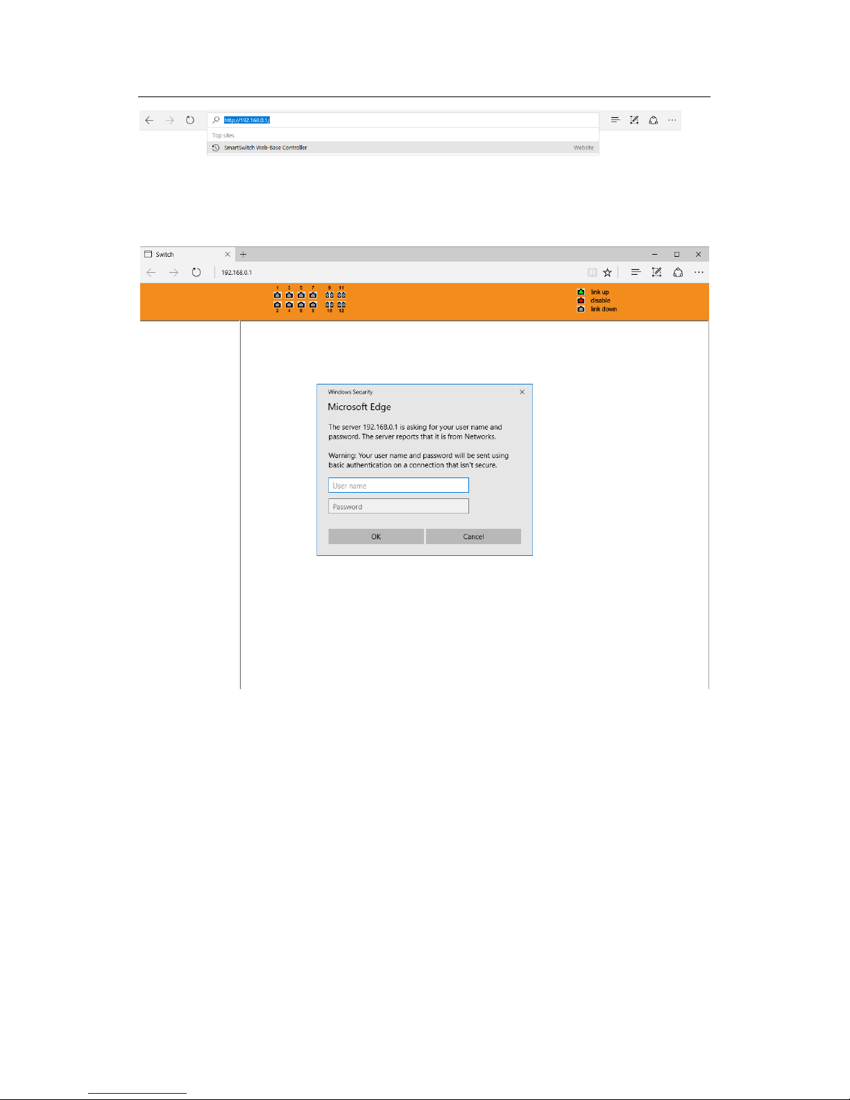
. Open the web
browser and enter
192.168.0.1
(the factory-default IP address) in the address bar. Then
press <Enter>.
-6-
When the following logon dialog box appears, enter the user name and password then
click OK. The default user name is
admin
and password is
admin
.
-7-
Chapter 4 Configuration
The features and functions of the switch can be configured for optimum use through the
Web-based Management.
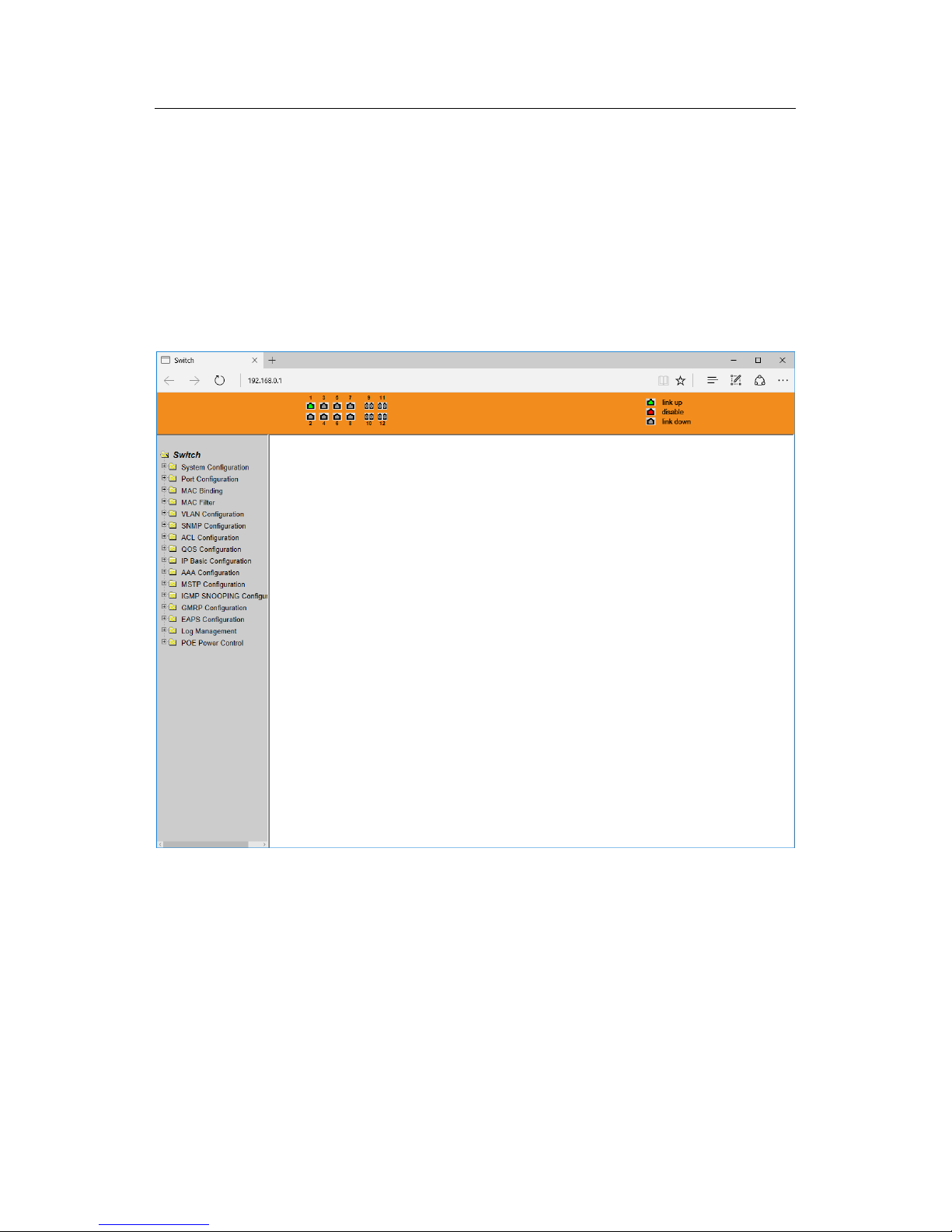
4.1 Welcome
After a successful login you will see the screen as below:
-8-
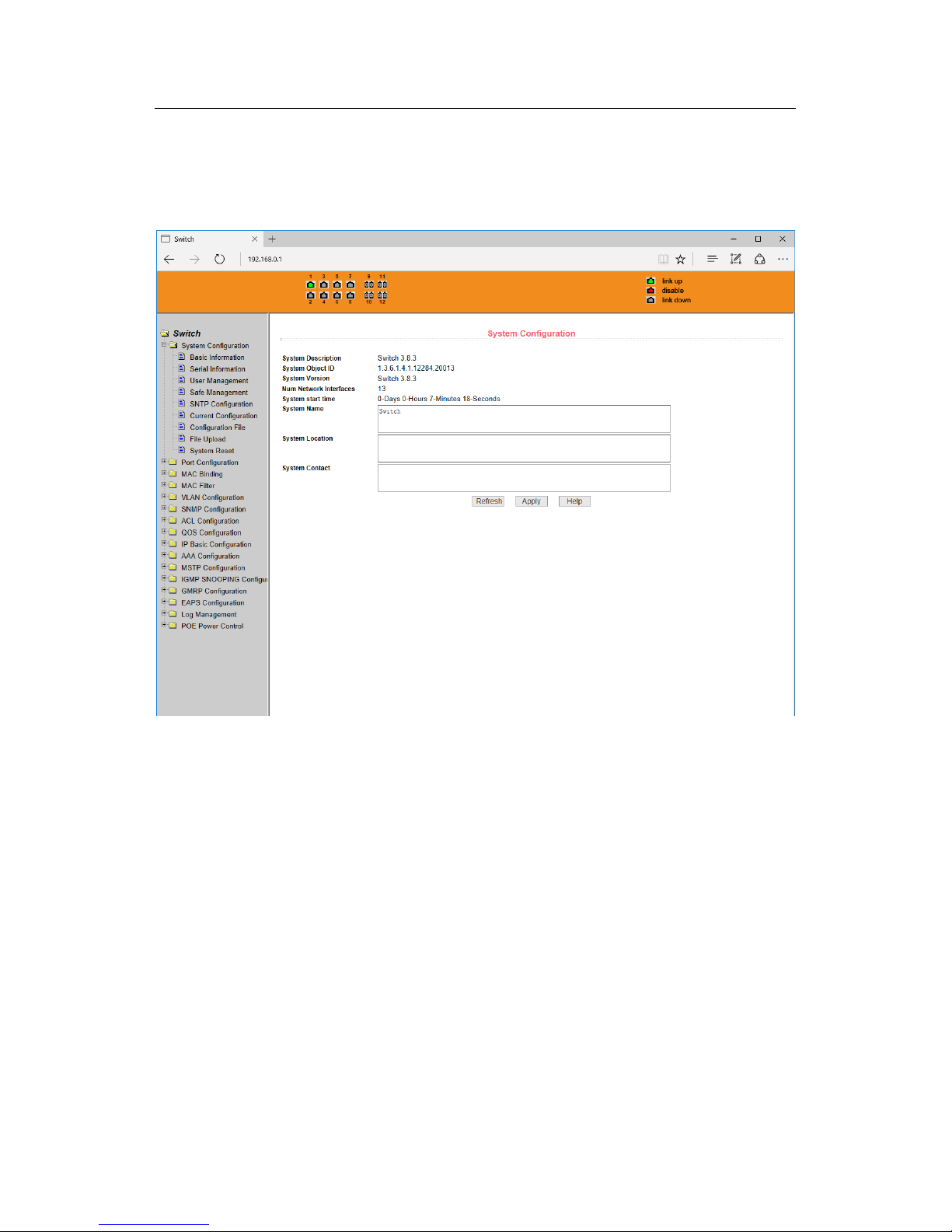
4.2 System Configuration
Basic Information:
-9-
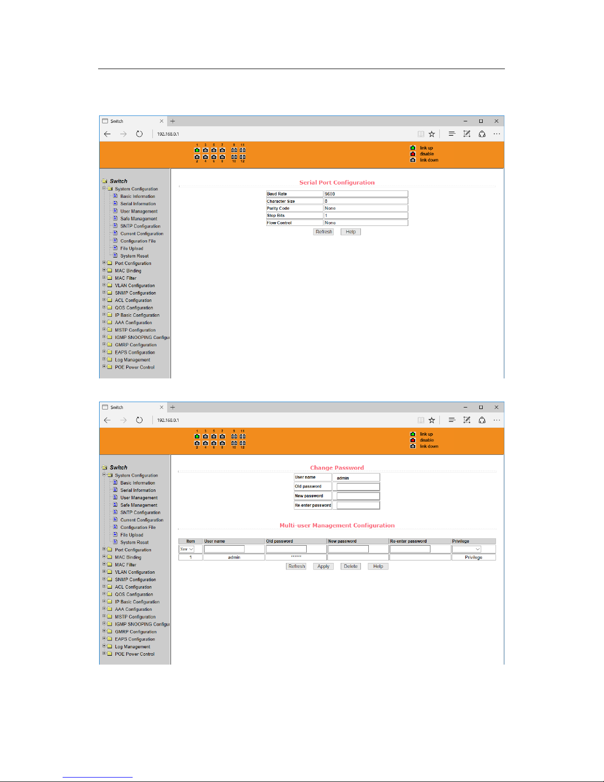
Serial Information:
User Management:
-10-
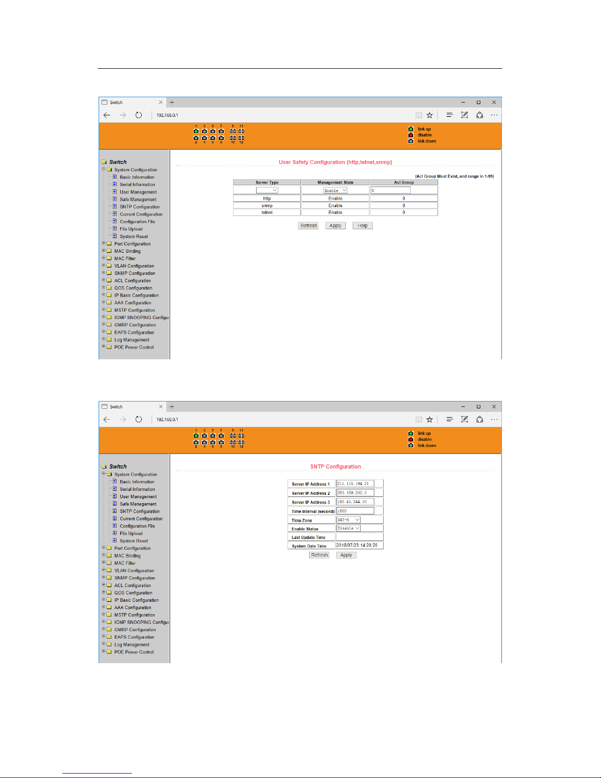
Safety Management:
SNTP Configuration:
 Loading...