

Page 1

JDL105G
Industrial Switch
User's Guide
Page 2

Directories
Chapter 1 Product Introduction ........................................................................................................................................ 1
1.1 Overview ........................................................................................................................................................... 1
1.2 BOM .................................................................................................................................................................. 1
1.3 Switch Panel Descriptions ................................................................................................................... 1
1.3.1 The Front Panel .................................................................................................................................... 1
1.3.2 Indicator Description ............................................................................................................................. 2
1.4 Performance Characteristics........................................................................................................................... 2
1.5 DIN Rail Type .................................................................................................................................................. 2
Chapter 2 Installation ....................................................................................................................................................... 3
2.1 Installation Method ............................................................................................................................................ 3
2.2 Switch Port to a Network Terminal Interface ..................................................................................................... 3
Page 3
- 1 -
Chapter 1 Product Introduction
1.1 Overview
Switch provides 5* 100/1000M RJ45 ports to make your network more flexible, secure
and reliable.
1.2 BOM
●
Switch*1
●
Manual*!
Note:Please contact your local representative, if any of the default items is missing,
after opening the product packaging cartons
1.3 Switch Panel Descriptions
1.3.1 The front panel
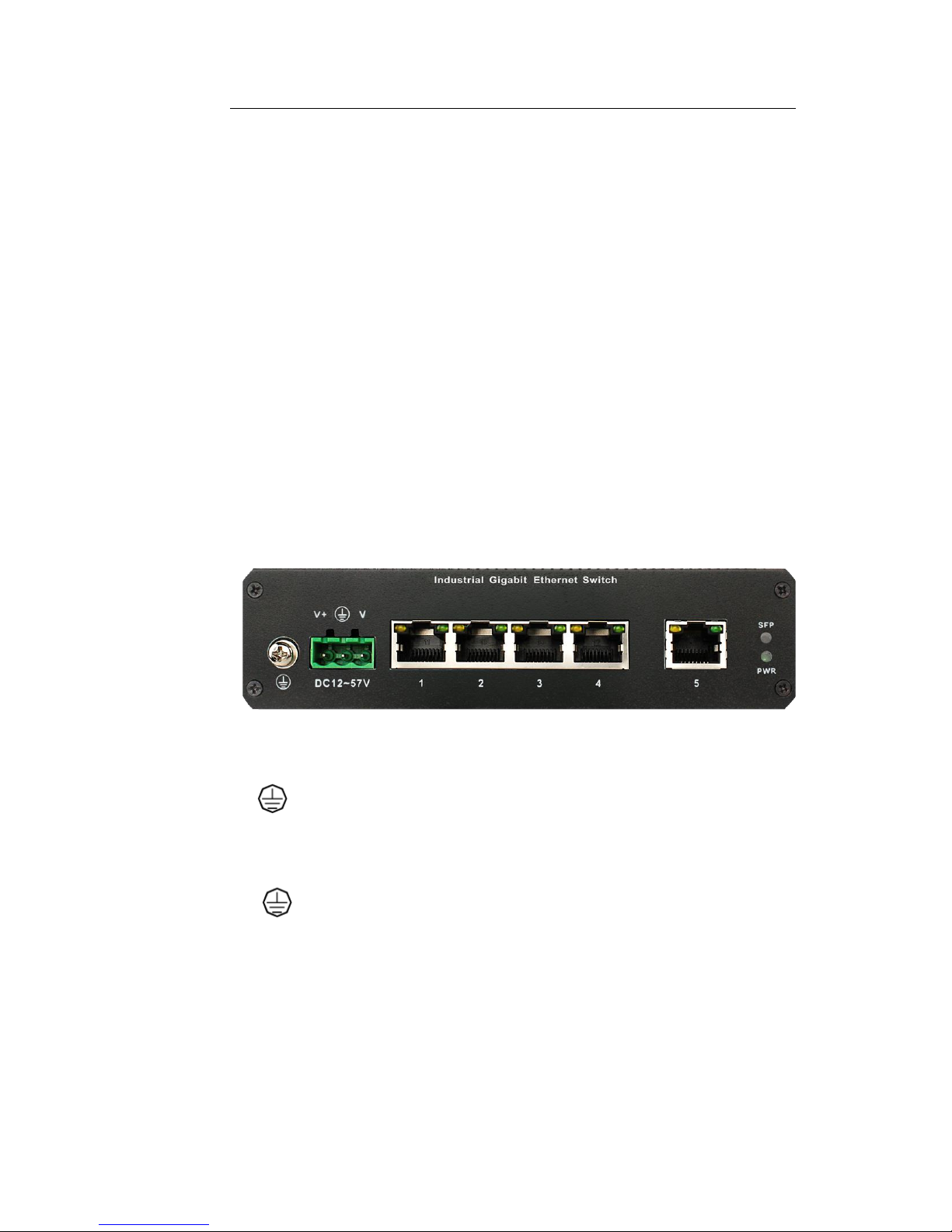
1-3-1, The front panel has 5*port connection status LED, power
indicator,1*PHOENIX,1* DC2.0 power Interface, power indicator, 1* grounding screw.
Phoenix terminal definition:
1---
:
Grounding
2---V+:DC Power Input the positive electrode
3----V-:DC Power input negative electrode
4---- : Not Connected
Note: reversed after the device does not work
.
Switch comes with anti-protection. Within the permitted operating voltage range,
the switch will automatically adjust according to the external power supply
voltage to ensure stable operation.
Page 4
- 2 -
1.3.2 Indicator Description
On the front panel indicators are used for monitoring the running state of equipment,
the table follow is the indicator status and description for common fault:
LED Indicator
Color
Status
Description
PWR
Green
(Yellow)
Lights
After the switch connected to the power, DC power
supply input for the V +, V-contacts
Extinguish
Check if the AC power connector is loose, or power
cord is intact
Link/Act
Yellow
Lights
The switch network network device interface is
properly connected to a port, the corresponding
indicator light
Flashing
Port if the data stream, the corresponding port
Flashing
Extinguish
Check if the connection of the network cable is
intact, the joint is loose
1.4 Performance Characteristics
Characteristics:
●
5* 100/1000M copper port (RJ45)
●
Humidity (non-condensing): 10% ~ 95%.
●
Operating temperature:-40 ℃ ~ 85 ℃.
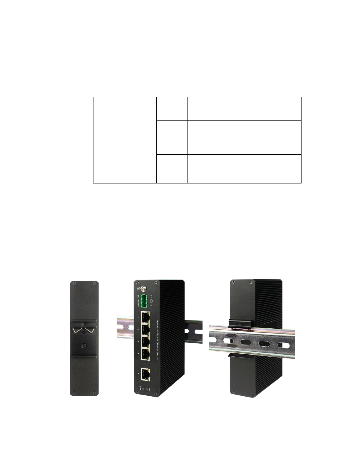
1.5 DIN Rail Type
Page 5
- 3 -
Chapter 2 Installation
2.1
Installation Method
Do not place heavy objects on the switch body.
Carefully check the power supply, verify that the connection is made securely.
The device has enough space for ventilation around to ensure good heat dissipation.
2.2 Switch port to a network terminal interface
The RJ45 ports support switches automatically flip, all available through twisted pair
UTP ports (3,4,5 UTP straight-through or crossover cables) and the network terminal
device interface (such as a PC card) connection. Cable does not exceed 100m. If the
connection indicator status is abnormal, check the configuration of the network. interface
card, cable connections, and switch port working mode. Properly connected, the switch
status indicator may be: Link / Act LED remains lit in a connected state or flashing;
 Loading...