

Page 1

993AS-L/993AS
/993AN
USER'S MANUAL
PCIAGP Mainboard
For
Pentium II/
III or Socket 370
The author assumes no responsibility for any errors or omissions which
may appear in this document nor does it make a commitment to update
the information contained herein.
Release date: NOV 2000
NO. G03-993ANR3A
** Year 2000 compliant **
Trademark:
* Pentium is registered trademark and MMX is a trademark of Intel corporation,
the other names and brands are the property of their respective owners.
* Specifications and Information contained in this documentation are furnished for information use only, and are subject to
change at any time without notice, and should not be construed as a commitment by manufacturer.
Page 2

Chapter 1
1-1 Preface............................................................................................................. 1
1-2 Feature of motherboard ................................................................................... 1
1-2-1 Overview.............................................................................................. 1
1-2-2 Key Feature......................................................................................... 2
TABLE OF CONTENT
Chapter 2
Hardware Installation
2-1 Unpacking ........................................................................................................ 3
2-2 Mainboard Diagram.......................................................................................... 4
2-3 Quick Reference for Jumpers, Connectors & Expansion Socket....................... 5
2-4 Installation Steps.............................................................................................. 6
2-5 Jumper Settings ............................................................................................... 6
2-6 System Memory (DRAM).................................................................................. 7
2-7 Central Processing Unit (CPU)......................................................................... 7
2-8 Expansion Cards.............................................................................................. 11
2-9 External Connectors......................................................................................... 11
..................................................................................3
Chapter 3
AWARD BIOS SETUP
3-1 STANDARD CMOS SETUP ............................................................................. 19
3-2 BIOS FEATURES SETUP................................................................................ 20
3-3 CHIPSET FEATURES SETUP......................................................................... 21
3-4 POWER MANAGE MENT SETUP ................................................................... 22
3-5 PnP/PCI CONFIGURATION SETUP ............................................................... 24
3-6 LOAD OPTIMAL DEFAULTS ........................................................................... 24
3-7 LOAD STANDARD DEFAULTS .......................................................................25
3-8 INTEGRATED PERIPHERALS SETUP............................................................ 25
3-9 SUPERVISOR/USER PASSWORD ................................................................. 26
3-10 SAVE & EXIT SETUP ..................................................................................... 26
3-11 EXIT WITHOUT SAVING................................................................................ 26
..................................................................................18
Chapter 4
Software Installation......................................................................... 27
4-1 Mainboard Driver Install in Win9X,WinNT ........................................................ 27
4-2 PC HEALTH MONITOR-III (
4-3 SOUND Driver (Option for motherboard that embedded Audio chip)................ 30
Option for motherboard that embedded PC Health chip)...... 28
APPENDIX-A Magic Install
i
Page 3

Chapter 1
1-1 Preface
Thank you for purchasing this multifunction motherboard. It has the most flexibility you can find
in today’s computer market. The mainboard integrates both Intel Pentium®II / Pentium®III &
Celeron™(Slot 1 & Socket 370) processor interface into a compact PC/AT compatible system
along with 3D Stereo Sound System audio chip. Moreover, this mainboard allows you
conditionally approach 150MHz * of Front Side Bus Frequency.
1-2 Feature of motherboard
This motherboard is design for the PC user who wants highest possible quality and value in a
small package. It includes following main features:
1-2-1 Overview
• Support both Slot 1 & Socket 370 CPU interface (You can only use one CPU interface
at a time).
• Support Ultra DMA 66 for newer hard disk interface.
• Support Jump-less solution for setting Front Side Bus Frequency (CPU Host Clock)
and CPU ratio under CPU Host/PCI clock of CHIPSET FEATURES SETUP.
• Support CPU Host Clock and DRAM Clock Asynchronous/Synchronous mode, please
refer page 18 “ DRAM Clock”.
• Conditionally support 66MHz~150MHz * of Front Side Bus Frequency. This function
allow user select CPU Bus Frequency by the BIOS to approach Over-Clock possibility.
• Provide PC Health Monitoring to track CPU temperature, system temperature, system
voltage, and fan speed. When CPU current temperature is over CPU warning
temperature, system will slow down automatically in order to reduce the CPU’s
temperature. (Option for motherboard that embedded PC Health chip)
• Logo-DIY: Provide CBROM utility for user to create their own loge in the BIOS.
• Built in high quality PCI-Based HRTF 3D Extension Positional Audio Chip (Option for
motherboard that embedded Audio chip)
- Supports rear side speakers, C3DX positional audio in 4 channels speaker mode.
- Professional digital audio interface to support 24-bit SPDIF IN and OUT (44.1K and 48K
format).
- HRTF-base 3D positional audio, supporting DirectSound™ 3D and Aural A3D™ interface.
- Digital functions that capable to provide hi-fi stereo, Dolby, 3D surround effects, and
playing MP3 music.
• You can add our Optical kit (Option for motherboard that embedded Audio chip) to
connect any optical Input/Output device for super high quality sound transaction,
such as playing & recording MD(Mini Disk)/CD; CD-ROM directly recording to MD;
combine with DVD player to create a home theater system (This upgrade kit includes
Optical Module, Optical Cable, and Software DVD Driver).
1
Page 4

1-2-2 Key Feature
• Multi-Speed Support:Provide 66/75*/83*/95*/100/112*/117*/124*/133*/150*MHz Front
Side Bus Frequency to support Intel Pentium®II / Pentium®III, Celeron processor for Slot1
interface or Intel Celeron PPGA on a ZIP Socket 370 interface.
• Chipset: VIA Apollo Pro AGPset .
• DRAM Memory Support:Support 3 x 168-pin DIMM sockets (3.3V) for memory from 8M
Byte to 1.5GB Byte in either EDO (66MHz only) or SDRAM (66MHz/100MHz/133 MHz) type
module with ECC or parity check.
• AGP, ISA, and PCI expansion Slots:Provide an AGP slot, one 16-bit ISA slot, and four
32-bit PCI master slots.
• Super Multi-I/O: Provides two high-Speed UART compatible serial ports and one parallel
port with EPP and ECP capabilities. Two floppy drives of either 5.25” or 3.5” (1.44MB or
2.88MB) are also supported without an external card.
• PCI Bus Master IDE Controller and ULTRA DMA 33/66 : On-board PCI Bus Master IDE
controller with two connectors that supports four IDE devices in two channels, provides
faster data transfer rates, and supports Enhanced IDE devices such as Tape Backup, CDROM, ZIP, LS-120 Drives. This controller also supports PIO Modes and Bus Master IDE
Ultra DMA 33/66Mbyte/Second.
• ACPI supporting for OS Directed Power Management.
Ring-In Wake up: When Ring-In the system can wake up from SMI Mode.
Ring-In Power On: When Ring-In the system can power on automatic by this function.
RTC Power On: Enabled RTC Power On function, you can set RTC alarm to power on the
system at the time length that correspond to your setting.
Power Button: Press the button will place the system power on/off.
Wake on LAN : The system can power on by server in Network.
Support Software Power Off function.
• Power Support: Efficient PWM switching power instead of traditional Linear Voltage
Regulator to prevent power component from being burned-out.
• PC 99 ready
• PS/2 Mouse: This mainboard support PS/2 mouse set.
• USB Port Connector: This mainboard supports two USB port connectors for USB devices.
• Optional IrDA: This mainboard supports an optional infrared port module for wireless
interface, with independent 3rd UART (32-byte FIFO).
• AGP: Accelerated Graphics Port, for to 533MB/sec data transfer rate and 66/133MHz Bus
clock to improve graphic functions.
• ATX Form Factor: Dimensions 30.5cm x 19cm.
* Your memory module(s) must be PC133 compliant SDRAM chips and specified to run
on 133MHz or 150MHz.
* When you are running at 150MHz, make sure all of your PCI devices have enough
tolerance to run on 37.5MHz . Otherwise, it may cause your system become very
unstable.
2
Page 5

Chapter 2
Hardware Installation
2-1 Unpacking
This mainboard package should contain the following:
• The mainboard
• USER’S MANUAL for mainboard
• Cable set for Ultra DMA 66 IDE x1, Floppy x1
• CD for Drivers PACK
The mainboard contains sensitive electronic components that can be easily damaged by
electron-static, so the mainboard should be left in its original packing until it is installed.
Unpacking and installation should be done on a grounded anti-static mat.
The operator should be wearing an anti static wristband, grounded at the same point as the antistatic mat.
Inspect the mainboard carton for obvious damage. Shipping and handling may cause damage to
your board. Be sure there are no shipping and handling damages on the board before proceeding.
After opening the mainboard carton, extract the system board and place it only on a grounded
anti-static surface component side up. Again inspect the board for damage.
Press down on the entire socket IC’s to make sure that they are properly inserted. Do this only
on with the board placed on a firm flat surface.
Warning: Do not apply power to the board if it has been damaged.
You are now ready to install your mainboard. The mounting hole pattern on the mainboard
matches the ATX system board.
It is assumed that the chassis is designed for a standard ATX main board mounting. Place the
chassis on the anti-static mat and remove the cover.
Take the plastic clips, Nylon stand-off and screws for mounting the system board, and keep
them separate.
3
Page 6
V
5
N
AG
D
3
JP2JP3
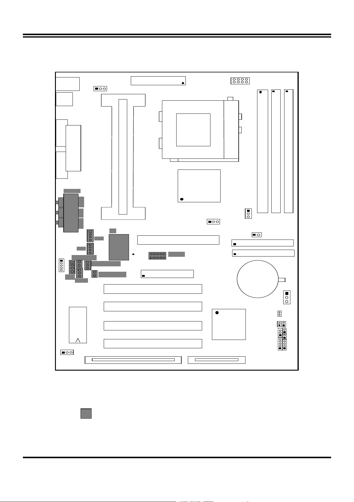
2-2 Mainboard Diagram
J3
DI N
MINI -
USB
J1
CPUFAN
J4
ATX POWER CONN.
SLOT-1
U10
U18
DIMM1
CP U
COM 2
PARALLEL PORT
LINE- OUT
AGC
LI N E- I
MIC
SPKIN 1
J
S PD IF IN 1
SPDIFOUT
COM 2 COM1
J2
GAM E
IR1
JP1
SLOT-1
U11
IA Apoll o Pr o
U7
IDE2
CMI8738B
P1
IDE1
FDD
PCI1
ZI F SOCKET 370
JP11
IDE2
BATT.
DI M M1
DIMM2
DI M M3
BT1
+
PCI 1
PCI2
U16
PCI3
BI OS
PCI4
SL1
VIA 82C596B
PS-ON
SMI
TBSW
JP14
HDLED
RST TBLE
KEYLOCK
SPEAKER
JP1
Figure 2-2
Option for motherboard that embedded Audio chip
4
Page 7
2-3 Quick Reference for Jumpers, Connectors & Expansion Socket
Jumpers
Jumper Name Description Page
JP11,JP12 CPU Bus Frequency Selection Refer to page 6 p. 6
U18 CPU Ratio Selector Refer to page 6 p. 6
JP14 CMOS RAM Clear 1-2 Normal ,2-3 Clear CMOS p. 7
Connectors
Connector Name Description Page
PL1 ATX Power Connector 20-Pin Block p.9
MINI-DIN PS/2 Keyboard/PS/2 Mouse 6-Pin Female p.9
USB USB Port Connector 5-Pin Connector
PRINT Parallel Port Connector 26-Pin Female p.9
COM1, COM2 Serial Port COMA , COMB 9-Pin Connector p.10
FDD Floppy Driver Connector 34-Pin Block p.10
IDE1 Primary IDE Connector 40-Pin Block p.10
IDE2 Secondary IDE Connector 40-Pin Block p.11
HDLED IDE activity LED 2-Pin Connector p.11
SMI SMI Suspend Switch 2-Pin Connector p.11
JP13 Front Panel Connector 16-Pin Block
IR1 Infrared Module Connector 10-Pin Block p.12
CPUFAN, SYSFAN FAN Connector Extra fanning system connectors p.12
PS-ON ATX power button/soft power button 2-Pin Connector p.12
WOL Wake On LAN 3-pin Block P.13
p.11
p.9
Jumpers & Connectors (Option for motherboard that embedded Audio chip)
Item number Name Description Page
JP4 On-Board Sound Enable/Disable 1-2 : Disabled , 2-3 : Enabled p.13
JP1 AUX IN 4-pin Block p.13
JP2 CD-Audio 4-pin Block p.13
JP3 CD-Audio 4-pin Block p.13
AGC Line IN/Line Out/MIC /Game Connector 15-pin Connector + 3 phone jack p.13
SPKIN 1 PC Speaker In 2-pin Block p.14
SPDIFIN 1 SPDIF (Sony/Philips Digital Interface) IN 3-pin Block p.14
SPDIFOUT SPDIF (Sony/Philips Digital Interface) OUT 2-pin Block p.14
JP7 For Optional Optical Kit Connector 10-pin Connector p.14
Expansion Sockets
Socket/Slot Name Description
DIMM1,DIMM2, DIMM3 DIMM Module Socket 168-Pins DIMM SDRAM Module Expansion Socket
Slot1 CPU Slot Pentium II/III CPU Slot
Zip Socket370 CPU Socket Celeron PPGA CPU Socket
AGP SLOT AGP SLOT AGP Expansion Slot
PCI1, PCI2,PCI3 ,PCI4 PCI Slot 32-bit PCI Local Bus Expansion slots
SL1 ISA Slot 16-bit ISA Bus Expansion slot
5
Page 8
g
2-4 Installation Steps
Before using your computer, you must follow the steps as follows:
1. Set Jumpers on the Mainboard
2. Install the CPU
3. Install DRAM Modules
4. Install Expansion card
5. Connect Cables, Wires, and Power Supply
2-5 Jumper Settings
1. CPU Bus Frequency Selection :
CPU External Frequency:JP12, JP11
COM2
JP12
1
3
JP11
•
Users also can setting the CPU Bus frequency in the “CPU Host/PCI clock” in
CPU JP12 JP11 BIOS Setting
66MHz 2-3 ON Default
100MHz 1-2 ON Default
133MHz* 1-2 OFF Default
150MHz* 1-2 OFF 150MHz
∗
Your Memory must meet the requirement to run on 133MHz or 150MHz
condition. In order to run 150MHz, Please set jumper at 133MHz condition and
then chan
JP12, JP11
e the setting to 150MHz from the BIOS.
CHIPSET FEATURES SETUP. (Please refer to page 18)
2. CPU Ratio Selector:U18
Ratio 1 2 3 4 Ratio 1 2 3 4
2.0x ON ON ON ON 5.5x OFF OFF OFF ON
2.5x OFF ON ON ON 6.0x ON ON ON OFF
3.0x ON OFF ON ON 6.5x OFF ON ON OFF
3.5x OFF OFF ON ON 7.0x ON OFF ON OFF
4.0x ON ON OFF ON 7.5x OFF OFF ON OFF
4.5x OFF ON OFF ON 8.0x ON ON OFF OFF
5.0x ON OFF OFF ON
Table for the Pentium III and Celeron Socket 370 CPU
Celeron Pentium III Pentium III
Speed Bus Ratio Speed Bus Ratio Speed Bus Ratio
300/66 66MHz 4.5x 500E/100 100MHz 5.0x 733/133 133MHz 5.5x
333/66 66MHz 5.0x 533EB/133 133MHz 4.0x 750/100 100MHz 7.5x
366/66 66MHz 5.5x 550E/100 100MHz 5.5x 800/100 100MHz 8.0x
400/66 66MHz 6.0x 600E/100 100MHz 6.0x 800EB/133 133MHz 6.0x
466/66 66MHz 7.0x 600EB/133 133MHz 4.5x 850/100 100MHz 8.5x
500/66 66MHz 7.5x 650/100 100MHz 6.5x 866/133 133MHz 6.5x
533/66 66MHz 8.0x 667/133 133MHz 5.0x 933/133 133MHz 7.0x
533A/66 66MHz 8.0x 700/100 100MHz 7.0x 1.0GHz/133 133MHz 7.5x
566/66 66MHz 8.5x
600/66 66MHz 9.0x
633/66 66MHz 9.5x
667/66 66MHz 10.0x
700/66 66MHz 10.5x
733/66 66MHz 11.0x
766/66 66MHz 11.5x
∗ Because the Ratio are fixed by CPU Manufacture, users don’t need
to setting ratio any more, this table just for reference use.
6
Page 9
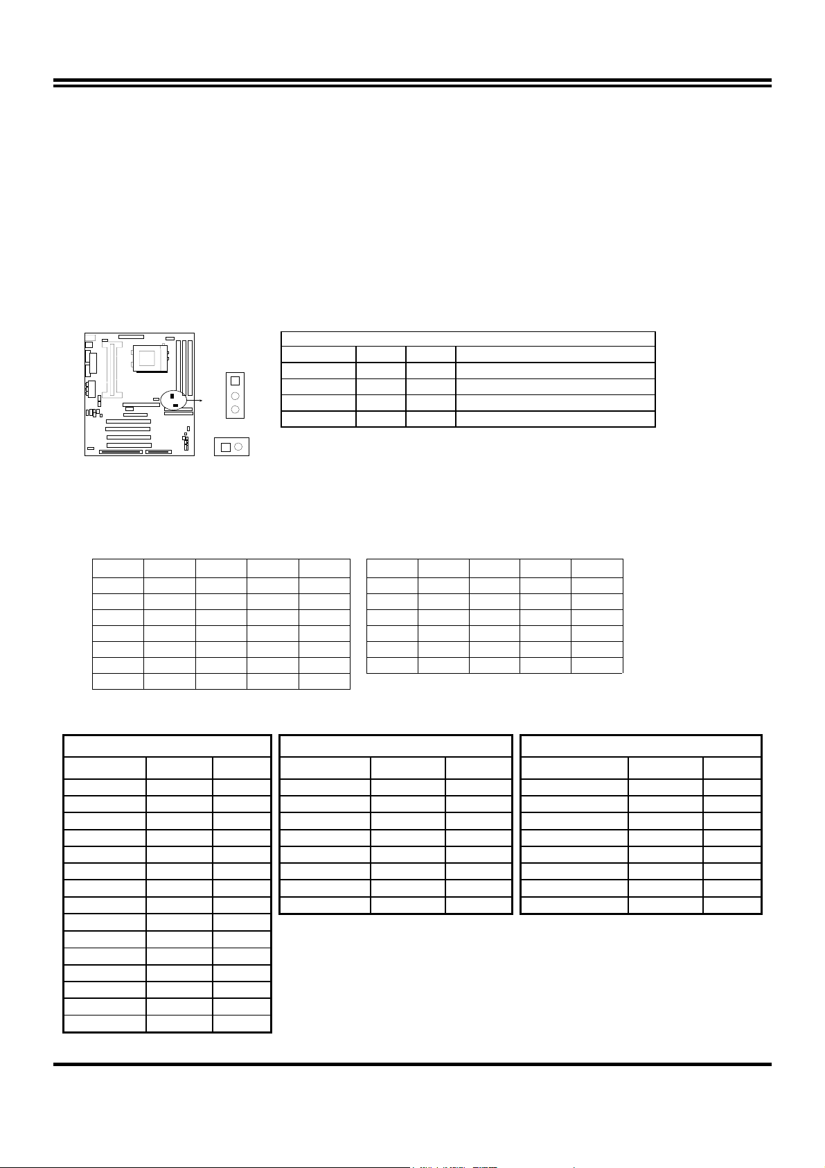
2. CMOS RAM Clear: JP14 (Yellow color selector)
WARNING: Make sure your computer is POWER OFF when you CLEAR CMOS.
Connect a jumper Cap over this jumper for a few seconds, will clears information stored in the
CMOS RAM Chip that input by user, such as hard disk information and passwords. After
CLEAR CMOS, you must enter the BIOS setup (by holding down <DEL> during power-up) to reenter BIOS information (see BIOS SETUP).
Selections JP14
Normal 1-2 (Default)
Clear CMOS 2-3 (momentarily)
JP14
1
2
3
Clear CMOS
COM2
CMOS RAM (Normal / Clear CMOS Data)
JP14
1
2
3
Normal
2-6 System Memory (DRAM)
This mainboard supports three 168-pins DIMM modules, the Max Memory Size is 1.5GB.
DIMM 1
168-pin DIMM
168-pin DIMM 168-pin DIMM
168-pin DIMM
DIMM 2 DIMM 3 System can be Accept or Not
x x Accept
x Accept
168-pin DIMM 168-pin DIMM
Accept
2-7 Central Processing Unit (CPU)
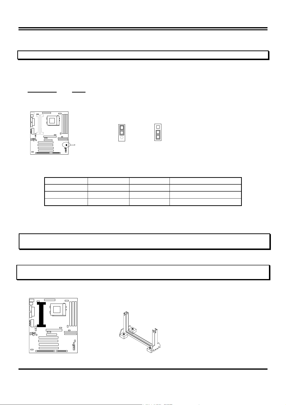
2-7-1 The mainboard provides a Slot-1 for Pentium II/III processor. The CPU on board must
have a fan or heat sink attached to prevent overheating.
WARNING: Without a fan or heat sink, the CPU will overheat and cause damage to both the CPU
and the mainboard.
To install a CPU, first turn off your system and remove its cover. Locate the Slot- 1 and place
RETENTION MODULE as following:
IMPORTANT: You must set jumper JP11,JP12 for “Bus Frequency Selection” on page6 depending
on the CPU that you install.
1. Attach heat sink to the CPU.
2. Place Part A on Slot-1 and gently screw four corners on top of the main- board.
COM2
PART A
7
Page 10
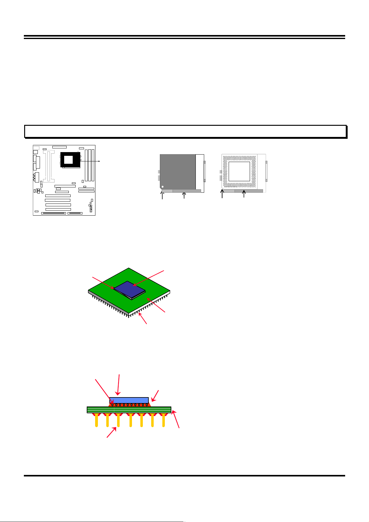
2-7-2 The mainboard also provides a 370-pin ZIF Socket 370. The CPU on mainboard must
have a fan attached to prevent overheating.
To install a CPU, first turn off your system and remove its cover. Locate the ZIF Socket and
open it by first pulling the lever sideways away from the socket then upwards to a 90-degree
right angle. Insert the CPU with the white dot as your guide. The white dot should point towards
the end of the level. The CPU has a corner pin for three of the four corners, the CPU will only fit
in the one orientation as shown as follow. With the added weight of the CPU fan, no force is
required to insert the CPU. Once completely inserted, hold down on the fan and close the
Socket’s lever.
IMPORTANT: You can setting the CPU ratio and Host Frequency in the BIOS setup on page 18
COM2
White Dot
CPU
Socket 370
Lever
CPU ZIF Socket 370
Blank
Lock
Socket 370
2-7-3 Intel® Pentium® III Processor (256K) in the FC-PGA form factor: Mechanical Features
The FC-PGA package has the processor’s silicon die directly mounted to a pinned interposer substrate.
The pin grid array is partially populated and there may be surface mount components in the unpopulated
central area of the pin field.
Fillet Epoxy
Flip Chip Die
Substrate
(Not to scale)
Intel® Pentium® III Processor in the FC-PGA form factor: Mechanical Features
Pins
C4 Solder bumps
Surface mounted pins
Flip-Chip Si Core
Fillet Epoxy
Multi-layer substrate
(Not to scale)
8
Page 11
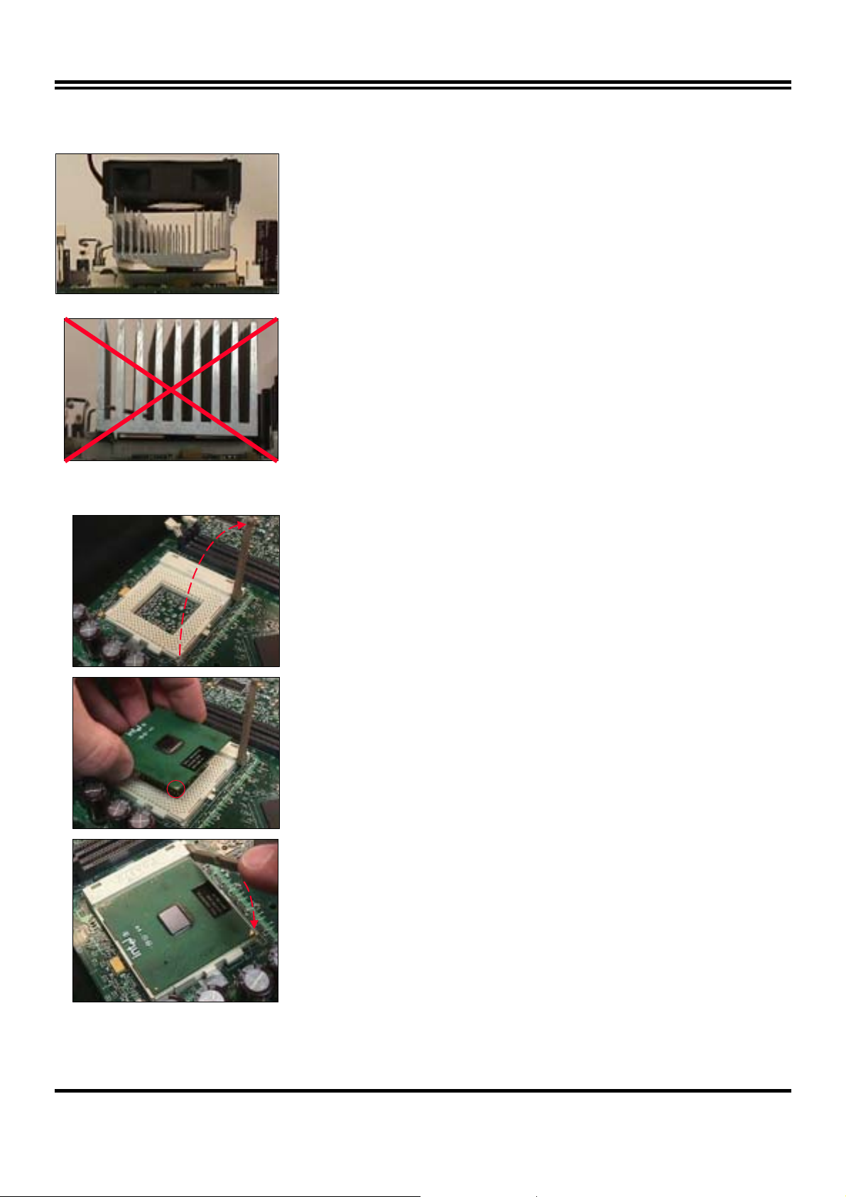
Reference Design: Heatsink
FC-PGA with the reference
FC-PGA with a PPGA heatsink
CPU Insertion
z Intel’s reference design thermal solution is an
active heatsink; an extruded aluminum heatsink
base and a fan attached to the top on the fin
array.
• Heatsinks for the PPGA will not work with the
FC-PGA. A pedestal is required on the
underside of the heatsink to clear the socket
z Recommended thermal interface
material: Chomerics* XTS454.
Step 1
Open the socket by raising the actuation lever.
Step 2
Insert the processor.
Ensure proper pin 1 orientation by aligning the FC-PGA
corner marking with the socket corner closest to the
actuation arm tip. The pin field is keyed to prevent misoriented insertion.
Don’t force processor into socket. If it does not go in easily,
check for mis-orientation and debris.
Make sure the processor is fully inserted into the socket
on all sides.
Step 3
Close the socket by lowering and locking the actuation lever.
9
Page 12
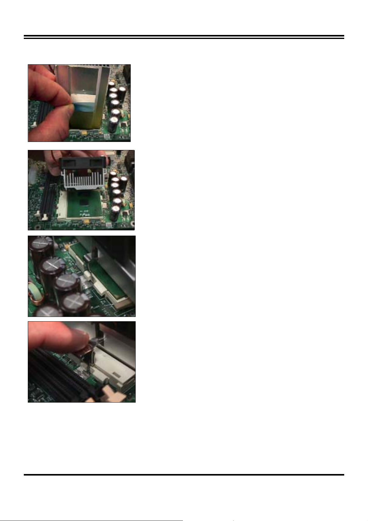
Heatsink Attachment
Step 1
Remove the protective liner from the thermal interface
material on the underside of the heatsink.
This liner is not normally present on the Intel reference
active heatsink.
Step 2
Orient the heatsink with the keyed edge of
heatsink along the cam box side of the
processor.
The clip should be oriented so that the thumb tab will
engage on the cam box side of the socket.
Step 3
Seat the heatsink onto the processor and
engage the clip opposite from the cam box onto
its socket tab first.
CAUTION: Do not slide the heatsink once it is
attached to the processor as the thermal interface
material will tear. Instead lift the heatsink off and
reseat it back down onto the processor if required for
proper alignment.
Step 4
Engage the thumb tab side of the clip onto the
cam box socket tab second.
Connect the fan cable to the appropriate header on the
motherboard.
10
Page 13
2-8 Expansion Cards
You must read the documentation come with expansion card for any hardware or software
settings that may be required to setup your specific card.
Installation Procedure:
1. Read the documentation from your expansion card.
2. Set any necessary jumpers on your expansion card.
3. Remove your computer’s cover.
4. Remove the bracket on the slot you intend to use.
5. Carefully align the card’s connectors and press firmly.
6. Secure the card on the slot with the screw you remove in step 4.
7. Replace the computer’s cover.
8. Setup the BIOS if necessary.
9. Install the necessary software drivers for your expansion card.
Assigning IRQs for Expansion Cards
Some expansion cards may require an IRQ to operate. Generally an IRQ must be exclusively
assigned to only one device. In an standard design there are 16 IRQs available but most of
them are occupied by the system and leaves 6 free for expansion cards.
With most recent device, the BIOS automatically assign an IRQ number to PCI expansion cards.
Please make sure there are no any of two devices use same IRQs, otherwise your computer
may experience some problems when those two devices are in use at the same time.
Assigning DMA Channels for Expansion Cards
Some devices may also need to use a DMA (Direct Memory Access) channel. DMA
assignments for this mainboard are handled the same way as the IRQ assignment process
described above. You can select a DMA channel in the PCI and PnP configuration section of the
BIOS Setup utility.
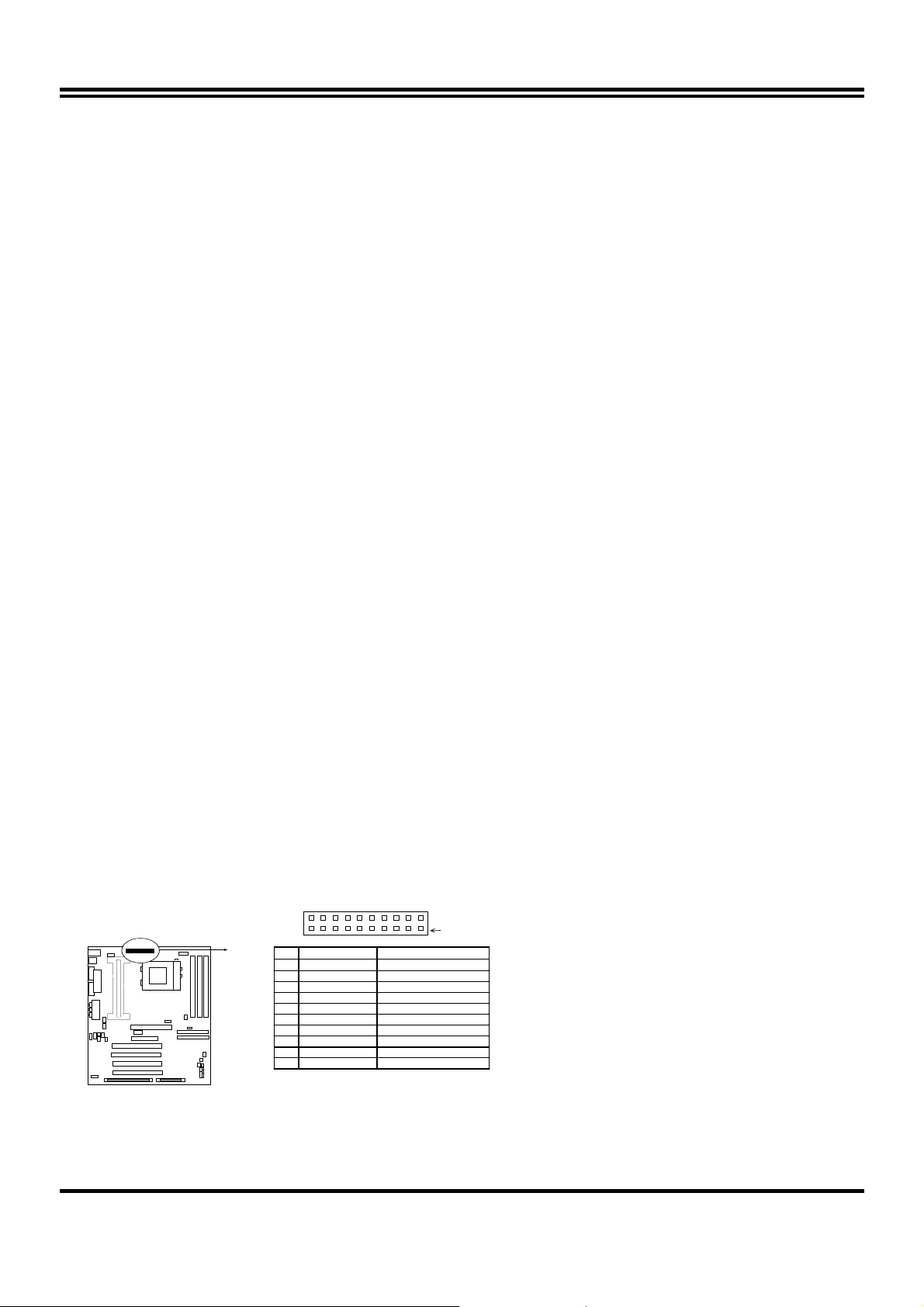
2-9 External Connectors
1. Power Connector: ATX Power Connector (20-pin block): PL1
ATX Power Supply connector. This is a new defined 20-pins connector that usually comes
with ATX case. The ATX Power Supply allows to use soft power on momentary switch that
connect from the front panel switch to 2-pins Power On jumper pole on the mainboard.
When the power switch on the back of the ATX power supply turned on, the full power will
not come into the system board until the front panel switch is momentarily pressed. Press
this switch again will turn off the power to the system board.
PIN 1
PIN ROW2 ROW1
1 3.3V 3.3V
2 -12V 3.3V
3 GND GND
4 Soft Power On 5V
5 GND GND
6 GND 5V
7 GND GND
8 -5V Pow er OK
9 +5V +5VSB (for Soft Logic)
10 +5 V +12V
ATX Power Connector
COM2
11
Page 14
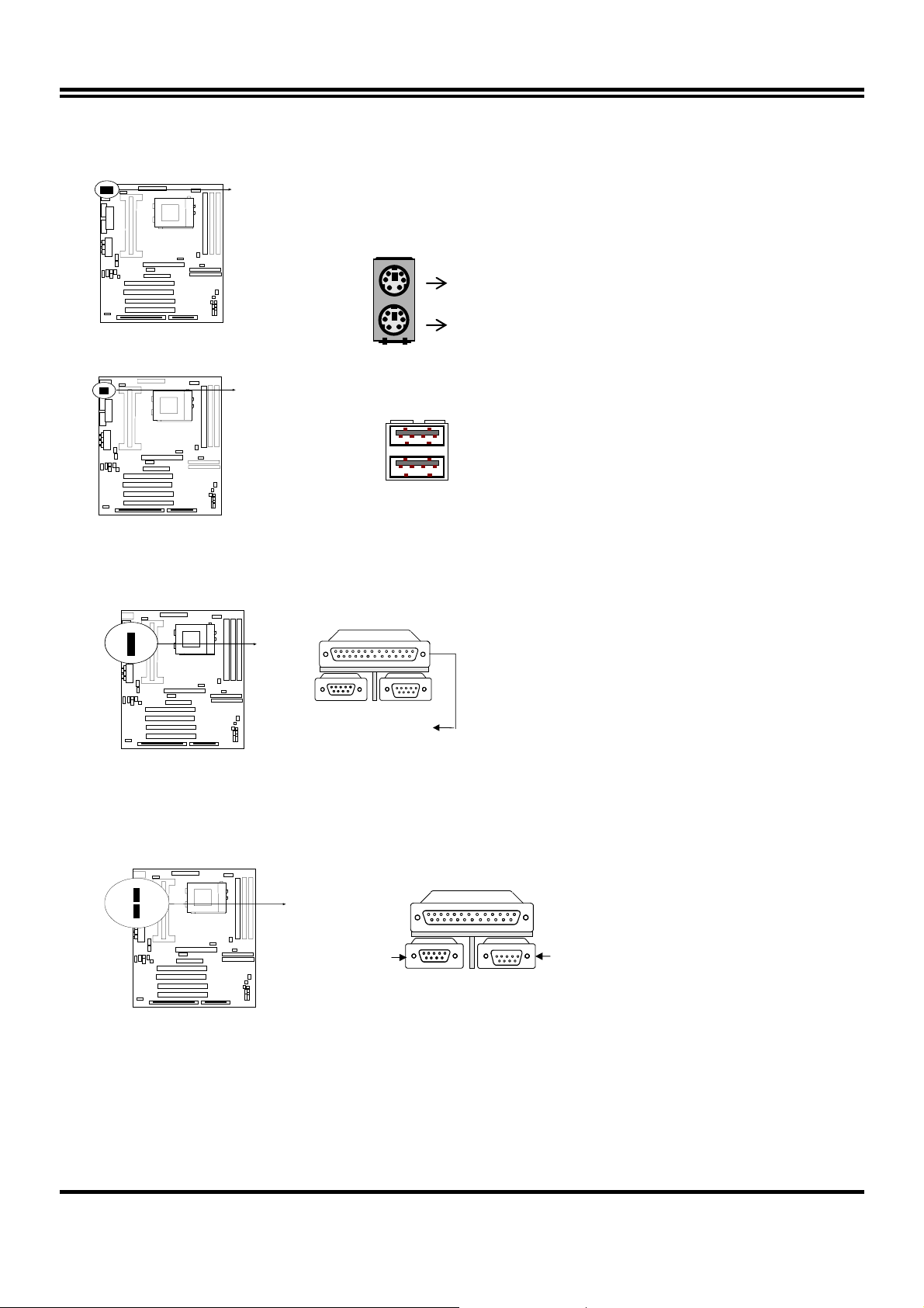
2. PS/2 Mouse & PS/2 Keyboard Connector: MINI-DIN
The connectors for PS/2 keyboard and PS/2 Mouse.
COM2
PS/2 Keyboard
3. USB Port connector: USB
The connectors are 4-pins connector that connect USB devices to the system board.
COM2
USB
USB Port Connector
4. Parallel Port Connector (25-pin female): PRINT
Parallel Port connector is a 25-pin D-Subminiature Receptacle connector. The On-board
Parallel Port can be disabled through the BIOS SETUP. Please refer to Chapter 3
“INTEGRATED PERIPHERALS SETUP” section for more detail information.
COM2
Parallel Port Connector
5. Serial Port COMA, COMB: COM1, COM2
COMA is the 9-pin D-Subminiature mail connector. The On-board serial port can be disabled
through BIOS SETUP. Please refer to Chapter 3 “INTEGRATED PERIPHERALS
SETUP“ section for more detail information.
COM2
COM1
Serial port COMA,COMB Connector
COM2
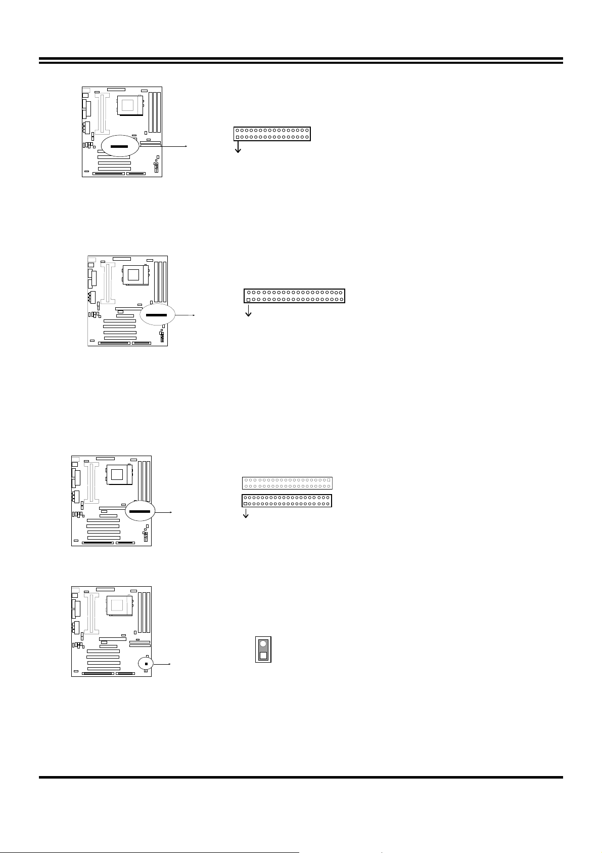
6. Floppy drive Connector (34-pin block): FDD
This connector supports the provided floppy drive ribbon cable. After connecting the single plug
end to mainboard, connect the two plugs at other end to the floppy drives.
12
Page 15
COM2
Pin 1
Floppy drive Connector
7. Primary IDE Connector (40-pin block): IDE1
This connector supports the provided IDE hard disk ribbon cable. After connecting the single
plug end to mainboard, connect the two plugs at other end to your hard disk(s). If you install
two hard disks, you must configure the second drive to Slave mode by setting its jumpers
accordingly. Please refer to the documentation of your hard disk for the jumper settings.
COM2
Pin 1
Secondary IDE Connector
8. Secondary IDE Connector (40-pin block): IDE2
This connector connects to the next set of Master and Slave hard disks. Follow the same
procedure described for the primary IDE connector. You may also configure two hard disks
to be both Masters using one ribbon cable on the primary IDE connector and another ribbon
cable on the secondary IDE connector.
COM2
Pin 1
Secondary IDE Connector
9. IDE activity LED: HDLED
This connector connects to the hard disk activity indicator light on the case.
COM2
HDLED
IDE (Hard Drive) LED
10. SMI Switch : SMI
If your case has Suspend switch , you may connect the cable to this connector in order to
have Suspend mode control from your case.
13
Page 16

VCC
COM2
SMI
SMI Switch
11. Turbo LED switch: TBLED
The mainboard‘s turbo function is always on. The turbo LED will remain constantly lit while
the system power is on. You may wish to connect the Power LED from the system case to
this lead. See the figure below.
12. Reset switch lead: RST
This 2-pin connector connects to the case-mounted reset switch for rebooting your computer
without having to turn off your power switch. This is a preferred method of rebooting in order
to prolong the life of the system‘s power supply. See the figure below.
13. Keyboard lock switch lead: KEYLOCK
This 5-pin connector connects to the case-mounted key switch for locking the keyboard for
security purposes. See the figure below.
14. Speaker connector: SPEAKER
This 4-pins connector connects to the case-mounted speaker. See the figure below.
GND
GND
NC
GND
VCC
Turbo LED
Reset SW
Speaker
Turbo SW
GND
COM2
Power LED
Lock
Keyboard
NC
GND
GND
System Case Connections
15. IR infrared module connector: IR1
This connector supports the optional wireless transmitting and receiving infrared module.
This module mounts to small opening on system cases that support this feature you must
also configure the setting through BIOS setup. Use the four pins as shown on the Back View
and connect a ribbon cable from the module to the mainboard according to the pin definitions.
COM2
IR1
SIR
IR Infrared Module Connector
14
Page 17

16. FAN connector: CPUFAN , SYSFAN
CPUFAN
FAN Connector
COM2
17. Power-On button connector: PS-ON
COM2
GND
18. Wake On Lan connector: WOL
COM2
Power-On button connector
SYSFAN
Push Button
WOL
4
2
※
Wake On LAN Function worked only when power supply support 5VSB more than 750mA
5VSB GND WON
current.
Jumpers & Connectors (Option for motherboard that emedded Audio chip)
19. On Board Audio chip Enabled / Disabled connector: JP4
COM2
1
3
2-3 closed: Enabled
JP4
1-2 closed: Disabled
1
3
20. Auxiliary Input connector: JP1
COM2
JP1
15
Page 18

21. CD Audio in connector : JP2,JP3
JP2 and JP3 are the connectors for CD-Audio Input signal, Please connect it to CD-ROM
CD-Audio output connector
COM2
JP2 :CD-Adio/Panasonic
JP
JP3 :CD-Audio/Sony
22. Audio and Game Connector : AGC
This Connector are 3 phone Jack for LINE-OUT,LINE-IN,MIC and a 15-pin
D-Subminiature Receptacle Connector for joystick/MIDI Device.
Line-out : audio output to speaker
Line-in : audio input to sound chip (Please plug here for second pair speakers as output
channels when use 4 speakers)
MIC : Microphone Connector
Game/MIDI : for joystick or MIDI Device
Game / MIDI PORT
COM2
LINE-OUT MICLINE-IN
Audio and Gam e Connector
23. PC Speaker signal Input connector: SPKIN 1
COM2
SPKIN 1
16
Page 19

7
24. SPDIF (Sony / Philips Digital Interface) Input / Output Connectors: SPDIFIN 1 /
SPDIFOUT
COM2
SPDIFIN
GND
SPDIFIN 1
+5V
SPDIFOUT
SPDIFOUT
GND
25. Optical kit connector: JP7
This connector is for user that has Optical kit(optional) to provide other set of SPDIF
INPUT and SPDIF OUTPUT function.
COM2
JP
2
1
Optical kit Connector
10
9
17
Page 20

Chapter 3
AWARD BIOS SETUP
This mainboard has previously set to its best stable status. If you are not an experienced user,
please do not change the default setting. When you are encounter any problem, please choice
“LOAD STANDARD DEFAULTS” to restore best setting.
Award’s ROM BIOS provides a built-in Setup program which allows user modify the basic system
configuration and hardware parameters. The modified data will be stored in a battery-backed
CMOS RAM so data will be retained even when the power is turned off. In general, the
information saved in the CMOS RAM stay unchanged unless here is configuration change in the
system, such as hard drive replacement or new equipment is installed.
It is possible that CMOS had a battery failure which cause data lose in CMOS_RAM. If so, re-enter
system configuration parameters become necessary.
To enter Setup Program
Power on the computer and press <Del> key immediately will bring you into BIOS CMOS
SETUP UTILITY.
ROM PCI/ISA BIOS (2A6LGJ1F)
CMOS SETUP UTILITY
STANDARD CMOS SETUP
AWARD SOFTWARE, INC.
INTEGRATED PERIPHERALS
BIOS FEATURES SETUP
CHIPSET FEATURES SETUP
POWER MANAGEMENT SETUP
PNP/PCI CONFIGURATION
LOAD OPTIMAL DEFAULTS
LOAD STANDARD DEFAULTS
Esc : QUIT ↑↓→← : Select Item
F10 : Save & Exit Setup (Shift) F2 : Change Color
Time, Date, Hard Disk Type…
SUPERVISOR PASSWORD
USER PASSWORD
SAVE & EXIT SETUP
EXIT WITHOUT SAVING
Figure 3-1
The menu displays all the major selection items and allow user to select any one of shown item.
The selection is made by moving cursor (press any direction key) to the item and press <Enter>
key. An on_line help message is displayed at the bottom of the screen as cursor is moving to
various items which provides user better understanding of each function. When a selection is
made, the menu of selected item will appear so the user can modify associated configuration
parameters.
18
Page 21

3-1 STANDARD CMOS SETUP
STANDARD CMOS SETUP (Figure 3-2) allows user to configure system setting such as current
date and time, type of hard disk drive installed in the system, floppy drive type, and the type of
display monitor. Memory size is auto-detected by the BIOS and displayed for your reference.
When a field is highlighted (direction keys to move cursor and <Enter> key to select), the entries
in the field will be changed by pressing <PgDn> or <PgUp> keys or user can enter new data
directly from the keyboard.
ROM PCI/ISA BIOS (2A6LGJ1F)
STANDARD CMOS SETUP
AWARD SOFTWARE, INC.
Date (mm:dd:yy) : Wed, Sep, 10 1997
Time (hh:mm:ss) : 10 : 33 : 52
HARD DISKS TYPE SIZE CYLS HEAD PRECOMP LANDZ SECTOR MODE
Primary Master : Auto 0 0 0 0 0 0 Auto
Primary Slave : Auto 0 0 0 0 0 0 Auto
Secondary Master : Auto 0 0 0 0 0 0 Auto
Secondary Slave : Auto 0 0 0 0 0 0 Auto
Drive A : 1.4M , 3.25 in.
Drive B : None
Video : EGA/VGA
Halt On : All Errors
Base Memory : 640K
Extended Memory : 7168K
Other Memory : 384K
Total Memory : 8192K
Esc : Quit ↑↓→← : Select Item Pu/Pd/+/- : Modify
F1 : Help (Shift)F2: Change Color
Figure 3-2
NOTE: If hard disk Primary Master/Slave and Secondary Master/Slave were used Auto, than the
hard disk size and model will be auto-detect on display during POST.
NOTE: The “Halt On:” field is to determine when to halt the system by the BIOS is error occurred
during POST.
19
Page 22

3-2 BIOS FEATURES SETUP
Select the “BIOS FEATURES SETUP” option in the CMOS SETUP UTILITY menu allows user
to change system related parameters in the displayed menu. This menu shows all of the
manufacturer’s default values of this mainboard. Again, user can move the cursor by pressing
direction keys and <PgDn> of <PgUp> keys to modify the parameters. Pressing [F1] key to
display help message of the selected item.
This setup program also provide 2 convenient ways to load the default parameter data from
BIOS [F6] or CMOS [F7] area if shown data is corrupted. This provides the system a capability
to recover from any possible error.
ROM PCI/ISA BIOS (2A6LGJ1F)
BIOS FEATURES SETUP
AWARD SOFTWARE, INC.
Virus Warning : Disabled
CPU Internal Cache : Enabled
External Cache : Enabled
CPU L2 Cache ECC Checking : Enabled
Processor Number Feature : Enabled
Quick Power On Self Test : Enabled
Boot Sequence : A,C,SCSI
Swap Floppy Drive : Disabled
Boot Up Floppy Seek : Enabled
Boot Up NumLock Status : On
IDE HDD Block Mode : Enabled
Gate A20 Option : Fast
Memory Parity/ECC Check : Disabled
Typematic Rate Setting : Disabled
Typematic Rate (Chars/Sec) : 6
Typematic Delay (Msec) : 250
Security Option : Setup
PCI/VGA Palette Snoop : Disabled
Esc: Quit ↑↓→← : Select Item
F1 : Help PU/PD/+/-:Modify
F5 : Old Values (Shift)F2 : Color
OS Select For DRAM > 64MB : Non-OS2
HDD S.M.A.R.T Capability : Disabled
Video BIOS Shadow : Enabled
C8000-CBFFF Shadow : Disabled
CC000-CFFFF Shadow : Disabled
D0000-D3FFF Shadow : Disabled
D4000-D7FFF Shadow : Disabled
D8000-DBFFF Shadow : Disabled
DC000-DFFFF Shadow : Disabled
F6 : Load Optimal Defaults
F7 : Load Standard Defaults
Figure 3-2
NOTE: The Security Option contains “setup” and “system”. The “setup” indicates that the password
setting is for CMOS only while the “system” indicates the password setting is for both CMOS
and system boot up procedure.
• Security Option: This category allows you to limit access to the system and
Setup, or just to Setup. The default value is Setup.
System: The system will not boot and access to Setup will be denied if the correct
password is not entered at the prompt.
Setup: The system will boot, but access to Setup will be denied if the incorrect password is
entered at the prompt.
NOTE: To disable security, select PASSWORD SETTING at Main Menu and then you will be asked
to enter password. Do not type anything and just press <Enter>, it will disable security. Once
the security is disabled, the system will boot and you can enter Setup freely.
20
Page 23

F
3-3 CHIPSET FEATURES SETUP
This section describes features of the VIA Apollo Pro AGPset. If your system contains a different
chipset, this section will bear little resemblance to what you see on your screen.
ADVANCED OPTIONS. The parameters in this screen are for system designers, service
personnel, and technically competent users only. Do not reset these values unless you
understand the consequences of your changes.
ROM PCI/ISA BIOS (2A6LGJ1F)
CHIPSET FEATURES SETUP
AWARD SOFTWARE, INC.
Bank 0/1 DRAM Timing : SDRAM 10ns
Bank 2/3 DRAM Timing : SDRAM 10ns
Bank 4/5 DRAM Timing : SDRAM 10ns
SDRAM Cycle Length : 3
DRAM Clock : Host CLK
Memory Hole : Disabled
Read Around write : Disabled
Concurrent PCI/Host : Disabled
System BIOS Cacheable : Enabled
Video RAM Cacheable : Enabled
AGP Aperture Size : 64M
AGP-2X Mode : Enabled
OnChip USB : Enabled
USB Keyboard Support : Disabled
Esc: Quit ↑↓→←: Select Item
F1 : Help PU/PD/+/-:Modify
F5 : Old Values (Shift)F2 : Color
Auto Detect DIMM/PCI Clk : Enabled
Spread Spectrum : Disabled
CPU Host/PCI Clock : Default
Current System Temp. : 34°C/93°F
Current CPU Temperature : 44°C/111°F
Current CPUFAN Speed : 0 RPM
Current SYSFAN Speed : 0 RPM
Core : 2.80V +3.3V : 3.3V
+5V : 5.10V +12V : 12 V
-12V : 12 V
Shutdown Temperature : 75°C/167
F6 : Load Optimal Defaults
F7 : Load Standard Defaults
°
Figure 3-3
• In this item you can choose the CPU HOST/PCI Clock. The setting are:
Default ,66/33,75/37,83/41,100/33,103/34, 112/37,124/41, 105/35,110/36,115/38,
120/40,133/33,140/35,150/37.
When the setting is :”default” the CPU HOST Clock will depend on the setting of JP12 and
JP11.
If JP12,JP11 are set to 66MHz only have the choice of 66/33, 75/37, 83/41 on screen.
If the JP12,JP11 are setting at 100MHz, then you can have 100/33,103/34,112/37,124/41,
105/35,110/36,115/38,120/40.
If JP12,JP11 are setting at 133MHz, the you have the choice: 133/33,140/35,150/37.
*Please turn off system power if the screen does not have any display after change of the
setting. Then press and hold down “ INS ” key, and turn on system power again (release
“ INS ” key till the screen has display) to reset correct frequency of CPU HOST clock.
• DRAM Clock: In this item you have the choice : Host CLK , HCLK+33M, HCLK –33M. We
recommend the Max. DRAM clock ≤ 133MHz otherwise the system will not stable.
• Vcore , +3.3V,+5V,+12V,-12V, are show the status of system voltages.
3-4 POWER MANAGEMENT SETUP
21
Page 24

The Power Management Setup allows you to configure you system to most effectively save
energy while operating in a manner consistent with your own style of computer use.
ROM PCI/ISA BIOS (2A6LGJ1F)
POWER MANAGEMENT SETUP
AWARD SOFTWARE, INC.
ACPI function : Enabled
Power Management : User Define
PM Control by APM : Yes
Video Off After : Suspend
Video Off Method : V/H SYNC+Blank
MODEM Use IRQ : 3
Soft-off by PWRBTN : Instant-off
HDD Power Down : Disabled
Doze Mode : Disabled
Suspend Mode : Disabled
** PM Events **
VGA : OFF
LPT & COM : LPT/COM
HDD & FDD : ON
DMA/master : OFF
Modem Ring Resume : Disabled
RTC Alarm Resume : Disabled
Esc: Quit ↑↓→←: Select Item
F1 : Help Pu/Pd/+/-: Modify
F5 : Old Values (Shift)F2 : Color
Primary INTR : ON
IRQ3 (COM 2) : Primary
IRQ4 (COM 1) : Primary
IRQ5 (LPT 1) : Primary
IRQ6 (Floppy Disk) : Primary
IRQ7 (LPT 1) : Primary
IRQ8 (RTC Alarm) : Disabled
IRQ9 (IRQ2 Redir) : Secondary
IRQ10 (Reserved) : Secondary
IRQ11 (Reserved) : Secondary
IRQ12 (PS/2 Mouse) : Primary
IRQ13 (Coprocessor) : Primary
IRQ14 (Hard Disk) : Primary
IRQ15 (Reserved) : Disabled
F6 : Load Optimal Defaults
F7 : Load Standard Defaults
Figure 3-4
• Power Management: This category allows you to select the type (or degree) of power
saving and is directly related to the following modes:
Doze Mode , Standby Mode ,Suspend Mode , HDD Power Down
There are four selections for Power Management, three of which have fixed mode settings.
Disable (default) No power management. Disables all four modes
Min. Power Saving Minimum power management. Doze Mode = 1 hr. Standby Mode
= 1 hr., Suspend Mode = 1 hr., and HDD Power Down = 15 min.
Max. Power Saving Maximum power management -- ONLY AVAILABLE FOR SL
CPU’S. Doze Mode = 1 min., Standby Mode = 1 min., Suspend
Mode = 1 min., and HDD Power Down = 1 min.
User Defined Allows you to set each mode individually. When not disabled,
each of the ranges are from 1 min. to 1 hr. except for HDD Power
Down which ranges from 1 min. to 15 min. and disable.
• PM Control APM: When enabled, an Advanced Power Management device will be
activated to enhance the Max. Power Saving mode and stop the CPU internal clock.
If the Max. Power Saving is not enabled, this will be preset to No.
• Video Off Method: This determines the manner in which the monitor is blanked.
V/H SYNC+Blank
This selection will cause the system to turn off the vertical and
horizontal synchronization ports and write blanks to the video buffer.
Blank Screen
DPMS
This option only writes blanks to the video buffer.
Initial display power management signaling.
• Video Off After: When enabled, this feature allows the VGA adapter to operate in a power
saving mode.
22
Page 25

N/A
Monitor will remain on during power saving modes.
Suspend Monitor blanked when the systems enters the Suspend mode.
Standby Monitor blanked when the system enters Standby mode.
Doze Monitor blanked when the system enters any power saving mode.
• MODEM Use IRQ:
system. Activity of the selected IRQ always awakens the system.
Name the interrupt request (IRQ) line assigned to the modem (if any) on your
The choices: NA, 3, 4, 5, 7, 9, 10, 11
• PM Timer: The following four modes are Green PC power saving functions which are only
user configurable when User Defined Power Management has been selected see above for
available selections.
• Doze Mode: When enabled and after the set time of system inactivity, the CPU clock will
run at slower speed while all other devices still operate at full speed.
• Standby Mode: When enabled and after the set time of system inactivity, the fixed disk
drive and the video would be shut off while all other devices still operate at full speed.
• Suspend Mode: When enabled and after the set time of system inactivity, all devices except
the CPU will be shut off.
• HDD Power Down: When enabled and after the set time of system inactivity, the hard disk
drive will be powered down while all other devices remain active.
• Throttle Duty Cycle: When the system enters Doze mode, the CPU clock runs only part of
the time. You may select the percent of time that the clock runs.
The Choice: 12.5%, 25.0%, 37.5%, 50.0%, 62.5%, 75.0%
• ZZ Active in Suspend: When Enabled, the ZZ signal is active during Suspend mode.
The Choice: Enabled, Disabled.
• VGA Active Monitor: When Enabled, any video activity restarts the global timer for Standby
mode.
The Choice: Enabled, Disabled.
• Soft-Off by PWR-BTTN: When Enabled, turning the system off with the on/off button places
the system in a very low-power-usage state, with only enough circuitry receiving power to
detect power button activity or Resume by Ring activity.
The Choice: Instant-Off, Delay 4 Sec.
• Resume by Ring: An input signal on the serial Ring Indicator (RI) line (in other words, an
incoming call on the modem) awakens the system from a soft off state..
The Choice: Enabled, Disabled.
• IRQ 8 Break Suspend: You can Enable or Disable monitoring of IRQ8 so it does not
awaken the system from Suspend mode.
The Choice: Enabled, Disabled.
Reload Global Timer Events:
When Enabled, an event occurring on each device listed below restarts the global time for
Standby mode.
IRQ[3 -7, 9-15], NMI , Primary IDE 0 , Primary IDE 1, Secondary IDE 0 , Secondary IDE 1
Floppy Disk , Serial Port , Parallel Port
23
Page 26

3-5 PnP/PCI CONFIGURATION SETUP
This section describes configuring the PCI bus system. PCI, or Personal Computer Interconnect,
is a system which allows I/O devices to operate at speeds nearing the speed the CPU itself uses
when communicating with its own special components. This section covers some very technical
items and it is strongly recommended that only experienced users should make any changes to
the default settings.
ROM PCI/ISA BIOS (2A6LGJ1F)
PNP/PCI CONFIGURATION SETUP
AWARD SOFTWARE, INC.
PNP OS Installed : No
Resources Controlled By : Manual
Reset Configuration Data: Disabled
IRQ-3 assigned to : PCI/ISA PnP
IRQ-4 assigned to : PCI/ISA PnP
IRQ-5 assigned to : PCI/ISA PnP
IRQ-7 assigned to : PCI/ISA PnP
IRQ-9 assigned to : PCI/ISA PnP
IRQ-10 assigned to : PCI/ISA PnP
IRQ-11 assigned to : PCI/ISA PnP
IRQ-12 assigned to : PCI/ISA PnP
IRQ-14 assigned to : PCI/ISA PnP
IRQ-15 assigned to : PCI/ISA PnP
DMA-0 assigned to : PCI/ISA PnP
DMA-1 assigned to : PCI/ISA PnP
DMA-3 assigned to : PCI/ISA PnP
DMA-5 assigned to : PCI/ISA PnP
DMA-6 assigned to : PCI/ISA PnP
DMA-7 assigned to : PCI/ISA PnP
CPU to PCI Write Buffer : Enabled
PCI Dynamic Bursting : Enabled
PCI Master 0 WS Write : Enabled
PCI Delay Transaction : Disabled
PCI#2 Access #1 Retry : Disabled
AGP Master 1 WS Write : Enabled
AGP Master 0 WS Read : Disabled
Assign IRQ For USB : Enabled
Assign IRQ For VGA : Enabled
Esc: Quit ↑↓→←: Select Item
F1 : Help Pu/Pd/+/-:Modify
F5 : Old Values (Shift)F2 : Color
F6 : Load Optimal Defaults
F7 : Load Standard Defaults
Figure 3-5
3-6 LOAD OPTIMAL DEFAULTS
The “LOAD OPTIMAL DEFAULTS” function loads the system Optimal default data directly from
ROM and initialize associated hardware properly. This function will be necessary only when the
system CMOS data is corrupted.
ROM PCI/ISA BIOS (2A6LGJ1F)
CMOS SETUP UTILITY
AWARD SOFTWARE, INC.
STANDARD CMOS SETUP
BIOS FEATURES SETUP
CHIPSET FEATURES SETUP
POWER MANAGEMENT
PNP/PCI CONFIGUR
LOAD OPTIMAL DEFAULTS
LOAD STANDARD DEFAULTS
Esc : QUIT ↑↓→← : Select Item
F10 : Save & Exit Setup (Shift) F2 : Change Color
Load OPTIMAL Default (Y/N)? Y
Time, Date, Hard Disk Type…
INTEGRATED PERIPHERALS
SUPERVISOR PASSWORD
USER PASSWORD
TECTION
ORMAT
SAVE & EXIT SETUP
EXIT WITHOUT SAVING
Figure 3-6
24
Page 27

3-7 LOAD STANDARD DEFAULTS
The “LOAD STANDARD DEFAULTS” function loads the system Standard default data directly
from ROM and initialize associated hardware properly. This function will be necessary only
when the system CMOS data is corrupted.
ROM PCI/ISA BIOS (2A6LGJ1F)
CMOS SETUP UTILITY
AWARD SOFTWARE, INC.
STANDARD CMOS SETUP
BIOS FEATURES SETUP
CHIPSET FEATURES SETUP
POWER MANAGEMENT SETUP
PNP/PCI CONFIGUR
LOAD OPTIMAL DEFAUL
LOAD STANDARD DEFAULTS
Esc : QUIT ↑↓→← : Select Item
F10 : Save & Exit Setup (Shift) F2 : Change Color
Load STANDARD Default (Y/N)? Y
INTEGRATED PERIPHERALS
SUPERVISOR PASSWORD
USER PASSWORD
UP
EXIT WITHOUT SAVING
Time, Date, Hard Disk Type…
Figure 3-7
3-8 INTEGRATED PERIPHERALS SETUP
The “INTEGRATED PERIPHERALS SETUP” mainly deals with I/O function. This function will be
necessary only when the system I/O malfunctioned or the system is unable to detects your CDROM or hard disk.
ROM PCI/ISA BIOS (2A6LGJ1F)
INTEGRATED PERIPHERALS
AWARD SOFTWARE, INC.
OnChip IDE Channel 0 : Enabled
OnChip IDE Channel 1 : Enabled
IDE Prefetch Mode : Disabled
IDE HDD Block Mode : Enabled
IDE Primary Master PIO : Auto
IDE Primary Salve PIO : Auto
IDE Secondary Master PIO : Auto
IDE Secondary Slave PIO : Auto
IDE Primary Master UDMA : Auto
IDE Primary Slave UDMA : Auto
IDE Secondary Master UDMA: Auto
IDE Secondary Slave UDMA : Auto
Init Display First : PCI SLOT
Onboard FDC Controller : Enabled
Onboard SERIAL PORT 1 : 3F8/IRQ4
Onboard SERIAL PORT 2 : 2F8/IRQ3
Esc: Quit ↑↓→←: Select Item
F1 : Help Pu/Pd/+/-:Modify
F5 : Old Values (Shift)F2 : Color
UR2 Mode : Normal
Onboard Parallel Port : 378/IRQ7
Parallel Port Mode : SPP
F6 : Load Optimal Defaults
F7 : Load Standard Defaults
Figure 3-8
25
Page 28

3-9 SUPERVISOR/USER PASSWORD
This item lets you configure the system so that a password is required each time the system
boots or an attempt is made to enter the Setup program (Refer to Figure 3-3 for the details).
Supervisor Password allows you to change all CMOS settings but the User Password setting
doesn’t have this function. The way to set up the passwords for both Supervisor and User are
as follow:
1. Choose either Supervisor Password or User Password in the Main Menu and press
<Enter>. The following message appears:
“Enter Password:”
1. The first time you run this option, enter your password up to only 8 characters and press
<Enter>. The screen does not display the entered characters. For no password just press
<Enter>.
2. After you enter the password, the following message appears prompting you to
confirm the password:
“Confirm Password:”
4. Enter exact the same password you just typed again to confirm the password and press
<Enter>.
5. Move the cursor to Save & Exit Setup to save the password.
6. If you need to delete the password you entered before, choose the Supervisor Password and
Press <Enter>. It will delete the password that you bad before.
7. Move the cursor to Save & Exit Setup to save the option you did, otherwise the old password
will still be there when you turn on your machine next time.
3-10 SAVE & EXIT SETUP
The “SAVE & EXIT SETUP” option will bring you back to boot up procedure with all the changes
you just made which are recorded in the CMOS RAM.
3-11 EXIT WITHOUT SAVING
The “EXIT WITHOUT SAVING” option will bring you back to normal boot up procedure without
saving any data into CMOS RAM. All of the old data in the CMOS will not be destroyed.
26
Page 29

Chapter 4
4-1 Mainboard Driver Install in Win9X,WinNT
To install the mainboard driver please run
X:\VIA\Driver\SETUP.EXE.
After execute Setup .EXE the screen will depend on the OS (Operating System) to show the
necessary Driver which you have to install in your system, such like IDE Driver, AGP VXD
Driver, VIA chipset Feature Registry and IRQ Routing Miniport Driver . Follow the procedure
to install the driver.
We recommend to install all the Driver which this utility show in Screen ,because it will
increase the system performance and solve the compatibility problem between system
chipset and other device.
For Example , You have to install this driver before you install AGP VGA driver otherwise it
can’t install your VGA Driver succeed.
27
Page 30

4-2 PC HEALTH MONITOR-III (OPTION FOR MOTHERBOARD THAT
EMBEDDED PC Health) Software for Windows 95/98
Please Run X:\VIA\HEALTH3\SETUP.EXE
NOTES 1. For Windows 95 user:You must run SETUP.EXE twice in order to
complete this installation. The computer will install device
identification at first time when you run SETUP.EXE. When you
finish, you need re-start your computer manually and run
SETUP.EXE once again to install correspond driver.
2. Please follow on screen instruction to complete your installation.
3. Please refer to HELP for Windows 95/98 related questions.
General Description
The PC HEALTH MONITOR-III Software, an application software based on Microsoft Windows 95,
is used to control the PC HEALTH MONITOR CHIP. It can monitor the temperatures, power
supply voltages and fan speeds via PC HEALTH MONITOR CHIP and show the information on
screen periodically. User can use it to specify temperature, voltage and fan speed configurations
used by monitor chip. By the way, the alarm warning events and polling interval could also be set
by this software. If there is an abnormal event happens, it will pop up a window on screen to
inform the user the abnormal situation.
Using the Software
General Function
1. Power Supply Voltage :
VCORE Low Limit/High Limit
3.3V Low Limit/High Limit
+5V Low Limit/High Limit
+12V Low Limit/High Limit
28
Page 31

-12V Low Limit/High Limit
These values are used to specify the threshold values of detecting the abnormal condition of ,
3.3V, +5V, +12V, -12V.
2. FAN Speed
CPUFAN/ SYSFAN
If the fan RPM is lower than this value and “CPUFAN/SYSFAN” is enabled in Monitoring
Config. the PC Speaker will alarm and the monitor software will pop up a window to inform
user.
3. Temperature
System/ CPU Low Limit/ High Limit
There values is used to specify the Temp-Over register/ Tem-under register of PC HEALTH
MONITOR CHIP, If the temperature of the external thermistor is higher than this value and
“System/CPU” is enabled in Monitoring Config. the monitor software will pop up a window to
inform user.
Monitoring Config.
Enabled or Disabled: User can decide which item should be monitored or not by choosing the
item in the configuration page.
Faults Count (1 or 3): User can decide the system to pop up the warning message when there
is 1 fault detected or there are 3 consecutive faults detected.
Beep: In addition to pop up warning message user can choose to activate Beep
tone if there is error detected. Beep tone will until the error is treated.
4-3 Sound Driver & Audio Rack Installation( Option for Motherboard
That Embedded PC Health Chip ) :
29
Page 32

Special Features for CMI8738 audio chip
PCI Plug and Play (PnP) bus interface, 32 bit PCI bus master.
Full duplex playback and recording, built-in 16 bits CODEC.
HRTF 3D positional audio, supports both Direct Sound 3D® & A3D® interfaces, supports
earphones, two and four channel speakers mode.
Support Windows 3.1 / 95 / 98 and Windows NT 4.0.
Built-in 32 OHM Earphone buffer and 3D surround.
MPU-401 Game/Midi port and legacy audio SB16 support.
Downloadable Wave Table Synthesizer, supports Direct Music®.
• Digital Audio (SPDIF IN/OUT)
Up to 24 bit stereo 44KHz sampling rate voice playback/recording.
Full duplex playback and recording, 120dB audio quality measured.
Auto detectable SPDIF/IN signal level from 0.5V to 5V.
• Stereo Mixer and FM Music Synthesizer
Stereo analog mixing from CD-Audio, Line-in
Stereo digital mixing from Voice, FM/Wave-table, Digital CD-Audio
Mono mixing from MIC and software adjustable volume
OPL3 FM synthesizer (4 operators)
Up to 15 melody sounds and 5 rhythm sounds (20 voices)
• Game and Midi Interface
Fully compatible with MPU-401 Midi UART and Sound Blaster Midi
mode/ Standard IBM PC joystick/game port (dual channels)
DOS Installation
Before beginning the installation, please make sure that your hard disk has sufficient space(min.
4MB). Insert the Driver CD into the CD-ROM Drive.
1. Change directory to PCI audio DOS drivers folder (ex. X:\CMI8738\DOSDRV) at DOS prompt,
and type:
INSTALL [Enter]
2. Type DOS utilities path which you want to install.
3. Program will expand the file to the path which you've specified.
4. Install program will add initial drivers into AUTOEXEC.BAT file.
Win95/98 Installation
We recommend that you install Microsoft Windows before you install this PCI sound card,
and you not install any other sound card device drivers in your current system.
1. Turn on the computer , and enter the Microsoft Windows 95/98
2. Before install sound card driver please double-click “My Computer” icon, “Control Panel” icon ,
“System” icon, and choose “Device Manager” item.
3. Check “Other Device” item ,if there have “PCI Multimedia Audio Device”, please remove it
first ,and Restart System again.
4. You will see a windows prompt like this:
“New Hardware Found PCI Multimedia Audio Device Windows has found new hardware and
is installing the software for it” , then the dialog box shown Click “Next” button to go on.
5. Click “Other Locations” button to specify drivers path:
“ X:\CMI8738\Win9X\DRV”
6. Select “OK” to finish install.
30
Page 33

7. Now, system is installing device drivers automatically. After a while, the system will finish the
installation includes the following device drivers.
CMI8738/C3DX PCI Audio Device
CMI8738/C3DX PCI Audio Joystick Device
CMI8738/C3DX PCI Audio Legacy Device
DOS mode MPU-401 Emulator
8. Install Application Software : Click “start” key
9. Select “Run”
10. Key in the drive and path for Windows application installation program, for example,
in Win95 “X:\CMI8738\Win9X\APP\Win95\SETUP.EXE”
in Win98 “X:\CMI8738\Win9X\APP\Win98\SETUP.EXE”
11. Click “OK” to start the installation procedure, and follow the on-screen instructions to finish
the installation. When all the application softwares have been installed, please shut down
Windows 95/98 system, and reboot your system.
Win95/98 Un-Installation
If you install Win95/98 and a sound card at the same time, you might experience some
technical difficulties(the device might not function properly). It is suggested that you proceed
with the un-install procedure:
1. Click "start" button.
2. Select "run" item.
3. Find UINSTDRV.EXE in driver disk under Win95/98 drivers folder.
4. Run it.
5. Follow the on-screen instructions to re-install the hardware.
If you want to completely remove the drivers, you can also run the un-install procedure as
described previously. Remove the sound card from the slot, and then reboot the system.
Windows NT 4.0 Installation
We recommend that you install Windows NT 4.0 before you install this PCI audio card, and you
not install any other sound card device drivers in your current system.
1. Click “Start” button, move the highlight bar to “Setting” item, and select the “Control Panel”.
2. Double-click “Multimedia” icon.
3. Select “Devices” page, and press “Add” button.
4. Select “Unlisted or Updated Driver” item in “List of Drivers”.
5. Specify the drive and the path where NT drivers are in (such as X:\CMI8738\NT40\DRV).
6. Select “C-Media CM8738” item and press “OK” button.
7. Select proper I/O value.
8. Press “OK” button.
9. Restart the system when being asked.
10. Now, you have already installed the PCI Audio Adapter under Microsoft Windows NT 4.0
successfully. if you want to install the Windows applications, continue the following steps:
11. Click “start” key.
12. Select “Run” item.
13. Key in drive and path for Windows NT application installation program, for example,
31
Page 34

“X:\CMI8738\NT40\APP\SETUP.EXE”
14. Click “OK” to start the installation procedure, and follow the on-screen instructions to finish
the installation. When all of application softwares have been installed, shut down the
Windows NT system, and then reboot your system.
Windows Appc. (The Audio Rack)
Introduction
By means of a user-friendly interface(as easy as operating your home stereo system), this PCI
audio rack provides you with the control over your PC’s audio functions, including the advantage
of four speakers mode enable/ disable, and perfect digital sound ( SPDIF ) input / output control.
This Audio Rack consists of several major components:
Control Center: Controls the display of the PCI Audio Rack’s components.
MIDI Player: Plays MIDI music files, and allows you to create your personal song playlists, and
play the song files.
Wave Player: Records and plays digital audio (wave) files. Allows you to create wave file
playlists, and playback the wave files.
CD Player: Plays standard audio CDs. Allows you to create your favorite song playlists.
System Mixer: Controls the volume level of your audio inputs and outputs.
Showing or Hiding Audio Rack Components
To remove or add a component from the display, click on the component's button on the Control
Center’s Button Bar or toggle it off.
MIDI Player, Wave Player, and CD Player
CD Player (above, similar to Wave Player and MIDI Player)
Sel (or Trk) field: If you have multiple selections in your playlist, this shows the number of the
current selection or CD track.
Current File or Track: The name of the current MIDI file, wave audio file, or CD track.
Total Length field: displays the total length of files or tracks in minutes and seconds.
32
Page 35

Current Time field: displays the current time of files or tracks in minutes and seconds when
playback or recording.
Please refer to the help screen for more detail button function descriptions. (click on help “ ”
button on the player)
System Mixer
System Mixer allows you to control all the audio output and input levels.
System Mixer displays the volume controls which your audio drivers make available. The names
for these controls may vary.
Mixer panel while the four speakers mode is enabled.
Mixer panel while the four speakers mode is disabled.
Volume Control: Clicking on this button shows and allows you to use the output level controls.
Recording Control: Clicking on this button shows and allows you use the input level controls.
Input and Output Level Sliders and Buttons: For each input or output signal type, the control
slider controls the loudness whereas the horizontal slider controls the balance between the two
speakers. The mute button temporarily stops input or output without changing slider positions.
Control types and names might vary. The common types are listed below:
• Vol: The master control for all outputs. The strength of an output signal is determined by both
the Vol slider and the slider for the individual output. To affect all outputs, move the Vol slider.
To change the output of an individual output type, move its slider.
• Line-in/Rear: Controls the audio hardware's Line In or Line Out levels. Line levels might be for
an externally attached cassette player, for instance, while the four speakers mode is enabled,
this control becomes the Rear speaker volume control.
• Mic: Controls the microphone input level.
• Wave: Controls wave (voice) playback or the recording levels.
• FM: Controls the FM music playback or the recording level.
• Aux-in: Controls the Aux-in music play or the recording level.
• PC-SPK: Controls the external PC speaker input level.
• CD: Controls the CD drive output level, for CD drives configured to play their audio output
through the PC’s audio hardware.
• 4SPK: Turn on or turn off the Rear speakers effect.
• Surround: Turn on or turn off the 3D surround sound effect.
• SPDIF-in: Turn on or turn off the SPDIF digital signal input.
• Advanced: Check the SPDIF status, HRTF 3D sound CPU Utilization, turn on th Microphone
Booster.
33
Page 36

Mute Buttons: Toggle between muting and enabling the signal. A button with a lit LED is
enabled, and when it is not lit, it means it is mute. Several output signals can usually be enabled
at once.
MP3 Player : MP3 player can play both wave files and MP3 files.
MP3 player while the loop function enables.
The settings’ window while one of the SPDIF functions is enable.
The 4 Speakers System
This Audio Adapter provides 2 wave channels(front/rear), known as the 4 speakers system.
When games or application programs via DirectSound® 3D or A3D® interface locate the sound
sources to the listener's back, the two rear speakers will work to enhance the rear audio
positional effect, so as to complement the insufficiency of using only two front speakers to
emulate the audio effect. The following is the hardware installation and the software setups:
1. The speaker installation.
Connect the front pair speakers to the Line-out jack of the audio adapter, and then connect rear
pair speakers to Line-in/Rear jack of the audio adapter. The original Line-in can be moved to
Aux-in.
2. The positions of the speakers
Put your speakers the way the following picture suggests, so as to avail yourself to the best
34
Page 37

audio result.
3. The mixer setup
There is a 4 speakers option in the volume control of the mixer, and when you enable this option,
it means the rear speakers are connected to Line-in/Rear jack. When Line-in/Rear jack is
connected to other external Line-in sources, please DO NOT enable this option in order to avoid
hardware conflicts. Regarding rear speaker option, you can turn on or turn off the output of the
back speakers, and adjust the volume, to have the rear/front speakers have the same volume.
3. The demo
Execute the "Helicopter" demo within the C3D HRTF Positional Audio Demos of this audio
adapter. When the helicopter flies behind you, the rear speakers will work.
Optical Kid for SPDIF/OUT (Option for motherboard that embedded PC Health chip)
The Optical Kid includes:
z Optical Module
z Optical Cable
z Software DVD driver
OPTICAL MODULE
DIP-SWITCH
J1:SPDIF-IN
OPTICAL OUT
OPTICAL IN
An example of optical kit with MD connection.
35
Page 38

The application program setup(please install CMI8738 application program first)
When the connection is done, please go to the Start menu and select PCI Audio
Applications\Audio Environment Setting
36
Page 39

When all the procedures have been completed, there will be an infrared signal coming from the
SPDIF/OUT of the optical fiber of the sound card.
Please note that signal beam may cause severe damage to the eyes. For your safety,
please point the output end to a piece of white paper to check if thebeam is in function.
Please connect the output signal to the MD input, then play the music via the MP3 player.
37
Page 40

Please note that in playback, if there is no gap longer than three seconds between each track, the
MD can not recognize the tracks and will record all of them into one. It is recommended that you
set the gap time to 3~5 seconds to meet all type of MD requirements.
38
Page 41

About Recording 24bit Audio Setting
39
Page 42

24-bit audio can only be applied to SPDIF IN/OUT mode; it does not apply to other modes
such as the four channels or the analog. No sound will be heard while in playback, yet it
can be recorded.
The un-selected area will be gray out.
The un-selected area will be gray out.
40
Page 43

The un-selected area will be gray out.
You can double-click this circuit icon to have the following setting box. By means of this
setting box, you can also complete the above-mentioned setting procedures.
41
Page 44

SPDIF/IN for motherboard that embedded Audio chip
An example of Portable CD Player(Output) to Main Board (Optical Input)Setup
When the connection is done, please go to the Start menu and select PCI Audio
Applications\Audio Environment Setting
42
Page 45

Loopback(bypass)mode setup
CD ROM(Digital Output) to SPDIF/IN Setup
43
Page 46

When the connection is done, please go to the Start menu and select PCI Audio
Applications\Audio Environment Setting
44
Page 47

Please follow these setting procedures.
Now you can insert the CD into the CD ROM drive, then activate C-MEDIA CD player and
push the ”play” button to do the recording job.
Please note that you have to set the MD in the simultaneous-recording mode.
45
 Loading...