


i
Chapter 1
1-1 Preface ........................................................................................... 1
1-2 Key Feature ...................................................................................
1
Chapter 2
Installation .................................................................................. 3
2-1 Unpacking ........................................................................................ 3
2-2 Mainboard Layout ............................................................................ 4
2-3 Installation Steps ............................................................................. 6
2-3-1 Jumper Settings ................................................................... 6
2-3-2 System Memory (DRAM) ..................................................... 8
2-4 Central processing Unit (CPU) ........................................................ 8
2-5 Expansion Cards ............................................................................. 9
2-6 External Connectors ........................................................................ 10
Chapter 3
AWARD BIOS SETUP ................................................................. 16
3-1 STANDARD CMOS SETUP ............................................................... 17
3-2 BIOS FEATURES SETUP .................................................................. 17
3-3 CHIPSET FEATURES SETUP ........................................................... 21
3-4 POWER MANAGEMENT SETUP ...................................................... 22
3-4-1 The Description of the Power Management......................... 22
3-4-2 Description of the Green Functions ..................................... 23
3-5 PNP/PCI CONFIGURATION SETUP ................................................. 24
3-6 LOAD BIOS DEFAULTS .................................................................... 25
3-7 LOAD SETUP DEFAULTS ................................................................. 25
3-8 INTEGRATED PERIPHERALS SETUP ............................................. 26
3-9 SUPERVISOR/USER PASSWORD ................................................... 28
3-10 IDE HDD AUTO DETECTION .......................................................... 28
3-11 SAVE & EXIT SETUP ....................................................................... 30
3-12 EXIT WITHOUT SAVING ................................................................. 30
3-13 I/O & MEMORY MAP ....................................................................... 30
3-14 TIME & DMA CHANNELS MAP ....................................................... 32
3-15 INTERRUPT MAP ............................................................................ 32
3-16 RTC & CMOS RAM MAP ................................................................. 32
3-17 BIOS REFERENCE-POST CODES ................................................. 33
TABLE OF CONTENT

1
Chapter 1
1-1 Preface
Welcome to use the J-791A/J-791A/L mainboard. This mainboard supports Pentium II
processor PC/AT compatible system with AGP slot,ISA bus and PCI local bus. Also this board
including some special designs, like ACPI/APM power management & powerful performance ,
We think you will enjoying your personal computer because of your right choice.
1-2 Key Feature
The J-791A/J-791A/L is designed for the PC user who wants a great many features in a small
package. This motherboard:
• SDRAM Clock selectable (66MHz/100MHz),in 100MHz Bus Frequeney,let users more
choice when use SDRAM.
• AGP: Accelerated Graphics Port for 533MB/sec data transfer rate and 66MHz Bus clock
to improve graphic functions.
• Easy Installation: Is equipped with BIOS supports auto detection of hard drives and plug
and play to make setup of hard drives and expansion cards virtually automatic.
• Chipset: VIA APOLLO PRO VT82C691/VT82C596 PCI/AGPset with I/O subsystems.
• Multi-Speed Support: Supports Intel Pentium II processor from 233MHz to 450MHz on
Slot-1.
• DRAM Memory Support: Support 3x168-pin DIMMs of 16MB, 32MB, 64MB, 128MB,
256MB from a memory size between 16MB to 768M.
• AGP, ISA and PCI Expansion Slots: Provides an AGP slot, two 16-bit ISA slots, and four
32-bit PCI slots.
• Super Multi-I/O: Provides two high-Speed UART compatible serial ports and one parallel
port with EPP and ECP capabilities. Two floppy drives of either 5.25” or 3.5” (1.44MB or
2.88MB) are also supported without an external card.
• PCI Bus Master IDE Controller and ULTRA DMA 33: On-board PCI Bus Master IDE
controller with two connectors that supports four IDE devices in two channels, provides
faster data transfer rates, and supports Enhanced IDE devices such as Tape Backup, CDROM drives and LS-120. This controller also supports PIO Modes 3 and 4 and Bus Master
IDE DMA 33Mbyte/Sec.
•
ACPI supporting for OS Directed Power Management.
Ring-ln Wake up: When Ring-In the system can wake up from SMI Mode.
Ring-ln Power On: When Ring-In the system can power on automatic by this function.
Wake On LAN: Workstation can power on by Server in Network.
RTC Power On: Enabled RTC Power On function, you can setting RTC alarm to power on the
system at the time length you setting.
Power Button: Press the button will place the system power on/off.

2
CPU fan auto-stopping when in suspend mode.
Support Software Power Off function.
• Power Support: Efficient PWM switching power instead of traditional Linear Voltage
Regulator to prevent power component from being burned-out.
• PC 97 ready
• PS/2 Mouse: This motherboard support PS/2 mouse set.
• USB Port Connector: This motherboard supports two USB port connectors for USB
devices.
• ATX Form Factor: Dimensions 30.5cmx18cm.
• Optional IrDA: This motherboard supports an optional infrared port module for wireless
interface, with independent 3rd UART (32-byte FIFO).
• Fans: Support two Extra fan connectors to evacuate the heat from CPU, and the heat
within the computer case.
• PC HEALTH MONITOR: (Only in J-791A/L)
To frack PC system temperature system Vottage,and Fan speed. When system
temperature is over warning temperature by HEALTH Monitor Utility will have alarm to warn
users.

3
Chapter 2
Hardware Installation
2-1 Unpacking
This mainboard package should contain the following:
• The J-791A/J-791A/L mainboard
• USER’S MANUAL for mainboard
• Cable set for IDE x1, Floppy x1
• CD for Drivers PACK
The mainboard contains sensitive electronic components which can be easily damaged by
electron-static, so the mainboard should be left in its original packing until it is installed.
Unpacking and installation should be done on a grounded anti-static mat.
The operator should be wearing an anti static wristband, grounded at the same point as the
anti-static mat.
Inspect the mainboard carton for obvious damage. Shipping and handling may cause damage
to your board. Be sure there are no shipping and handling damages on the board before
proceeding.
After opening the mainboard carton, extract the system board and place it only on a grounded
anti-static surface component side up. Again inspect the board for damage.
Press down on all of the socket IC’s to make sure that they are properly inserted. Do this only
on with the board placed on a firm flat surface.
Warning: Do not apply power to the board if it has been damaged.
You are now ready to install your mainboard. The mounting hole pattern on the mainboard
matches the IBM-AT system board.
It is assumed that the chassis is designed for a standard IBM XT/AT main board mounting.
Place the chassis on the anti-static mat and remove the cover.
Take the plastic clips, Nylon stand-off and screws for mounting the system board, and keep
them separate.
4
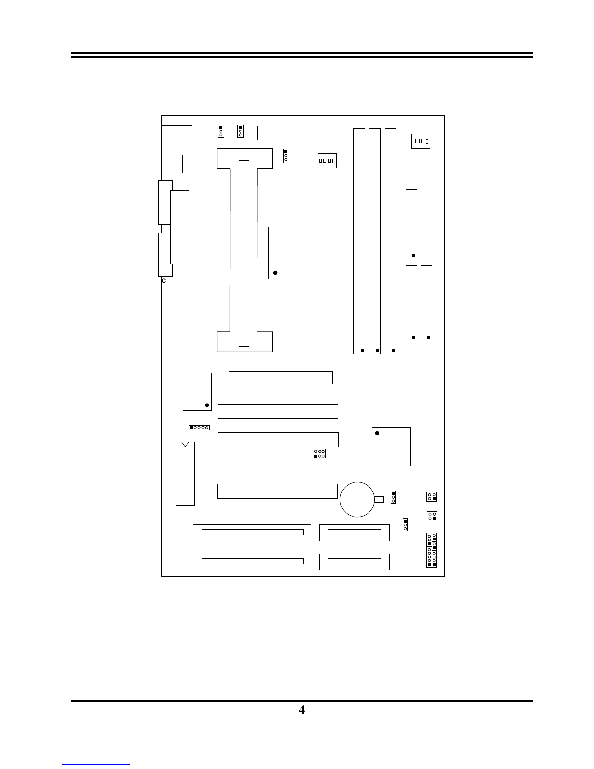
2-2 Mainboard Layout
FLOPPY
FDD1
2
1
34
33
KB/MS
W83977TF
USB
ATX POWER CONN.
CN1
VT82C691
U2
ON
4321
AGP1
AGP SLOT
DIM1
DIM3
DIM2
SLOT1
SLOT-1
POWER-LED
SPEAK
RSET
TURBO-LED
TUBRO-SW
4
3
1
2
J9
PS/2
MOUSE
&
K/B
COM1
COM2
COM2
COM PORT COM PORT
LPT1
PRINT
2
1
IDE2
40
39
2
1
IDE1
40
39
PCI 1
PCI 2
ISA2
JP2
1
VT82C596
+
JBAT1
1
3
BOIS
1 5
U4
ON
4321
DIMM3
DIMM2
DIMM1
USB1
SB-LINK1
1
PWB-BIN
4
3
1
2
WON1
1
3
Figure 2-1

5
Jumpers
1) U4 p. 7 DIP Switch for CPU Ratio Selection
2)
JBAT1 p. 7 CMOS RAM (Normal/Clear CMOS Data)
(Yellow
color selector)
3) U2 p. 7 DIP Switch for CPU BUS Frequency Selection
Connectors
1) CN1 p. 10 ATX Power connector (20-pin Block)
2) KB/MS p. 11 PS/2 Keyboard & PS/2 Mouse connector (6-pin Female)
3) LPT1 p. 11 Parallel Port connector (25-pin Block)
4) COM1, COM2
p. 11 Serial Port COMA & COMB (10-pin Block)
5) FDD1 p. 12 Floppy Driver connector (34-pin Block)
6) IDE1 p. 12 Primary IDE connector (40-pin Block)
7) IDE2 p. 12 Secondary IDE connector (40-pin Block)
8) SMI_SW(J9 2&4) p. 13 SMI Suspend Switch lead (2-pin)
9) HDLED
(J9 1&3)
p. 13 IDE activity LED connector (2-pin)
10) TBLED p. 13 Turbo LED switch (2-pin)
11) RESET p. 13 Reset Switch lead (2-pin)
12) KEYLOCK/Power LEDp. 13 Keyboard Lock Switch Power/LED (5-pin)
13) SPEAKER p. 13 Speaker connector (4-pin)
14) JIR1 p. 13 Infrared Module connector (5-pin)
15) USB1
p. 14 USB Port connector
16) CPUFAN p. 14 CPU Fan connector
17) FAN1 p. 14 Extra fanning system connectors
18) PWR_BTN
(J5 2&4)
p. 15 Power-On Button connector
19) SB_LINK1 p.15 SBLINK connector
20) WON 1 p.15 Wake On Lan connector
Expansion Slots
1) DIMM Slots p. 8 DRAM Memory Expansion slots
2) Slot-1 p. 8 Slot for Central Processing Unit (CPU)
3) AGP Slot p. 9 AGP Expansion slot
4) ISA 1,2 p. 9 16-bit ISA Bus Expansion slots
5) PCI 1,2,3,4 p. 9 32-bit PCI Bus Expansion slots
6
2-3 Installation Steps
Before using your computer, you must follow the steps as follows:
1. Set Jumpers on the Motherboard
2. Install the CPU
3. Install DRAM Modules
4. Install Expansion card
5. Connect Cables, Wires, and Power Supply
6. Setup the BIOS Software
2-3-1 Jumper Settings
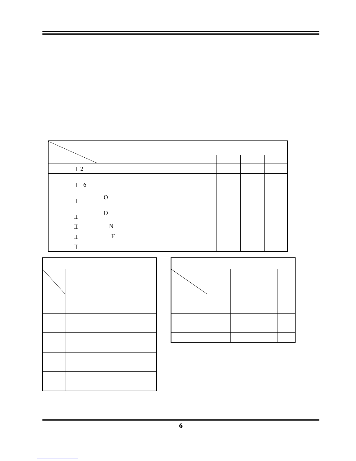
1. DIP Switch for CPU Type Selection:U4,U2
DIP SW
CPU TYPE
U4 U2
#1 #2 #3 #4 #1 #2 #3 #4
Pentium Ⅱ 233
ON OFF OFF ON OFF OFF OFF OFF
Pentium Ⅱ 266
OFF ON ON ON OFF OFF OFF OFF
Pentium
Ⅱ
300
OFF ON OFF ON OFF OFF OFF OFF
Pentium Ⅱ 333
OFF OFF ON ON OFF OFF OFF OFF
Pentium Ⅱ 350
ON OFF OFF ON OFF OFF ON OFF
Pentium Ⅱ 400
OFF ON ON ON OFF OFF ON OFF
Pentium Ⅱ 450
OFF ON OFF ON OFF OFF ON OFF
CPU ratio selector U4
BUS Frequency selector U2
NO
Ratio
#1 #2 #3 #4
NO
#1 #2 #3
#4
2.5X ON ON OFF ON 66.6MHz OFF OFF OFF OFF
3.0X ON OFF ON ON 75MHz OFF ON OFF OFF
3.5X ON OFF OFF ON 100MHz OFF OFF ON OFF
4.0X OFF ON ON ON 103MHz ON OFF ON OFF
4.5X OFF ON OFF ON 112MHz OFF ON ON OFF
5.0X OFF OFF ON ON
5.5X OFF OFF OFF ON
6.0X ON ON ON OFF
6.5X ON ON OFF OFF
7.0X ON OFF ON OFF
Frequency
Celeron 266
Celeron 300
Celeron 333

7
COM2
ON
4321
300MHz
266MHz
ON
4321
233MHz
ON
4321
U4
ON
4321
333MHz
350MHz
ON
4321
400MHz
ON
4321
ON
4321
450MHz
U2
266MHz
300MHz
350MHz
333MHz
400MHz
450MHz
ON
4321
ON
4321
ON
4321
ON
4321
ON
4321
ON
4321
233MHz
ON
4321
2. SDRAM Clock Selector: U2 #4
This selector can choose SDRAM clock Synchronous or Asynchronous to CPU Bus frequency. When
choose Asynchronous can let users have more choice of NON-PC100 SDRAM at over 66 MHz Bus
frequency .
U2 #4 ON SDRAM clock same as AGP clock (66MHz) Asynchronous.
U2 #4 OFF SDRAM clock same as CPU Bus clock (66MHz,75MHz,100MHz,
103MHz,112MHz): Synchronous.
3. CMOS RAM: JBAT1 (Yellow color selector)
WARNING: Make sure your computer is POWER OFF when you are CLEAR CMOS.
Connect a jumper Cap over this jumper for a few seconds, will clears information stored in
the CMOS RAM Chip that input by user, such as hard disk information and passwords.
After CLEAR CMOS, you must enter the BIOS setup (by holding down <DEL> during
power-up) to re-enter BIOS information (see BIOS SETUP).
Selections JBAT1
Normal 1-2 (Default)
Clear CMOS 2-3 (momentarily)
COM2
Normal
JUBA1
1
2
3
CMOS RA M (Norm al / Clear CMOS Data)
Clear CMOS
JUBA1
1
2
3
8
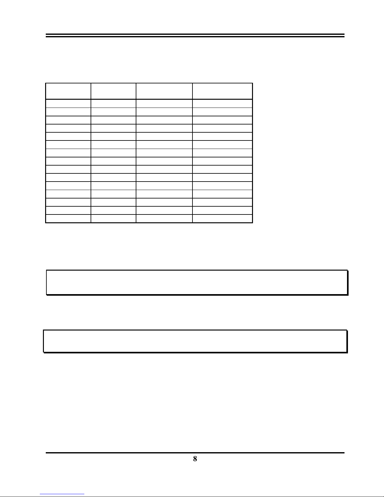
2-3-2 System Memory (DRAM)
This motherboard support tree168-pin DIMM Module, using +3V unbuffer synchronous DRAM
in either EDO or SDRAM with Max. memory size of 768MB.
DIMM1 DIMM2 DIMM3
Total Memory
Combination
16MB
none
none
16MB
16MB
16MB
none
32MB
16MB
16MB
16MB
48MB
32MB
none
none
32MB
32MB
32MB
none
64MB
32MB
32MB
32MB
96MB
64MB
none
none
64MB
64MB
64MB
none
128MB
64MB
64MB
64MB
192MB
128MB
none
none
128MB
128MB
128MB
none
256MB
128MB
128MB
128MB
384MB
256MB
none
none
256MB
256MB
256MB
none
512MB
256MB
256MB
256MB
768MB
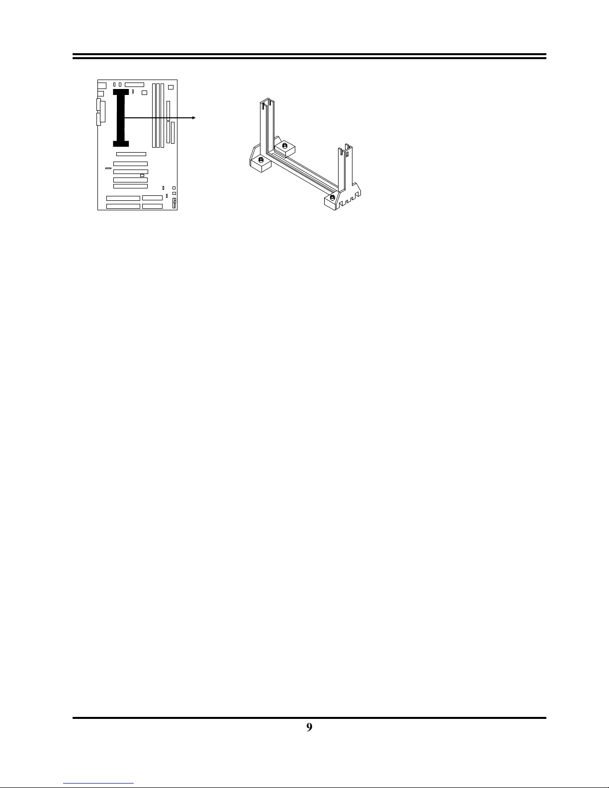
2-4 Central Processing Unit (CPU)
The motherboard provides a Slot-1 for Pentium II processor. The CPU on board must have a
fan or heat sink attached to prevent overheating.
WARNING: Without a fan or heat sink, the CPU will overheat and cause damage to both the CPU
and the motherboard.
To install a CPU, first turn off your system and remove its cover. Locate the Slot- 1 and place
RETENTION MODULE as following:
IMPORTANT: You must setswitch U4,U2 for both “CPU to Bus frequency Ratio” and “Bus
Frequency Selection” on page 7 depending on the CPU that you install.
➀
Attach heat sink to the CPU.
➁ Place Part A on slot-1 and gently screw four corners on top of the mother-board.
9
COM2
PART A
2-5 Expansion Cards
You must read the documentation come with expansion card for any hardware or software
settings that may be required to setup your specific card.
Installation Procedure:
1. Read the documentation from your expansion card.
2. Set any necessary jumpers on your expansion card.
3. Remove your computer’s cover.
4. Remove the bracket on the slot you intend to use.
5. Carefully align the card’s connectors and press firmly.
6. Secure the card on the slot with the screw you remove in step 4.
7. Replace the computer’s cover.
8. Setup the BIOS if necessary.
9. Install the necessary software drivers for your expansion card.
Assigning IRQs for Expansion Cards
Some expansion cards may require an IRQ to operate. Generally an IRQ must be exclusively
assigned to only one device. In an standard design there are 16 IRQs available but most of
them are occupied by the system and leaves 6 free for expansion cards.
Either AGP, ISA or PCI expansion cards may require an IRQs. System IRQs are available to
cards installed in the ISA expansion first, and any remaining IRQs can be used by PCI cards.
Currently, there are two types of ISA cards. An original ISA expansion card design, know as
“Legacy” ISA cards, they request configure the card’s jumpers manually and then install it in
any available slot on the ISA bus, and other know as Plug and Play. You may use Microsoft’s
Diagnostic (MSD.EXE) utility included in the DOS directory to see a map of your used and any
free IRQs. For Windows 95 users, the “Control Panel” icon in “My Computer”, contains a
“System” icon which gives you “Device Manager” tab. Double clicking on a specific device
give you “Resources” tab which shows the Interrupt number and address. Make sure that no
any two of devices use the same IRQs, or your computer will experience problems when those
two devices are in use at the same time.
10
To simplify this process the motherboard has complied with the Plug and Play (PNP)
specification which was developed to allow automatic system configuration whenever a PNPcompliant card is added to the system. For PNP cards, IRQs are assigned automatically from
those available.
If the system has both Legacy and PNP ISA cards installed, IRQs are assigned to PNP cards
from those not used by Legacy cards. The PCI and PNP configuration of the BIOS setup utility
can be used to indicate which IRQs are being used by Legacy cards. For older Legacy cards
that does not work with the BIOS, you can contact your vendor for an ISA Configuration Utility.
An IRQ number is automatically assigned to PCI expansion cards after those used by Legacy
and PNP ISA cards. In the PCI bus design, the BIOS automatically assigns an IRQ to a PCI. To
install a PCI card, you need to set something called the INT (interrupt) assignment. Since all
the PCI slots on this motherboard use an INTA #, be sure that the jumpers on your PCI cards
are set to INT A.
Assigning DMA Channels for ISA Cards
Some ISA cards, both Legacy and PNP may also need to use a DMA (Direct Memory Access)
channel. DMA assignments for this motherboard are handled the same way as the IRQ
assignment process described above. You can select a DMA channel in the PCI and PNP
configuration section of the BIOS Setup utility. In the BIOS setup, you should choose “Yes” for
those IRQ’s and DMA’s you wish to reserve for Legacy cards.
2-6 External Connectors
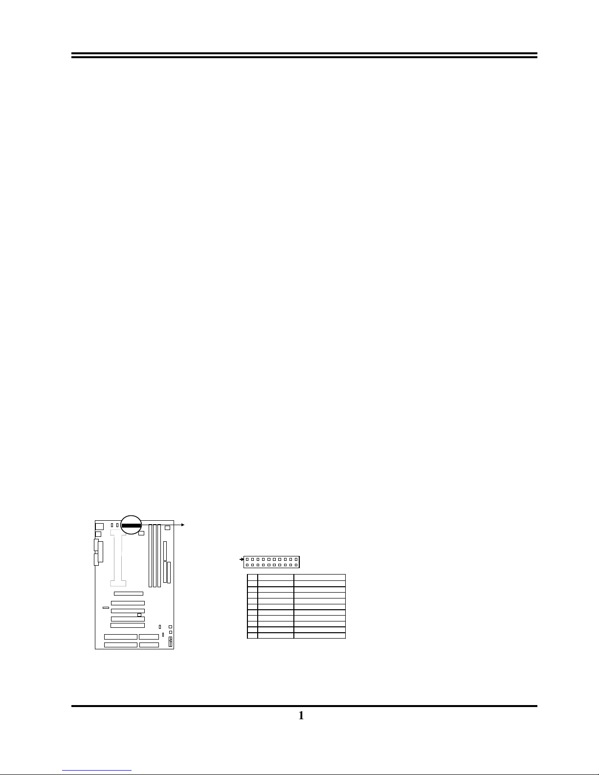
1. ATX Power Connector (20-pin block): CN1
ATX Power Supply connector. This is a new defined 20-pin connector that usually comes
with ATX case. The ATX Power Supply allows to use soft power on momentary switch that
connect from the front panel switch to 2-pins Power On jumper pole on the motherboard.
When the power switch on the back of the ATX power supply turned on, the full power will
not come into the system board until the front panel switch is momentarily pressed. Press
this switch again will turn off the power to the system board.
COM2
PIN
ROW2 ROW1
1 3.3V 3.3V
2 -12V 3.3V
3 GND GND
4 Soft Power On 5V
5 GND GND
6 GND 5V
7 GND GND
8 -5V Power OK
9 +5V +5VSB (for Soft Logic)
10 +5V +12V
ATX Power Connector
Pin 1
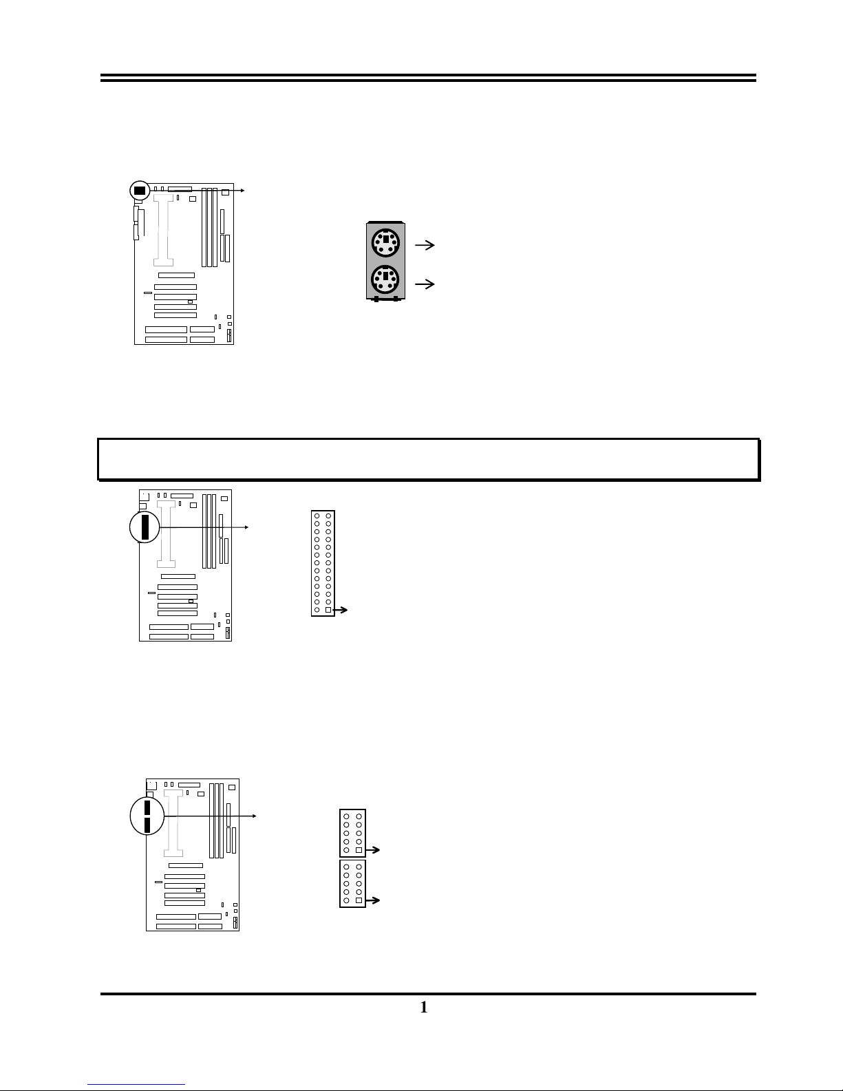
2. PS/2 Mouse & PS/2 Keyboard Connector: KB/MS
11
The PS/2 Keyboard is a 6-pin miniature DIN connector. It is for a standard PS/2 style
keyboard. May also be known as a 101 enhanced keyboard. The PS/2 Mouse connector
is a similar 6-pin, miniature DIN connector.
COM2
3. Parallel Printer Connector (26-pin block): LPT1
Connection for the included parallel port ribbon cable with mounting bracket. Connect the
ribbon cable to this connection and mount the bracket to the case on an open slot. It will
then be available for a parallel printer cable.
NOTE: Serial printers must be connected to the serial port. You can enable the parallel port and choose the
IRQ through BIOS Setup on page 25 “Onboard Parallel Port”.
COM2
Parallel Printer Connector
Pin 1
LPT1
4. Serial port COMA and COMB Connector (Two 10-pin block): COM1, COM2
These connectors support the provided serial port ribbon cables with mounting bracket.
Connect the ribbon cables to these connectors and mount the bracket to the case on an
open slot. The two serial ports on the mounting bracket will then be used for pointing
devices or other serial devices. See page 25 for BIOS configuration of “Onboard Serial
Port”
COM2
COM1
Pin 1
COM2
Serial port COMA and COMB Connector
5. Floppy drive Connector (34-pin block): FDD1
PS/2 Keyboard
PS/2 Mouse
 Loading...