

Page 1

Chapter 1
Features of This Motherboard....................................................1
Chapter 2
Installation....................................................................................3
2-1 Map of the Motherboard...........................................................3
2-2 Installation Steps......................................................................5
2-2-1 Jumper Settings....................................................................5
2-2-2 System Memory (DRAM).......................................................9
2-3 Central processing Unit (CPU)................................................9
2-4 Expansion Cards......................................................................10
2-5 External Connectors................................................................12
Chapter 3
AWARD BIOS SETUP..................................................................18
3-1 STANDARD CMOS SETUP.................................................................19
3-2 BIOS FEATURES SETUP....................................................................20
3-3 CHIPSET FEATURES SETUP.............................................................24
(Only in J-5TXA/L) For M/B with LM75 and LM78 on board...........25
3-4 POWER MANAGEMENT SETUP........................................................27
3-4-1 The Description of the Power Management..........................27
3-4-2 Description of the Green Functions......................................28
3-5 PNP/PCI CONFIGURATION SETUP...................................................29
3-6 LOAD BIOS DEFAULTS......................................................................30
3-7 LOAD SETUP DEFAULTS..................................................................31
3-8 INTEGRATED PERIPHERALS SETUP...............................................31
3-9 SUPERVISOR/USER PASSWORD.....................................................34
3-10 IDE HDD AUTO DETECTION............................................................34
3-11 SAVE & EXIT SETUP........................................................................37
3-12 EXIT WITHOUT SAVING...................................................................37
3-13 I/O & MEMORY MAP.........................................................................37
3-14 TIME & DMA CHANNELS MAP........................................................39
3-15 INTERRUPT MAP..............................................................................39
3-16 RTC & CMOS RAM MAP...................................................................40
3-17 BIOS REFERENCE-POST CODES...................................................41
i
TABLE OF CONTENT
Page 2

ii
Page 3

Chapter 1
Features of This Motherboard
The J-5TXA/ J-5TXA/L is designed for the PC user who wants a great many
features in a small package. This motherboard:
Easy Installation: Is equipped with BIOS supports auto detection of hard
drives and plug and play to make setup of hard drives and expansion cards
virtually automatic.
Intel chipset: Intel’s 430TX PCIset with I/O subsystems.
Multi-Speed Support: Support one of 75~266MHz CPU on a ZIF Socket 7,
such as Intel Pentium processor and Intel Pentium processor with MMX
technology, AMD-K5 /AMD-K6, Cyrix 6x86/Cyrix 6X86MX CPU.
One Jumper: Only one jumper selector for CPU External Clock Frequency
and Bus/Core Ratio selected, it is easy for user to install CPU.
L2 Cache: Provides on board 512KB Pipelined Burst SRAM.
DRAM Memory Support: Supports 4x72-pin SIMMs and 2x168-pin DIMMs
(3.3v)of 4MB, 8MB, 16MB, 32MB, or 64MB to from a memory size between
8MB to 256MB. Support both Fast Page Mode and Extended Data Output
(EDO) SIMMs. The J-5TXA/ J-5TXA/L also supports Synchronous DRAM
module (DIMM).
ISA and PCI Expansion Slots: Provides four 16-bit ISA slots, four 32-bit PCI
slots.
Super Multi-I/O: Provides two high-Speed UART compatible serial ports and
one parallel port with EPP and ECP capabilities. Two floppy drives of either
5.25” or 3.5” (1.44MB or 2.88MB) are also supported without an external card.
PCI Bus Master IDE Controller and ULTRA DMA 33: On-board PCI Bus
Master IDE controller with two connectors that supports four IDE devices in
two channels, provides faster data transfer rates, and supports Enhanced IDE
devices such as Tape Backup, CD-ROM drives and LS-120. This controller
also supports PIO Modes 3 and 4 and Bus Master IDE DMA 33Mbyte/Sec.
Bundle with “TRIONES” ULTRA DMA 33 Driver to improve IDE transfer
rate for up to 33Mbyte/sec.
ACPI supporting for OS Directed Power Management.
Ring-ln Wake up: When Ring-In the system can wake up from SMI Mode.
Ring-ln Power On: When Ring-In the system can power on automatic by this
function.
RTC Power On: Enabled RTC Power On function, you can setting RTC alarm to
power on the system at the time length you setting.
1
Page 4

Power Button: Press the button will place the system power on/off.
CPU fan auto-stopping when in suspend mode.
Support Software Power Off function.
Power Support: Efficient PWM switching power instead of traditional Linear
Voltage Regulator to prevent power component from being burned-out.
PC 97 ready
PS/2 Mouse: This motherboard support PS/2 mouse set.
USB Port Connector: This motherboard supports two USB port connectors
for USB devices.
Baby AT Form Factor: Dimensions 30.5cm x 18.5cm.
Optional IrDA: This motherboard supports an optional infrared port module
for wireless interface, with independent 3rd UART (32-byte FIFO).
Consumer IR: Consumer infrared for remote AV functions (Option).
Fans: Support three Extra fan connectors to evacuate the heat from CPU,
and the heat within the computer case.
With LM78/LM75: (Only in J-5TXA/L)
To track PC CPU temperature, system temperature, system voltage and fan
speed. When CPU current temperature is over CPU warning temperature,
system will slow down automatically to reduce the CPU’s temperature.
2
Page 5
Chapter 2
Installation
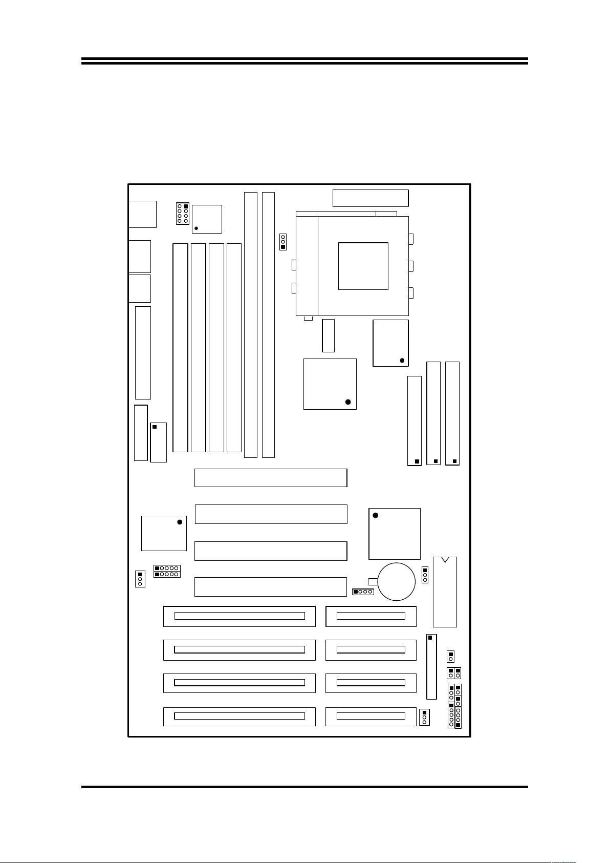
2-1 Map of the Motherboard
W8397 7TF
CPUFAN1
1 2
+
LPT.
KB.
MOUSE
COM1
J1
J5
J2
J3
PCI 1
PCI 2
PCI 4
KEYLOCK
SPEAKER
RESET
TB-LED
TB-SW
SMI
HD-LED
M5
M 6
M4
M3
M2
M1
USB
COM2
ATX POWER CONN.
J13
32KX8
64KX64
PRIMARY IDE
SECONDARY IDE
FDC.
J14
J15
J17
2
1
2
1
2
1
34
33
40
39
40
39
JP6
1
4
371AB
JERP1
1
3
LM78
25
26
1
5
JIR1
CPU
SOCKET 7
JP1
J4
J6
871
2
1
3
BOIS
J16
439TX
1
6
5
10
1
5
JCIR1
FAN1
FAN2
1
Figure 2-1
3
Page 6

Jumpers
1)
JERP1 p. 5 Flash ROM voltage Setting
(Yellow color
selector)
1)
JP1 p. 5 CPU Voltage Selection
(Yellow color selector)
2)
J16 p. 6 One Jumper Selection for CPU Type
(Blue color
selector)
4)
JP6 p. 8 CMOS RAM (Normal/Clear CMOS Data)
(Yellow
color selector)
Connectors
1) J13 p. 12 ATX Power connector (20-pins Block)
2) KB p. 12 PS/2 Keyboard connector (6-pins Female)
3) MOUSE p. 12 PS/2 Mouse connector (6-pins Female)
4) J3 p. 13 Parallel Port connector (25-pins Female)
5) COM1
(J4)
p. 13 Serial Port COMA (9-pins Male)
COM2
(J6)
p. 13 Serial Port COMB (10-pins Block)
6) FDC. (J14) p. 14 Floppy Driver connector (34-pins Block)
7)
PRIMARY IDE(J17)
p. 14 Primary IDE connector (40-pins Block)
8)
SECONDARY IDE(J15)
p. 14 Secondary IDE connector (40-pins Block)
9) SMI p. 15 SMI suspend Switch lead (2-pins)
10) TB-LED p. 15 Turbo LED switch (3-pins)
11) RESET p. 15 Reset Switch lead (2-pins)
12) KEYLOCK p. 15 Keyboard Lock Switch (5-pins)
13) SPEAKER p. 16 Speaker connector (4-pins)
14) HD-LED p. 16 IDE activity LED connector (2-pins)
15) JIR1 p. 16 Infrared Module connector (5-pins)
16) JCIR1 p. 17 Consumer IR Module connector (5-pins)
17) USB (J5)
p. 17 USB Port connector
18)
CPUFAN1, FAN1, FAN2
p. 17 CPU Fan connector, Extra fanning system
connector
19) JP7 p. 17 Power-On Button connector
Expansion Slots
1) SIMM Slots p. 9 DRAM Memory Expansion slots
2) DIMM Slots p. 9 DRAM Memory Expansion slots
3) ZIF Socket 7 p. 10 Socket for Central Processing Unit (CPU)
4) ISA 1,2,3,4 p. 10 16-bit ISA Bus Expansion slots
5) PCI 1,2,3,4 p. 10 32-bit PCI Bus Expansion slots
4
Page 7
2-2 Installation Steps
Before using your computer, you must follow the steps as follows:
1. Set Jumpers on the Motherboard
2. Install the CPU
3. Install DRAM Modules
4. Install Expansion card
5. Connect Cables, Wires, and Power Supply
6. Setup the BIOS Software
2-2-1 Jumper Settings
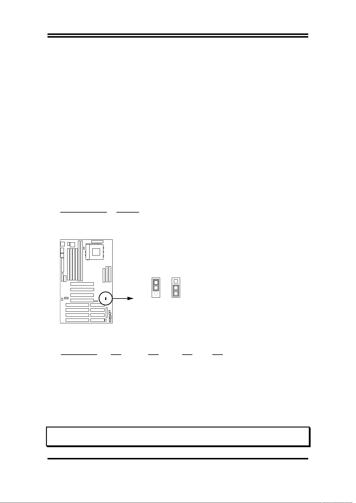
1. Flash ROM Voltage Selection: JERP1 (Yellow color selector)
These jumpers set the voltage supplied to the Flash ROM. It depend on
Flash ROM Brand.
Programming JERP1
+12V 1-2 (Intel, MXIC)
+5V 2-3 (SST, Winbond)
JERP1
JERP1
+12V
+5V
132
1
3
2
Flash ROM Voltage Selection
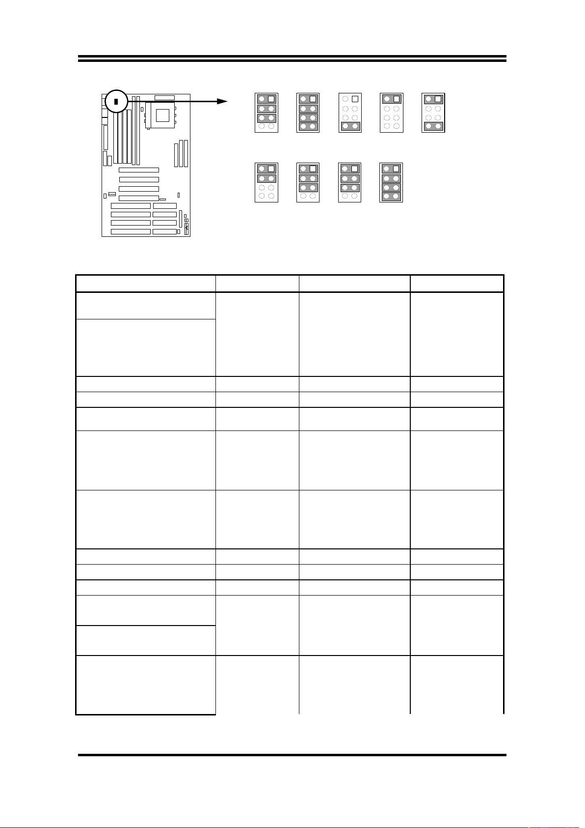
2. CPU Voltage Selection: JP1 (Yellow color selector)
Selections 1-2 3-4 5-6 7-8
2.04V short short short open
2.10V short short short short
2.14V open open open short
2.84V short open open open
2.94V short open open short
3.24V short short open open
3.34V short short short open
3.44V short short short open
3.54V short short short short
NOTE: Before install the CPU, Please check the CPU Voltage from your supplier.
5
Page 8
3.34V
1
2
7
8
JP1
CPU Voltage Selection
2.04V
1
2
7
8
JP1
2.14V
1
2
7
8
JP1
2.84V
1
2
7
8
JP1
2.94V
1
2
7
8
JP1
3.24V
1
2
7
8
JP1
3.44V
1
2
7
8
JP1
3.54V
1
2
7
8
JP1
2.10V
1
2
7
8
JP1
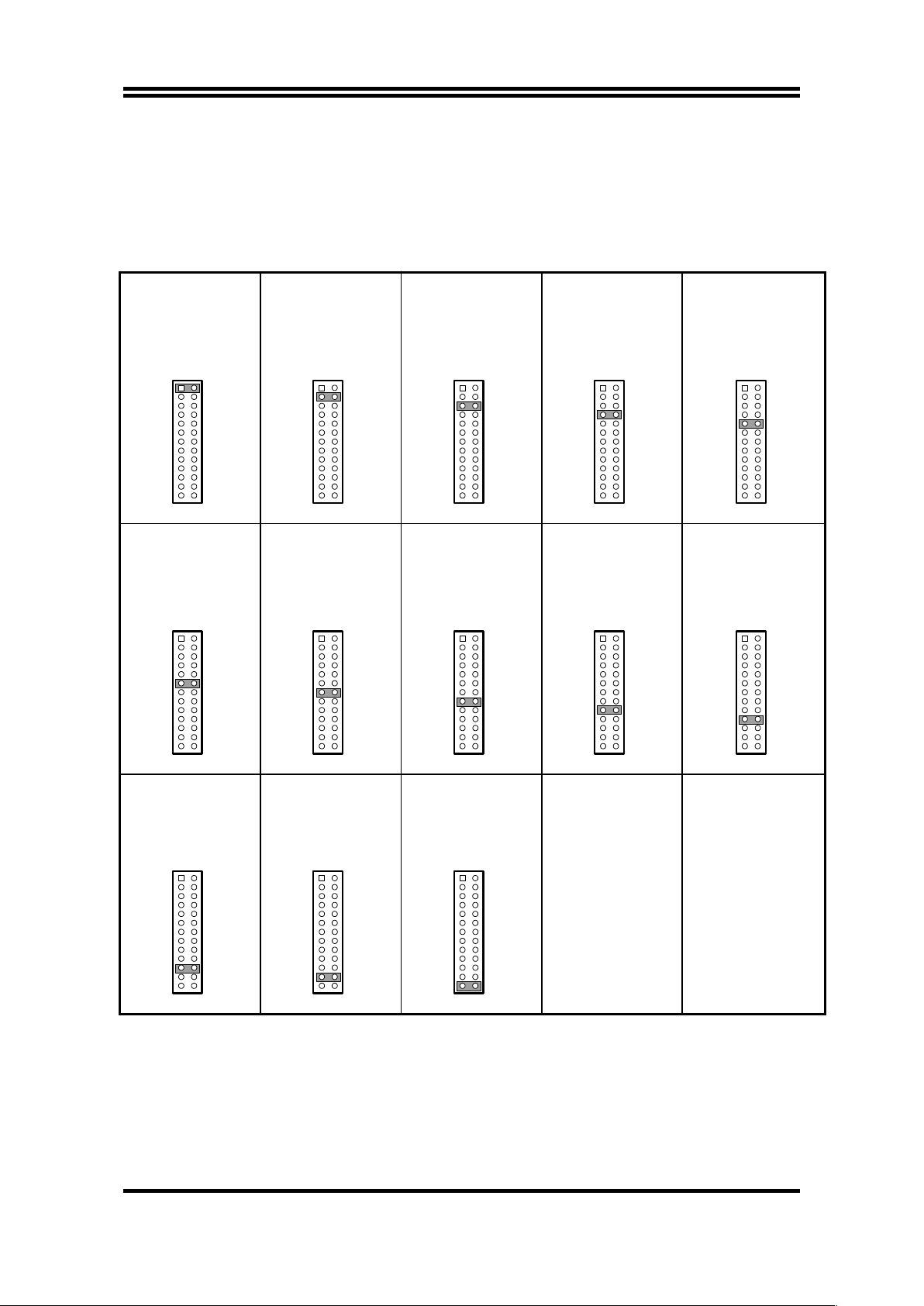
3. One Jumper Selection for CPU Type: J16 (Blue color selector)
CPU Type J16 Bus Frequency Clock Ratio
90MHz Pentium processor
1 & 2 short 60MHz 1.5x
AMD K5 PR-90
AMD K5 PR-100
AMD K5 PR-133
100MHz Pentium processor
233MHz Pentium processor
with MMX technology
3 & 4 short
66MHz 1.5x
120MHz Pentium processor 5 & 6 short 60MHz 2.0x
133MHz Pentium processor 7 & 8 short 66MHz 2.0x
150MHz Pentium processor
Cyrix 6x86MX-PR166
9 & 10 short 60MHz 2.5x
166MHz Pentium processor
11 & 12 short 66MHz 2.5x
166MHz Pentium processor
with MMX technology
AMD K5 PR-166
AMD K6 PR2-166
200MHz Pentium processor
Cyrix 6x86MX-PR233
13 & 14 short 66MHz 3.0x200MHz Pentium processor
with MMX technology
AMD K6 PR2-200
AMD K6 PR2-233 15 & 16 short 66MHz 3.5x
AMD K6 PR2-266 17 & 18 short 66MHz 4.0x
IDT C6-180MHz 19 & 20 short 60MHz 3.0x
Cyrix 6x86-150
+
21 & 22 short 60MHz 2.0x
IBM 6x86-150
+
Cyrix 6x86-166
+
23 & 24 short 66MHz 2.0x
IBM 6x86-166
+
Cyrix 6x86-200
+
Cyrix 6x86MX-PR200
25 & 26 short 75MHz 2.0x
IBM 6x86-200
+
IDT C6-150MHz
6
Page 9
NOTE: Before install the CPU, Please check the CPU Frequency and Clock Ratio
from your supplier.
For Cyrix 6X86MX series, please double check the CPU’s Frequency and
Clock Ratio.
75MHz CPU’s Bus Frequency is not in the reqular specification, therefore,
we are not recommend to use it.
AM
D K5 PR-90
90MHz Pentium processor
2
1
25
26
AMD K5 PR-100
AMD K5 PR-133
100MHz Pentium processor
233MHz Pentium processor
with MMX technology
2
1
25
26
120MHz Pentium processor
2
1
25
26
133MHz Pentium processor
2
1
25
26
150MHz Pentium processor
Cyrix 6x86MX-PR166
2
1
25
26
166MHz Pentium processor
166MHz Pentium processor
with MMX techlogy
AMD K5 PR-166
AMD K6 PR2-166
2
1
25
26
200MHz Pentium processor
200MHz Pentium processor
with MMX techlogy
Cyrix 6x86MX-PR233
AMD K6 PR2-200
2
1
25
26
AMD K6 PR2-233
2
1
25
26
AMD K6 PR2-266
2
1
25
26
IDT C6-180MHz
2
1
25
26
Cyrix 6x86-150
+
IBM 6x86-150
+
2
1
25
26
Cyrix 6x86-166
+
IBM 6x86-166
+
2
1
25
26
Cyrix 6x86-200
+
Cyrix 6x86MX-PR200
IBM 6x86-200
+
IDT C6-150MHz
2
1
25
26
7
Page 10
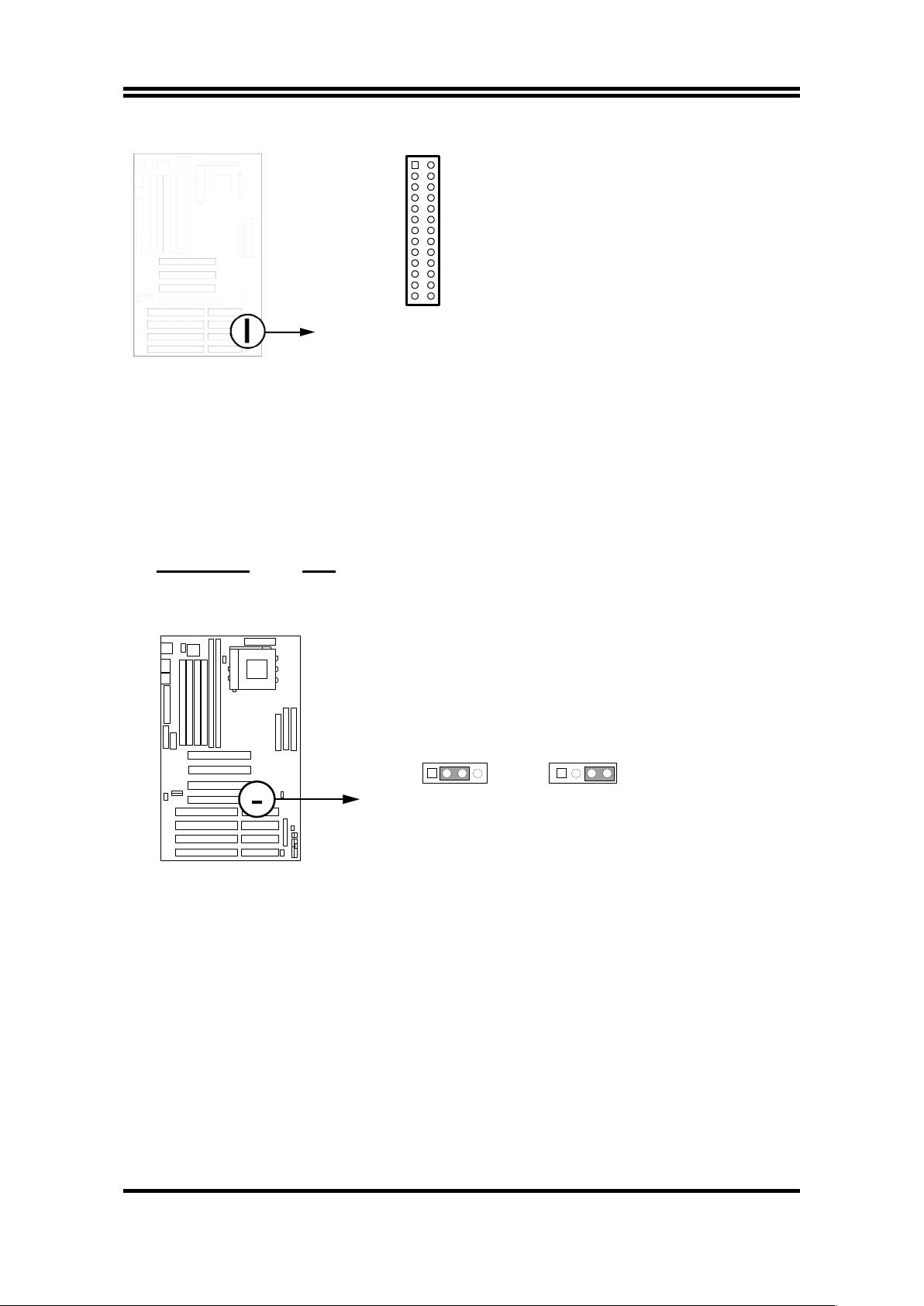
One Jumper Selection for CPU Type
2
1
25
26
INTEL 90MHz 1-2 short
AMD K6 266MHz 17-18 short
IDT C6-180MHz 19 -20 short
CYRIX 150+ 21-22 short
CYRIX 166+ 23-24 short
CYRIX 200+ 25-26 short
INTEL 100MHz 3-4 short
INTEL 133MHz 7-8 short
INTEL 150MHz 9-10 short
INTEL 166MHz 11-12 s hort
INTEL 200MHz 13-14 s hort
AMD K6 233MHz 15-16 short
INTEL 120MHz 5-6 short
4. CMOS RAM: JP6 (Yellow color selector)
This clears the user-entered information stored in the CMOS RAM chip such
as hard disk information and passwords. Simply connect a jumper cap over
this jumper for a few seconds then remove. But make sure that your computer
is power off. You must enter the BIOS setup (by holding down <DEL> during
power-up) after this is done to re-enter BIOS information (see BIOS SETUP)
Selections JP6
Normal 2-3 (Default)
Clear CMOS 3-4 (momentarily)
JP6
Normal
123
4
CMOS RAM (Normal / Clear CMOS Data)
JP6
Clear CMOS
123
4
2-2-2 System Memory (DRAM)
8
Page 11
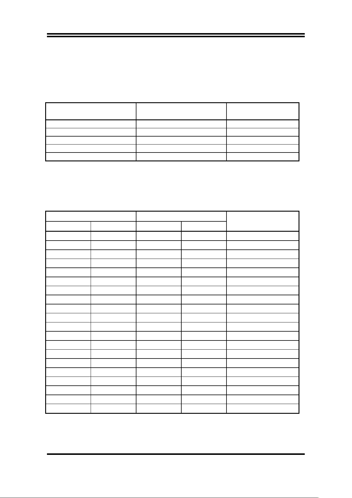
This motherboard supports four 72-pin SIMMs of 4MB, 8MB, 16MB, 32MB, or
64MB to from a memory size between 8MB to 256MB. The DRAM can be either
60ns or 70ns Fast Page Mode or EDO RAM. This motherboard also support two
168-pin DIMM Module, it can use only +3V unbuffer synchronous DRAM. The
Max. memory size is 256MB when use DIMM Module.
M5 M6 Total Memory
Combination
16MB 16MB 32MB
16MB 32MB 48MB
32MB 32MB 64MB
64MB 64MB 128MB
128MB 128MB 256MB
M5: BANK1, M6: BANK0
We don’t recommand use FAST PAGE/EDO Module with DIMM combination.
Install two memory modules each time as shown in the chart below.
Bank 0 Bank 1 Total Memory
M1 M2 M3 M4 Combination
4MB 4MB none none 8MB
4MB 4MB 4MB 4MB 16MB
8MB 8MB none none 16MB
8MB 8MB 4MB 4MB 24MB
8MB 8MB 8MB 8MB 32MB
16MB 16MB none none 32MB
16MB 16MB 4MB 4MB 40MB
16MB 16MB 8MB 8MB 48MB
16MB 16MB 16MB 16MB 64MB
32MB 32MB none none 64MB
32MB 32MB 4MB 4MB 72MB
32MB 32MB 8MB 8MB 80MB
32MB 32MB 16MB 16MB 96MB
32MB 32MB 32MB 32MB 128MB
64MB 64MB none none 128MB
64MB 64MB 4MB 4MB 136MB
64MB 64MB 8MB 8MB 144MB
64MB 64MB 16MB 16MB 160MB
64MB 64MB 32MB 32MB 192MB
64MB 64MB 64MB 64MB 256MB
2-3 Central Processing Unit (CPU)
9
Page 12
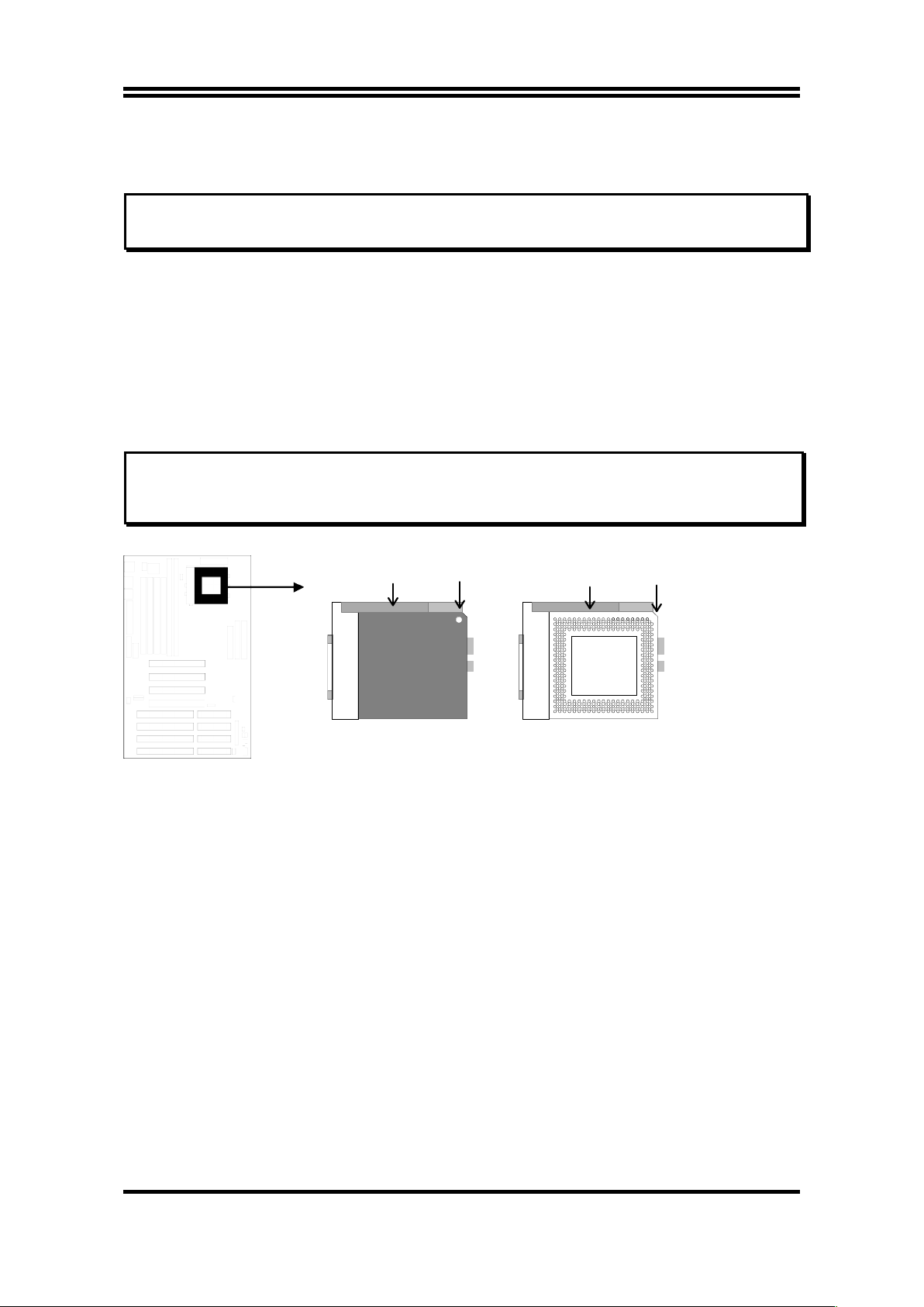
The motherboard provides a 321-pins ZIF Socket 7. The CPU on mother board
must have a fan attached to prevent overheating.
WARNING: Without a fan, the CPU will overheat and cause damage to both the CPU and
the motherboard.
To install a CPU, first turn off your system and remove its cover. Locate the ZIF
socket and open it by first pulling the lever sideways away from the socket then
upwards to a 90-degree right angle. Insert the CPU with the white dot as your
guide. The white dot should point towards the end of the level. The CPU has a
corner pin for three of the four corners, the CPU will only fit in the one orientation
as shown as follow. With the added weight of the CPU fan, no force is required to
insert the CPU. Once completely inserted, hold down on the fan and close the
socket’s lever.
IMPORTANT: You must set jumpers J16 “CPU One Jumper Setting” on and jumper JP1
“CPU I/O Voltage Selection” on page 5 depending on the CPU that you
install.
CPU ZIF Socket 7
Socket 7
Lock
Blank
Socket 7
Lever
White Dot
CPU
2-4 Expansion Cards
First read your expansion card documentation on any hardware and software
settings that may be required to setup your specific card.
Installation Procedure:
1. Read the documentation for your expansion card.
2. Set any necessary jumpers on your expansion card.
3. Remove your computer’s cover.
4. Remove the bracket on the slot you intend to use.
5. Carefully align the card’s connectors and press firmly.
6. Secure the card on the slot with the screw you remove in step 4.
7. Replace the computer’s cover.
8. Setup the BIOS if necessary.
9. Install the necessary software drivers for your expansion card.
10
Page 13

Assigning IRQs for Expansion Cards
Some expansion cards may require an IRQ to operate. Generally an IRQ must
be exclusively assigned to only one device. In an standard design there are 16
IRQs available but most of them are occupied by the system and leaves 6 free for
expansion cards.
Either ISA or PCI expansion cards may require an IRQs. System IRQs are
available to cards installed in the ISA expansion first, and any remaining IRQs
can be used by PCI cards. Currently, there are two types of ISA cards. An original
ISA expansion card design, know as “Legacy” ISA cards, they request configure
the card’s jumpers manually and then install it in any available slot on the ISA
bus, and other know as Plug and Play. You may use Microsoft’s Diagnostic
(MSD.EXE) utility included in the DOS directory to see a map of your used and
any free IRQs. For Windows 95 users, the “Control Panel” icon in “My
Computer”, contains a “System” icon which gives you “Device Manager” tab.
Double clicking on a specific device give you “Resources” tab which shows the
Interrupt number and address. Make sure that no any two of devices use the
same IRQs, or your computer will experience problems when those two devices
are in use at the same time.
To simplify this process the motherboard has complied with the Plug and Play
(PNP) specification which was developed to allow automatic system configuration
whenever a PNP-compliant card is added to the system. For PNP cards, IRQs
are assigned automatically from those available.
If the system has both Legacy and PNP ISA cards installed, IRQs are assigned to
PNP cards from those not used by Legacy cards. The PCI and PNP configuration
of the BIOS setup utility can be used to indicate which IRQs are being used by
Legacy cards. For older Legacy cards that does not work with the BIOS, you can
contact your vendor for an ISA Configuration Utility.
An IRQ number is automatically assigned to PCI expansion cards after those
used by Legacy and PNP ISA cards. In the PCI bus design, the BIOS automatically
assigns an IRQ to a PCI. To install a PCI card, you need to set something called
the INT (interrupt) assignment. Since all the PCI slots on this motherboard use
an INTA #, be sure that the jumpers on your PCI cards are set to INT A.
Assigning DMA Channels for ISA Cards
Some ISA cards, both Legacy and PNP may also need to use a DMA (Direct
Memory Access) channel. DMA assignments for this motherboard are handled
the same way as the IRQ assignment process described above. You can select
a DMA channel in the PCI and PNP configuration section of the BIOS Setup
utility. In the BIOS setup, you should choose “Yes” for those IRQ’s and DMA’s
you wish to reserve for Legacy cards.
2-5 External Connectors
1. ATX Power Connector (20-pins block): J13
11
Page 14
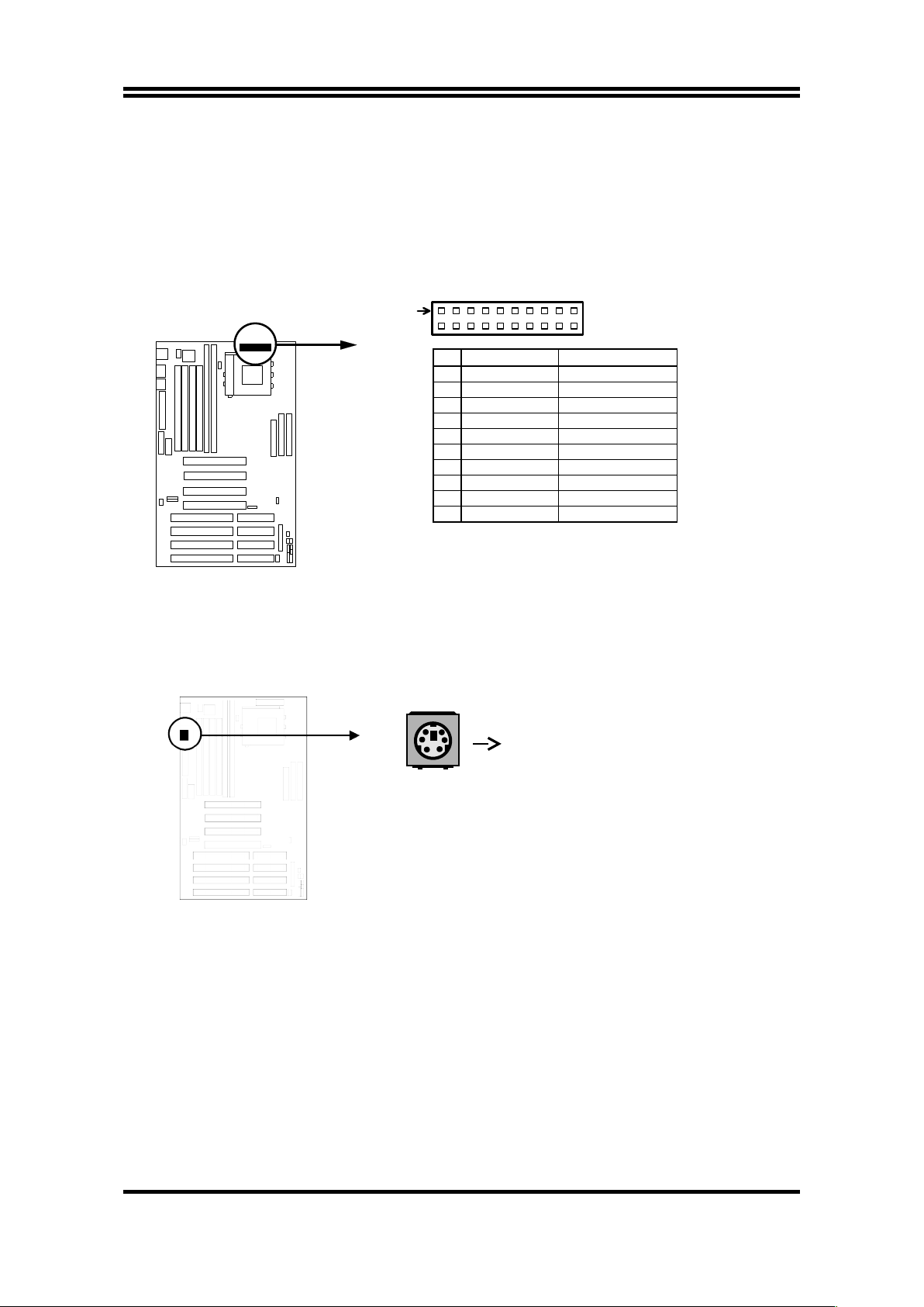
PS/2 Keyboard
ATX Power Supply connector. This is a new defined 20-pins connector that
usually comes with ATX case. The ATX Power Supply allows to use soft
power on momentary switch that connect from the front panel switch to 2-pins
Power On jumper pole on the motherboard. When the power switch on the
back of the ATX power supply turned on, the full power will not come into the
system board until the front panel switch is momentarily pressed. Press this
switch again will turn off the power to the system board.
PIN
ROW2
ROW1
1
3.3V
3.3V
2
-12V
3.3V
3
GND
GND
4
Soft Power On
5V
5
GND
GND
6
GND
5V
7
GND
GND
8
-5V
Power OK
9
+5V
+5V (for Soft Logic)
10
+5V
+12V
ATX Power Connector
Pin 1
2. PS/2 Keyboard Connector (6-pins female): KB
The PS/2 Keyboard connector is a 6-pins miniature DIN connector. It is for a
standard PS/2 style keyboard.
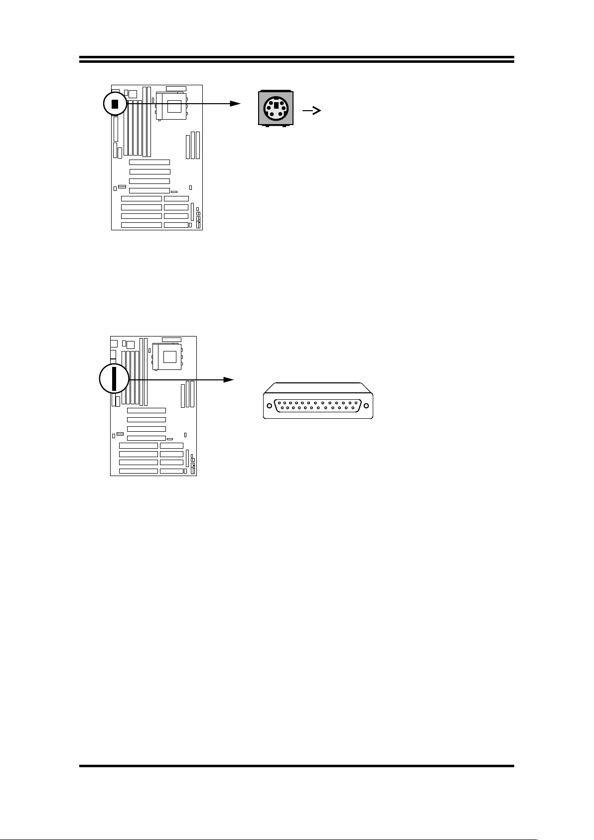
3. PS/2 Mouse Connector (6-pins female): MOUSE
The PS/2 Mouse is a 6-pins miniature DIN connector. It is for a standard PS/
2 style mouse.
12
Page 15
PS/2 Mouse
4. Parallel Port Connector (25-pins female): J3
Parallel Port connector is a 25-pins D-Subminiature Receptacle connector.
The On-board Parallel Port can be disabled through the BIOS SETUP.
Please refer to Chapter 3 “Peripheral Management Setup” section for more
detail information.
5. Serial Port COMA and COMB Connector: COM1 (J4), COM2 (J6)
COM1 (J4) is 9-pins D-subminiature male connector and COM2 (J6) connector
support the provided serial port ribbon cable with mounting bracket. Connect
the ribbon cable to this connector and mount the bracket to the case on an
open slot. The two serial ports will then be used for pointing devices or other
serial devices. See page 31 for BIOS configuration of “Onboard Serial Port”
13
Parallel Port Connector
Page 16
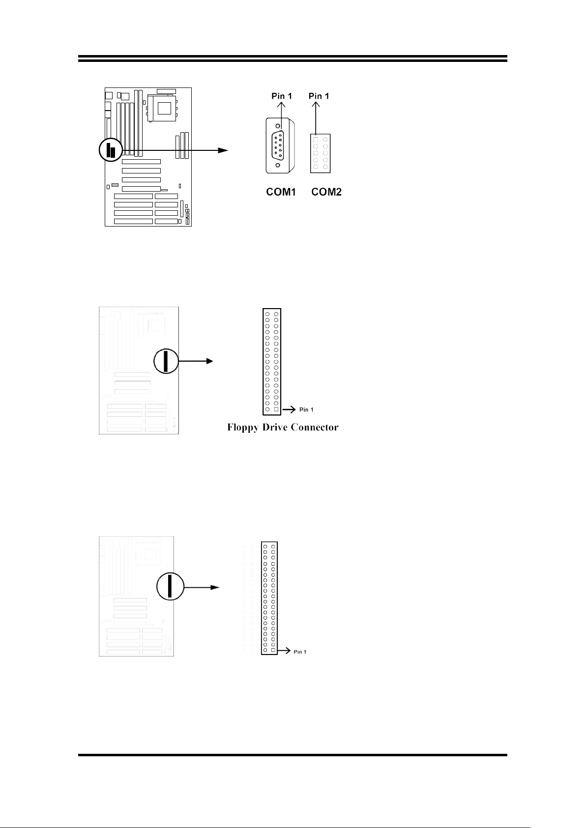
6. Floppy drive Connector (34-pins block): FDC. (J14)
This connector supports the provided floppy drive ribbon cable. After
connecting the single plug end to motherboard, connect the two plugs at other
end to the floppy drives.
7. Primary IDE Connector (40-pins block): PRIMARY IDE (J17)
This connector supports the provided IDE hard disk ribbon cable. After
connecting the single plug end to motherboard, connect the two plugs at other
end to your hard disk(s). If you install two hard disks, you must configure the
second drive to Slave mode by setting its jumpers accordingly. Please refer to
the documentation of your hard disk for the jumper settings.
8. Secondary IDE Connector (40-pins block): SECONDARY (J15)
This connector connects to the next set of Master and Slave hard disks.
Follow the same procedure described for the primary IDE connector. You
may also configure two hard disks to be both Masters using one ribbon cable
14
Serial Port COM1 & COM2 Connector
Page 17
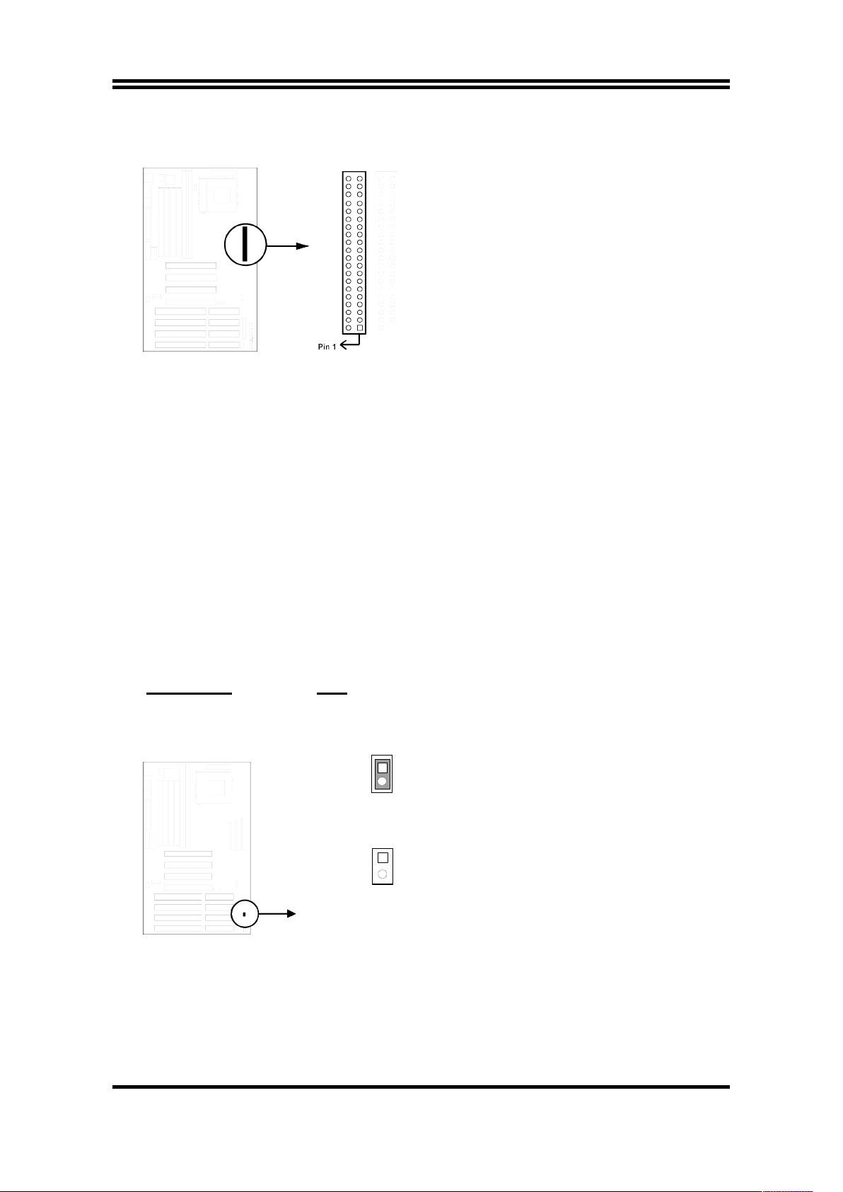
on the primary IDE connector and another ribbon cable on the secondary IDE
connector.
9. SMI suspend switch lead: SMI
This allows the user to manually place the system into a suspend mode or
“Green” mode where system activity will be instantly decreased to save
electricity and expand the life of certain components when the system is not
in use. This 2-pin connector (see the figure below) connects to the casemounted suspend switch. If you do not have a switch for the connector, you
may use the “Turbo Switch” since it does not have a function. SMI is activated
when it detects a short to open moment and therefore leaving it shorted will
not cause any problems. May require one or two pushes depending on the
position of the switch. Wake-up can be controlled by settings in the BIOS but
the keyboard will always allow wake-up (the SMI lead cannot wake-up the
system). If you want to use this connector, “Suspend Switch” in the POWER
MANAGEMENT SETUP of the BIOS software should be on the default
setting of Enable (see page 27).
Selections SMI
Enter suspend mode short
Normal open
Enter suspend mode
1
2
SMI
SMI
1
2
Normal
SMI suspend switch lead
10. Turbo LED switch: TB-LED
The motherboard‘s turbo function is always on. The turbo LED will remain
constantly lit while the system power is on. You may wish to connect the
Power LED from the system case to this lead. See the figure on page 16.
15
Page 18
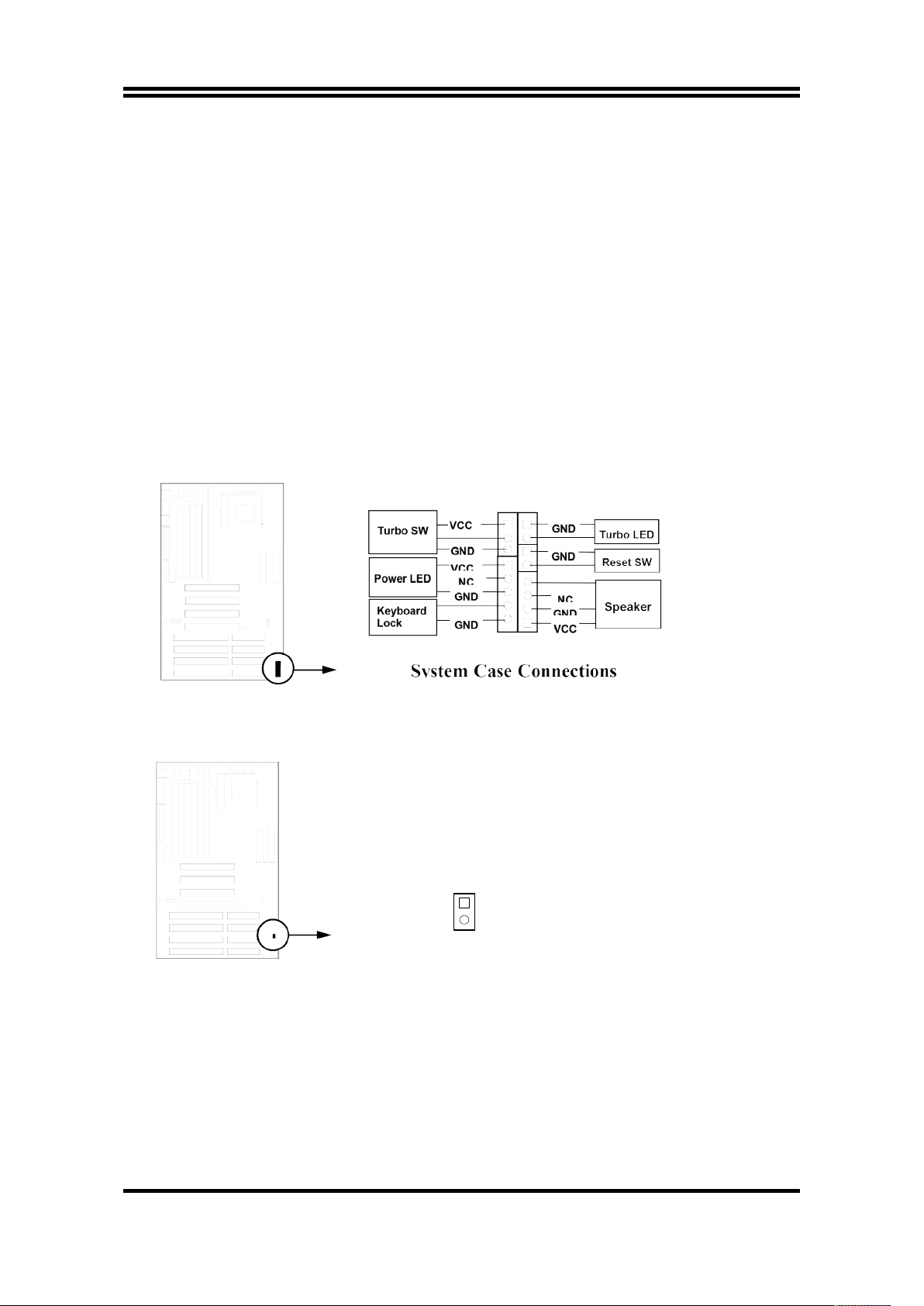
11. Reset switch lead: RESET
This 2-pin connector connects to the case-mounted reset switch for rebooting
your computer without having to turn off your power switch. This is a
preferred method of rebooting in order to prolong the life of the system‘s
power supply. See the figure below.
12. Keyboard lock switch lead: KEYLOCK
This 5-pin connector connects to the case-mounted key switch for locking the
keyboard for security purposes. See the figure below.
13. Speaker connector: SPEAKER
This 4-pin connector connects to the case-mounted speaker. See the figure
below.
14. IDE activity LED: HD-LED
This connector connects to the hard disk activity indicator light on the case.
HDLED
2
+
-
1
IDE (Hard Drive) LED
15. IR infrared module connector: JIR1
This connector supports the optional wireless transmitting and receiving
infrared module. This module mounts to small opening on system cases that
support this feature you must also configure the setting through BIOS setup.
Use the four pins as shown on the Back View and connect a ribbon cable from
the module to the motherboard according to the pin definitions.
16
Page 19
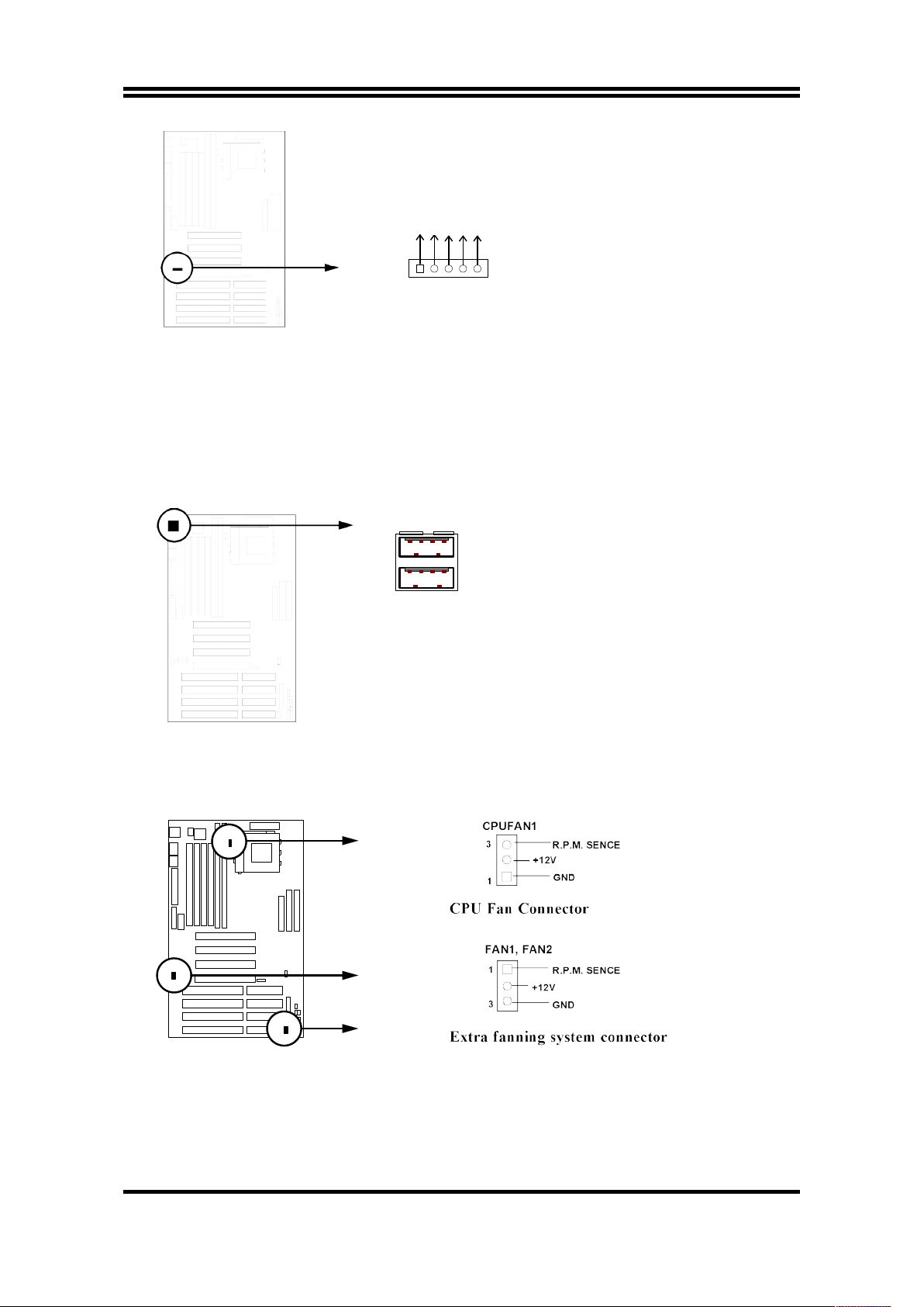
JIR1
Infrared Module Connector
NC
IRRX
GND
IRTX
VCC
16. Consumer IR module connector: JCIR1 (option)
Consumer infrared Module connector (option).
17. USB Port connector: USB (J5)
The connectors are 4-pins connector that connect USB devices to the system
board.
USB Port Connector
J5
18. CPU FAN connector: CPUFAN1,
Extra fanning system connector: FAN1, FAN2
CPUFAN1
FAN1
FAN2
19. Power-On button connector: JP7
17
Page 20
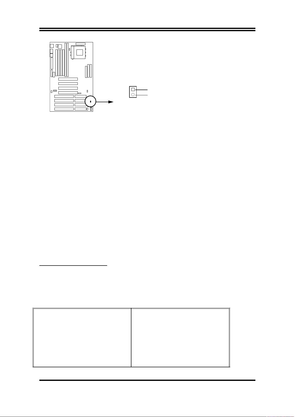
1
2
JP7
GND
Push Button
Power-On button connector
Chapter 3
AWARD BIOS SETUP
Award's ROM BIOS provides a built-in Setup program which allows user modify
the basic system configuration and hardware parameters. The modified data will
be stored in a battery-backed CMOS RAM so data will be retained even when the
power is turned off. In general, the information saved in the CMOS RAM stay
unchanged unless here is configuration change in the system, such as hard drive
replacement or new equipment is installed.
It is possible that CMOS had a battery failure which cause data lose in
CMOS_RAM. If so, re_enter system configuration parameters become necessary.
To enter Setup Program
Power on the computer and press <Del> key immediately will bring you into BIOS
CMOS SETUP UTILITY.
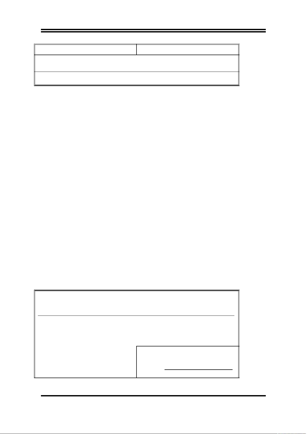
ROM PCI/ISA BIOS (2A59GJ19)
CMOS SETUP UTILITY
AWARD SOFTWARE, INC.
STANDARD CMOS SETUP
BIOS FEATURES SETUP
CHIPSET FEATURES SETUP
POWER MANAGEMENT SETUP
PNP/PCI CONFIGURATION
LOAD BIOS DEFAULTS
INTEGRATED PERIPHERALS
SUPERVISOR PASSWORD
USER PASSWORD
IDE HDD AUTO DETECTION
HDD LOW LEVEL FORMAT
SAVE & EXIT SETUP
18
Page 21
LOAD SETUP DEFAULTS EXIT WITHOUT SAVING
Esc : QUIT ↑↓→← : Select Item
F10 : Save & Exit Setup (Shift) F2 : Change Color
Time, Date, Hard Disk Type...
Figure 3-1
The menu displays all the major selection items and allow user to select any one
of shown item. The selection is made by moving cursor (press any direction key)
to the item and press <Enter> key. An on_line help message is displayed at the
bottom of the screen as cursor is moving to various items which provides user
better understanding of each function. When a selection is made, the menu of
selected item will appear so the user can modify associated configuration
parameters.
3-1 STANDARD CMOS SETUP
Choose "STANDARD CMOS SETUP" in the CMOS SETUP UTILITY Menu
(Figure 3-1). The STANDARD CMOS SETUP allows user to configure system
setting such as current date and time, type of hard disk drive installed in the
system, floppy drive type, and the type of display monitor. Memory size is autodetected by the BIOS and displayed for your reference. When a field is
highlighted (direction keys to move cursor and <Enter> key to select), the entries
in the field will be changed by pressing <PgDn> or <PgUp> keys or user can
enter new data directly from the keyboard.
ROM PCI/ISA BIOS (2A59GJ19)
STANDARD CMOS SETUP
AWARD SOFTWARE, INC.
Date (mm:dd:yy) : Fri, Jul, 11 1997
Time (hh:mm:ss) : 11 : 47 : 36
HARD DISKS TYPE SIZE CYLS HEAD PRECOMP LANDZ SECTOR MODE
Primary Master : Auto 0 0 0 0 0 0 Auto
Primary Slave : Auto 0 0 0 0 0 0 Auto
Secondary Master : Auto 0 0 0 0 0 0 Auto
Secondary Slave : Auto 0 0 0 0 0 0 Auto
Drive A : 1.2M , 5.25 in.
Drive B : None
Video : EGA/VGA
Halt On : All Errors
Base Memory : 640K
Extended Memory : 7168K
Other Memory : 384K
Total Memory : 8192K
19
Page 22

Esc : Quit ↑↓→← : Select Item Pu/Pd/+/- : Modify
F1 : Help (Shift)F2: Change Color
Figure 3-2
NOTE: If hard disk Primary Master/Slave and Secondary Master/Slave were used
Auto, than the hard disk size and model will be auto-detect on display during
POST.
NOTE: The "Halt On:" field is to determine when to halt the system by the BIOS is
error occurred during POST.
3-2 BIOS FEATURES SETUP
Select the "BIOS FEATURES SETUP" option in the CMOS SETUP UTILITY
menu allows user to change system related parameters in the displayed menu.
This menu shows all of the manufacturer's default values of this motherboard.
Again, user can move the cursor by pressing direction keys and <PgDn> of
<PgUp> keys to modify the parameters. Pressing [F1] key to display help
message of the selected item.
This setup program also provide 2 convinent ways to load the default parameter
data from BIOS [F6] or CMOS [F7] area if shown data is corrupted. This provides
the system a capability to recover from any possible error.
ROM PCI/ISA BIOS (2A59GJ19)
BIOS FEATURES SETUP
AWARD SOFTWARE, INC.
Virus Warning : Disabled
CPU Internal Cache : Enabled
External Cache : Enabled
Quick Power On Self Test : Disabled
Boot Sequence : A,C,SCSI
Swap Floppy Drive : Disabled
Boot Up Floppy Seek : Enabled
Boot Up Numlock Status : On
Boot Up System Speed : High
Gate A20 Option : Fast
Typematic Rate Setting : Disabled
Typematic Rate (Chars/Sec) : 6
Typematic Delay (Msec) : 250
Security Option : Setup
Video BIOS Shadow : Enabled
C8000-CBFFF Shadow : Disabled
CC000-CFFFF Shadow : Dsiabled
D0000-D3FFF Shadow : Disabled
D4000-D7FFF Shadow : Disabled
D8000-DBFFF Shadow : Disabled
DC000-DFFFF Shadow : Dsiabled
20
Page 23

PCI/VGA Palette Snoop : Disabled
OS Select For DRAM > 64MB : Non-OS2
Esc: Quit ↑↓→← : Select Item
F1 : Help Pu/Pd/+/-:Modify
F5 : Old Values (Shift)F2 : Color
F6 : Load BIOS Defaults
F7 : Load Setup Defaults
Figure 3-3
Note: The Security Option contains "setup" and "system". The "setup" indicates
that the password setting is for CMOS only while the "system" indicates the
password setting is for both CMOS and system boot up procedure.
Virus Warning: This category flashes on the screen. During and after the
system boots up, any attempt to write to the boot sector or partition table of
the hard disk drive will halt the system and the following error message will
appear, in the mean time, you can run an anti-virus program to locate the
problem. Default value is Disabled
Enabled: Activates automatically when the system boots up causing a
warning message to appear when anything attempts to access
the boot sector or hard disk partition table.
Disabled: No warning message to appear when anything attempts to
access the boot sector or hard disk partition table.
CPU Internal Cache / External Cache: These two categories speed up
memory access. However, it depends on CPU/chipset design. The default
value is Enable. If your CPU without Internal Cache then this item "CPU
Internal Cache" will not be show.
Enabled: Enable cachehis category speeds up Power On Self Test.
(POST) after you power on the computer.
Disabled: Disable cache
Quick Power On Self Test: If it is set to Enable, BIOS will shorten or skip
some check items during POST.
Enabled: Enable quick POST
Disabled: Normal POST
Boot Sequence: This category determines which drive computer searches
first for the DOS (Disk Operating System). Default value is A,C,SCSI.
System will first search for floppy disk drive, then hard disk drive and then
SCSI device. The options are: C, A, SCSI; C, CDROM, A; CDROM, C, A; D,
A, SCSI; E, A, SCSI; F, A, SCSI; SCSI, A, C; SCSI, C, A; C only; LS/ZIP, C.
21
Page 24

Swap Floppy Drive: The swap floppy drive. Default value is Disabled.
Enabled: Floppy A & B will be swapped under the DOS
Disabled: Floppy A & B will be not swap
Boot Up Floppy Seek: During POST, BIOS will determine if the floppy disk
drive installed is 40 or 80 tracks. 360K type is 40 tracks while 760K, 1.2M
and 1.44M are all 80 tracks. The default value is Enabled.
Enabled: BIOS searches for floppy disk drive to determine if it is 40 or 80
tracks.
Note that BIOS can not tell from 720K, 1.2M or 1.44M drive type
as they are all 80 tracks.
Disabled: BIOS will not search for the type of floppy disk drive by track
number.
Note that there will not be any warning message if the drive
installed is 360K.
Boot Up NumLock Status: The default value is On.
On: Keypad is number keys.
Off: Keypad is arrow keys.
Boot UP System Speed: It selects the default system speed-the speed that
the system will run at immediately after power up.
High: Set the speed to high.
Low: Set the speed to low.
NOTE: The board default value is LOW in the field. Boot the system to controller turbo
or De-turbo by Onboard (Turbo Switch).
Gate A20 Option: The default value is Fast.
Normal: The A20 signal is controlled by keyboard controller or chipset
hardware.
Fast: Default: Fast. The A20 signal is controlled by Port 92 or chipset
specific method.
Typematic Rate Setting: This determines the typematic rate.
Enabled: Enable typematic rate and typematic delay programming.
Disabled: Disable typematic rate and typematic delay programming. The
system BIOS will use default value of this 2 items and the default
is controlled by keyboard.
22
Page 25

Typematic Rate (Chars/Sec):
6 : 6 characters per second 8 : 8 characters per second
10 : 10 characters per second 12 : 12 characters per second
15 : 15 characters per second 20 : 20 characters per second
24 : 24 characters per second 30 : 30 characters per second
Typematic Delay (Msec): When holding a key, the time between the first
and second character displayed.
250 : 250 msec
500 : 500 msec
750 : 750 msec
1000 : 1000 msec
Security Option: This category allows you to limit access to the system and
Setup, or just to Setup. The default value is Setup.
System: The system will not boot and access to Setup will be denied if the
correct password is not entered at the prompt.
Setup: The system will boot, but access to Setup will be denied if the
incorrect password is entered at the prompt.
NOTE: To disable security, select PASSWORD SETTING at Main Menu and then
you will be asked to enter password. Do not type anything and just press
<Enter>, it will disable security. Once the security is disabled, the system will
boot and you can enter Setup freely.
Video BIOS Shadow: It determines whether video BIOS will be copied to
RAM, however, it is optional from chipset design. Video Shadow will increase
the video speed.
Enabled: Video shadow is enabled
Disabled: Video shadow is disabled
C8000 - CBFFF Shadow:
CC000 - CFFFF Shadow:
D0000 - D3FFF Shadow:
D4000 - D7FFF Shadow:
D8000 - DBFFF Shadow:
DC000 - DFFFF Shadow:
These categories determine whether optional ROM will be copied to RAM by
16K byte or 32K byte per/unit and the size depends on chipset.
Enabled: Optional shadow is enabled.
Disabled: Optional shadow is disabled.
23
Page 26

3-3 CHIPSET FEATURES SETUP
Choose the "CHIPSET FEATURES SETUP" in the CMOS SETUP UTILITY
menu to display following menu.
ROM PCI/ISA BIOS (2A59GJ19)
CHIPSET FEATURES SETUP
AWARD SOFTWARE, INC.
Auto Configuration : Enabled
DRAM Timing : 70 ns
DRAM Lead off Timing : 10/6/4
DRAM Read Burst (EDO/FP) : x333/x444
DRAM Write Burst Timing : x333
Fast EDO Lead Off : Disabled
Refresh RAS# Assertion : 5 Clks
Fast RAS To CAS Delay : 3
DRAM Page Idle Timer : 2 Clks
DRAM Enhanced Paging : Enabled
Fast MA to RAS# Delay : 2 Clks
SDRAM (CAS Lat/RAS-to-CAS: 3/3
SDRAM Speculative Read : Disabled
System BIOS Cacheable : Enabled
Video BIOS Cacheable : Enabled
8 Bit I/O Recovery Time : 1
16 Bit I/O Recovery Time : 2
Memory Hole At 15M-16M : Disabled
PCI 2.1 Compliance : Disabled
Esc: Quit ↑↓→←: Select Item
F1 : Help Pu/Pd/+/-:Modify
F5 : Old Values (Shift)F2 : Color
F6 : Load BIOS Defaults
F7 : Load Setup Defaults
Figure 3-4
DRAM Timing: The default value is 60ns.
24
Page 27

60ns : 2 (faster) Burst Wait State, for 60~70ns Fast Page Mode/EDO
DRAM.
70ns : 3 (slower) Burst Wait State, for 70ns Fast Page Mode/EDO DRAM.
Video BIOS Cacheable: The default value is Enabled.
Enabled: This field Enabled the Video BIOS Cacheable to speed up to
VGA Performance.
Disabled: Disabled the Video BIOS Cacheable function.
8/16 Bit I/O Recovery Time: The default value is 1.
8 Bit I/O Recovery Time: This field defines the recovery time from 1 to 8
for 8-bit I/O.
16 Bit I/O Recovery Time: To define the recovery time from 1 to 4 for 16-bit
I/O.
Memory Hole At 15M~16M:The default value is Disabled.
Disabled: Normal Setting.
Enabled: This field enableds the main memory (15~16MB) remap to ISA
BUS.
(Only in J-5TXA/L) For M/B with LM75 and LM78 on board
Choose the "CHIPSET FEATURES SETUP" in the CMOS SETUP UTILITY
menu to display following menu.
ROM PCI/ISA BIOS (2A59GJ19)
CHIPSET FEATURES SETUP
AWARD SOFTWARE, INC.
Auto Configuration : Enabled
DRAM Timing : 70 ns
DRAM Lead off Timing : 10/6/4
DRAM Read Burst (EDO/FP) : x333/x444
DRAM Write Burst Timing : x333
Fast EDO Lead Off : Disabled
Refresh RAS# Assertion : 5 Clks
Fast RAS To CAS Delay : 3
DRAM Page Idle Timer : 2 Clks
DRAM Enhanced Paging : Enabled
Fast MA to RAS# Delay : 2 Clks
SDRAM (CAS Lat/RAS-to-CAS: 3/3
SDRAM Speculative Read : Disabled
System BIOS Cacheable : Enabled
Video BIOS Cacheable : Enabled
8 Bit I/O Recovery Time : 1
16 Bit I/O Recovery Time : 2
Memory Hole At 15M-16M : Disabled
PCI 2.1 Compliance : Disabled
CPU Warning Temperature : Disabled
Current CPU Temperature : 27C/80F
Current System Temperature:26C/80F
Current CPUFAN Speed : 40/0 RPM
Core (V) : I/O (V):
12Volt : -12Volt:
-5Volt : 5Volt :
25
Page 28

Esc: Quit ↑↓→←: Select Item
F1 : Help Pu/Pd/+/-:Modify
F5 : Old Values (Shift)F2 : Color
F6 : Load BIOS Defaults
F7 : Load Setup Defaults
Figure 3-5
DRAM Timing: The default value is 60ns.
60ns : 2 (faster) Burst Wait State, for 60~70ns Fast Page Mode/EDO
DRAM.
70ns : 3 (slower) Burst Wait State, for 70ns Fast Page Mode/EDO DRAM.
Video BIOS Cacheable: The default value is Enabled.
Enabled: This field Enabled the Video BIOS Cacheable to speed up to
VGA Performance.
Disabled: Disabled the Video BIOS Cacheable function.
8/16 Bit I/O Recovery Time: The default value is 1.
8 Bit I/O Recovery Time: This field defines the recovery time from 1 to 8
for 8-bit I/O.
16 Bit I/O Recovery Time: To define the recovery time from 1 to 4 for 16-bit
I/O.
Memory Hole At 15M~16M:The default value is Disabled.
Disabled: Normal Setting.
Enabled: This field enableds the main memory (15~16MB) remap to ISA
BUS.
CPU Warning Temperature: If CPU’s temperature approach to setting
temperature, system will slow down automatically to reduce the CPU’s
temperature. The settings are 70, 66, 63, 60, 56, 53, 50 and Disabled.
Current CPU Temperature: Indicate the temperature of the CPU at present
time.
Current System Temperature: Indicate the temperature of entire system of
present time.
Core (V), I/O (V): Indicate the CPU’s Core Voltage and I/O Voltage.
12Volt, -12Volt, -5Volt, 5Volt: Indicate the voltage incoming for power
supply.
26
Page 29

3-4 POWER MANAGEMENT SETUP
Choose the "POWER MANAGEMENT SETUP" in the CMOS SETUP UTILITY to
display the following screen. This menu allows user to modify the power
management parameters and IRQ signals. In general, these parameters should
not be changed unless it's absolutely necessary.
ROM PCI/ISA BIOS (2A59GJ19)
POWER MANAGEMENT SETUP
AWARD SOFTWARE, INC.
Power Management : Disabled
PM Control by APM : Yes
Video Off Method : V/H SYNC+Blank
Video Off After : Stand by
MODEM Use IRQ : 3
Doze Mode : Disabled
Standby Mode : Disabled
Suspend Mode : Disabled
HDD Power Down : Disabled
Throttle Duty Cycle : 62.5%
ZZ Active in Suspend : Disabled
VGA Active Monitor : Enabled
Soft-Off by PWR-BTTN : Instant-Off
CPUFAN Off In Suspend : Enabled
Resume by Ring : Disabled
Resume by Alarm : Disabled
** Reload Global Timer Events **
IRQ [3-7, 9-15], NMI : Enabled
Primary IDE 0 : Disabled
Primary IDE 1 : Disabled
Secondary IDE 0 : Disabled
Secondary IDE 1 : Disabled
Floppy Disk : Disabled
Serial Port : Enabled
Parallel Port : Disabled
IRQ 8 Break Suspend : Disabled
Esc: Quit ↑↓→←: Select Item
F1 : Help Pu/Pd/+/-: Modify
F5 : Old Values (Shift)F2 : Color
F6 : Load BIOS Defaults
F7 : Load Setup Defaults
Figure 3-6
Again, user can move the cursor by pressing direction keys to the field need to be
modified and press <PgDn> or <PgUp> to alter item selection. You can only
27
Page 30

change the content of Doze Mode, Standby Mode, and Suspend Mode when the
Power Management is set to 'User Define'.
3-4-1 The Description of the Power Management
Power Management mode selection:
Disabled: The system operates in NORMAL conditions (Non-GREEN),
and the Power Management function is disabled.
Max.saving: This mode will maximize the power saving capability.
Min.saving: This mode will minimize the power saving capability.
User define: Allow user to define timeout parameters to control power
saving timing. Refer item shown below:
Timeout parameters:
HDD Standby
HDD Standby timer can be set from 1 to 15 minute(s).
System Doze
The "System Doze" mode timer starts to count when there is no "PM events"
occurred. The valid timeout setting is from 1 minute up to 1 hour.
System Standby
The "Standby" mode timer starts to count when "System Doze" mode timer timed
out and no "PM events" occurred. Valid range is from 1 minute up to 1 hour.
System Suspend
This function works only when the Pentium CPU is installed. The timer starts to
count when "System Standby" mode timer timed out and no "PM Events"
occurred. Valid range is from 1 minute up to 1 hour.
3-4-2 Description of the Green Functions
This motherboard supports HDD Power Down, Doze and standby power saving
functions when Intel Pentium Processor CPU is installed. The suspend function is
also supported when the SMI switch is short (ref. page 15). The detail description
of these functions are provided as following:
HDD Standby Mode
When system stop reading or writing HDD, the timer starts to count. The system
will cut off the HDD power when timer ran out of time. The system will not
resume operation until either a read from or a write to HDD command is executed
again.
Doze Mode
28
Page 31

The system hardware will drop down CPU clock from normal working speed when
Doze mode timeout occurred.
Standby Mode
When the system standby mode timer ran out, it will enter the standby mode and
retain CPU at slow working speed. The screen will be blanked out.
Suspend Mode
When the system suspend timer time out, the system will enter the suspend mode
and the chipset will stop CPU clock immediately. The power consunption in
Suspend Mode is lower than in standby mode. The screen is also blanked out.
PM Events:
AWARD BIOS defines 15 PM Events in the power management mode (Doze,
standby & suspend). The user can initial any PM Events to be "Enable" or
"Disable". When the system detects all of the enabled events do not have any
activity, it will start the system Doze timer first if the "Power Management" isn't
"Disabled". Once the system Doze timer timed out, it will process doze power
saving procedure by starting the system standby timer. When the standby timer
ran out and all of the "Enabled" events remains silent, the system will enter the
standby mode. By now, the system will not only process the standby power
saving procedures but also start the system suspend timer. When the suspend
timer time out, all of the CPU clock will be stopped by dropping system clock
down to zero and remains this way until any one of the "Enabled" event occurred.
3-5 PNP/PCI CONFIGURATION SETUP
This “PNP and PCI configuration Setup” option configures the PCI bus slots. All
PCI bus slots on the system use INTA#, thus all installed PCI cards must be set
to this value.
ROM PCI/ISA BIOS (2A59GJ19)
PNP/PCI CONFIGURATION SETUP
AWARD SOFTWARE, INC.
PNP OS Installed : No
Resources Controlled By : Manual
Reset Configuration Data: Disabled
IRQ-3 assigned to : Legacy ISA
IRQ-4 assigned to : Legacy ISA
IRQ-5 assigned to : PCI/ISA PnP
IRQ-7 assigned to : PCI/ISA PnP
IRQ-9 assigned to : PCI/ISA PnP
IRQ-10 assigned to : PCI/ISA PnP
PCI IDE IRQ Map To : PCI-AUTO
Primary IDE INT# : A
Secondary IDE INT# : B
Used MEM Base Addr : N/A
29
Page 32

IRQ-11 assigned to : PCI/ISA PnP
IRQ-12 assigned to : PCI/ISA PnP
IRQ-14 assigned to : PCI/ISA PnP
IRQ-15 assigned to : PCI/ISA PnP
DMA-0 assigned to : PCI/ISA PnP
DMA-1 assigned to : PCI/ISA PnP
DMA-3 assigned to : PCI/ISA PnP
DMA-5 assigned to : PCI/ISA PnP
DMA-6 assigned to : PCI/ISA PnP
DMA-7 assigned to : PCI/ISA PnP Esc: Quit ↑↓→←: Select Item
F1 : Help Pu/Pd/+/-:Modify
F5 : Old Values (Shift)F2 : Color
F6 : Load BIOS Defaults
F7 : Load Setup Defaults
Figure 3-7
IRQxx assigned to
These fields indicate whether or not the displayed IRQ for each field is being used
by a Legacy (non-PnP) ISA card. Two options are available: “PCI/ISA PnP” and
“Legacy ISA”. The first option the default value, indicates either that the displayed
IRQ is not used or an PCI/ISA PnP is being used to determine if an ISA card is
using that IRQ. Second option is for Legacy ISA card that requires a unique IRQ,
and you are not using an PCI/ISA PnP, you must set the field for that IRQ to
Legacy ISA.
For example: If you install a Legacy ISA card that requires IRQ10 lets say, then
set “IRQ10 assigned to Legacy ISA”.
DMAxx assigned to
These fields indicate whether or not the displayed DMA channel for each field is
being used by a Legacy (non-PnP) ISA card. Available options include: “PCI/ISA
PnP” and ”Legacy ISA“. When is option ”PCI/ISA PnP“ indicates either that the
displayed DMA channel is not used or an PCI/ISA PnP being used to determine if
an ISA card is using that channel. If you install a Legacy ISA card that requires a
unique DMA channel, and you are not using an PCI/ISA PnP, you must set the
field for that channel to “Legacy ISA“.
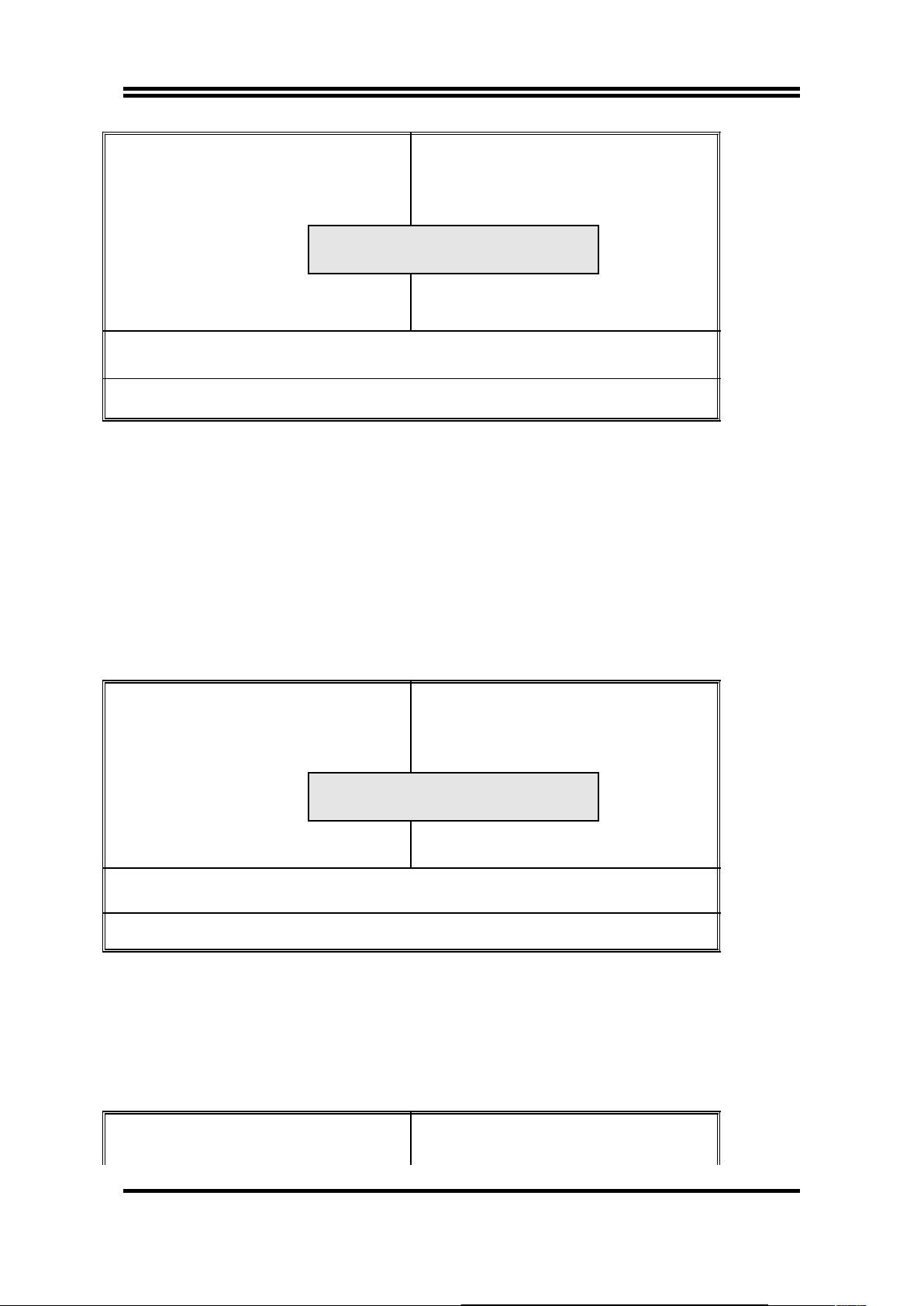
3-6 LOAD BIOS DEFAULTS
The "LOAD BIOS DEFAULTS" function loads the system default data directly
from ROM and initialize associated hardware properly. This function will be
necessary only when the system CMOS data is corrupted.
ROM PCI/ISA BIOS (2A59GJ19)
CMOS SETUP UTILITY
AWARD SOFTWARE, INC.
30
Page 33
STANDARD CMOS SETUP
BIOS FEATURES SETUP
CHIPSET FEATURES SETUP
POWER MANAGEMENT
PNP/PCI CONFIGURA
LOAD BIOS DEFAULTS
LOAD SETUP DEFAULTS
INTEGRATED PERIPHERALS
SUPERVISOR PASSWORD
USER PASSWORD
TECTION
ORMAT
SAVE & EXIT SETUP
EXIT WITHOUT SAVING
Esc : QUIT ↑↓→← : Select Item
F10 : Save & Exit Setup (Shift) F2 : Change Color
Time, Date, Hard Disk Type...
Figure 3-8
3-7 LOAD SETUP DEFAULTS
The "LOAD SETUP DEFAULTS" function loads the system default data directly
from ROM and initialize associated hardware properly. This function will be
necessary only when the system CMOS data is corrupted.
ROM PCI/ISA BIOS (2A59GJ19)
CMOS SETUP UTILITY
AWARD SOFTWARE, INC.
STANDARD CMOS SETUP
BIOS FEATURES SETUP
CHIPSET FEATURES SETUP
POWER MANAGEMENT
PNP/PCI CONFIGUR
LOAD BIOS DEFAULTS
LOAD SETUP DEFAULTS
INTEGRATED PERIPHERALS
SUPERVISOR PASSWORD
USER PASSWORD
TECTION
ORMAT
SAVE & EXIT SETUP
EXIT WITHOUT SAVING
Esc : QUIT ↑↓→← : Select Item
F10 : Save & Exit Setup (Shift) F2 : Change Color
Time, Date, Hard Disk Type...
Figure 3-9
3-8 INTEGRATED PERIPHERALS SETUP
ROM PCI/ISA BIOS (2A59GJ19)
INTEGRATED PERIPHERALS
AWARD SOFTWARE, INC.
IDE HDD Block Mode : Enabled
IDE Primary Master PIO : Auto
IDE Primary Salve PIO : Auto
Onboard Parallel Port : 378/IRQ7
Parallel Port Mode : SPP
31
Load BIOS Default (Y/N)? Y
Load SETUP Default (Y/N)? Y
Page 34

IDE Secondary Master PIO : Auto
IDE Secondary Slave PIO : Auto
IDE Primary Master UDMA : Auto
IDE Primary Slave UDMA : Auto
IDE Secondary Master UDMA: Auto
IDE Secondary Slave UDMA : Auto
On-Chip Primary PCI IDE: Enabled
On-Chip Secondary PCI IDE: Enabled
USB Keyboard Support : Disabled
Onboard FDC Controller : Enabled
Onboard SERIAL PORT 1 : Auto
Onboard SERIAL PORT 2 : Auto
UR2 Mode : Normal
Esc: Quit ↑↓→←: Select Item
F1 : Help Pu/Pd/+/-:Modify
F5 : Old Values (Shift)F2 : Color
F6 : Load BIOS Defaults
F7 : Load Setup Defaults
Figure 3-10
NOTE: If you don't use the Onboard IDE connector, than use On-card (PCI or ISA card)
IDE connector. You will set Onboard Primary IDE: Disabled an Onboard Secondary
IDE: Disabled from CHIPSET FEATURES SETUP UTILITY.
The Onboard PCI IDE cable should be equal to or less than 18 inches (45 cm).
IDE HDD Block Mode: The default value is Enabled.
Enabled: Enabled IDE HDD Block Mode. The HDD transfer rate is better
than Disable.
Disabled: Disable IDE HDD Block Mode.
IDE Primary Master PIO: The default value is Auto.
Auto: BIOS will automatically detect the Onboard Primary Master PCI
IDE HDD Accessing mode.
Mode0~4: Manually set the IDE Accessing mode.
IDE Primary Slave PIO: The default value is Auto.
Auto: BIOS will automatically detect the Onboard Primary Slave PCI
IDE HDD Accessing mode.
Mode0~4: Manually set the IDE Accessing mode.
IDE Secondary Master PIO: The default value is Auto.
Auto: BIOS will automatically detect the Onboard Secondary Master
PCI IDE HDD Accessing mode.
Mode0~4: Manually set the IDE Accessing mode.
IDE Secondary Slave PIO: The default value is
Auto: BIOS will automatically detect the Onboard Secondary Slave PCI
IDE HDD Accessing mode.
Mode0~4: Manually set the IDE Accessing mode.
32
Page 35

Onboard Primary PCI IDE: The default value is Enabled.
Enabled: Enable Onboard 1 st channel IDE port.
Disabled: Disable Onboard 1 st channel IDE port. When use On-card (PCI
or ISA card) IDE connector.
Onboard Secondary PCI IDE: The default value is Enabled.
Enabled: Enable Onboard 2 nd channel IDE port.
Disabled: Disable Onboard 2 nd channel IDE port. When use On-card (PCI
or ISA card) IDE connector.
PCI Slot IDE 2nd Channel: The default value is Enabled.
Enabled: Enable secondary IDE port and BIOS will assign IRQ15 for this
port.
Disabled: Disable secondary IDE port and IRQ15 is available for other
device.
Onboard FDC Controller: The default value Enabled.
Enabled: Enable the Onboard floppy drive interface controller.
Disabled: Disable the Onboard floppy drive interface controller. When use
On-card ISA FDC's controller.
Onboard Serial Port 1: This field allows the user to select the serial port. The
default value is COM1.
COM1: Enable Onboard Serial port 1 and address is 3F8H.
COM2: Enable Onboard Serial port 1 and address is 2F8H.
COM3: Enable Onboard Serial port 1 and address is 3E8H.
COM4: Enable Onboard Serial port 1 and address is 2E8H.
Disabled: Disable Onboard SMC CHIP's Serial port 1.
Onboard Serial port 2: This field allows the user to select the serial port.
The default value is COM2.
COM1: Enable Onboard Serial port 2 and address is 3F8H.
COM2: Enable Onboard Serial port 2 and address is 2F8H.
COM3: Enable Onboard Serial port 2 and address is 3E8H.
COM4: Enable Onboard Serial port 2 and address is 2E8H.
Disabled: Disable Onboard SMC CHIP's Serial port 2.
Onboard Parallel port: This field allows the user to select the LPT port. The
default value is 378H.
378H: Enable Onboard LPT port and address is 378H.
278H: Enable Onboard LPT port and address is 278H.
3BCH: Enable Onboard LPT port and address is 3BCH.
Disabled: Disable Onboard SMC CHIP's LPT port.
33
Page 36

NOTE: Parallel Port address is 378H/3BCH that selects the rounting of IRQ7 for LPT1.
Parallel Port address is 278H that selects the rounting of IRQ5 LPT1.
Onboard Parallel port Mode: This field allows the user to select the parallel
port mode. The default value is ECP + EPP.
Normal: Standard mode. IBM PC/AT Compatible bidirectional parallel
port.
EPP: Enhanced Parallel Port mode.
ECP: Extended Capabilities Port mode.
EPP+ECP: ECP Mode & EPP Mode.
3-9 SUPERVISOR/USER PASSWORD
This item lets you configure the system so that a password is required each time
the system boots or an attempt is made to enter the Setup program (Refer to
Figure 3-3 for the details). Supervisor Password allows you to change all CMOS
settings but the User Password setting doesn’t have this function. The way to set
up the passwords for both Supervisor and User are as follow:
1. Choose either Supervisor Password or User Password in the Main Menu and
press <Enter>. The following message appears:
“Enter Password:”
2. The first time you run this option, enter your password up to only 8 characters
and press <Enter>. The screen does not display the entered characters. For
no password just press <Enter>.
3. After you enter the password, the following message appears prompting you
to confirm the password:
“Confirm Password:”
4. Enter exact the same password you just typed again to confirm the password
and press <Enter>.
5. Move the cursor to Save & Exit Setup to save the password.
6. If you need to delete the password you entered before, choose the Supervisor
Password and Press <Enter>. It will delete the password that you bad before.
7. Move the cursor to Save & Exit Setup to save the option you did, otherwise
the old password will still be there when you turn on your machine next time.
34
Page 37
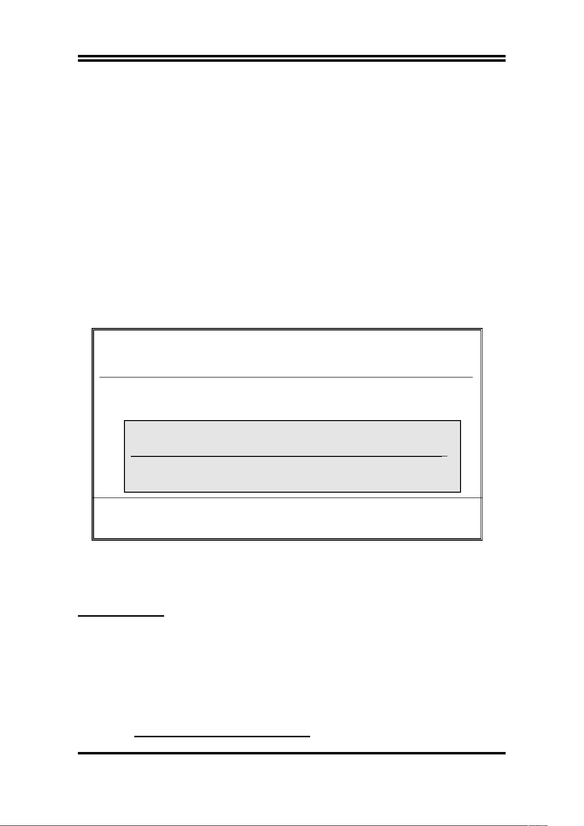
3-10 IDE HDD AUTO DETECTION
The "IDE HDD AUTO DETECTION" utility is a very useful tool especially when
you do not know which kind of hard disk type you are using. You can use this
utility to detect the correct disk type and install in the system automatically. Also
you can set HARD DISK TYPE to “Auto” in the STANDARD CMOS SETUP to
have same result. The BIOS will Auto-detect the hard disk size and model on
display during POST.
ROM PCI/ISA BIOS (2A59GJ19)
STANDARD CMOS SETUP
AWARD SOFTWARE, INC.
Date (mm:dd:yy) : Fri, Jul, 11 1997
Time (hh:mm:ss) : 11 : 47 : 36
HARD DISKS TYPE SIZE CYLS HEAD PRECOMP LANDZ SECTOR MODE
Primary Master :
Primary Slave :
Secondary Master :
Sec
Esc : Quit ↑↓→← : Select Item Pu/Pd/+/- : Modify
F1 : Help (Shift)F2: Change Color
Figure 3-11
NOTE: HDD Modes
The Award BIOS supports 3 HDD modes : NORMAL, LBA & LARGE
NORMAL mode
Generic access mode in which neither the BIOS nor the IDE controller will make
any transformations during accessing.
The maximum number of cylinders, head & sectors for NORMAL mode are 1024,
16 & 63.
no. Cylinder (1024)
x no. Head ( 16)
x no. Sector ( 63)
x no. per sector ( 512)
35
Select Secondary Slave Option (N=Skip):N
OPTIONS SIZE CYLS HEAD PRECOMP LANDZ SECTOR MODE
1 (Y) 0 0 0 0 0 0 NORMAL
Page 38

528 Megabytes
If user set this HDD to NORMAL mode, the maximum accessible HDD size will be
528 Megabytes even though its physical size may be greater than that!
LBA (Logical Block Addressing) mode
A new HDD accessing method to overcome the 528 Megabyte bottleneck. The
number of cylinders, heads & sectors shown in setup may not be the number
physically contained in the HDD.
During HDD accessing, the IDE controller will transform the logical address
described by sector, head & cylinder into its own physical address inside the
HDD.
The maximum HDD size supported by LBA mode is 8.4 Gigabytes which is
obtained by the following formula:
no. Cylinder (1024)
x no. Head ( 255)
x no. Sector ( 63)
x bytes per sector ( 512)
8.4 Gigabytes
LARGE mode
Extended HDD access mode supported by Award Software.
Some IDE HDDs contain more than 1024 cylinder without LBA support (in some
cases, user do not want LBA). The Award BIOS provides another alternative to
support these kinds of LARGE mode:
CYLS. HEAD SECTOR MODE
1120 16 59 NORMAL
560 32 59 LARGE
BIOS tricks DOS (or other OS) that the number of cylinders is less than 1024 by
dividing it by 2. At the same time, the number of heads is nultiplied by 2. Reverse
transformation process will be made inside INT 12h in order to access the right
HDD address the right HDD address!
Maximum HDD size:
no. Cylinder (1024)
x no. Head ( 32)
x no. Sector ( 63)
x bytes per sector ( 512)
1 Gigabytes
NOTE:
To support LBA or LARGE mode of HDDs, there must be some softwares involved. All
these softwares are located in the Award HDD Service Routine (1NT 13h). It may be
36
Page 39
failed to access a HDD with LBA (LARGE) mode selected if you are running under a
Operating System which replaces the whole INT 13h.
UNIX operating systems do not support either LBA or LARGE and must set to the
Standard mode. UNIX can support drives larger than 528MB.
3-11 SAVE & EXIT SETUP
The "SAVE & EXIT SETUP" option will bring you back to boot up procedure with
all the changes you just made which are recorded in the CMOS RAM.
3-12 EXIT WITHOUT SAVING
The "EXIT WITHOUT SAVING" option will bring you back to normal boot up
procedure without saving any data into CMOS RAM. All of the old data in the
CMOS will not be destroyed.
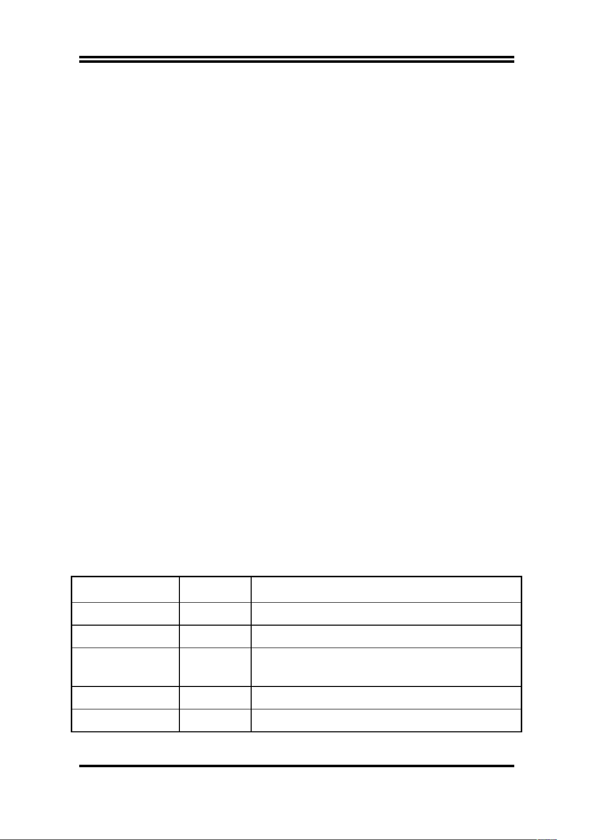
3-13 I/O & MEMORY MAP
MEMORY MAP
Address Range Size Description
00000-7FFFF 512K Conventional memory
80000-9FBFF 127K Extended Conventional memory
9FC00-9FFFF 1K Extended BIOS data area if PS/2 mouse is
installed
A0000-C7FFF 160K Available for Hi DOS memory
C8000-DFFFF 96K Available for Hi DOS memory and adapter ROMs
37
Page 40

E0000-EEFFF 60K Available for UMB
EF000-EFFFF 4K Video service routine for Monochrome & CGA
adapter
F0000-F7FFF 32K BIOS CMOS setup utility
F8000-FCFFF 20K BIOS runtime service routine (2)
FD000-FDFFF 4K Plug and Play ESCD data area
FE000-FFFFF 8K BIOS runtime service routine (1)
I/O MAP
000-01F DMA controller (Master)
020-021 INTERRUPT CONTROLLER (Master)
022-023 CHIPSET control registers. I/O ports
040-05F TIMER control registers
060-06F KEYBOARD interface controller (8042)
070-07F RTC ports & CMOS I/O ports
080-09F DMA register
0A0-0BF INTERRUPT controller (Slave)
0C0-0DF DMA controller (Slave)
0F0-0FF MATH COPROCESSOR
1F0-1F8 HARD DISK controller
278-27F PARALLEL port 2
2B0-2DF GRAPHICS adapter controller
2F8-2FF SERIAL port 2
360-36F NETWORK ports
378-37F PARALLEL port 1
3B0-3BF MONOCHROME & PARALLEL port adapter
3C0-3CF EGA adapter
3D0-CDF CGA adapter
38
Page 41

3F0-3F7 FLOPPY DISK controller
3F8-3FF SERIAL port-1
3-14 TIME & DMA CHANNELS MAP
TIME MAP: TIMER Channel 0 System timer interrupt
TIMER Channel 1 DRAM REFRESH request
TIMER Channel 2 SPEAKER tone generator
DMA CHANNELS: DMA Channel 0 Available
DMA Channel 1 Onboard ECP (Option)
DMA Channel 2 FLOPPY DISK (SMC CHIP)
DMA Channel 3 Onboard ECP (Default)
DMA Channel 4 Cascade for DMA controller 1
DMA Channel 5 Available
DMA Channel 6 Available
DMA Channel 7 Available
3-15 INTERRUPT MAP
NMI: Parity check error
IRQ (H/W): 0 System TIMER interrupt from TIMER 0
1 KEYBOARD output buffer full
2 Cascade for IRQ 8-15
3 SERIAL port 2
4 SERIAL port 1
5 PARALLEL port 2
6 FLOPPY DISK (SMC CHIP)
39
Page 42

7 PARALLEL port 1
8 RTC clock
9 Available
10 Available
11 Available
12 PS/2 Mouse
13 MATH coprocessor
14 Onboard HARD DISK (IDE1) channel
15 Onboard HARD DISK (IDE2) channel
3-16 RTC & CMOS RAM MAP
RTC & CMOS: 00 Seconds
01 Second alarm
02 Minutes
03 Minutes alarm
04 Hours
05 Hours alarm
06 Day of week
07 Day of month
08 Month
09 Year
0A Status register A
0B Status register B
0C Status register C
0D Status register D
0E Diagnostic status byte
0F Shutdown byte
10 FLOPPY DISK drive type byte
11 Reserve
12 HARD DISK type byte
13 Reserve
14 Equipment type
15 Base memory low byte
16 Base memory high byte
17 Extension memory low byte
18 Extension memory high byte
19-2d
40
Page 43

2E-2F
30 Reserved for extension memory low byte
31 Reserved for extension memory high byte
32 DATE CENTURY byte
33 INFORMATION FLAG
34-3F Reserve
40-7F Reserved for CHIPSET SETTING DATA
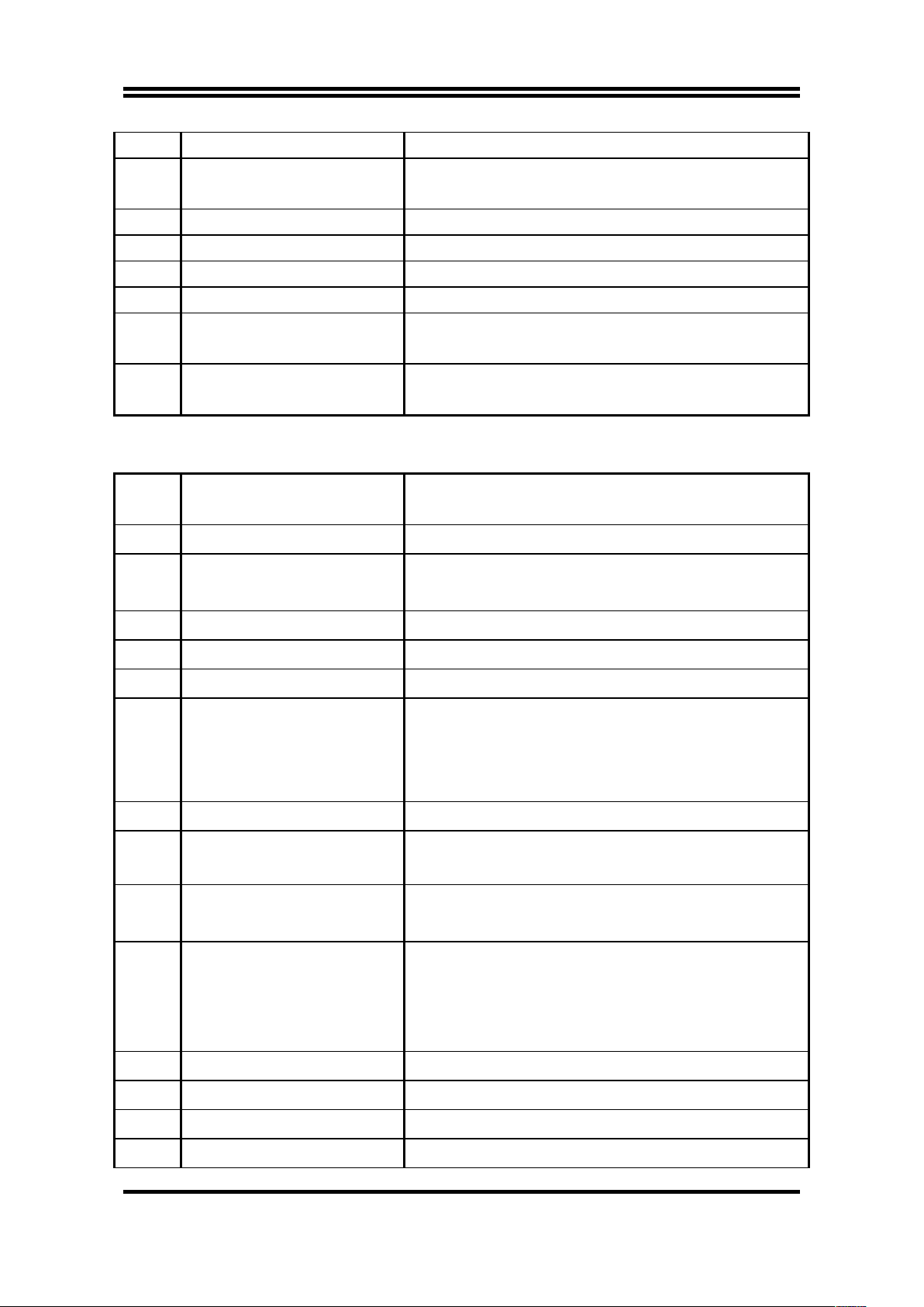
3-17 BIOS REFERENCE-POST CODES
ISA PORT codes are typically output to port address 80h.
Post Name
Description
CO Turn Off Chipset Cache
OEM Specific-Cache controller.
1 Processor Test 1
Processor Status (1 FLAGS) Verification.
Tests the following processor status flags carry,
zero, sign, overflow.
The BIOS will set each of these flags, verify the are
set, then turn each flag off and verify it is off.
2 Processor Test 2
Read/ Write/ Verify all CPU registers except SS, SP,
and BP with data pattern FF and OO.
3 Initialize Chips
Disable NMI, PIE, AIE, UEI, SOWV.
Disable video, parity checking, DMA.
Reset math coprocessor.
Clear all page registers, CMOS shutdown byte.
Initialize timer 0, 1, and 2, including set EISA timer
to a known state.
Initialize DMA Controllers 0 and 1.
Initialize interrupt controllers 0 and 1.
Initialize EISA extended registers.
4 Test Memory Refresh
Toggle
RAM must be periodically refreshed inorder to keep
the memory from decaying.
This function assures that the memory refresh
function is working properly.
5 Blank video, Initialize
Keyboard controller initialization.
41
Page 44

keyboard
6 Reserved
7 Test CMOS Interface and
Battery Status
Verifies CMOS is working correctly, detects bad
battery.
BE
Chipset Default
Initialization
Program chipset registers with power on BIOS
defaults.
C1 Memory presence test
OEM Specific-Test to size on-board memory.
C5 Early Shadow OEM Specific-Early Shadow enable for fast boot.
C6 Cache presence test External cache size detection.
8 Setup low memory
Early chip set initialization.
Memory presence test.
OEM chip set routines.
Clear low 64K of memory.
Test first 64K memory.
9
Early Cache
Initialization
Cyrix CPU initialization.
Cache initialization.
A Setup Interrupt Vector Table
Initialization first 120 interrupt vectors with
SPURIOUS_INT_HDLR and initialize INT 00h-1Fh
according to INT_TBL
B Test CMOS RAM Checksum
Test CMOS RAM Checksum, if bad, or insert key
pressed, load defaults.
C Initialize keyboard
Detect type of keyboard controller (optional) Set
NUM_LOCK status.
D Initialize Video Interface
Detect CPU clock.
Read CMOS location 14h to find out type of video in
use.
Detect and Initialize Video Adapter.
E Test Video Memory
Test video memory, write sign-on message to
screen.
Setup shadow RAM.Enable shadow according to
Setup.
F Test DMA Controller 0
BIOS checksum test.
Keyboard detect and initialization.
10 Test DMA Controller 1
42
Page 45

11 Test DMA Page Registers
Test DMA Page Registers.
12-13 Reserved
14 Test Timer Counter 2 Test 8254 Timer 0 Counter 2.
15 Test 8259-1 Mask Bits Verify 8259 Channel 1 masked interrupts by
alternately turning off and on the interrupt lines.
16 Test 8259-2 Mask Bits Verify 8259 Channel 2 masked interrupts by
alternately turning off and on the interrupt lines.
17 Test Stuck 8259's
Interrupt Bits
Turn off interrupts then verify no interrupt mask
register is on.
18 Test 8259 Interrupt
Functionality
Force an interrupt and verify the interrupt occurred.
19 Test Stuck NMI Bits
(Parity I/O Check)
Verity NMI can be cleared.
1A Display CPU clock.
1B-1E Reserved
1F Set EISA Mode If EISA non-volatile memory checksum is good,
execute EISA initialization. If not, execute ISA tests
an clear EISA mode flag.
Test EISA Configuration Memory Integrity
(checksum & communication interface).
20 Enable Slot 0 Initialization slot 0 (System Board).
21-2F Enable Slot 1-15 Initialize slot 1 through 15.
30 Size Base and Extended
Memory
Size base memory from 256K to 640K and extended
memory above 1MB.
31 Test Base and Extended
Memory
Test base memory from 256K to 640K and extended
memory above 1MB using various patterns.
NOTE: This will be skipped in EISA mode and can
be "skipped" with ESC key in ISA mode.
32 Test EISA Extended
Memory
If EISA Mode flag is set then test EISA memory
found in slots initialization.
NOTE: This will be skipped in ISA mode and can be
"skipped" with ESC key in EISA mode.
33-3B Reserved
43
Page 46
3C Setup Enabled
3D Initialize & install Mouse Detect if mouse is present, initialize mouse, install
interrupt vectors.
3E Setup Cache Controller Initialize cache controller.
3F Reserved
BF Chipset Initialization Program chipset registers with Setup values
40 Display virus protest disable or enable.
41 Initialize Floppy
Drive & Controller
Initialize floppy disk drive controller and drives.
42 Initialize Hard Drive &
controller
Initialize hard drive controller and any drives.
43 Detect & Initialize
Serial/Parallel Ports
Initialize any serial and parallel ports (also game
port).
44 Reserved
45 Detect & Initialize
Math Coprocessor
Initialize math coprocessor.
46 Reserved
47 Reserved
48-4D Reserved
4E Manufacturing POST Loop
or Display Messages
Reboot if Manufacturing POST Loop pin is set.
Otherwise display any messages (i.e., any non-fatal
errors that were detected during POST) and enter
Setup.
4F Security Check Ask password security (optional).
50 Write CMOS Write all CMOS values back to RAM and clear
screen.
51 Pre-boot Enable Enable parity checker.
Enable NMI, Enable cache before boot.
52 Initialize Option ROMs Initialize any option ROMs present from
C8OOOh to EFFFFh.
NOTE: When FSCAN option is enabled, will initialize
from C8OOOh to F7FFFh.
53 Initialize Time Value Initialize time value in 40h:BIOS area.
60 Setup Virus Protect Setup virus protect according to Setup.
61 Set Boot Speed Set system speed for boot.
62 Setup Num Lock Setup Num Lock status according to Setup.
44
Page 47

63 Boot Attempt Set low stack.
Boot via INT 19h.
B0 Spurious If interrupt occurs in protected mode.
B1 Unclaimed NMI If unmasked NMI occurs, display.
Press F1 to disable NMI, F2 reboot.
E1-EF Setup Pages E1-Page 1, E2-Page 2, etc.
FF Boot
45
 Loading...