

JETWAY HPC-104BR-2930-4G, HPC-104BRH-2930-4G, HPC-150BR-2930-4G, HPC-150BRH-2930-4G Quick Instruction Manual
Page 1

i
NO. G03-PPCQIG01-F
Manual Revision: 1.0
Release Date:May 18th , 2015
PANEL-PC QUICK INSTRUCTIONS GUIDE
Page 2
ii
User’s Notice
Copyright of this manual belongs to the manufacturer. No part of this manual, including the products
and software described in it may be reproduced, transmitted or translated into any language in any
form or by any means without written permission of the manufacturer.
This manual contains all information required for the utilization of this product to meet the user’s
requirements. But it will change, correct at any time without notice. Manufacturer provides this manual
“as is” without warranty of any kind, and will not be liable for any indirect, special, incidental or
consequential damages (including damages for loss of profit, loss of business, loss of use of data,
interruption of business and the like).
Products and corporate names appearing in this manual may or may not be registered trademarks or
copyrights of their respective companies, and they are used only for identification or explanation and to
the owner’s benefit, without intent to infringe.
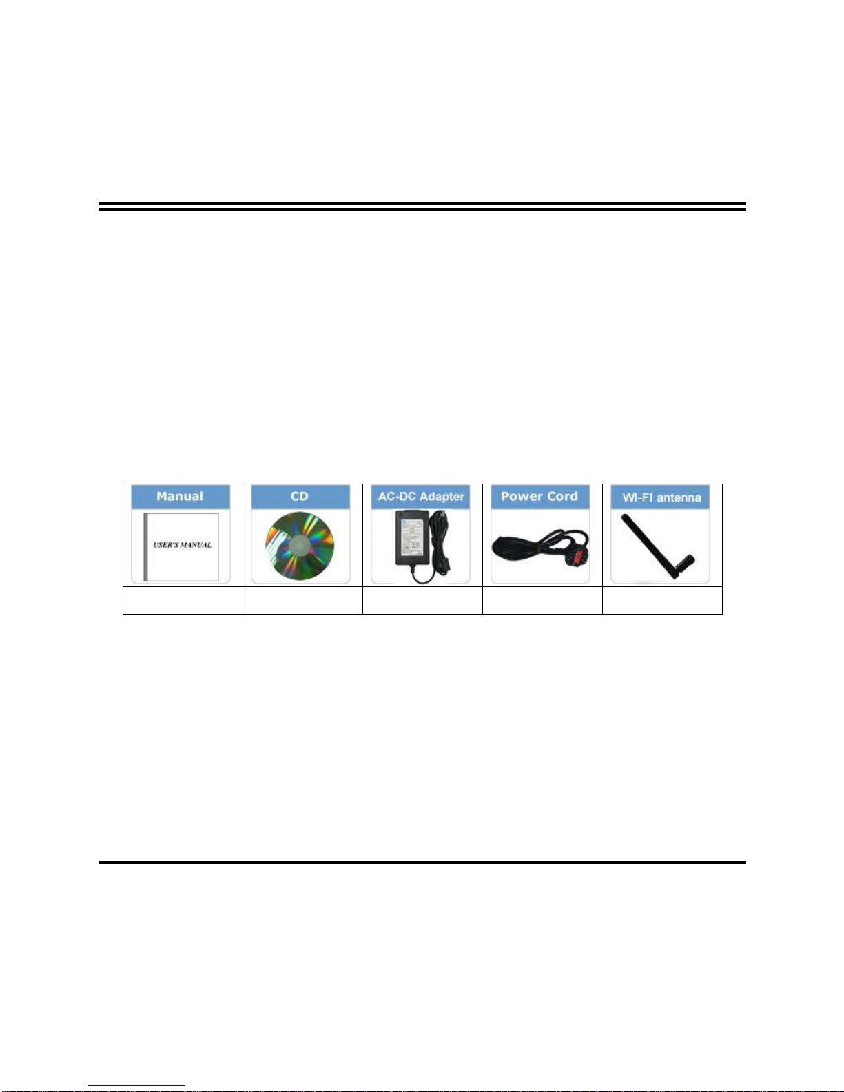
Package Contents
X2 X2 X1 X1
X2
Page 3
iii
Safety Instruction
Operate the product according to the correct installation steps and with great care to make sure
safety and comfort using experience. Please refer to the following safety instruction guide to avoid
danger of electric shock or fire. Abide by the previous safety instruction guide to use and maintain
the product and the hard disk to make sure of safe operating environment.
Please follow the instruction manual for operation guide.
The appropriate operating temperature ranges from 0 °C–50 °C.
The operation humidity for this product is 5% to 80% RH.
To avoid high temperature, please DO NOT overload the maximum power of the external power
supply while the system is consuming high voltage. Be aware of the maximum temperature
allowance of the power supply.
See to it that the product is not working near the water.
Always unplug power cable and other hardware cables from the system before cleaning.
Apply only dry cloth for cleansing the product.
Make sure that there is no heat source nearby when the product is working.
Make sure that the thermal louver of the product is not blocked.
Make sure to remove the power plug from the product when there is a thunder storm.
Please remove the power plug from the product when you are not going to use the product for a
long time.
Make sure to set up or use the product on a stable surface.
Make sure not to drop the product or strike it by any means.
Make sure not to move the product when the power is on.
Make sure not to step on the power cables and other cables or rest anything in them..
Please contact qualified technician for maintenance or repair.
Use only accessories and parts that are made by the qualified manufacturer.
Page 4
iv
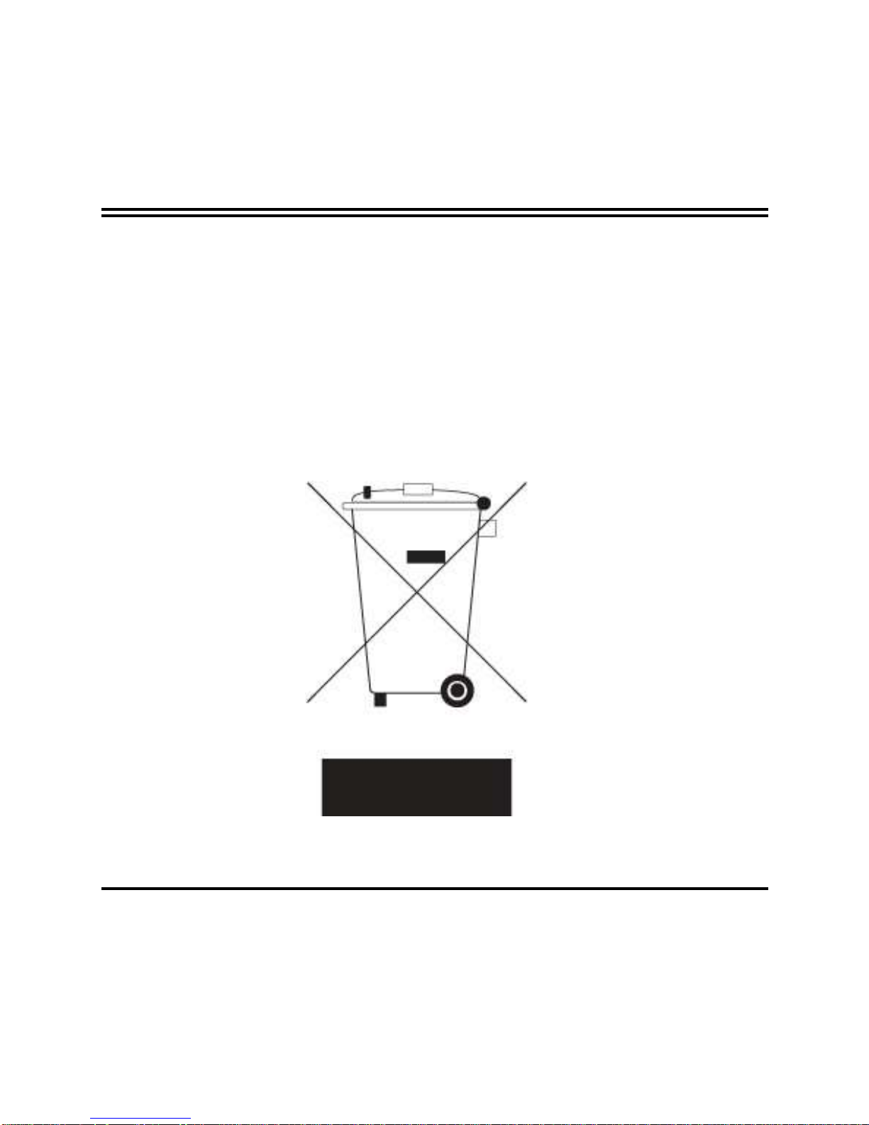
Environmental Protection Announcement
Do not dispose this electronic device into the trash while discarding. To minimize
pollution and ensure environment protection of mother earth, please recycle.
Page 5

v
USER’S NOTICE .......................................................................................................................ii
PACKAGE CONTENTS.............................................................................................................ii
SAFETY INSTRUCTION............................................................................................................iii
ENVIRONMENTAL PROTECTION ANNOUNCEMENT .........................................................iv
CHAPTER 1 PRODUCT FEATURES..................................................................................... 1
CHAPTER 2 SPECIFICATION ...............................................................................................3
CHAPTER 3 PRODUCT DIAGRAMS.....................................................................................4
CHAPTER 4 MAIN DIFFERENCES OF THE MODELS......................................................... 10
APPENDIX .................................................................................................................................11
TABLE OF CONTENT
Page 6

1
Chapter 1 Product Features
Thank you for purchasing the system, a new product developed, designed and
manufactured under leading technical power and consistent dedication to fine
workmanship.
This panel PC system is a powerful system with competitively advantage in:
Onboard Intel® Bay Trail series SoC processor, with low power consumption
never denies high performance
Onboard 4GB DDR3L 1333Mhz SO-DIMM
Support 1 * 2.5" SATAII (3Gb/s) HDD Device & 1* mSATA Device
Support dual gigabit LAN
Support VGA HD output
Support 802.11 b/g/n WiFi communication
Support multiple COM ports
IP65 Industrial protection level standard
Aluminum front panel structure; SECC steel foundation chassis
Support 9V~24V wide voltage range DC power-in
Compliance with EuP Standard
Page 7

2
The system has the following features besides other basic functions:
WiFi: the Mini PCI-E onboard socket in the board is integrated a with a WiFi
card(802.11 b/g/n) that can act as a mini wireless modem when external antennas
are connected. Different computers in the house can build wireless connections
through the Mini TOP system and take necessary data from it, thus reducing the
complexity in network establishment.
Giga LAN: The system is integrated with Gigabit LAN network controller with
ACPI management realizing efficient power management for the operating
system.
USB2.0: The system supports USB 2.0 function compatible for both USB 2.0
devices and USB 1.1 interface devices. Users can enjoy high speed data
transmission rate up to 480Mb/s. Users can also connect USB 2.0 storage device
to the system to create a data bank for storage of download movies.
USB3.0: Experience Fastest data transfers at 5Gb/s with USB3.0 the new latest
connectivity standard. Built connect easily with nextgeneration components and
peripherals, USB3.0 transfers data 10x faster and backward compatible with
previous USB2.0 components.
CPU Usage: The CPU Usage diagram shows a beautiful data curve that indicates
a pretty low CPU usage percentage for video playback of different formats. GPU
performances are excellent as well.
dB Value: The design of the system takes into consideration the needed quiet
operating environment in the living room and the average dB value is below 26
under normal operation to ensure the tranquility when you are absorbed in film
watching.
Page 8

3
Chapter 2 Specification
CPU
Intel® Bay Trail series SoC processor
Memory
Onboard 4GB DDR3L 1333MHz SO-DIMM
Dual LAN
Integrated with dual Intel i211AT PCI-E Gigabit LAN chips
Support Fast Ethernet LAN function of providing
10/100/1000Mbps Ethernet data transfer rate
HD Audio
Realtek ALC887 HD Audio Codec integrated
Storage
Support 1* 2.5’’ SATAII 3Gb/s device
Support 1 * M-SATA device
Bottom I/O
1 * Power Button
1* RS232 COM Port & 2* RS232/422/485 COM (Optional for
HPC-104BR series)
4* RS232 COM Port & 2* RS232/422/485 COM (Optional for
HPC-150BR series)
1 * VGA port
1* USB 3.0 port
3* USB 2.0 port
2* RJ-45 port(Gigabit LAN)
1* Line-Out port
1* DC-in power jack
Left & Right I/O
2 * Speaker (Optional for HPC-150BR series)
Power Supply
9V~24V DC-in power supply
Standard Accessories
1 * 60W AC-DC (12V/5A) Adapter
1 * Power cord
2* WIFI antenna
2* CD
2* Manual
Page 9

4
Chapter 3 Product Diagram
Notice: The following diagrams and photos in the manual serves as instruction purpose only and
may differ from actual product. Please refer to the product you purchase for actual specification.
Product Diagram for HPC-104BR Series:
Front View Appearance
Top View
WIFI Antenna
WIFI Antenna
Page 10

5
Bottom View
Product Dimension for HPC-104BR Series:
* Measure Unit: mm.
Power Button
RS232 COM Port
VGA Port
USB 2.0 Port
USB 3.0 Port
Line-Out Port
RJ-45 LAN Port
DC-In Power Jack
USB 2.0 Ports
RS232/422/485
COM Ports
Page 11

6
Product Diagram for HPC-150BR Series:
Front View
Top View
WIFI Antenna
WIFI Antenna
Page 12

7
Bottom View
Notice: The left side and the right side of HPC-104BR Series come without speakers.
Left View
Right View
Power Button
RS232 COM Port
VGA Port
USB 2.0 Port
USB 3.0 Port
RJ-45 LAN Port
DC-In Power Jack
Line-Out Port
RS232/422/485
COM Ports
USB 2.0 Ports
RS232 COM Ports
Speakers
Page 13

8
Product Dimension for HPC-150BR Series:
* Measure Unit: mm.
Page 14

9
Part & Name & Function Description:
Power Button
Press to turn on/off the system.
COM Port
Mainly for user to connect external MOD
EM or
other devices that supports
Serial Communications Interface.
VGA Port
T
o connect display device that support VGA
specification.
USB 2.0 Port
To
connect USB keyboard, mouse or other
devices compatible with USB 2.0 specification.
USB 3.0 Port
To
connect USB keyboard, mouse or other
devices compatible with USB specification.
USB
3.0 ports supports up to
5Gbps data transfer
rate.
RJ-45 LAN Port
This connector is standard RJ-45 LAN jack
for
Network connection.
Line-Out Connector
For us
er to connect external speaker,
earphones, etc to transfer system audio output.
9V~24V DC-In
Power Connector
For user to connect compatible power adapter
to this power jack after connecting connector
power cord to adapter.
Wi-Fi antenna
For better WI-FI reception.
Speaker
(Optional for
HPC-150BR
Series
ONLY)
Integrated speaker for audio output.
Page 15

10
Chapter 4 Main Differences of the Models
Model Name Panel
Size
Resolution Brightness Contrast
Ratio
Touch Panel Product Size
HPC-104BR-2930-4G
10.4’’ 800 x 600 230 cd/m2 500:1 Resistive screen 284 (L) * 230 (W) *37 (H)mm
HPC-104BRH-2930-4G
10.4’’ 800 x 600 400 cd/m2 700:1 Resistive screen 284 (L) * 230 (W) *37 (H)mm
HPC-150BR-2930-4G
15’’ 1024 x768 350 cd/m2 700:1 Resistive screen 376 (L) * 300 (W) *54 (H)mm
HPC-150BRH-2930-4G
15’’ 1024 x768 450 cd/m2 800:1 Resistive screen 376 (L) * 300 (W) *54 (H)mm
Page 16

11
Appendix
General Notices
European Union CE Marking and Compliance Notices
Products intended for sale within the European Union are marked with the Conformity European (CE)
Making, which indicates compliance with the applicable Directive and European standards and
amendments identified.
Shielded Cables Notice
All connections to other computing devices must be made using shielded cables to maintain
compliance with FCC regulations.
Peripheral Devices Notice
Only peripherals (input/out devices, terminals, printers, etc) certified to comply with Class B limits may
be attached to this equipment. Operation with non-certified peripherals is likely to result in interference
to radio and TV reception.
Wireless Related Information
Wireless Interoperability
Wireless LAN PCI Express Mini Card is designed to be interoperable with any wireless LAN product
that is based on Direct Sequence Spread Spectrum (DSSS), Complementary Code Keying (CKK),
and/or Orthogonal Frequency Division Multiplexing (OFDM) radio technology, and is compliant to:
The IEEE802.11a/b/g/n Standard on Wireless LANs was defined and approved by the Institute of
Electrical and Electronics Engineers.
The Wireless Fidelity (WiFi) certification as defined by the Wi-Fi Alliance.
Usage Environment and Your Health
Wireless LAN PCI Express Mini Card emits radio frequency electromagnetic energy like other radio
devices. However, the level of energy emitted is far much less than the electromagnetic energy emitted
by wireless devices like for example mobile phones.
Due to the fact that Wireless LAN PCI Express Mini Card operates within the guidelines found in radio
frequency safety standards and recommendations, we believe the integrated wireless cards are safe
Page 17

12
for use by consumers. These standards and recommendations reflect the consensus of the scientific
community and result from deliberations of panels and committees of scientists who continually review
and interpret the extensive research literature.
In some situation or environment, the use of Wireless LAN PCI Express
Mini Card may be restricted by the proprietor of the building or responsible representatives of the
organization. These situations may for example include:
Using the integrated wireless cards on board of airplanes, or in hospitals
In any other environment that the risk of interference to other devices and service are perceived or
identified to be harmful.
If you are uncertain of the policy that applies on the use of wireless devices in a specific organization
(e.g., airport or hospital), you are encouraged to ask for authorization to use Wireless LAN PCI Express
Mini Card prior to turning on the computer.
Electronic Emissions Notices
European Union Compliance Statement Class B Compliance
European Union – Compliance to the Electromagnetic Compatibility Directive
This product is in conformity with the protection requirements of EU Council Directive 2004/108/EC on
the approximation of the laws of the Member States relating to electromagnetic compatibility. We
cannot accept responsibility for any failure to satisfy the protection requirements resulting from a
non-recommended modification of the product, including the installation of option cards from other
manufacturers.
This product has been tested and found to comply with the limits Class B Information Technology
Equipment according to European Standard EN55022. The limits for Class B equipment were derived
for typical residential environments to provide reasonable protection against interference with licensed
communication devices.
Properly shielded and grounded cables and connectors must be used in order to reduce the potential
for causing interference to radio and TV communications and to other electrical or electronic
Page 18

13
equipment.
FCC Rules and Regulations-Part 15
This devices uses, generates and radiates radio frequency energy. The radio frequency energy
produced by this device is well below the maximum exposure allowed by the Federal Communications
Commission (FCC)
This device complies with the limits for the Class B digital device pursuant to Part 15 subject to the
following two conditions:
This device may not cause harmful interference.
This device must accept any interference received, including interference that may cause
undesired operation.
The FCC limits are designed to provide reasonable protection against harmful interference when the
equipment is installed and used in accordance with the instruction manual and operated in a
commercial environment. However, there is no guarantee that interference will not occur in a particular
commercial installation, or if operated in a residential area.
If harmful interference with radio or television reception occurs when the device is turned on, the user
must correct the situation at the user’s own expense. The user is encouraged to try one or more of the
following corrective measures:
Re-orient or relocate the receiving antenna.
Increase the separation between the equipment and receiver.
Connect the equipment into an outlet on a circuit different from that on which the receiver is
connected.
Consult the dealer or an experienced radio/TV technician for help.
CAUTION:
The Part 15 radio device operates on a non-interference basis with other devices
operating at this frequency. Any changes or modification to said product not expressly approved by
Intel could void the user’s authority to operate this device.
 Loading...