

JETWAY HBFHP792 Series, HBFHP792L Series, HBFHP792U Series, HBFHP792G Series, HBFHP792C Series User Manual
...Page 1

User’s Manual
NO. G03-NP792-F
Manual Revision: 1.0
Release Date:July 4, 2018
Page 2

i
Safety Precautions.............................................................................................................. ii
User’s Notice....................................................................................................................... iii
Package Contents............................................................................................................... iii
Environmental Protection Announcement ....................................................................... iii
Chapter 1 Introduction ..................................................................................................... 1
1-1 General Descriptions............................................................................................ 1
1-2 Specifications ....................................................................................................... 2
1-3 I/O Outlets ............................................................................................................. 3
1-4 Connector Pin Definition ...................................................................................... 5
Chapter 2 Hardware and Installation ............................................................................... 6
2-1 Dimensions and Outlines ..................................................................................... 6
2-2 To Open the Chassis ............................................................................................ 7
2-3 Jumper Settings.................................................................................................... 9
2-3-1 Motherboard Jumper Settings................................................................. 9
2-3-2 Daughter Board Jumper Settings............................................................ 11
2-4 Hardware Installation............................................................................................ 13
2-4-1 To install MSATA Card............................................................................. 13
2-4-2 To install Wireless LAN Card................................................................... 14
2-4-3 DIM Rail Installation ................................................................................. 17
Chapter 3 Introducing BIOS ............................................................................................. 18
3-1 Entering Setup ..................................................................................................... 18
3-2 BIOS Menu Screen............................................................................................... 19
3-3 Function Keys...................................................................................................... 19
3-4 Getting Help ......................................................................................................... 20
3-5 Menu Bars ............................................................................................................ 20
3-6 Main Menu............................................................................................................ 20
3-7 Advanced Menu ................................................................................................... 21
3-8 Chipset Menu ....................................................................................................... 28
3-9 Security Menu ...................................................................................................... 39
3-10 Boot Menu............................................................................................................ 30
3-11 Save & Exit Menu................................................................................................. 31
APPENDIX ........................................................................................................................... 32
TABLE OF CONTENT
Page 3

ii
Safety Precautions
Operate the product according to the correct installation steps and with great care to make sure
safety and comfort using experience. Please refer to the following safety instruction guide to avoid
danger of electric shock or fire. Abide by the previous safety instruction guide to use and maintain
the product and the hard disk to make sure of safe operating environment.
Please follow the instruction manual for operation guide.
The appropriate operating temperature ranges from 0 °C–50 °C.
The operation humidity for this product is 5% to 80% RH.
To avoid high temperature, please DO NOT overload the maximum power of the external power
supply while the system is consuming high voltage. Be aware of the maximum temperature
allowance of the power supply.
See to it that the product is not working near the water.
Always unplug power cable and other hardware cables from the system before cleaning.
Apply only dry cloth for cleansing the product.
Make sure that there is no heat source nearby when the product is working.
Make sure that the thermal louver of the product is not blocked.
Make sure to remove the power plug from the product when there is a thunder storm.
Please remove the power plug from the product when you are not going to use the product for a
long time.
Make sure to set up or use the product on a stable surface.
Make sure not to drop the product or strike it by any means.
Make sure not to move the product when the power is on.
Make sure not to step on the power cables and other cables or rest anything in them..
Be sure to ground yourself to prevent static charge when installing any internal components. Use a
grounding wrist strap and place all electronic components in any static-shielded devices. Most
electronic components are sensitive to static electrical charge.
Disconnect the power cord from the Panel PC unit prior to any installation. Be sure both the
system and all external devices are turned off. Sudden surge of power could ruin sensitive
components. Make sure the Panel PC unit is properly grounded. unit
Do not open the system’s back cover. If opening the cover for maintenance is a must, only a
trained technician is allowed to do so. Integrated circuits on computer boards are sensitive to static
electricity. To avoid damaging chips from electrostatic discharge, observe the following
precautions:
Before handling a board or integrated circuit, touch an unpainted portion of the system
unit chassis for a few seconds. This will help to discharge any static electricity on human
body.
When handling boards and components, wear a grounding wrist strap available from
most electronic component stores.
Please contact qualified technician for maintenance or repair.
Use only accessories and parts that are made by the qualified manufacturer.
Page 4

iii
User’s Notice
Copyright of this manual belongs to the manufacturer. No part of this manual, including the products
and software described in it may be reproduced, transmitted or translated into any language in any
form or by any means without written permission of the manufacturer.
This manual contains all information required for the utilization of this product to meet the user’s
requirements. But it will change, correct at any time without notice. Manufacturer provides this manual
“as is” without warranty of any kind, and will not be liable for any indirect, special, incidental or
consequential damages (including damages for loss of profit, loss of business, loss of use of data,
interruption of business and the like).
Products and corporate names appearing in this manual may or may not be registered trademarks or
copyrights of their respective companies, and they are used only for identification or explanation and to
the owner’s benefit, without intent to infringe.
Package Contents
▶
User’s Manual
▶
DVD for System Utilities
▶
Power Core Cable
▶
Power Adapter
▶
Wi-Fi Antenna
▶
DIN Rail Rack (Optional)
Environmental Protection Announcement
Do not dispose this electronic device into the trash while discarding. To minimize
pollution and ensure environment protection of mother earth, please recycle.
Page 5

1
Chapter 1
Introduction
1-1 General Descriptions
Thank you for purchasing the system, a new product developed, designed and
manufactured under leading technical power and consistent dedication to fine
workmanship.
The HBFHP792X series is a rugged fanless automation system, with flexibility to
different configuration through optional expansion solutions, all customized to
meet different demands from our customers.
The system has the following features besides other basic functions:
WiFi: the Mini PCI-E onboard socket in the board is integrated a with a WiFi
card(802.11 b/g/n) that can act as a mini wireless modem when external
antennas are connected. Different computers in the house can build wireless
connections through the Mini TOP system and take necessary data from it, thus
reducing the complexity in network establishment.
Giga LAN: The system is integrated with Gigabit LAN network controller with
ACPI management realizing efficient power management for the operating
system.
USB3.0: Experience Fastest data transfers at 5Gb/s with USB3.0 the new latest
connectivity standard. Built connect easily with next-generation components and
peripherals, USB3.0 transfers data 10x faster and backward compatible with
previous USB2.0 components.
CPU Usage: The CPU Usage diagram shows a beautiful data curve that
indicates a pretty low CPU usage percentage for video playback of different
formats. GPU performances are excellent as well.
dB Value: The design of the system takes into consideration the needed quiet
operating environment in the living room and the average dB value is below 26
under normal operation to ensure the tranquility when you are absorbed in film
watching.
Page 6

2
1-2 Specifications
Main CPU Board
CPU
Intel® Bay Trail series SoC processor, depending on different solutions.
System Memory
Onboard 2GB DDR3L 1333MHz SO-DIMM
Network
2* Intel GbE (MB/Intel i210IT)
BIOS
AMI 64Mb Flash ROM
Storage
Onboard 1* full-size MSATA slot (for MSATA card)
Expansion Slot
Onboard 1* M.2-2230 slot (for WiFi expansion)
I/O System
Standard I/O of the Motherboard
1* Lockable 12V DC-in Power Jack
1* USB 2.0
1* USB 3.0
1* VGA
2* RJ-45 for Gigabit Ethernet
1* Power Button
1* Power LED (Green)+ 1* HDD LED (Red)
Power Source
FSP 90~240V AC to DC Power Adapter/DC12V-3.3A-40W/LV6
Expansion I/O of Daughter board
*Expansion IO l varies from different daughter board solutions. Please refer to
Page-3/4 for more specifc specification.
Page 7
3
1-3 I/O Outlets
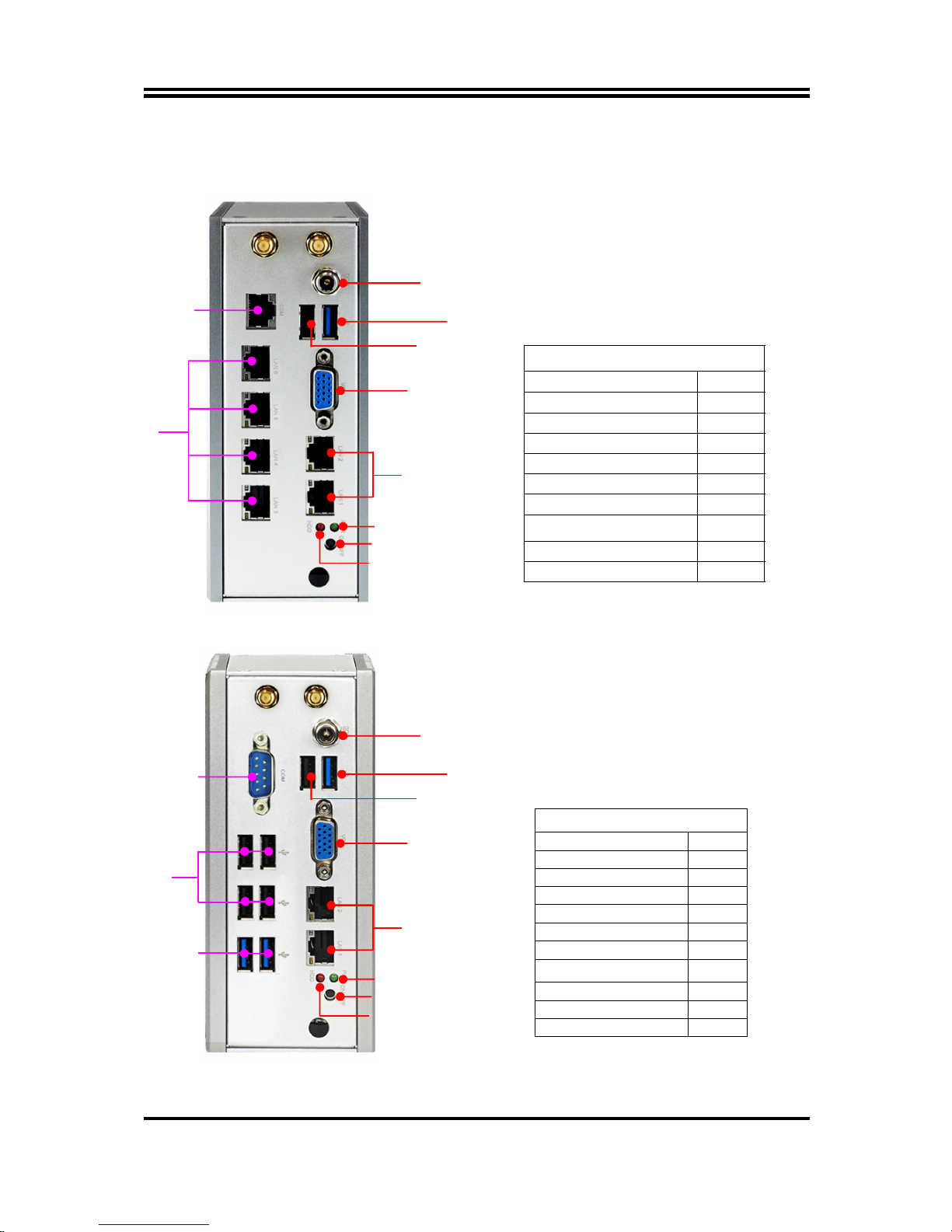
For HBFHP792L Series:
HBFHP792L Series
Standard IO Q’ty
DC-in 1
USB2.0 1
USB3.0 1
VGA 1
RJ-45 LAN 2
Power Switch 1
Expansion IO Q’ty
RJ-45 LAN 4
RJ-45 RS232 COM 1
For HBFHP792U Series:
HBFHP792U Series
Standard IO Q’ty
DC-in 1
USB2.0 1
USB3.0 1
VGA 1
RJ-45 LAN 2
Power Switch 1
Expansion IO Q’ty
RS232 COM 1
USB2.0 4
USB3.0 2
DC-IN
USB 3.0
USB 2.0
VGA
RJ-45 LAN
RJ-45 Type
RS232 COM
RJ-45
LAN
Power On/Off
Power LED
HDD LED
DC-IN
USB 3.0
USB 2.0
VGA
RJ-45 LAN
RS232
COM
Power On/Off
Power LED
HDD LED
USB 2.0
USB 3.0
Page 8
4
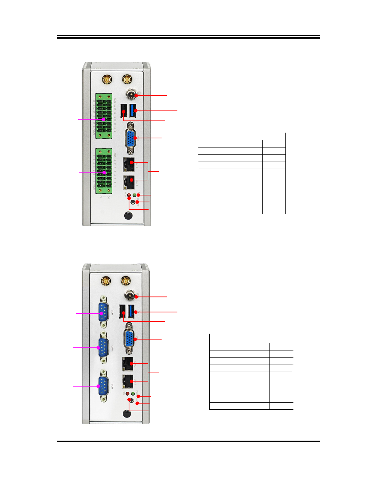
For HBFHP792G Series:
HBFHP792G Series
Standard IO Q’ty
DC-in 1
USB2.0 1
USB3.0 1
VGA 1
RJ-45 LAN 2
Power Switch 1
Expansion IO Q’ty
GPIO Block
(16-pin in+16-pin out)
2
For HBFHP792C Series:
HBFHP792L Series
Standard IO Q’ty
DC-in 1
USB2.0 1
USB3.0 1
VGA 1
RJ-45 LAN 2
Power Switch 1
Expansion IO Q’ty
RS232 COM 3
DC-IN
USB 3.0
USB 2.0
VGA
RJ-45 LAN
GPIO1
Power On/Off
Power LED
HDD LED
GPIO2
DC-IN
USB 3.0
USB 2.0
VGA
RJ-45 LAN
Power On/Off
Power LED
HDD LED
RS232
COM
RS232
COM
RS232
COM
Page 9
5
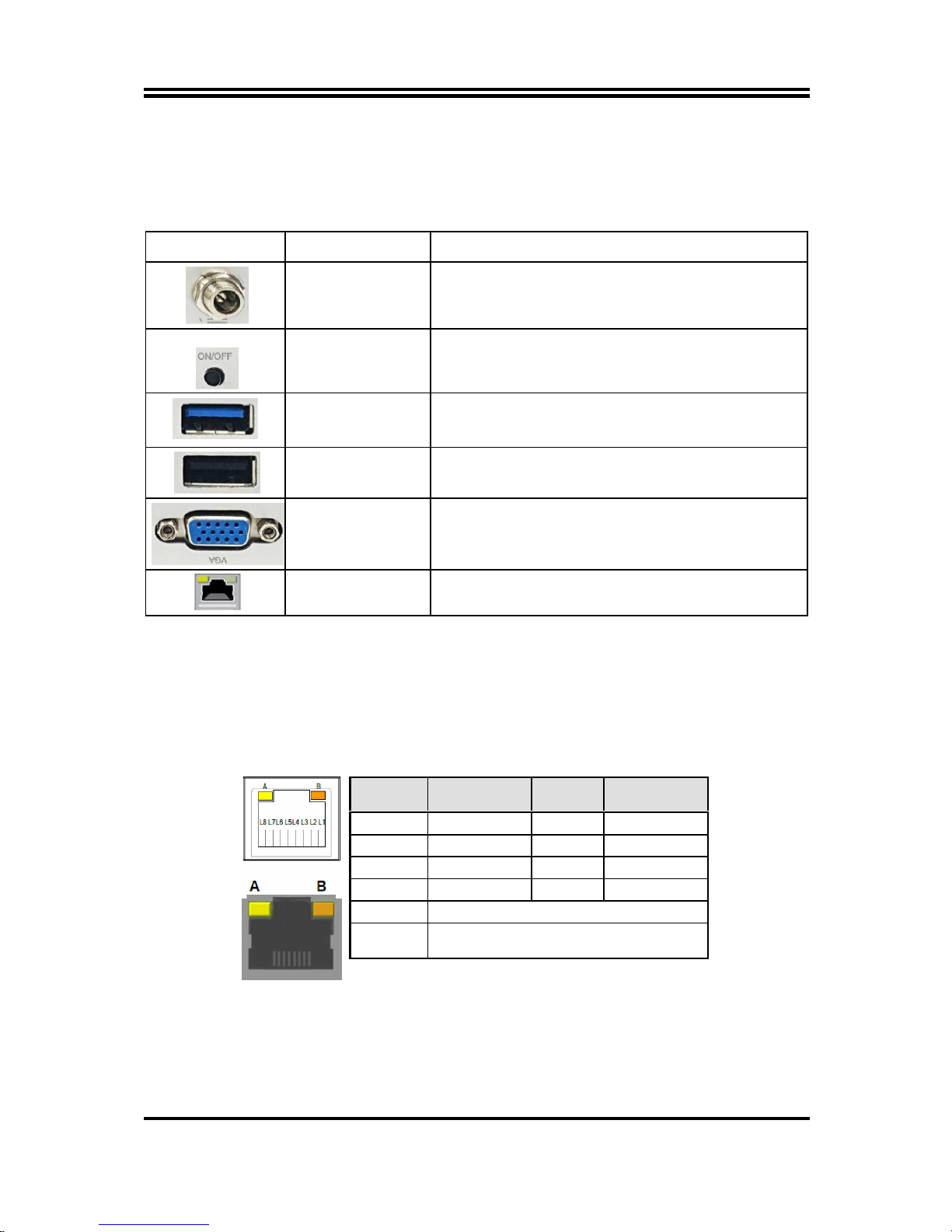
1-4 Connector Pin Definition
(1) Motherboard Connector Function
The system comes with NP792-D2 as motherboard, which including the following
basic I/O:
Icon Name Function
DC-in Power Jack
Connector
For user to connect compatible power adapter to provide
power supply for the system.
Power Button
Press to turn on/off the system.
USB 3.0 Port
To
connect USB keyboard, mouse or other devices
compatible with USB specification. USB 3.0 ports
supports up to 5Gbps data transfer rate.
USB 2.0 Port
To connect USB keyboard, mouse o
r other devices
compatible with USB specification.
VGA Port
To connect display device that support VGA specification.
RJ-45 LAN Port
This connector is standard RJ-45 LAN jack
for Network
connection.
(2) I/O Connectors Pin Definition
RJ-45 Ethernet Connector
Ethernet connection can be established by plugging one end of the Ethernet cable
into this RJ-45 connector and the other end (phone jack) to a 1000/100/10-Base-T
hub.
The pin assignment for RJ-45 Ethernet LAN connectors are listed as follows:
Pin Definition Pin Definition
L1 MDI0+ L5 MDI2+
L2 MDI0- L6 MDI2-
L3 MDI1+ L7 MDI3+
L4 MDI1- L8 MDI3-
A
Active LED (Yellow)
B
100 LAN LED (Green) / 1000 LAN LED
(Orange)
Page 10
6
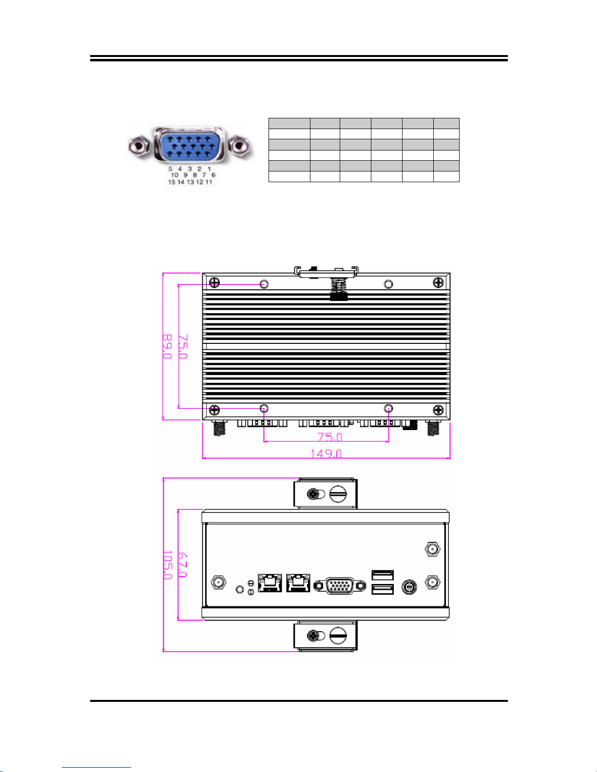
VGA Port Connector
The pin assignment for VGA port is listed as follows:
Pin No. 1 2 3 4 5
Definition
R G B NC GND
Pin No. 6 7 8 9 10
Definition
R-GND G-GND B-GND +5V GND
Pin No. 11 12 13 14 15
Definition NC SDA H-SYN V-SYN SCL
Chapter 2
Hardware and Installation
2-1 Dimension and Outlines
* Measure Unit: mm.
Page 11
7
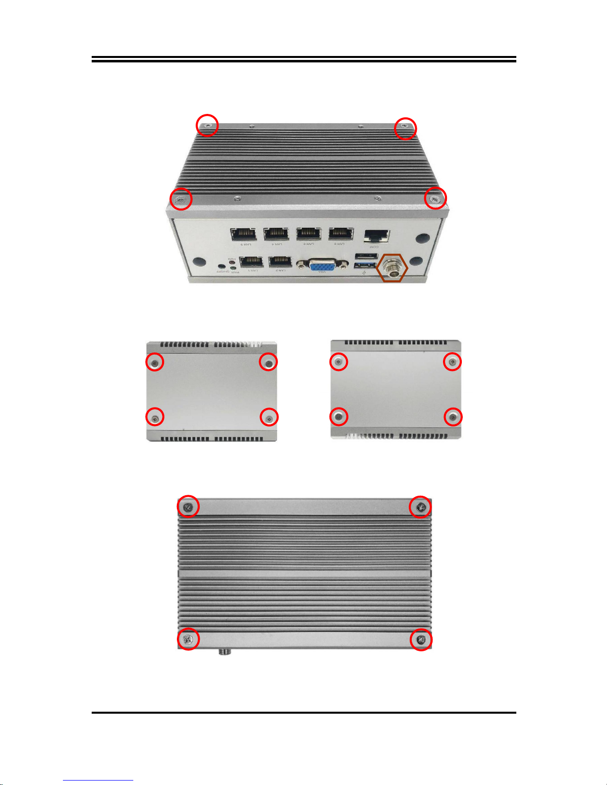
2-2 To Open the Chassis
1. Place the system on a flat platform upon a cushion. Remove the 4*screws in the marked
spots of system heatsink with a screwdriver. Also please remove the hexagon screw nut
that lock the DC-in power jack.
2. Remove the 4* screws that lock the side
metal plate.
3. Remove the other 4*screws on the
opposite side of the system that lock the
metal panel.
4. With the top heatsink (Step-1) still attached, turn over the system and remove the 4*screws
in the marked spots on the base heat sink.
Page 12
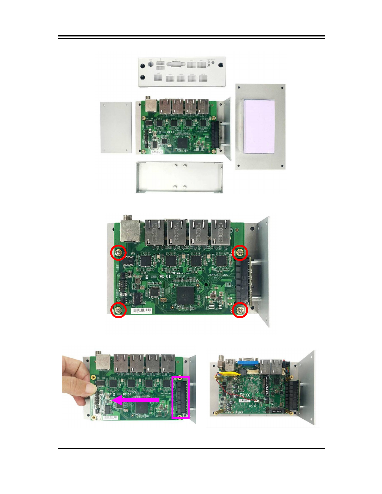
8
5. Dissemble the front/back panels, side metal plate, and top heat sink from the system.
6. Remove the 4* screws in the marked spots that lock compatible expansion card.
7. Disconnect the expansion card from the
PCIE riser card.
8. The internal view of the motherboard of
the system for further installation.
Page 13

9
2-3 Jumper Settings
Jumper is a small component consisting of jumper clip and jumper pins. Install
jumper clip on 2 jumper pins to close the pins. And remove jumper clip from 2
jumper pins to open the pins. Diagram 2-1 illustrates how to set up a jumper.
2-3-1 Motherboard Jumper Settings
The system comes with NP792 series IPC board as the motherboard, which has
the following basic jumper settings:
(1) JAT_ATX (3-pin): AT/ATX Mode Function Select
3
3
1
1
JAT_ATX→ATX/AT Mode Select
1-2 Close: ATX Mode Selected(Default);
2-3 Close: AT ModSelected.
*ATX Mode Selected: Press power button to power on after power input ready;
AT Mode Selected: Directly power on as power input ready.
(2) JP1 (3-pin): M2E (M.2 PCIe) Slot VCC Select
3
3
1
1
JP1→M2E Slot VCC Select
1-2 Close: M2E Slot=3.3V;
2-3 Close: M2E Slot=3.3VSB.
JAT_ATX
JP1
Page 14

10
(3) Pin (1-2) of JPCLR(4-pin): Clear CMOS Settings
Pin1
2
Pin(1-2) of JPCLR→Clear CMOS Settings
1-2 Open: Normal;
1-2 Closed: Clear CMOS(One Touch).
5
6
Pin1
2
6
5
(4) Pin (5-6) of JPCLR(4-pin): TXE Function Select
Pin1
2
Pin(5-6) of JPCLR→TXE Function Select
1-2 Open: Enable TXE;
1-2 Closed: Disable TXE.
5
6
Pin1
2
6
5
JPCLR
JPCLR
Page 15

11
2-3-2 Daughter Board Jumper Settings
The system comes with different expansion solutions, which are realized
though different daughter boards. Each has different jumper settings, as the
following shows:
JIOP4INLANG Series
JPCOM1 COM1 RJ-45 COM Port RI Selection
2-4 RS232 RI (Default)
3-4 +5V
6-4 +12V
JPCOM2 COM2 Header RI Selection
2-4 RS232 RI (Default)
3-4 +5V
6-4 +12V
JIOP32GPIO Series
JP_GPIO2 GPIO2 Block VCC Select
1-3 5V
3-5 3.3V
2-4 5VSB
4-6 3VSB
JP_GPIO1 GPIO2 Block VCC Select
1-2 5V
3-4 3.3V
JP2
JP1
COM1
COM2
JP_GPIO1
JP_GPIO2
GPIO1
GPIO2
Page 16

12
JIOP3COM Series
JPCOM1 COM1 Port RI Selection
2-4 RS232 RI (Default)
3-4 +5V
6-4 +12V
JPCOM2 COM2 Port RI Selection
2-4 RS232 RI (Default)
3-4 +5V
6-4 +12V
JPCOM3 COM3 Port RI Selection
2-4 RS232 RI (Default)
3-4 +5V
6-4 +12V
JIO2U34U21C Series
JPCOM1 COM1 RJ-45 COM Port RI Selection
2-4 RS232 RI (Default)
3-4 +5V
6-4 +12V
JPCOM2 COM2 Header RI Selection
2-4 RS232 RI (Default)
3-4 +5V
6-4 +12V
COM1
COM2
COM3
JPCOM1
JPCOM2
COM1
JPCOM1
COM2
COM2
JPCOM3
Page 17

13
2-4 Hardware Installation
Remove the screws that lock the back cover to the system from the back side before
hardware installation procedures (refer to 2-2).
2-4-1 To Install MSATA Card
1. Locate the full-size MSATA slot on the
board.
2. Remove the marked screw and use it to
lock MSATA card to the slot in later
installation.
3. Insert the gold-figure side of the
compatible MSATA card into the slot at a
30 degree angle and press down.
4. Lock the card to the board by tightening
up the screw to the marked spot.
Page 18

14
2-4-2 To Install Wireless LAN Card
Remove the screws that lock the cover to the system before installing Wi-Fi card
procedures (refer to 2-2).
Please refer to the following instructions for the installation of the wireless LAN card
into M.2 PCIe slot.
1. Locate the M.2. PCIe slot on the board. 2. Remove the marked screw and use it to
lock compatible Wi-Fi card to M.2. PCIe
slot in later installation.
3. Insert the gold-figure side of compatible
card into M.2. PCIe slot and press down.
See to it that the golden-figure side is
fully inserted into the slot.
4. Lock the card to the board by tightening
up the screw to the marked spot.
Page 19

15
5. Find the antenna wires from the
accessories package.
6. In the case that the metal hats on the end
of the antenna wires are sealed by
acetate tape, tear it off to find metal hats
of Wi-Fi antenna wire.
7. Press the metal hats of the antenna string
end to the antenna slots on the card as
showed.
8. There are 3 reserved holes in the front
panel for WiFi antenna installation.
Remove the dust plug from the spot you
choose to install antenna head.
9. Internal View: Put the above metal gasket into the antenna head at first, and then push
this antenna head into the back side of the rear panel.
Page 20

16
10. External View: Put the metal ring into the antenna head, and then lock the antenna
head to the front side of the rear panel the above hexagonal bolt.
11. The IO panel with antenna head installed. 12. Connect the external Wi-Fi receiver
antenna to the antenna head on the
panel.
Page 21

17
2-4-3 DIN Rail Installation
The system supports DIN Rail & VESA mount. Please find respective racks from
optional assesories package, and refer to the following for installation guide:
1. There are 4* screw holes on the side of
the system reserved for DIN Rail
installation. The 4* screw holes on the
heat sink are reserved for VESA mount
installation.
2. Find the DIN rail rack and lock it to the
system, as the photo shows.
3. Adjust the rack with system installed to
position of the sliding track you wish to
installed.
4. Match corresponding screw holes from
the rack and the track and lock the rack to
the sliding track with screws, as the photo
shows.
Page 22

18
Chapter 3
Introducing BIOS
Notice!
The BIOS options in this manual are for reference only. Different
configurations may lead to difference in BIOS screen and BIOS
screens in manuals are usually the first BIOS version when the board
is released and may be different from your purchased motherboard.
Users are welcome to download the latest BIOS version form our
official website.
The BIOS is a program located on a Flash Memory on the motherboard. This program
is a bridge between motherboard and operating system. When you start the computer,
the BIOS program will gain control. The BIOS first operates an auto-diagnostic test
called POST (power on self test) for all the necessary hardware, it detects the entire
hardware device and configures the parameters of the hardware synchronization.
Only when these tasks are completed done it gives up control of the computer to
operating system (OS). Since the BIOS is the only channel for hardware and software
to communicate, it is the key factor for system stability, and in ensuring that your
system performance as its best.
3-1 Entering Setup
Power on the computer and by pressing <Del> immediately allows you to enter Setup.
If the message disappears before your respond and you still wish to enter Setup,
restart the system to try again by turning it OFF then ON or pressing the “RESET”
button on the system case. You may also restart by simultaneously pressing <Ctrl>,
<Alt> and <Delete> keys. If you do not press the keys at the correct time and the
system does not boot, an error message will be displayed and you will again be asked
to
Press
<Del>
to enter Setup; press <
F7
> for Pop Menu.
Page 23

19
3-2 BIOS Menu Screen
The following diagram show a general BIOS menu screen:
BIOS Menu Screen
3-3 Function Keys
In the above BIOS Setup main menu of, you can see several options. We will explain
these options step by step in the following pages of this chapter, but let us first see a
short description of the function keys you may use here:
Press (left, right) to select screen;
Press (up, down) to choose, in the main menu, the option you want to confirm
or to modify.
Press
<Enter>
to select.
Press
<+>/<–>
keys when you want to modify the BIOS parameters for the active
option.
[F1]:
General help.
[F2]:
Previous value.
[F3]:
Optimized defaults.
[F4]:
Save & Exit.
Press
<Esc>
to quit the BIOS Setup.
Menu Bar
Menu Items
Current Setting Value
Function Keys
General Help Items
Page 24

20
3-4 Getting Help
Main Menu
The on-line description of the highlighted setup function is displayed at the top right
corner the screen.
Status Page Setup Menu/Option Page Setup Menu
Press [F1] to pop up a small help window that describes the appropriate keys to use
and the possible selections for the highlighted item. To exit the Help Window, press
<
Esc
>.
3-5 Menu Bars
There are six menu bars on top of BIOS screen:
Main To change system basic configuration
Advanced To change system advanced configuration
Chipset To change chipset configuration
Security Password settings
Boot To change boot settings
Save & Exit Save setting, loading and exit options.
User can press the right or left arrow key on the keyboard to switch from menu bar.
The selected one is highlighted.
3-6 Main Menu
Main menu screen includes some basic system information. Highlight the item and
then use the <+> or <-> and numerical keyboard keys to select the value you want in
each item.
System Date
Set the date. Please use [Tab] to switch between data elements.
System Time
Set the time. Please use [Tab] to switch between time elements.
Page 25

21
3-7 Advanced Menu
OS Selection
The optional settings: [Android]; [Windows 8.X]; [Windows 7].
*Note: User needs to go to this item to select OS before installing OS.
If Windows Embedded standard 8, please select [Windows 8x] and set “USB 3.0
Support” as [Disabled], “USB 2.0 Support” as [Enabled] (refer to Page 32).
ACPI Settings
Press [Enter] to make settings for the following sub-item:
ACPI Settings
ACPI Sleep State
Use this item to select the highest ACPI sleep state the system will enter when the
suspend button is pressed.
The optional settings are: [Suspend Disabled]; [S3 (Suspend to RAM)].
Wake-up Function Settings
Press [Enter] to make settings for the following sub-items:
Wake-up System with Fixed Time
Use this item to enable or disable system wake-up on alarm event.
The optional settings: [Disabled]; [Enabled].
When set as [Enabled], system will wake on the hour/min/sec specified.
Wake-up System with Dynamic Time
Use this item to enable or disable system wake-up on alarm event.
The optional settings: [Disabled]; [Enabled].
When set as [Enabled], system will wake on the current time + increased
minute(s).
The settings range is from [1] ~ [60] minute(s).
USB S3/S4 Wake-up
Use this item to enable or disable USB S3/S4 Wake-up.
The optional settings: [Disabled]; [Enabled].
Page 26

22
*This item is only supported when ‘ERP Support’ is set as [Disabled].
Super I/O Configuration
Press [Enter] to make settings for the following sub-items:
Super IO Configuration
ERP Support
The optional settings: [Disabled]; [Auto].
This item should be set as [Disabled] if you wish to have all active wake-up
functions.
WatchDog Reset Timer
This item support WDT reset function.
The optional settings: [Disabled]; [Enabled].
Use this item to enable or disable WatchDog Timer Control. When set as
[Enabled], the following sub-items shall appear:
WatchDog Reset Timer Value
User can set a value in the range of [10] to [255] seconds or in the range of [1] to
[255] minutes.
WatchDog Reset Timer Unit
The optional settings are: [Sec.]; [Min.].
WatchDog Wake-up Timer in ERP
This item support WDT wake-up while ‘ERP Support’ is set as [Auto].
The optional settings are: [Enabled]; [Disabled].
When set as [Enabled], the following sub-items shall appear:
WatchDog Timer Value in ERP
User can set a value in the range of [10] to [4095] seconds when‘WatchDog
Timer Unit in ERP’ set as [Sec.], or in the range of [1] to [4095] minutes when
‘WatchDog Timer Unit in ERP’ set as [Min.].
WatchDog Timer Unit in ERP
The optional settings are: [Sec.]; [Min.].
ATX Power Emulate AT Power
This item displays current Emulate AT Power Status, motherboard power On/Off
control by power supply. User needs to select ‘AT or ATX Mode’ on MB jumper at
first (refer to Page 8~9, Jumper AT_MODE for ATX Mode & AT Mode Select).
PC Health Status
Press [Enter] to view current hardware health status.
Addon Card Serial Port Configuration
Press [Enter] to make settings for the following sub-items:
Addon Card Serial Port Configuration
▶
Serial Port 1/2 Configuration
Press [Enter] to make settings for the following items:
Serial Port
Use this item to enable or disable serial port (COM).
The optional settings are: [Disabled]; [Enabled].
When set as [Enabled], the following sub-items shall appear:
Change Settings
Use this item to select an optimal setting for super IO device. Changing setting
may conflict with system resources.
Page 27

23
Transmission Mode Select
Use this item to select transmission mode.
The optional settings: [RS422]; [RS232]; [RS485].
Mode Speed Select
Use this item to select transmission mode speed.
The optional settings: [RS232/RS422/RS485=250Kbps]; [RS232=1Mbps,
RS422/RS485=10Mpbs].
OS Select for Serial Port
Serial port supports for Windows or Linux.
The optional settings are: [Windows]; [LINUX].
Shutdown Temperature Configuration
Press [Enter] to set shut down temperature for the system.
Shutdown Temperature
Use this item to select system shutdown temperature.
The optional settings are: [Disabled]; [70oC/158oF]; [75oC/167oF]; [80oC/176oF];
[85oC/185oF].
Serial Port Console Redirection
COM1
Console Redirection
The optional settings: [Disabled]; [Enabled]. When set as [Enabled], the following
sub-items shall appear:
Console Redirection Settings
The settings specify how the host computer and the remote computer (which the
user is using) will exchange data. Both computers should have the same or
compatible settings.
Press [Enter] to make settings for the following items:
Terminal Type
The optional settings: [VT100]; [VT100+]; [VT-UTF8]; [ANSI].
Emulation: [ANSI]: Extended ASCII char set; [VT100]: ASCII char set; [VT100+]:
Extends VT100 to support color, function keys, etc.; [VT-UTF8]: Uses UTF8
encoding to map Unicode chars onto 1 or more bytes.
Bits per second
Use this item to select serial port transmission speed. The speed must be
matched on the other side. Long or noisy lines may require lower speeds.
The optional settings: [9600]; [19200]; [38400]; [57600]; [115200].
Data Bits
The optional settings: [7]; [8].
Parity
A parity bit can be sent with the data bits to detect some transmission errors.
The optional settings: [None]; [Even]; [Odd]; [Mark]; [Space].
[Even]: parity bit is 0 if the num of 1’s in the data bits is even; [Odd]: parity bit is 0
if num of 1’s in the data bits is odd; [Mark]: parity bit is always 1; [Space]: Parity
bit is always 0; [Mark] and [Space] Parity do not allow for error detection.
Stop Bits
Stop bits indicate the end of a serial data packet. (A start bit indicates the
beginning). The standard setting is 1 stop bit. Communication with slow devices
may require more than 1 stop bit.
Page 28

24
The optional settings: [1]; [2].
Flow Control
Flow control can prevent data loss from buffer overflow. When sending data, if
the receiving buffers are full, a “stop” signal can be sent to stop the data flow.
Once the buffers are empty, a “start” signal can be sent to re-start the flow.
Hardware flow control uses two wires to send start/stop signals.
The optional settings: [None]; [Hardware RTS/CTS].
VT-UTF8 Combo Key Support
Use this item to enable VT-UTF8 Combination Key Support for ANSI/VT100
terminals.
The optional settings: [Disabled]; [Enabled].
Recorder Mode
With this mode enable only text will be sent. This is to capture Terminal data.
The optional settings: [Disabled]; [Enabled].
Resolution 100x31
Use this item to enable or disable extended terminal resolution.
The optional settings: [Disabled]; [Enabled].
Legacy OS Redirection Resolution
On Legacy OS, the Number of Rows and Columns supported redirection.
The optional settings: [80x24]; [80x25].
Putty KeyPad
Use this item to select FunctionKey and KeyPad on Putty.
The optional settings: [VT100]; [Linux]; [XTERMR6]; [SCO]; [ESCN]; [VT400].
Redirection After BIOS POST
The optional settings are: [Always Enable]; [BootLoader].
Whet [Bootloader] is selected, then Lagacy Console Redirection is disabled
before booting to legacy OS. When [Always Enable] is selected, then Legacy
Console is enabled for legacy OS. Default setting for this option is set to [Always
Enable].
Legacy Console Redirection
Legacy Console Redirection Settings
Press [Enter] to make settings for the following item:
Legacy Serial Redirection Port
For user to select a COM port to display redirection of legacy OS and Legacy
OPROM messages.
The optional setting is: [COM1].
Serial Port for Out-of-Band Management/
Windows Emergency Management Services (EMS)
Console Redirection
The optional settings: [Disabled]; [Enabled]. When set as [Enabled], the following
sub-items shall appear:
Console Redirection Settings
The settings specify how the host computer and the remote computer (which the
user is using) will exchange data. Both computers should have the same or
compatible settings.
Press [Enter] to make settings for the following items:
Page 29

25
Out-of-Band Mgmt Port
The optional setting is: [COM1].
Terminal Type
The optional settings: [VT100]; [VT100+]; [VT-UTF8]; [ANSI].
[VT-UTF8] is the preferred terminal type for out-of-band management. The next
best choice is [VT100+] and them [VT100]. See above, in Console Redirection
Settings page, for more help with Terminal Type/Emulation.
Bits per second
Use this item to select serial port transmission speed. The speed must be
matched on the other side. Long or noisy lines may require lower speeds.
The optional settings: [9600]; [19200]; [57600]; [115200].
Flow Control
Flow control can prevent data loss from buffer overflow. When sending data, if
the receiving buffers are full, a “stop” signal can be sent to stop the data flow.
Once the buffers are empty, a “start” signal can be sent to re-start the flow.
Hardware flow control uses two wires to send start/stop signals.
The optional settings: [None]; [Hardware RTS/CTS]; [Software Xon/Xoff].
Data Bits
The default setting is: [8].
*This item may or may not show up, depending on different configuration.
Parity
The default setting is: [None].
*This item may or may not show up, depending on different configuration.
Stop Bits
The default setting is: [1].
*This item may or may not show up, depending on different configuration.
CPU Configuration
Press [Enter] to view current CPU configuration and make settings for the
following sub-items:
Limit CPUID Maximum
The optional settings: [Disabled]; [Enabled].
This item should be set as [Disabled] for Windows XP.
Execute Disable Bit
The optional settings: [Disabled]; [Enabled].
Hardware Prefetcher
The optional settings are: [Disabled]; [Enabled].
Use this item to turn on/off the Mid Level Cache (L2) streamer prefetcher.
Adjacent Cache Line Prefetch
The optional settings are: [Disabled]; [Enabled].
Use this item to turn on/off prefetching of adjacent cache lines.
Intel Virtualization Technology
The optional settings: [Enabled]; [Disabled].
When set as [Enabled], a VMM can utilize the additional hardware capabilities
provided by Vanderpool Technology.
EIST
The optional settings: [Disabled]; [Enabled].
Use this item to enable or disable Intel SpeedStep.
Page 30

26
SATA Configuration
Press [Enter] to make settings for the following sub-items:
SATA Configuration
SATA Port
The optional settings: [Disabled]; [Enabled].
When set as [Enabled], the following sub-items shall appear:
SATA Mode
The optional settings are: [IDE Mode]; [AHCI Mode].
SATA Speed Support
The item is for user to set the maximum speed the SATA controller can support.
The optional settings are: [Gen1]; [Gen2].
mSATA
User this item to enable or disable MSATA device connected to MSATA.
The optional settings are: [Enabled]; [Disabled].
Network Stack Configuration
Press [Enter] to go to ‘Network Stack’ screen to make further settings.
Network Stack
Use this item enable or disable UEFI network stack.
The optional settings are: [Enabled]; [Disabled].
When set as [Enabled], the following sub-items shall appear:
Ipv4 PXE Support
The optional settings are: [Disabled]; [Enabled].
Use this item to enable Ipv4 PXE Boot Support. When set as [Disabled], Ipv4 boot
option will not be created.
Ipv6 PXE Support
The optional settings are: [Disabled]; [Enabled].
Use this item to enable Ipv6 PXE Boot Support. When set as [Disabled], Ipv6 boot
option will not be created.
PXE boot wait time
Use this item to set wait time to press [ESC] key to abort the PXE boot.
CSM Configuration
Press [Enter] to make settings for the following sub-items:
Option ROM execution order
Network
This item controls the execution of UEFI and legacy PXE OpROM.
The optional settings are: [Do not launch]; [UEFI only]; [Legacy only].
Storage
This item controls the execution of UEFI and Legacy Storage OpROM.
The optional settings are: [Do not launch]; [UEFI only]; [Legacy only]; [Legacy first];
[UEFI first].
Other PCI devices
This item determines OpROM execution policy for devices other than Network,
storage or video.
The optional settings are: [UEFI first]; [Legacy first].
USB Configuration
Press [Enter] to make settings for the following sub-items:
USB Configuration
Legacy USB Support
Page 31

27
The optional settings are: [Enabled]; [Disabled]; [Auto].
[Enabled]: To enable legacy USB support.
[Disabled]: To keep USB devices available only for EFI specification,
[Auto]: To disable legacy support if no USB devices are connected.
XHCI Hand-off
This is a workaround for OSes without XHCI hand-off support. The XHCI
ownership change should be claimed by XHCI driver.
The optional settings are: [Enabled]; [Disabled].
EHCI Hand-off
This is a workaround for OSes without EHCI hand-off support. The EHCI
ownership change should be claimed by EHCI driver.
The optional settings are: [Disabled]; [Enabled].
USB Mass Storage Driver Support
The optional settings are: [Disabled]; [Enabled].
USB hardware delay and time-outs:
USB Transfer time-out
Use this item to set the time-out value for control, bulk, and interrupt transfers.
The optional settings are: [1 sec]; [5 sec]; [10 sec]; [20 sec].
Device reset time-out
Use this item to set USB mass storage device start unit command time-out.
The optional settings are: [10 sec]; [20 sec]; [30 sec]; [40 sec].
Device power-up delay
Use this item to set maximum time the device will take before it properly reports
itself to the host controller. ‘Auto’ uses default value: for a root port it is 100 ms, for
a hub port the delay is taken from hub descriptor.
The optional settings: [Auto]; [Manual].
Select [Manual] you can set value for the following sub-item: ‘Device Power-up
delay in seconds’.
Device Power-up delay in seconds
The delay range is from 1 to 40 seconds, in one second increments.
Intel(R) I210 Gigabit Network Connection-:XX:XX:XX:XX:XX:XX/…
Press [Enter] to get driver information and configure Intel(R) I210 gigabit network
connection, or make settings for the following sub-items:
NIC Configuration
Press [Enter] to configure the network device port.
Link Speed
This item specified the port speed used for the selected boot protocol.
The optional settings are: [Auto Negotiated]; [10 Mbps Half]; [[10 Mbps Full]; [100
Mbps Half]; [[100 Mbps Full].
Wake On LAN
Use this item to enable the server to be powered on using an in-hand magic
packet.
The optional settings are: [Disabled]; [Enabled].
Blink LEDs
Use this item to identidy the physical network port by blinking the associated LED.
Page 32

28
3-8 Chipset Menu
North Bridge
Press [Enter] to view basic memory information, or make settings for the following
sub-items:
PAVC
Use this item to enable or disable protected audio video control.
The optional settings are: [Disabled]; [LITE Mode]; [SERPENT Mode].
DVMT Pre-Allocated
Use this item to select DVMT 5.0 pre-allocated (fixed) graphics memory size used
by the internal graphics device.
The optional settings are: [64M]; [96M]; [128M]; [160M]; [192M]; [224M]; [256M];
[288M]; [320M]; [352M]; [384M]; [416M]; [448M]; [480M]; [512M].
DVMT Total Gfx Mem
Use this item to select DVMT 5.0 total graphics memory size used by the internal
graphics device.
The optional settings are: [128M]; [256M]; [MAX].
Aperture Size
The optional settings are: [128MB]; [256MB]; [512MB].
GTT Size
The optional settings are: [1MB]; [2MB].
IGD Turbo Enable
The optional settings are: [Enabled]; [Disabled].
Spread Spectrum Clock
The optional settings are: [Enabled]; [Disabled].
IGD Boot Type
The optional settings are: [CRT]; [eDP].
South Bridge
Press [Enter] to make settings for the following sub-items:
USB Configuration
Page 33

29
Press [Enter] to make settings for the following sub-items:
USB Configuration
USB 3.0 Support
The optional settings are: [Enabled]; [Disabled]; [Auto]; [Smart Auto].
USB 3.0 Link Power Management
The optional settings are: [Enabled]; [Disabled].
USB 2.0 Support
The optional settings are: [Auto]; [Disabled].
*‘USB 2.0 Support’ is only available for further settings when ‘USB 3.0 Support’
is set as [Disabled] .
Audio Controller
This item control detection of the Azalia device.
The optional settings are: [Enabled]; [Disabled].
Onboard Lan1 Controller/ Onboard Lan2 Controller
The optional settings are: [Enabled]; [Disabled].
System State after Power Failure
Use this item to select AC power state when power is re-applied after a power
failure.
The optional settings are: [Always Off]; [Always On]; [Former State].
* The option [Always On] and [Former State] are affected by ERP function. Please
disable ERP to support [Always On] and [Former State] function.
3-9 Security Menu
Security menu allow users to change administrator password and user password
settings.
Administrator Password
Press [Enter] to create new administrator password. Press again to confirm the new
administrator password.
User Password
Page 34

30
Press [Enter] to create new user password. Press again to confirm the new user
password.
3-10 Boot Menu
Boot Configuration
Setup Prompt Timeout
Use this item to set number of seconds to wait for setup activation key.
Bootup Numlock State
Use this item to select keyboard numlock state.
The optional settings are: [On]; [Off].
Quiet Boot
The optional settings are: [Disabled]; [Enabled].
Boot Option Priorities
Boot Option#1/…
Use this item to select system boot order from available device.
Hard Drive BBS Priorities
Use this item to set the order of the legacy devices in this group.
Press [Enter] to make further settings:
Boot Option#1/…
Use this item to select system boot order from available device.
Page 35

31
3-11 Save & Exit Menu
Save Changes and Reset
This item allows user to reset the system after saving the changes.
Discard Changes and Reset
This item allows user to reset the system without saving any changes.
Restore Defaults
Use this item to restore /load default values for all the setup options.
Save as User Defaults
Use this item to save the changes done so far as user defaults.
Restore User Defaults
Use this item to restore defaults to all the setup options.
Boot Override
UEFT: Built-in EFI Shell/…
Launch Internal EFI shell application (shell.efi).
Launch EFI Shell from filesystem device
Use this item to launch EFI shell application (Shell.efi)from one of the avaialbe
filesystem devices.
Reset System with TXE disable Mode
Press [Enter] for TXE to run into the temporary disable mode.Ignore if TXE Ignition
FM.
Page 36

32
Appendix
General Notices
European Union CE Marking and Compliance Notices
Products intended for sale within the European Union are marked with the Conformity European (CE)
Making, which indicates compliance with the applicable Directive and European standards and
amendments identified.
Shielded Cables Notice
All connections to other computing devices must be made using shielded cables to maintain
compliance with FCC regulations.
Peripheral Devices Notice
Only peripherals (input/out devices, terminals, printers, etc) certified to comply with Class B limits may
be attached to this equipment. Operation with non-certified peripherals is likely to result in interference
to radio and TV reception.
Wireless Related Information
Wireless Interoperability
Wireless LAN PCI Express Mini Card is designed to be interoperable with any wireless LAN product
that is based on Direct Sequence Spread Spectrum (DSSS), Complementary Code Keying (CKK),
and/or Orthogonal Frequency Division Multiplexing (OFDM) radio technology, and is compliant to:
The IEEE802.11a/b/g/n Standard on Wireless LANs was defined and approved by the Institute of
Electrical and Electronics Engineers.
The Wireless Fidelity (WiFi) certification as defined by the Wi-Fi Alliance.
Usage Environment and Your Health
Wireless LAN PCI Express Mini Card emits radio frequency electromagnetic energy like other radio
devices. However, the level of energy emitted is far much less than the electromagnetic energy emitted
by wireless devices like for example mobile phones.
Due to the fact that Wireless LAN PCI Express Mini Card operates within the guidelines found in radio
frequency safety standards and recommendations, we believe the integrated wireless cards are safe
for use by consumers. These standards and recommendations reflect the consensus of the scientific
community and result from deliberations of panels and committees of scientists who continually review
and interpret the extensive research literature.
In some situation or environment, the use of Wireless LAN PCI Express
Mini Card may be restricted by the proprietor of the building or responsible representatives of the
organization. These situations may for example include:
Using the integrated wireless cards on board of airplanes, or in hospitals
In any other environment that the risk of interference to other devices and service are perceived or
identified to be harmful.
If you are uncertain of the policy that applies on the use of wireless devices in a specific organization
(e.g., airport or hospital), you are encouraged to ask for authorization to use Wireless LAN PCI Express
Mini Card prior to turning on the computer.
Page 37

33
Electronic Emissions Notices
European Union Compliance Statement Class B Compliance
European Union – Compliance to the Electromagnetic Compatibility Directive
This product is in conformity with the protection requirements of EU Council Directive 2004/108/EC on
the approximation of the laws of the Member States relating to electromagnetic compatibility. W e
cannot accept responsibility for any failure to satisfy the protection requirements resulting from a
non-recommended modification of the product, including the installation of option cards from other
manufacturers.
This product has been tested and found to comply with the limits Class B Information Technology
Equipment according to European Standard EN55022. The limits for Class B equipment were derived
for typical residential environments to provide reasonable protection against interference with licensed
communication devices.
Properly shielded and grounded cables and connectors must be used in order to reduce the potential
for causing interference to radio and TV communications and to other electrical or electronic
equipment.
FCC Rules and Regulations-Part 15
This devices uses, generates and radiates radio frequency energy. The radio frequency energy
produced by this device is well below the maximum exposure allowed by the Federal Communications
Commission (FCC)
This device complies with the limits for the Class B digital device pursuant to Part 15 subject to the
following two conditions:
This device may not cause harmful interference.
This device must accept any interference received, including interference that may cause
undesired operation.
The FCC limits are designed to provide reasonable protection against harmful interference when the
equipment is installed and used in accordance with the instruction manual and operated in a
commercial environment. However, there is no guarantee that interference will not occur in a particular
commercial installation, or if operated in a residential area.
If harmful interference with radio or television reception occurs when the device is turned on, the user
must correct the situation at the user’s own expense. The user is encouraged to try one or more of the
following corrective measures:
Re-orient or relocate the receiving antenna.
Increase the separation between the equipment and receiver.
Connect the equipment into an outlet on a circuit different from that on which the receiver is
connected.
Consult the dealer or an experienced radio/TV technician for help.
CAUTION:
The Part 15 radio device operates on a non-interference basis with other devices
operating at this frequency. Any changes or modification to said product not expressly approved by
Intel could void the user’s authority to operate this device.
 Loading...