

JETWAY G03-PCNC7ACFP-F User Manual

Panel PC
User’s Manual
NO. G03-PCNC7ACFP-F
Manual Revision: 2.0
Release Date:June 8, 2018

i
Safety Precautions.............................................................................................................. ii
User’s Notice....................................................................................................................... iii
Package Contents............................................................................................................... iii
Environmental Protection Announcement ....................................................................... iii
Chapter 1 Introduction ..................................................................................................... 1
1-1 General Descriptions............................................................................................ 1
1-2 Specifications ....................................................................................................... 2
1-3 I/O Outlets ............................................................................................................. 3
1-4 Connector Pin Definition ...................................................................................... 5
Chapter 2 Hardware and Installation ............................................................................... 7
2-1 Dimensions and Outlines ..................................................................................... 7
2-2 To Open the Chassis ............................................................................................ 10
2-3 Jumper Settings.................................................................................................... 11
2-4 Hardware Installation............................................................................................ 14
2-4-1 To install HDD........................................................................................... 14
2-4-2 To install M.2 SSD Card ........................................................................... 15
2-4-3 To install Wireless LAN Card................................................................... 16
2-4-4 To install Optional USB Device Fixed Parts............................................ 18
2-4-5 To install Optional Chassis Fixed Parts .................................................. 19
2-5 To Affix Waterproof Silicone Strips ..................................................................... 20
Chapter 3 Introducing BIOS ............................................................................................. 22
3-1 Entering Setup ..................................................................................................... 22
3-2 BIOS Menu Screen............................................................................................... 23
3-3 Function Keys...................................................................................................... 23
3-4 Getting Help ......................................................................................................... 23
3-5 Menu Bars ............................................................................................................ 24
3-6 Main Menu............................................................................................................ 24
3-7 Advanced Menu ................................................................................................... 25
3-8 Chipset Menu ....................................................................................................... 32
3-9 Security Menu ...................................................................................................... 34
3-10 Boot Menu............................................................................................................ 35
3-11 Save & Exit Menu................................................................................................. 36
Chapter 4 Touch Panel..................................................................................................... 37
APPENDIX ........................................................................................................................... 39
TABLE OF CONTENT

ii
Safety Precautions
Operate the product according to the correct installation steps and with great care to make sure
safety and comfort using experience. Please refer to the following safety instruction guide to avoid
danger of electric shock or fire. Abide by the previous safety instruction guide to use and maintain
the product and the hard disk to make sure of safe operating environment.
Please follow the instruction manual for operation guide.
The appropriate operating temperature ranges from 0 °C–50 °C.
The operation humidity for this product is 5% to 80% RH.
To avoid high temperature, please DO NOT overload the maximum power of the external power
supply while the system is consuming high voltage. Be aware of the maximum temperature
allowance of the power supply.
See to it that the product is not working near the water.
Always unplug power cable and other hardware cables from the system before cleaning.
Apply only dry cloth for cleansing the product.
Make sure that there is no heat source nearby when the product is working.
Make sure that the thermal louver of the product is not blocked.
Make sure to remove the power plug from the product when there is a thunder storm.
Please remove the power plug from the product when you are not going to use the product for a
long time.
Make sure to set up or use the product on a stable surface.
Make sure not to drop the product or strike it by any means.
Make sure not to move the product when the power is on.
Make sure not to step on the power cables and other cables or rest anything in them..
Be sure to ground yourself to prevent static charge when installing any internal components. Use a
grounding wrist strap and place all electronic components in any static-shielded devices. Most
electronic components are sensitive to static electrical charge.
Disconnect the power cord from the Panel PC unit prior to any installation. Be sure both the
system and all external devices are turned off. Sudden surge of power could ruin sensitive
components. Make sure the Panel PC unit is properly grounded. unit
Do not open the system’s back cover. If opening the cover for maintenance is a must, only a
trained technician is allowed to do so. Integrated circuits on computer boards are sensitive to static
electricity. To avoid damaging chips from electrostatic discharge, observe the following
precautions:
Before handling a board or integrated circuit, touch an unpainted portion of the system
unit chassis for a few seconds. This will help to discharge any static electricity on human
body.
When handling boards and components, wear a grounding wrist strap available from
most electronic component stores.
Please contact qualified technician for maintenance or repair.
Use only accessories and parts that are made by the qualified manufacturer.
iii
User’s Notice
Copyright of this manual belongs to the manufacturer. No part of this manual, including the products
and software described in it may be reproduced, transmitted or translated into any language in any
form or by any means without written permission of the manufacturer.
This manual contains all information required for the utilization of this product to meet the user’s
requirements. But it will change, correct at any time without notice. Manufacturer provides this manual
“as is” without warranty of any kind, and will not be liable for any indirect, special, incidental or
consequential damages (including damages for loss of profit, loss of business, loss of use of data,
interruption of business and the like).
Products and corporate names appearing in this manual may or may not be registered trademarks or
copyrights of their respective companies, and they are used only for identification or explanation and to
the owner’s benefit, without intent to infringe.
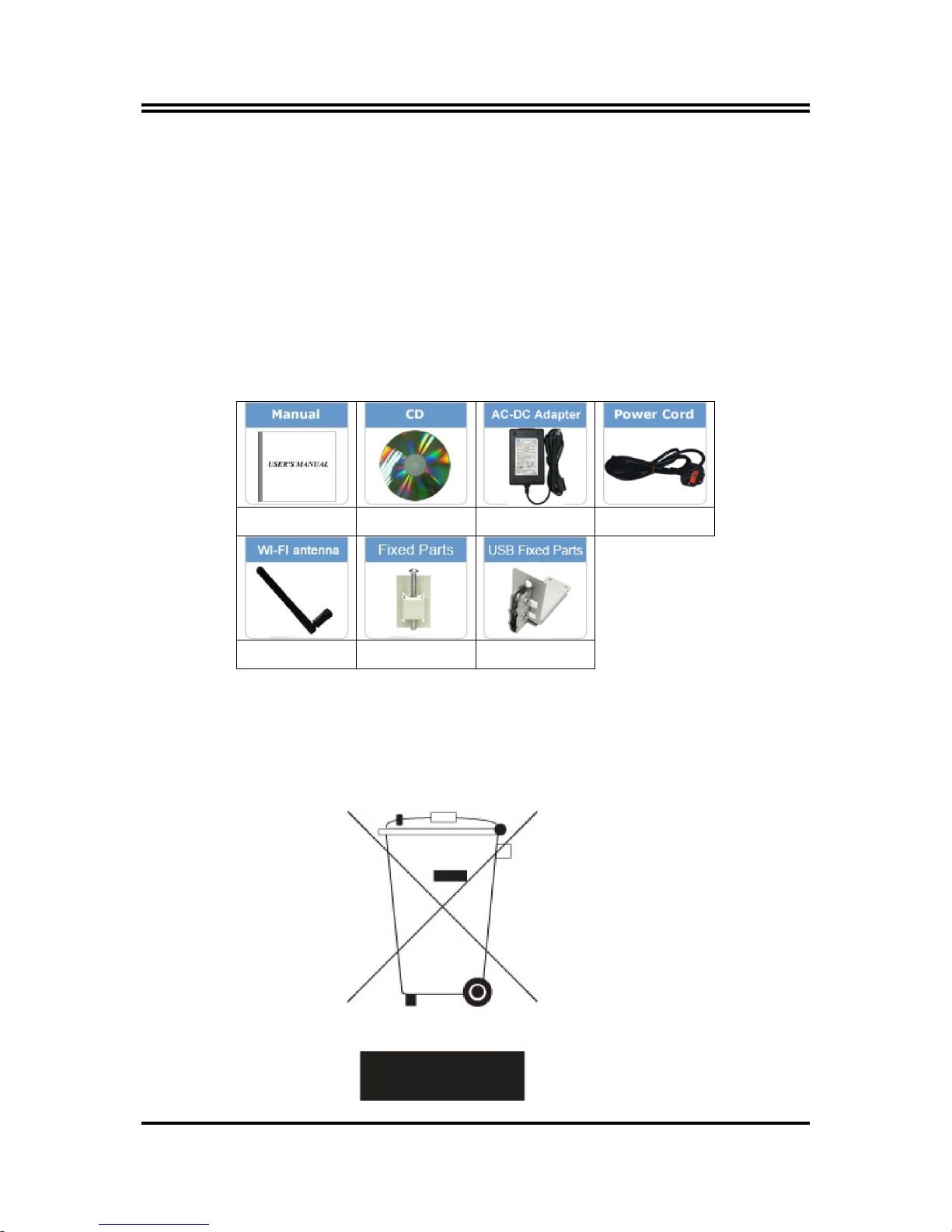
Package Contents
X1 X1 X1 X1
X2 Optional Optional
Environmental Protection Announcement
Do not dispose this electronic device into the trash while discarding. To minimize
pollution and ensure environment protection of mother earth, please recycle.

1
Chapter 1
Introduction
1-1 General Descriptions
Thank you for purchasing the system, a new product developed, designed and
manufactured under leading technical power and consistent dedication to fine
workmanship.
10-points Multi Capacitive Touch
Cable-less,streamlined enclosure for highly efficient heat dissipation enclosed
in robust aluminum casing
Edge-to-edge narrow bezel design and fan-less cooling system
Designed for easy wall mount, panel mount, and VESA mount installation
A true flat, easy-to-clean front surface with edge-to-edge design
USB 3.0 ports support lock device.
IO ports designed for easy connection
IP65-rated front bezel against water and dust
Onboard Intel® Bay Trail series SoC processor, with low power
consumption never denies high performance
Onboard 4GB DDR3L 1333Mhz SO-DIMM
Support 1 * 2.5" SATA HDD Device, 1* Mini PCIe, 1* M.2 connector
Support dual Gigabit LAN
Support 4G SIM card socket
Support 802.11 b/g/n WiFi communication
Support VGA output
Support multiple COM ports
The system has the following features besides other basic functions:
WiFi: the Mini PCI-E onboard socket in the board is integrated a with a WiFi
card(802.11 b/g/n) that can act as a mini wireless modem when external
antennas are connected. Different computers in the house can build wireless
connections through the Mini TOP system and take necessary data from it, thus
reducing the complexity in network establishment.
Giga LAN: The system is integrated with Gigabit LAN network controller with
ACPI management realizing efficient power management for the operating
system.
USB3.0: Experience Fastest data transfers at 5Gb/s with USB3.0 the new latest
connectivity standard. Built connect easily with next-generation components and
peripherals, USB3.0 transfers data 10x faster and backward compatible with
previous USB2.0 components.
CPU Usage: The CPU Usage diagram shows a beautiful data curve that
indicates a pretty low CPU usage percentage for video playback of different
formats. GPU performances are excellent as well.

2
dB Value: The design of the system takes into consideration the needed quiet
operating environment in the living room and the average dB value is below 26
under normal operation to ensure the tranquility when you are absorbed in film
watching.
1-2 Specifications
Main CPU Board
CPU
Intel® Bay Trail series SoC processor
System Memory
Onboard 4GB DDR3L 1333MHz SO-DIMM
BIOS
AMI 64Mb Flash ROM
I/O System
Standard I/O
For HPC101SC-FP1900B Series
1* Power Button
1* Lockable 9~28V DC-in Power Jack
1* VGA
2* RS-232/422/485
2* USB 3.0
2* USB 2.0
2* RJ-45 for Gigabit Ethernet (Intel i211AT)
1* GPIO Port-Male
For HPC156SC-FP1900B & HPC238SC-FP1900B Series
1* Power Button
1* Lockable 9~28V DC-in Power Jack
1* VGA
2* RS-232/422/485 + 2* RS-232
2* USB 3.0
4* USB 2.0
2* RJ-45 for Gigabit Ethernet (Intel i211AT)
1* GPIO Port -Female
3
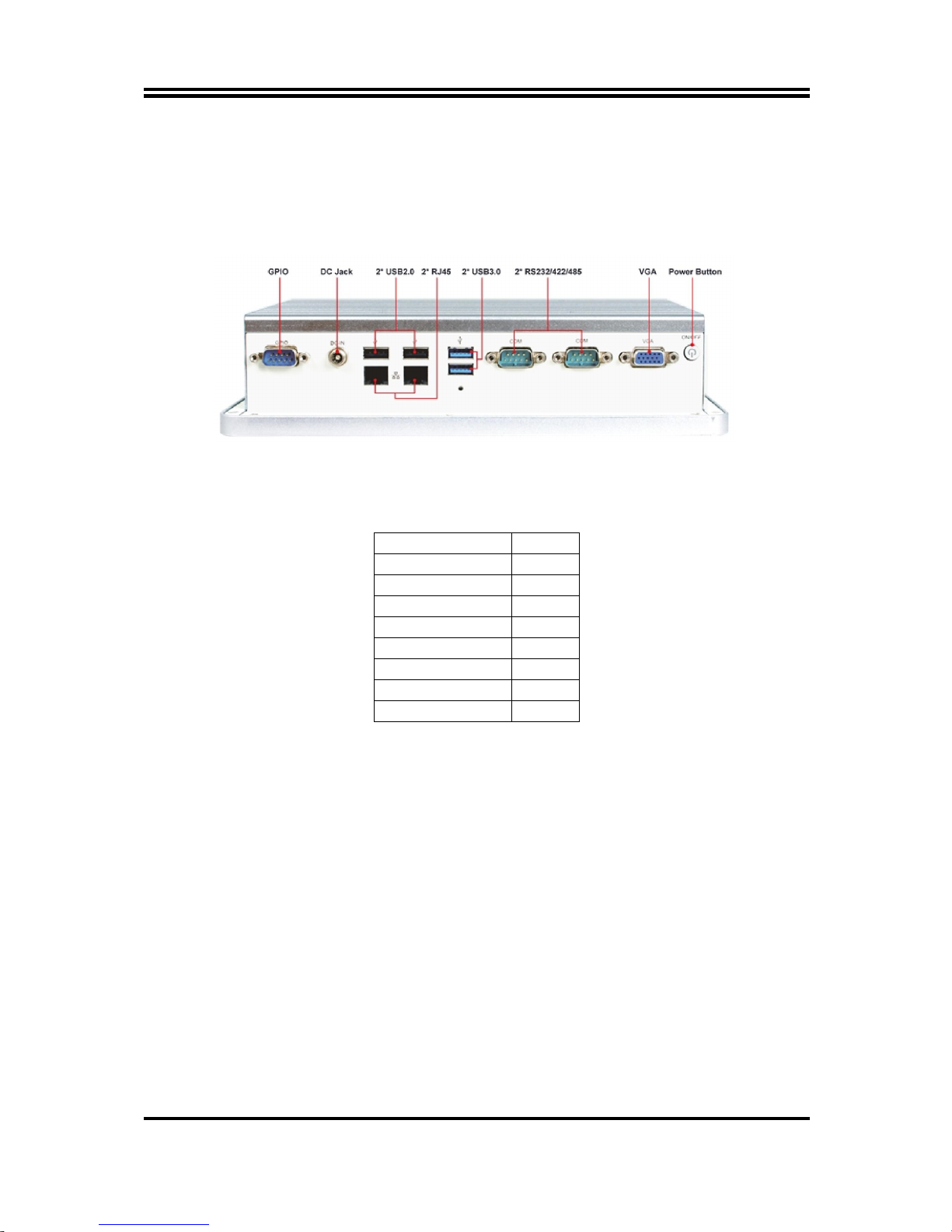
1-3 I/O Outlets
For HPC101SC-FP1900B Series:
Bottom View
Rear IO Q’ty
Power Button 1
DC-in 1
VGA 1
RS232/422/485
2
USB3.0 2
USB2.0 2
RJ-45 2
GPIO-male 1
4
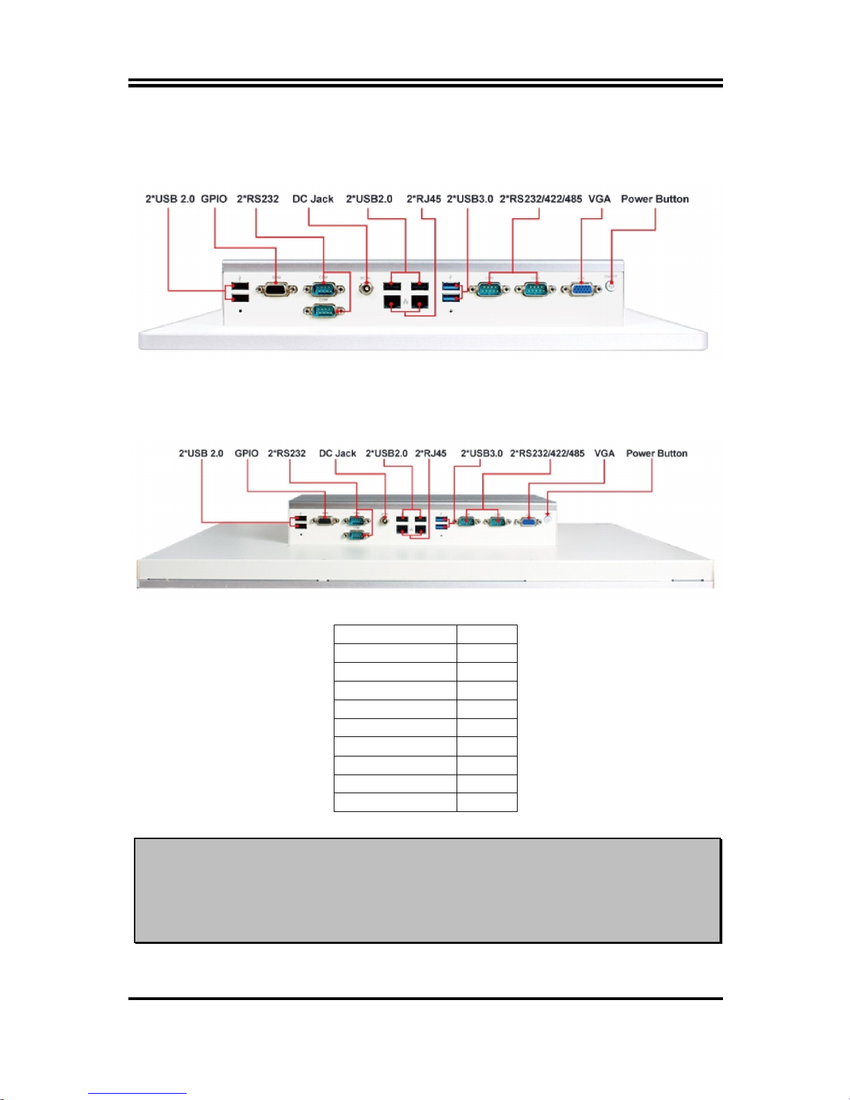
For HPC156SC-FP1900B Series:
Bottom View
For HPC238SC-FP1900B Series:
Bottom View
Rear IO Q’ty
Power Button 1
DC-in 1
VGA 1
RS232/422/485
2
RS232 2
USB3.0 2
USB2.0 4
RJ-45 2
GPIO-female 1
Notice:
1. The diagrams in this manual only serve for illustration, if there is any differences that we
do not cover, please refer to the actual product you purchase.2.Model
HPC156SC-FP1900B& HPC238SC-FP1900B series share the same IO specifications, as
the above diagram shows; 3.The main differences of HPC156SC-FP1900B&
HPC238SC-FP1900B series are mainly in size and panel frame outlook.
5
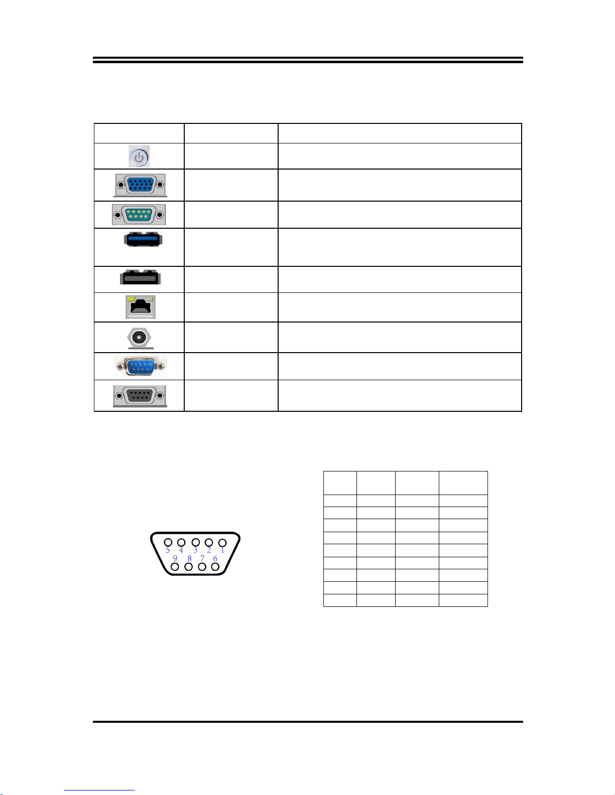
1-4 Connector Pin Definition
(1) Connector Function
Icon Name Function
Power Button
Press to turn on/off the system.
VGA Port
To connect display device that su
pport VGA
specification.
COM Port
Mainly for user to connect external MODEM
or other
devices that supports Serial Communications Interface.
USB 3.0 Port
To
connect USB keyboard, mouse or other devices
compatible with USB specification. USB 3.0 ports
supports up to 5Gbps data transfer rate.
USB 2.0 Port
To
connect USB keyboard, mouse or other devices
compatible with USB specification.
RJ-45 LAN Port
This connector is standard RJ-45 LAN jack
for Network
connection.
DC-in Power Jack
Connector
For user to connect compatible power adapter to provide
power supply for the system.
GPIO
Connector-Male
Male General Purpose Input Output port.
GPIO
Connector-Female
Female General Purpose Input Output port.
(2) I/O Connectors Pin Definition
COM Port Connector
The pin assignment for RS-232/ 422/ 485 is listed as follows:
Pin NO.
RS232 *RS422
(optional)
*RS485
(optional)
1 DCD
TX- DATA-
2 RXD
TX+ DATA+
3 TXD
RX+ NC
4 DTR
RX- NC
5 GND
GND GND
6 DSR
NC NC
7 RTS
NC NC
8 CTS
NC NC
9 RI
NC NC
COM1 & COM2 ports can function as RS232/422/485 port. In normal settings
COM1/COM2 functions as RS232 port. With compatible COM cable they can function
as RS422 or RS 485 port. User also needs to go to BIOS to set ‘Transmission Mode
Select’ for COM1/COM2 (refer to Page 26) at first, before using specialized cable to
connect different pins of this port.
6
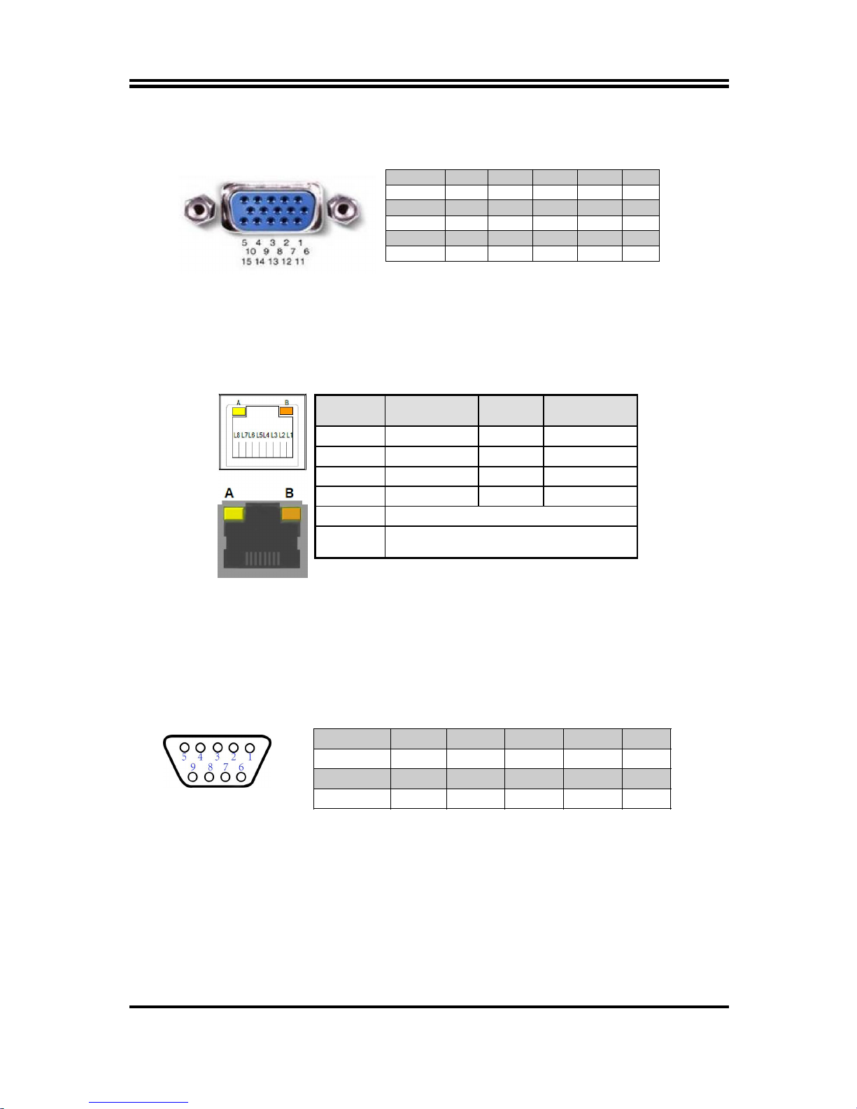
VGA Port Connector
The pin assignment for VGA port is listed as follows:
Pin No. 1 2 3 4 5
Definition
R G B NC GND
Pin No. 6 7 8 9 10
Definition
R-GND G-GND B-GND +5V GND
Pin No. 11 12 13 14 15
Definition NC SDA H-SYN V-SYN SCL
RJ-45 Ethernet Connector
Ethernet connection can be established by plugging one end of the Ethernet cable
into this RJ-45 connector and the other end (phone jack) to a 1000/100/10-Base-T
hub.
The pin assignment for RJ-45 Ethernet LAN connectors are listed as follows:
GPIO (9-pin Block): GPIO Port
GPIO Port Connector
The pin assignment for GPIO connector is listed as follows:
Pin No. 1 2 3 4 5
Definition
GPIO GPIO GPIO GPIO GND
Pin No. 6 7 8 9
Definition GPIO GPIO GPIO GPIO
*Note: GPIO port comes in 2 types: male and female. Please refer to the actual
specification of the product you purchase and choose compatible cable for correct
connection.
Pin Definition Pin Definition
L1 MDI0+ L5 MDI2+
L2 MDI0- L6 MDI2-
L3 MDI1+ L7 MDI3+
L4 MDI1- L8 MDI3-
A
Active LED (Yellow)
B
100 LAN LED (Green) / 1000 LAN LED
(Orange)
7
Chapter 2
Hardware and Installation
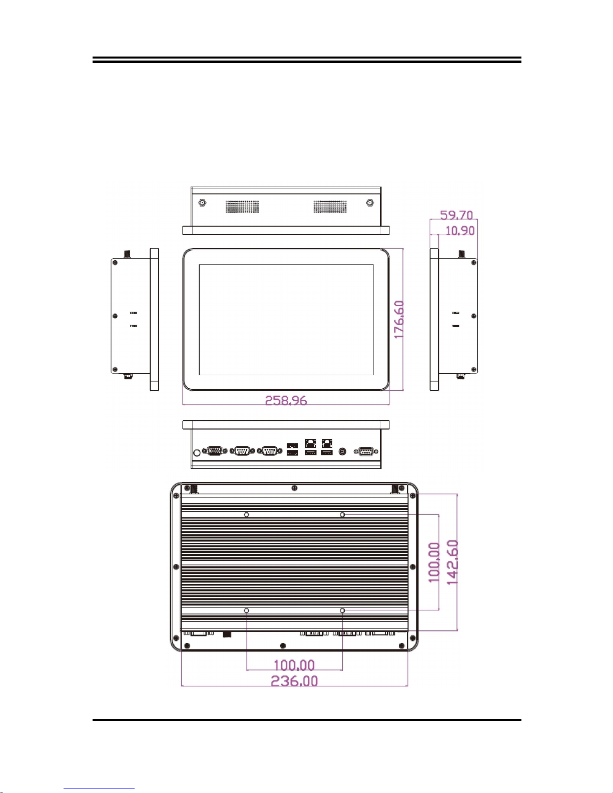
2-1 Dimension and Outlines
Product Dimension for HPC101SC-FP1900B Series:
* Measure Unit: mm.
8
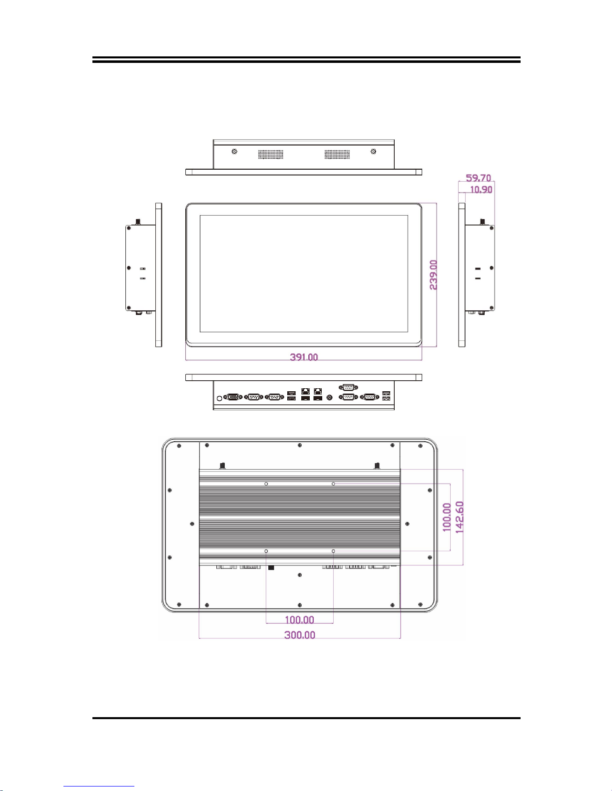
Product Dimension for HPC156SC-FP1900B Series:
* Measure Unit: mm.
9
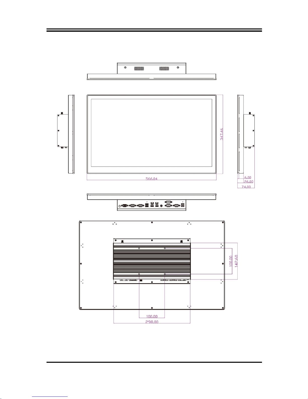
Product Dimension for HPC238SC-FP1900B Series:
* Measure Unit: mm.
10
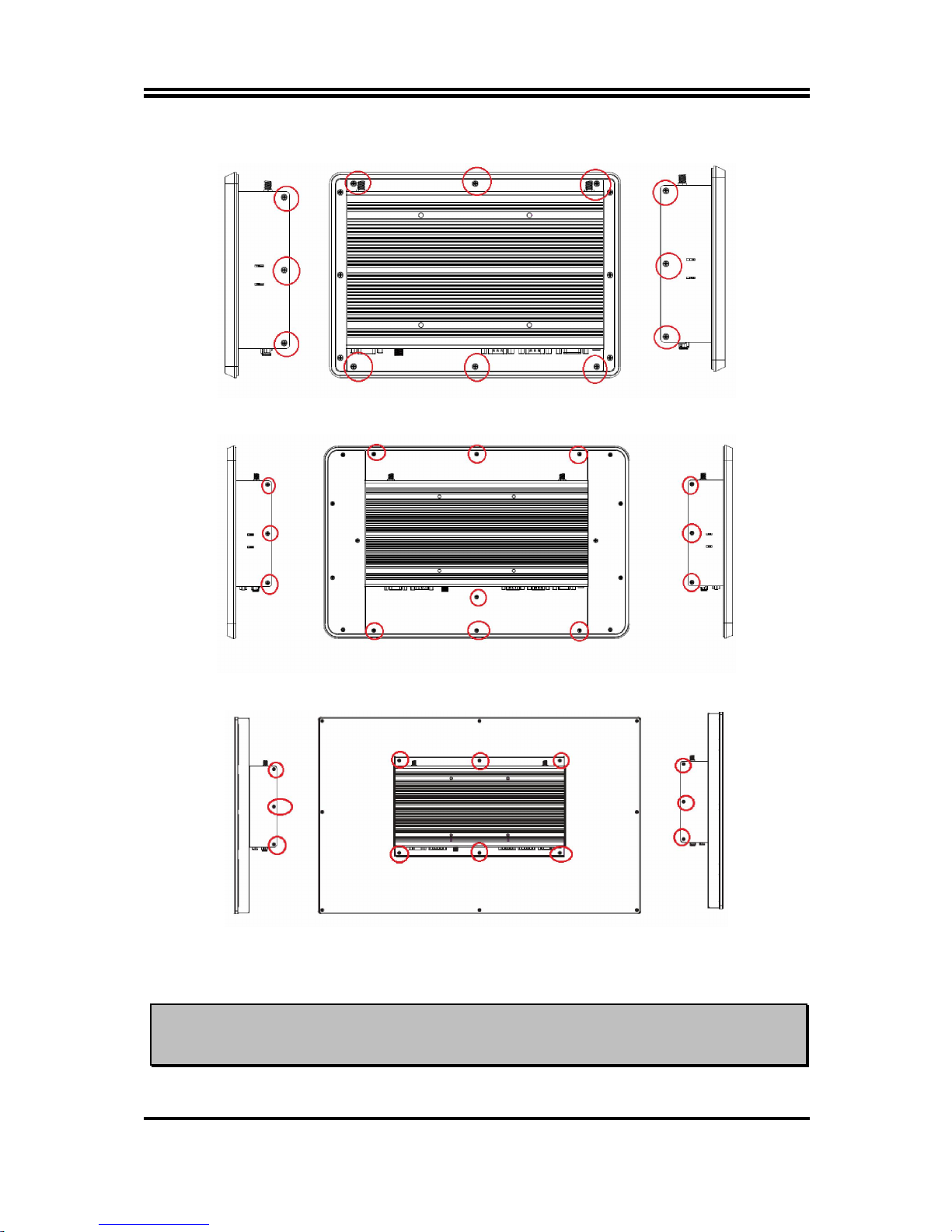
2-2 To Open the Chassis
Use a screwdriver to unscrew the screws marked above that lock the back cover (see red circles).
Remove them to open the chassis.
Notice: When lifting the cover up to open the chassis for further installation, see to it that
the connecting cables are not unplugged. It is very important for the cables connected to
their original places for normal functioning.
HPC101SC-FP1900B
HPC
238SC
-
FP1900B
HPC156SC-FP1900B
 Loading...