

Page 1

Quick Installation Guide
Rev: 1.1
G03-MQ2R2
Page 2

Table of contents
Introduction ................................................................................................1
Features................................................................................................................................1
Advantage ............................................................................................................................1
Remote Control....................................................................................................................2
LCM Display ......................................................................................................................... 4
Setting the LCM Display .....................................................................................................4
System Requirements and Recommendations ................................................................ 5
Preparation for Installation........................................................................6
Package Content .................................................................................................................6
Before You Start ..................................................................................................................6
Hardware Installation .................................................................................6
Installing DIMM Module ......................................................................................................6
Installing CPU ......................................................................................................................7
Installing Hard Disk Drive ................................................................................................... 7
Installing 3.5” Device ..........................................................................................................8
Installing 5.25” Optical Device ...........................................................................................8
Installing Expansion Card ..................................................................................................8
Important Notice.........................................................................................9
i
Page 3

Introduction
Thank you for purchasing MagicTwin series barebone system.
The barebone system is a multi-user ready platform enabling the connection of two users to the
system. With connectivity hardware onboard and the innovative software, the MagicTwin
barebone system allows 2 users to be connected to it and runs up to two (2) stations with
Windows session simultaneously from it. Each of the 2 users feels like having himself his own
Windows-XP computer. Every user needs to have himself his own keyboard, mouse, sound
device, and monitor. The remaining PC hardware will be shared, even the IP. All you need is a
single MiniQ MagicTwin system with a minimum of 1.2 GHz or higher processor, 256MB of RAM
(128MB per workstation/user) and dual VGA port (using a dual port AGP graphic card
purchased separately from your dealer). You can add immediately additional user station to the
single system and turn one PC into two.
The set up is intuitive and easy. In only a few minutes, users can install and start using their new
workstation. No network administrator is needed as everything to network the workstations
together is done automatically with the MagicTwin software. Please refer to the motherboard
manual, MagicTwin XP manual and the electronic PDF manual included in the delivered CD for
detail to configuration this MagicTwin 2-user system.
Features
Onboard Connectivity Hardware for Connecting 2 Sets of Input/Output Devices
MagicTwin Technology for 2 Users to Share One System
Built-in LCM Display for PC Health Information
Wireless Operation by Remote Control on Host (Optional)
Ultra Compact in Small Footprint
Feature-rich for Maximum Flexibility
Aluminum Made for Light Weight and Heat Dissipation
Structured for Better Airflow and Thermal
Designed for Assembly / Upgrade / Service
Value-add for Various Applications
Complete Solution in a Cube
Advantage
Reduced TCO (Total Cost of Ownership)
MagicTwin (technically) runs with only one single Windows-XP Installation and license.
Two users operate simultaneously with single system and share the same processor,
system memory, and so on through MagicTwin.
No network administrator is needed as everything to network the two workstations is done
automatically with the MagicTwin software. You need less software installation, service,
maintenance and administration, which is the most expensive factor in computing.
Time-slicing / Multiplexing Technology for Simplicity and Efficiency
No obvious delay because of the Time-slicing/Multiplexing technology built-in. Each user
gets an exact and extremely short defined moment to access to the PC system, devices,
applications and Windows itself. Resources are only claimed for nanoseconds at a time.
Both users get from W indows and the PC, what they really need when they need it!
Minimal Hardware Requirement with Flexible Expandability
A processor of 1,2GHz and 256MB of system memory are the minimum to start with. You
can upgrade the hardware as time goes and availability comes abundant.
®
series
1
Page 4
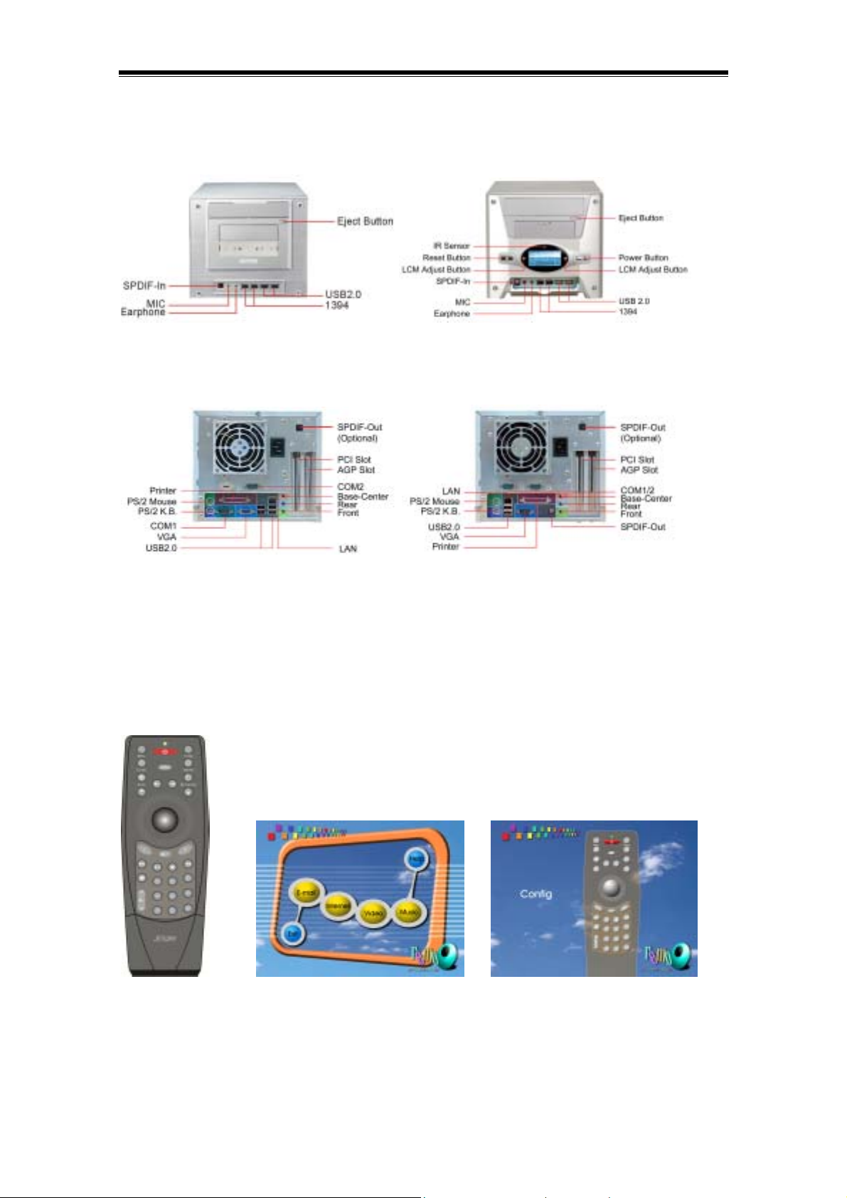
Front Panel
Please refer to the following and select the one that matches the delivered barebone system for
function and feature of various parts.
Back Panel
Please refer to the following and select the one that matches the delivered barebone system for
function and feature of various parts.
Remote Control
The remote control unit is an optional item for the MiniQ barebone system. Only certain models
are equipped with the remote control. Refer to the Check List inclusded in the package for detail.
It comes with a friendly user interface upon powering up the system for direct web browsing,
email accessing, CD playing, and video playing with a touch of the button. Also reserved are 8
programmable keys for user self defined access. It is a 31-key design with track ball built-in.
Note: This remote control can be used only on one station, namely the host PC.
Remote Control remoQ Menu UI remoQ Config UI
The function of all the buttons are detailed as below. The 8 reserved programmable buttons are
marked as C1, C2, C3, C4, C5, C6, C7 and C8. You can used the Config UI to configure those
buttons as what you need.
2
Page 5

Power
This key will let you boot up the system from stand-by mode and lead you through to
Windows, and close the Windows. (Please enable “keyboard power on password as P”
Menu
This key lets you go to the main menu screen. Move the cursor to the desired
selection to activate the function.
Config
This key let you to configure reserved C1 to C9 keys as personalized Internet web
pages, such as shopping, news, radio, stock, and so on. Pressing the key will activate the
Config screen. Just move the cursor to the reserved C1 to C9 to set the web pages.
E-Mail
This key will launch the default mail application installed on your system. If there is
no response after you press this key, check the default mail application by selecting the
Internet option applet from the control panel.
Internet
This key will launch the default Internet Browser.
The browser will go to the home page set for the browser.
Zoom
This key will let you zoom in and out the cursor vicinity screen or activate the application
built-in scale feature. It is arranged in rotating order of zoom in and zoom out.
My Favorite
Open My Favorite after entering Internet browser application.
Scroll Up
This key will let you scroll up the screen.
Scroll Down
This key will let you scroll down the screen.
Next Page
This key will bring you to the next Internet pages accessed before.
Previous Page
This key will bring you back to the previous pages accessed before.
Track Ball
This track ball built-in let you move the cursor around just by rolling the ball. You
can drag the cursor or selected area by pressing and holding the track ball down in
position. It works as Mouse.
L
This key works as left button on mouse.
R
This key works as right button on mouse.
Enter
This is Enter key.
Media
Select CD, VCD or DVD and multimedia driver.
Play / Pause
Start to play CD title, continue playing the tile, or pause the current play status.
3
Page 6

Stop
Stop playing and return to the beginning position of the track.
Next track
Skip the current track and go to the beginning position of the next track. If the current track
is the last track, this button will lead you to the first track.
Previous track
Skip the current track and go to the beginning position of the previous track. If the
current track the is first track, this button will lead you to the last track.
Mute
Toggle the sound mute or not mute.
Volume up
Increase the main volume of the sound.
Volume down
Decrease the main volume of the sound.
LCM Display
There are two type of front panels. Certain models come equipped with LCM display on the
front bezel. Please check specifications. The LCM screen provides you with the system health
information (CPU temperature, system temperature, and CPU fan speed), time, power indication,
HDD activity, LAN activity, and optical device activity in graphic. The temperature (℃) and fan
speed (rpm) displayed are real-time fetched from the system through I²C bus. The information is
intended to provide you with the up-to-date system health for your easy monitoring of system
status.
Setting the LCM Display
Right LCM Adjust Button Left LCM Adjust Button
Upon power-on the system LCM display will come up with a welcome message “Hello!” for three
seconds.
4
Page 7

The display will then resume to Always-on display mode. Under this mode you will see power
indication, HDD activity, LAN activity, optical device activity, and time on screen.
The LAN activity icon will blink when the network is accessed, The DISC activity icon will blink
when the optical device is accessed. The HDD activity icon will blink when the hard disk is
accessed.
LAN Activity Display Optical Device Activity Display HDD Activity Display
Right Button - select display mode clockwise, CPU TEMP SYS TEMP FAN rpm TIME
Left Button - select display mode counter-clockwise, FAN rpm SYS TEMP CPU TEMP
TIME
CPU TEMP Mode SYS TEMP Mode
CPU FAN rpm Mode
The LCM display will resume to the always-on display after 1 minute of display of CPU
temperature, SYS temperature and CPU FAN rpm mode.
Clock Adjustment – press both left and right button simultaneously to enter into clock adjustment
mode when in TIME mode. The time displayed is in 24-hour system as in “hh:mm” format. You
will see “hh” blinking when entering the clock adjusting mode. Press the right button to adjust the
“hh” hour time upward. Press the left button to confirm the hour time adjustment. You will be
switched to the “mm” minute time adjustment mode in the same time. Adjust and confirm the 1
digit and the 2
nd
digit in turn the same way as above. When it is completed the screen will
st
resume to always-on display mode.
System Requirements and Recommendations
We strongly urge that the following system requirements are met. Every MagicTwin system
needs two VGA-ports. You can purchase the dual head AGP VGA card separately from your
dealer.
5
Page 8

User Type Standard User Power User Multimedia User
Application Office, Internet, Email Database, DTP- and Sound, Movies/MPEGs
SOHO Application Graphic –Applications Graphic Applications
max. 3 simultaneous 10 applications
Processor >= 1.2 GHz >= 1.2 GHz >=1.2 GHz
RAM min. 256MB min. 384MB min. 512MB
VGA Port NVIDIA Dual Head AGP VGA Card ( Purchased Separately)*
OS Windows XP Home or Professional Edition with Service Pack 1
* You do not need to purchase separately a dual head VGA card if your system is equipped with
motherboard of NVIDIA nForce2 integrated graphic chipset. Please refer to MagicTwin
Hardware Installation section of MagicTwin XP manual for detail.
Preparation for Installation
The Quick Installation Guide is intended to provide you with the basic information regarding the
barebone system and help you complete the installation successfully. Upon receiving the system,
please first check the package and the content.
Package Content
Bare-bone System Unit
Accessory Box
Power Cord
Driver CD
Manual
Screw Set and Cable Set
Cable Set
CPU Cooler Set (inside of case)
Remote Control (Optional)
Before You Start
The voltage of PSU (power supply unit) is either 220V or 110V, without switch. Make sure the
power supply voltage is matching your AC power input before plugging the power cord.
Hardware Installation
First, loosen the three thumbscrews from the rear of the system unit to remove the top cover.
Hold both sides of the top cover, push the back panel, and lift upward to open the case. Please
follow the installation procedure and sequence described in this guide for smooth assembly.
Installing DIMM Module
To install the memory module, first open the two locking levers on the DIMM socket. Align the
DIMM to the socket and push vertically down firmly from the top edge of the DIMM. Click back
the locking levers toward the DIMM. The DIMM module can only fit in one direction according to
the keyed notch.
6
Page 9

Installing CPU
Push the CPU socket lever sideway out and lift up to 90° angle.
Locate Pin 1 on the socket and align cut edge of the CPU to it. Insert the CPU onto the socket,
press the CPU from top evenly by hand, and pull back the CPU socket lever to lock the CPU in
position. Apply thermal tape (recommended) or thermal paste to provide better heat conduction
between CPU and heatsink. Make sure the heatsink is in good contact with CPU to avoid overheat or damage. Please use an Intel or AMD approved CPU cooling system. Connect the CPU
fan power cable to fan connector on motherboard. Plug the cooling system (heatsink and cooling
fan) to the CPU retention module in correct direction. Follow the instructions and precautions
from CPU, heatsink and cooling fan to complete the installation.
P4 Socket 478
Socket A
Installing Hard Disk Drive
Loosen screw and pull out the HDD bracket from its rail. Place HDD onto the correct position on
the bracket and screw to fix the HDD. Slide back the bracket with HDD on to its rail and tighten
the screw. Connect HDD cable from IDE1 connector on motherboard to HDD. The HDD cable
comes with three connectors. Always use the first two connectors for the first HDD connection.
Make sure the red stripe of the cable is aligned to the pin 1 of connector. Insert firmly to insure
the contact. (If Serial ATA is supported on the motherboard, just connect the Serial ATA cable
come packaged with the accessory box to HDD and motherboard). Connect power cable to
power connector on HDD.
7
Page 10

Installing 3.5” Device
Hold the 3.5” device from the back and place it down from the top of the case to fit in the position
with device bezel down for smooth operation. Lower the tail part that you are holding to level and
push forward to align the mounting holes on 3.5” device with the case mounting holes. Screw to
fix it in place. Connect FDD cable from FDD1 connector on motherboard to FDD. Make sure the
red stripe of the cable is aligned to pin 1 of connector. Insert firmly to insure the contact.
Connect the small 4-pin power connector to the FDD. (Refer to the instruction of the respective
device If other 3.5” device is installed).
Installing 5.25” IDE Optical Device
Hold the optical device from the back and place it down from the top of the case with device
bezel tilting down to contact the 5.25” cavity. Lower the tail part that you are holding to level and
push forward to align the mounting holes of optical device with case mounting holes. Tighten the
screw to fix the device in place. You might need to adjust forward or backward to locate the
appropriate horizontal position of the optical device. (Please refer to Important Notice section).
Connect IDE cable from IDE2 connector on motherboard to optical device. Make sure the red
stripe of the cable is aligned to Pin 1 of connector. Insert firmly to insure the contact. Locate the
cable clip on the outside on HDD bracket and clip the IDE cable onto it. Connect power cable to
the device.
Installing Expansion Card
Remove the expansion card bracket on the back of the case by unscrewing the bracket holding
plate on top of it. Plug in the expansion card vertically down firmly to its end position. Screw the
bracket holding plate back to firmly to fix the expansion card bracket in position.
Completing Installation
Put back the top cover gently and tighten the thumbscrews to complete the installation. You are
now ready to explore the feature-rich system.
8
Page 11

Important Notice
Please read this before you start to install optical device.
To avoid possible damage to the 5.25” device revolving door cover of the MiniQ system case, it
is highly recommended that you remove the bezel/facial plate on the tray of optical device before
installation. Please refer to the following picture for detail.
1. push out the tray 2. remove facial plate on tray 3. complete
Optical devices and mechanical parts have their dimension tolerance. They might differ in size.
To make sure the optical device has fine contact with the EJECT button in the back of front
bezel of MiniQ system, the 5.25” device bay bracket has two kinds of screw hole for micro
adjustment of device fixing position:
1) Upper row of three screw holes are suitable for most of the market available CD-ROM / DVDROM / DVD-RW (See picture 1). The third screw hole from front bezel is for micro adjustment of
position, if necessary
2) If position of these three screw holes cannot match your CD-ROM / DVD-ROM / DVD-RW
(such as SONY DVD-ROM Model: EDU-1621), you can opt to use the long oval hole beneath
the three screw holes for fine contact. (See picture 2)
Picture 1 Picture 2
9
 Loading...