

Page 1

994AN/994AN-L
994AS/994AS-L
USER'S MANUAL
PCI/ AGP Mainboard
For Pentium II/ III or Socket 370
The author assumes no responsibility for any errors or omissions which
Trademark:
* Pentium is registered trademark and MMX is a t r ademark of Intel corporatio n ,
the other names and brands are the property of their respective owners.
* Specifications and Information contained in this documentation are furnished for information use only, and are subj ect to
change at any time without notice, and should not be construed as a commitment by man ufacturer.
ma y a ppear i n t his d ocu men t no r does i t make a commitment to update
the information contai n ed herein.
Release date: NOV 2000
NO. G03-994ANR4A
** Year 2000 compliant **
Page 2

Chapter 1
1-1 Preface.............................................................................................................1
1-2 Feature of motherboard.................................................................................... 1
1-2-1 Overview............................................................ .................................. 1
1-2-2 Key Feature........ .................................................................................2
TABLE OF CONTENT
Chapter 2
Hardware Installation
2-1 Unpacking........................................................................................................3
2-2 Mainboard Diagram..........................................................................................4
2-3 Quick Reference for Jumpers, Connectors & Expansion Socket.......................5
2-4 Installation Steps.............................................................................................. 6
2-5 Jumper Settings ............................................................................................... 6
2-6 System Memory (DRAM)..................................................................................7
2-7 Central Processing Unit (CPU)......................................................... ................ 7
2-8 Expansion Cards..............................................................................................10
2-9 External Connectors.........................................................................................11
.................................................................................. 3
Chapter 3
AWARD BIOS SETUP
3-1 STANDARD CMOS FEATURES......................................................................18
3-2 ADVANCED BIOS FEATURES........................................................................19
3-3 ADVANCED CHIPSET FEATURES .................................................................21
3-4 INTEGRATED PERIPHERALS.........................................................................22
3-5 POWER MANAGEMENT SETUP .................................. .................................. 23
3-6 PnP/PCI CONFIGURATIONS..........................................................................24
3-7 PC HEALTH STATUS......................................................................................25
3-8 FREQUENCY/VOLTAGE CONTROL............................................... ................ 26
3-9 LOAD OPTIMAL DEFAULTS............................................................................ 26
3-10 LOAD STANDARD DEFAULTS........................................................................27
3-11 SET SUPERVISOR/USER PASSWORD ...................................................... ... 27
3-12 SAVE & EXIT SETUP/EXIT WITHOUT SAVING..............................................27
.................................................................................. 17
Chapter 4
Software Installation............................................................................................28
4-1 Mainboard Driver Install in Wi n9X,WinNT.........................................................28
4-2 PC HEALTH MONITOR-III................................................................................ 29
4-3 SOUND Driver (Option for motherboard that embedded Audio chip)................31
APPENDIX-A Magic Install........................................................................46
i
Page 3

Chapter 1
1-1 Preface
Thank you for purchasing this multifunction motherboard. It has the mos t flexibility you can find
in today’s computer market. The mainboard integrates both Intel Pentium®II / Pentium®III &
Celeron™(Slot 1) / Coppermine processor and Celeron™ (Socket 370) PPGA / FCPGA
processor interface into a compact PC/ATX compatible system along with next generation of 4X
AGP specification, 133MHz FSB, Ultra DMA66, and optional 3D Stereo Sound System audio
chip. Moreover, this mainboard allows you conditionally approach 140MHz* of Front Side Bus
Frequency to accelerate your CPU speed.
1-2 Feature of motherboard
This motherboard is design for the PC user who wants highest possible quality and value in a
small package. It includes following main features:
1-2-1 Overview
• Support both Slot 1 & Socket 370 CPU interface (You can only use one CPU interface
at a time).
• Support Ultra DMA 66 for newer hard disk interface.
• Support Jump-less solution for s etting Front Side Bus Frequency (CPU Host Clock)
and CPU ratio u nder CPU Host/PCI clock of CHIPSET FEATURES SETUP.
• Support CPU Host Clock and DRAM Clock Asynchronous/Synchronous mode, please
refer page 25 “ DRAM Clock”.
• Conditionally support 66MHz~140MHz* of Front Side Bus Frequency. This function
allow user select CPU Bus Frequency by the BIOS to approach Over-Clock possibility.
• Provide PC Health Monitoring to track CPU temperature, system temperature, system
voltage, and fan speed. When CPU current temperature is over CPU warning
temperature, system will slow down automatically in order to reduce the CPU’s
temperature. (Option for motherboard that embedded PC Health chip)
• Logo-DIY: Provide CBROM utility for user to create their own loge in the BIOS.
• Built in high quality PCI-Based HRTF 3D Extension Positional Audio Chip (Option for
motherboard that embedded Audio chip)
- Supports rear side speakers, C3DX positional audio in 4 channels speaker mode.
- Professional digital audio interface to support 24-bit SPDIF IN and OUT (44.1K and 48K
format).
- HRTF-base 3D positional audio, supporting DirectSound™ 3D and Aural A3D™ interface.
- Digital functions that capable to provide hi-fi stereo, Dolby, 3D surround effects, and
playing MP3 music.
• You can add our Optical kit (Option for motherboard that embedded Audio chip) to
connect any optical Input/Output device for super high quality sound transaction,
such as playing & recording MD(Mini Disk)/CD; CD-ROM directly recording to MD;
combine with DVD player to create a home theater system (This upgrade kit includes
Optical Module, Optical Cable, and Software DVD Driver).
1-2-2 Key Feature
1
Page 4

• Multi-Speed Support:Provide 66/75*/83*/95*/100/112*/117*/124*/133*/140*MHz Front
Side Bus Frequency to support Intel Pentium®II / Pentium®III / Coppermine / Celeron
processor for Slot1 interface or Intel Celeron PPGA / FCPGA on a ZIP Socket 370 interface.
• Chipset: VIA 82C694X Apollo Pro-133A Chipset.
• DRAM Memory Support:Support 3 x 168-pin DIMM sockets (3.3V) for memory from 8M
Byte to 1.5GB Byte in either EDO (66MHz only) or SDRAM (66MHz/100MHz/133 MHz) type
module with ECC or parity check.
• AGP, ISA, and PCI expansion Slots:Provide a 4X AGP slot, one 16-bit ISA slot, and four
32-bit PCI master slots.
• Super Multi-I/O: Provides two high-Speed UART compatible serial ports and one parallel
port with EPP and ECP capabilities. Two floppy drives of either 5.25” or 3.5” (1.44MB or
2.88MB) are also supported without an external card.
• PCI Bus Master IDE Controller and ULTRA DMA 33/66 : On-board PCI Bus Master IDE
controller with two connectors that supports four IDE devices in two channels, provides
faster data transfer rates, and sup ports Enhanced IDE devices such as Tape Back up, CDROM, ZIP, LS-120 Drives. This controller also supports PIO Modes and Bus Master IDE
Ultra DMA 33/66Mbyte/Second.
• ACPI supporting for OS Directed Power Management.
Ring-In Wake up: When Ring-In the system can wake up from SMI Mode.
Ring-In Power On: When Ring-In the system can power on automatic by this function.
RTC Power On: Enabled RTC Power On function, you can set RTC alarm to power on the
system at the time leng th th at co rre spond to your setting.
Power Button: Press the button will place the system power on/off.
Wake on LAN : The system can power on by server in Network.
Support Softwa re Power Off function.
• Power Support: Efficient PWM switching power instead of traditional Linear Voltage
Regulator to prevent power component from being burned-out.
• PC 99 ready
• PS/2 Mouse: This mainboard support PS/2 mouse set.
• USB Port Connec tor: This mainboard supports two USB port connectors for USB devices.
• Optional IrDA: This mainboard supports an optional infrared port module for wireless
interface, with independent 3rd UART (32-byte FIFO).
• 4X AGP: Accelerated Graphics Port to support up to 1GB/sec data transfer rate and
266MHz 4X mode for AD and SBA signaling.
• ATX Form Factor: Dimensions 30.5cm x 19cm.
* Your memory module(s) mus t be PC133 complia nt SDRAM chips and speci fied to run
on 133MHz or 140MHz.
* When you are running at 140MHz, make sure all of your PCI devices have enough
tolerance to run on 37.5MHz . Otherwise, it may cause your system become very
unstable.
Chapter 2
2
Page 5

Hardware Installation
2-1 Unpacking
This mainboard package should contain the following:
• The mainboard
• USER’S MANUAL for mainboard
• Cable set for Ultra DMA 66 IDE x1, Floppy x1
• CD for Drivers PACK
The mainboard contains sensitive electronic components that can be easily damaged by
electron-static, so the mainboard should be left in its original packing until it is installed.
Unpacking and installation should be done on a grounded anti-static mat.
The operator should be wearing an anti static wristband, grounded at the same point as the anti-
static mat.
Inspect the mainboard carton for obvious damage. Shipping and handling may cause damage to
you r bo a r d . B e s u r e there are no sh i p p i n g a nd handling damages on the board before proceeding.
After opening the mainboard carton, extract the system board and place it only on a grounded
anti-static surface component side up. Again inspect the board for damage.
Press down on the entire socket IC’s to make sure that they are properly inserted. Do this only
on with the board placed on a firm flat surface.
Warning: Do not apply power to the board if it has been damaged.
You are now ready to install your mainboard. The mounting hole pattern on the mainboard
matches the ATX system board.
It is assumed that the chassis is designed for a standard ATX main board mounting. Place the
chassis on the anti-static mat and remove the cover.
Take the plastic clips, Nylon stand-off and screws for mounting the system board, and keep
them separate.
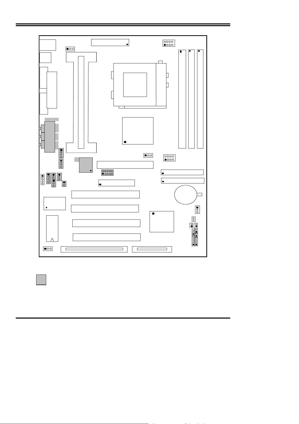
2-2 Mainboard Diagram
3
Page 6
T
J5
US
N
U
AGP1JP2JP3
D
J
J3
MINI-
B
J1
CPUFAN
DIN
J4
ATX POWER CONN.
U10
U20
DIMM1
J2
IR1
POR
COM2
COM2 COM1
GAME1
AGC
SPKIN 1
JP1
P4
U3
ALI M5135
BIOS
U4
LINE-OUT
LINE-I
MIC
SPD IF IN 1
SPDIFOUT
SL1
CP
SLO T-1
ZI F SOCKET 370
U12
VIA82C694X
U7
U8
C MI8738
FDD
PCI1
U19
IDE2
IDE1
PCI 1
PCI2
U17
PCI3
PCI4
VIA82C596B
PCI 4
DIMM1
IDE2
BATT.
SMI
PS-ON
TBSW
DIMM2
KEYLOCK
DIMM3
BT1
+
JP16
HDLED
RST TBLE
SPEAK ER
JP15
Figure 2-2
Option for motherb oard that embedded with Audio Chip
2-3 Quick Reference for Jumpers, Connectors & Expans ion Socket
Jumpers
4
Page 7
Jumper Name Description Page
U19 CPU Bus Frequency Selection Refer to page 6 p. 6
U20 CPU Ratio Selector Refer to page 6 p. 6
JP16 CMOS RAM Clear 1-2 Normal ,2-3 Clear CMOS p. 7
Connectors
Connector Name Description Page
PL1 ATX Power Connector 20-Pin Block p.9
MINI-DIN PS/2 Keyboard/PS/2 Mouse 6-Pin Female p.9
USB USB Port Connector 5-Pin Connector p.9
PRINT Parallel Port Connector 26-Pin Female p.9
COM1, COM2 Serial Port COMA , COMB 9-Pin Connector p.10
FDD Floppy Driver Connector 34-Pin Block p.10
IDE1 Primary IDE Connector 40-Pin Block p.10
IDE2 Secondary IDE Connector 40-Pin Block p.10
HDLED IDE activity LED 2-Pin Connector p.11
SMI SMI Suspend Switch 2-Pin Connector p.11
JP15 Front Panel Connector 16-Pin Block
IR1 Infrared Module Connector 10-Pin Block p.12
CPUFAN, SYSFAN FAN Connector Extra fanning system connectors p.12
PS-ON ATX power button/soft power button 2-Pin Connector p.12
WOL Wake On LAN 3-pin Block P.12
p.11
Jumpers & Connectors (Option for motherboard that embedded Audio chip)
Item number Name Description Page
JP4 On-Board Sound Enable/Disable 1-2 : Disabled , 2-3 : Enabled p.13
JP1 AUX IN 4-pin Block p.13
JP2 CD-Audio 4-pin Block p.13
JP3 CD-Audio 4-pin Block p.13
AGC Line IN/Line Out/MIC /Game Connector 15-pin Connector + 3 phone jack p.13
SPKIN 1 PC Speaker In 2-pin Block p.14
SPDIFIN 1 SPDIF (Sony/Philips Digital Interface) IN 3-pin Block p.14
SPDIFOUT SPDIF (Sony/Philips Digital Interface) OUT 2-pin Block p.14
JP9 For Optional Optical Kit Connector 10-pin Connector p.14
Expansion Sockets
Socket/Slot Name Description
DIMM1,DIMM2, DIMM3 DIMM Module Socket 168-Pins DIMM SDRAM Module Expansion Socket
Slot1 CPU Slot Pentium II/III / Coppermine CPU Slot
Zip Socket370 CPU Socket Celeron PPGA / FCPGA CPU Socket
AGP SLOT 4X AGP SLOT AGP Expansion Slot
PCI1, PCI2,PCI3 ,PCI4 PCI Slot 32-bit PCI Local Bus Expansion slots
SL1 ISA Slot 16-bit ISA Bus Expansion slot
2-4 Installation Steps
Before using your computer, you must follow the steps as follows:
1. Set Jumpers on the Mainboard
5
Page 8
y
2. Install the CPU
3. Install DRAM Modules
4. Install Expansion card
5.
Connect Cables, Wires, and Power Supply
2-5 Jumper Settings
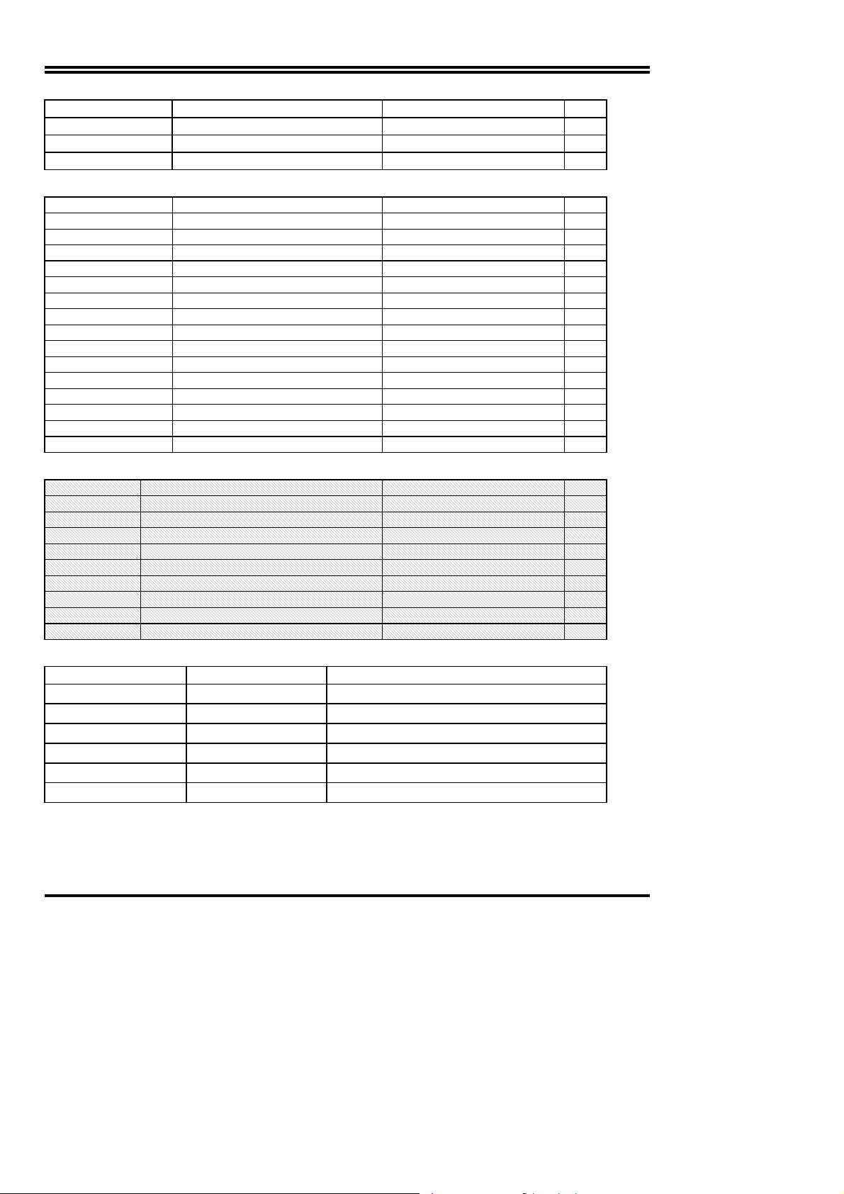
1. CPU Bus Frequency Selection :
U20
5678
1234
5678
1234
•
Users also can setting the CPU Bus frequency in the “CPU Host/PCI clock” in
CHIPSET FEATURES SETUP.(Please refer to page 25)
2. CPU Ratio Selector:U20
Ratio 1-5 2-6 3-7 4-8 Ratio 1-5 2-6 3-3 4-8
3.0x ON OFF ON ON 5.5x OFF OFF OFF ON
3.5x OFF OFF ON ON 6.0x ON ON ON OFF
4.0x ON ON OFF ON 6.5x OFF ON ON OFF
4.5x OFF ON OFF ON 7.0x ON OFF ON OFF
5.0x ON OFF OFF ON 7.5x OFF OFF ON OFF
8.0x ON ON OFF OFF
CPU External Frequenc
*Your Memory must meet the requirement to run on 133MHz or 140MHz
condition. In order to run 140MHz, Please set jumper at 133MHz condition and
then change the setting to140MHz from the BIOS.
Table for the Pentium III and Celeron Socket 370 CPU
Celeron Pentium III Pentium III
Speed Bus Ratio Speed Bus Ratio Speed Bus Ratio
300/66 66MHz 4.5x 500E/100 100MHz 5.0x 733/133 133MHz 5.5x
333/66 66MHz 5.0x 533EB/133 133MHz 4.0x 750/100 100MHz 7.5x
366/66 66MHz 5.5x 550E/100 100MHz 5.5x 800/100 100MHz 8.0x
400/66 66MHz 6.0x 600E/100 100MHz 6.0x 800EB/133 133MHz 6.0x
466/66 66MHz 7.0x 600EB/133 133MHz 4.5x 850/100 100MHz 8.5x
500/66 66MHz 7.5x 650/100 100MHz 6.5x 866/133 133MHz 6.5x
533/66 66MHz 8.0x 667/133 133MHz 5.0x 933/133 133MHz 7.0x
533A/66 66MHz 8.0x 700/100 100MHz 7.0x 1.0GHz/133 133MHz 7.5x
566/66 66MHz 8.5x
600/66 66MHz 9.0x
633/66 66MHz 9.5x
667/66 66MHz 10.0x
700/66 66MHz 10.5x
733/66 66MHz 11.0x
766/66 66MHz 11.5x
∗ Because the Ratio are fixed by CPU Manufacture, users don’t need
U19
:U19
CPU 1-5 2-6 3-7 4-8
66.8 OFF OFF ON ON
75 OFF ON ON ON
83 ON OFF ON ON
100 OFF OFF OFF ON
124 ON OFF OFF OFF
133 OFF OFF OFF OFF
to setting ratio any more, this table just for reference use.
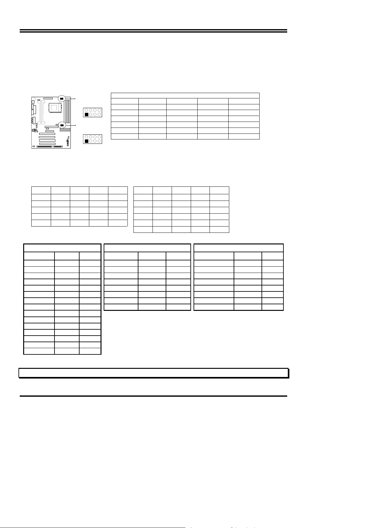
2. CMOS RAM Clear: JP16 (Yellow color selector)
WARNING: Make sure your computer is POWER OFF when you CLEAR CMOS.
6
Page 9
)
Connect a jumper Cap over this jumper for a few seconds, will clears information stored in the
CMOS RAM Chip that input by user, such as hard disk information and passwords. After
CLEAR CMOS, you must enter the BIOS setup (by holding down <DEL> during power-up) to reenter BIOS information (see BIOS SETUP).
Selections JP16
Normal 1-2 (Default)
Clear CMOS 2-3 (momentarily)
JP16
1
2
3
Clear CMOS
JP16
1
2
3
Normal
CMOS RAM (Normal / Clear CMOS Data
2-6 System Memory (DRAM)
This mainboard supports three 168-pins DIMM modules, the Max Memory Size is 1.5GByte.
DIMM 1
168-pin DIMM
168-pin DIMM 168-pin DIMM
168-pin DIMM
DIMM 2 DIMM 3 System can be Accept or Not
x x Accept
168-pin DIMM 168-pin DIMM
x Accept
Accept
2-7 Central Processing Unit (CPU)
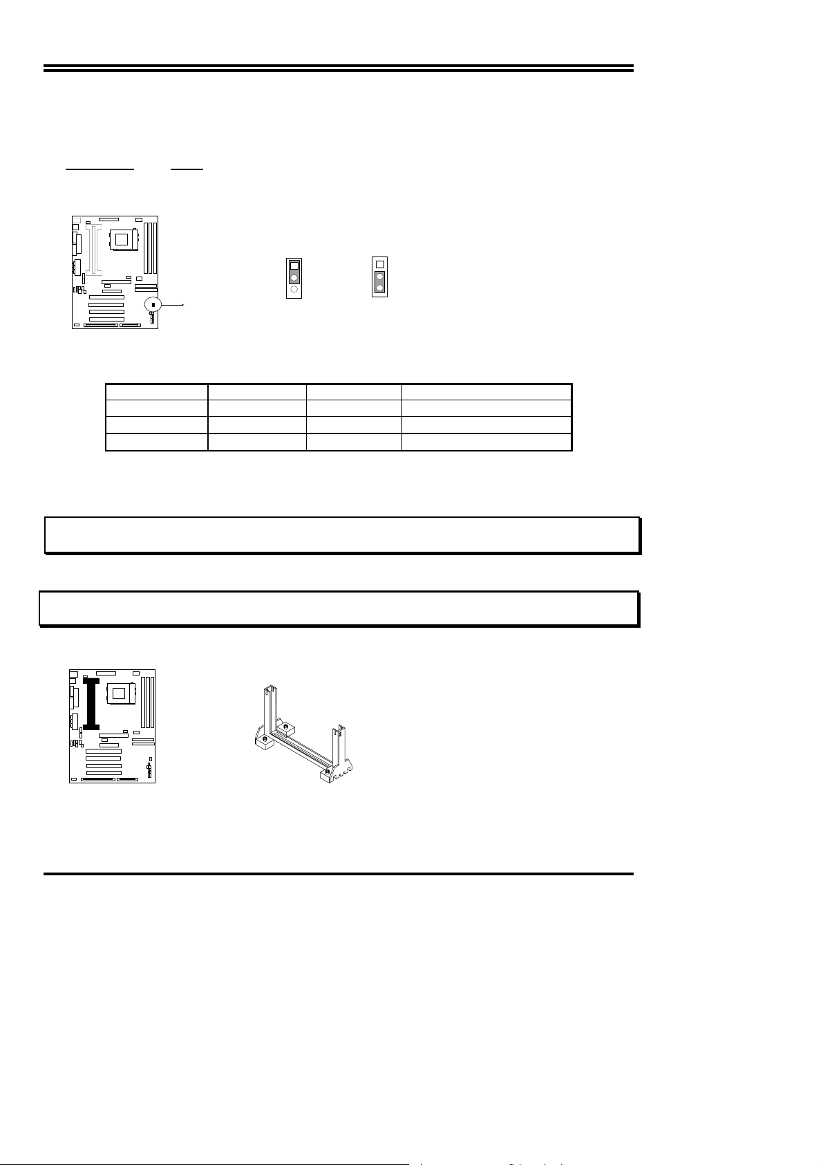
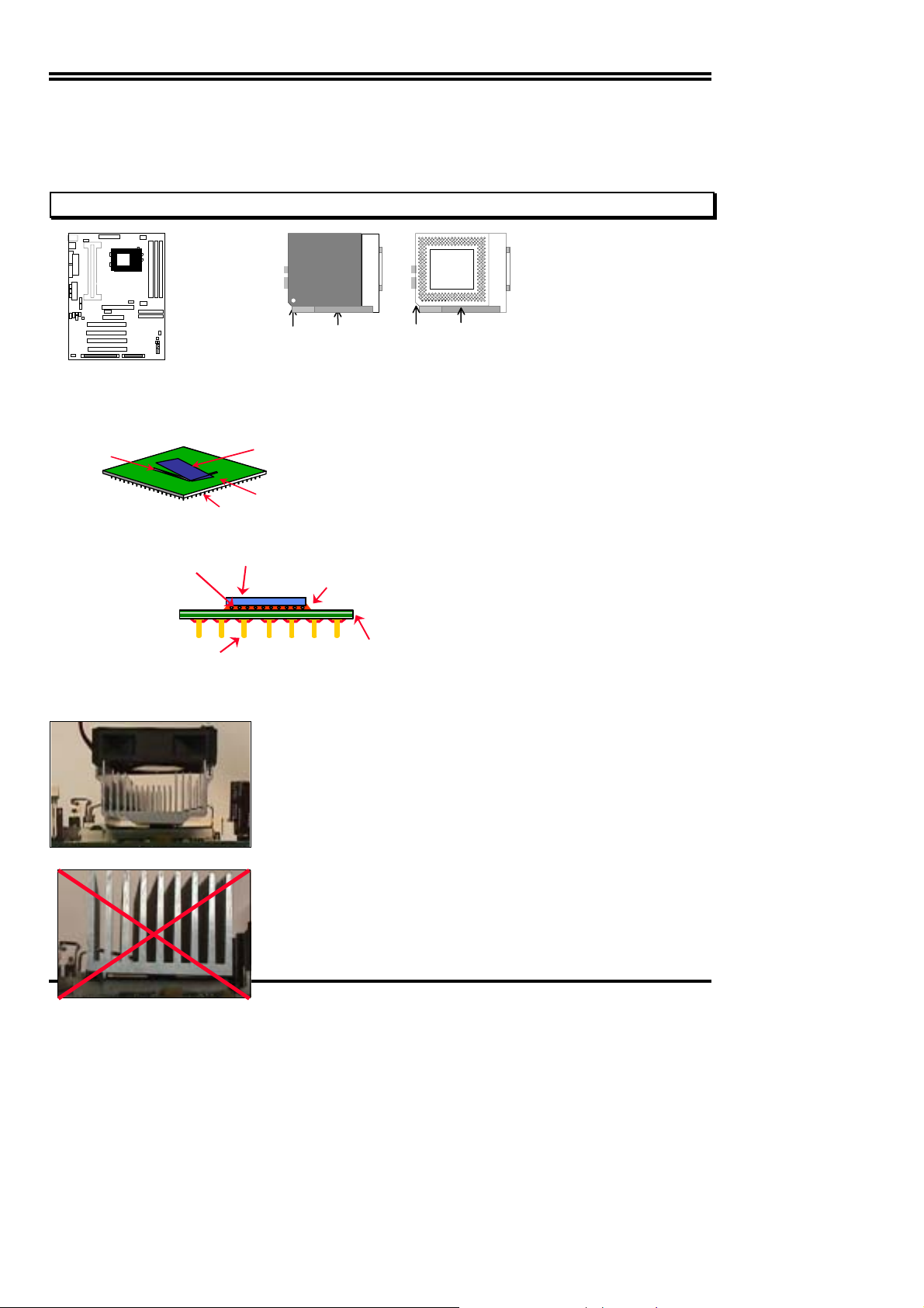
2-7-1 The mainboard provides a Slot-1 for Pentium II/III processor. The CPU on board must
have a fan or heat sink attached to prevent overheating.
WARNING: Without a fan or heat sink, the CPU will overheat and cause damage to both the CPU
To install a CPU, first turn off your system and remove its cover. Locate the Slot- 1 and place
RETENTION MODULE as following:
IMPORTANT: You must set jumper U19, U20 for “Bus Frequency Selection” and “CPU Ratio” on
1. Attach heat sink to the CPU.
2. Place Part A on Slot-1 and gently screw four corners on top of the main- board.
and the mainboard.
page6 depending on the CPU that you install.
PART A
2-7-2 The mainboard also provides a 370-pin ZIF Socket 370. The CPU on mainboard must
have a fan attached to prevent overheating.
To install a CPU, first turn off your system and remove its cover. Locate the ZIF Socket and
open it by first pulling the lever sideways away from the socket then upwards to a 90-degree
7
Page 10
right angle. Insert the CPU with the white dot as your guide. The white dot should point towards
the end of the level. The CPU has a corner pin for three of the four corners, the CPU will only fit
in the one orientation as shown as follow. With the added weight of the CPU fan, no f orce is
required to insert the CPU. Once completely inserted, hold down on the fan and close the
Socket’s lever.
IMPORTANT: You can setting the CPU ratio and Host Frequency in the BIOS setup on page 18
CPU
Socket 370
White Dot
2-7-3 Intel
The FC-PGA package has the processor’s silicon die directly mounted to a pinned interposer substrate.
The pin grid array is partially populated and there may be surface mount components in the unpopulated
central area of the pin field.
Fillet Epoxy
®
Pentium® III Processor (256K) in the FC-PGA form factor: Mechanical Features
Flip Chip Die
Lever
CPU ZIF Socket 370
Blank
Socket 370
Lock
(Not to scale)
Pins
Intel® Pentium® III Processor in the FC-PGA form factor: Mechanical Features
C4 Solder bumps
Surface mounted
pins
Reference Design: Heatsink
FC-PGA with the reference
design heatsink
Substrate
Flip-Chip Si Core
(Not to scale)
z Intel’s reference design thermal solution is an
active heatsink; an extruded aluminum heatsink
base and a fan attached to the top on the fi n
array.
• Hea tsinks for the PPGA will not work with th e
Fillet Epoxy
Multi-layer
substrate
FC-PGA. A pedestal is required on the
underside of the heatsink to clear the socket
z Recommended thermal interface
material: Chomerics* XTS454.
8
Page 11
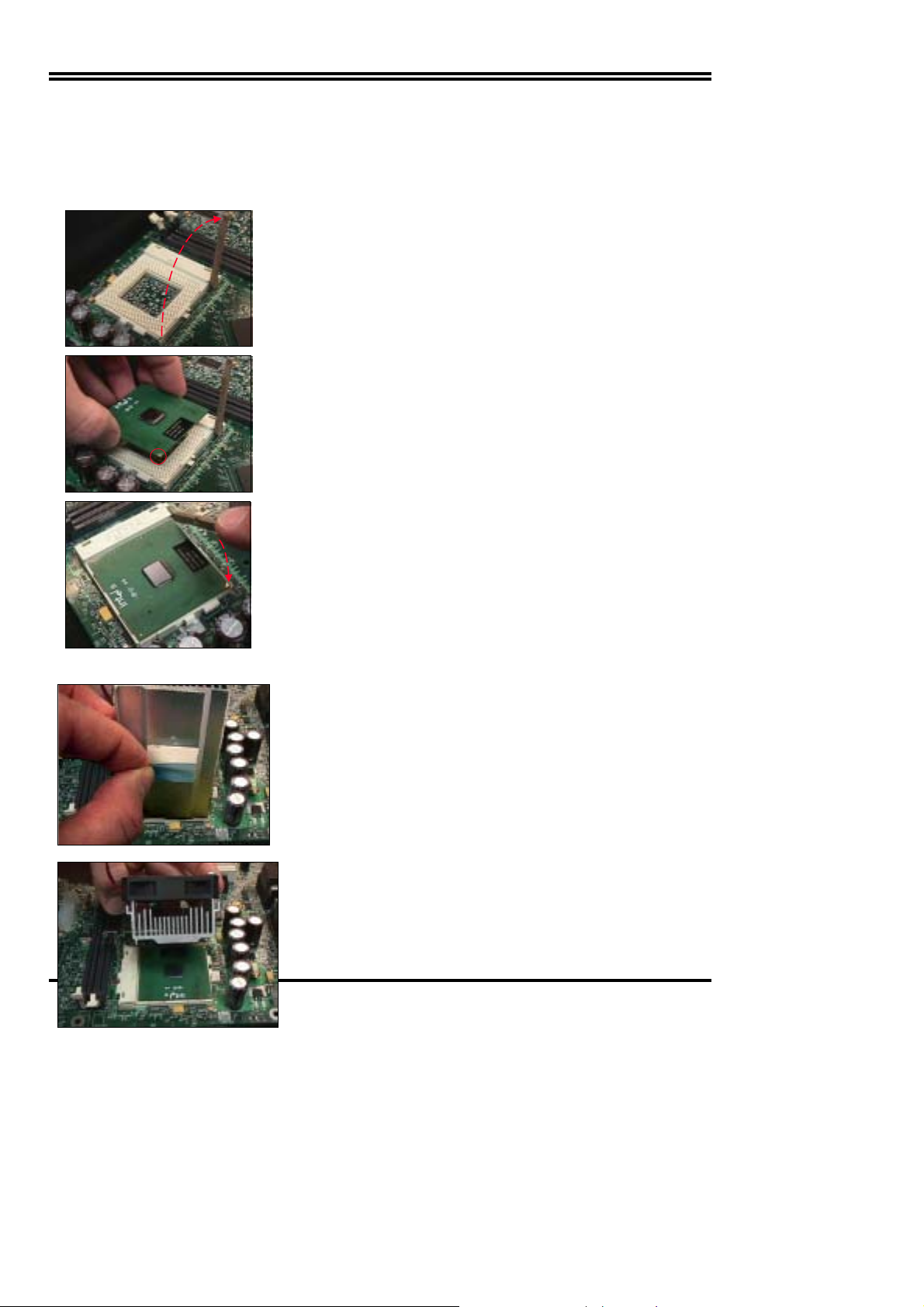
FC-PGA with a PPGA heatsink
CPU Insertion
Step 1
Open the socket by raising the actuation lever.
Step 2
Insert the processor.
Ensure proper pin 1 orientation by aligning the FC-PGA
corner marking with the socket corner closest to the
actuation arm tip. The pin field is keyed to prevent misoriented insertion.
Don’t force processor into socket. If it does not go in easily,
check for mis-orientation and debris.
Make sure the processor is fully inserted into the sock et
on all sides.
Step 3
Close the socket by lowering and locking the actuation lever.
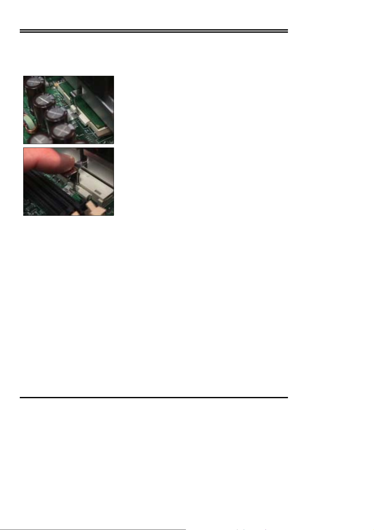
Heatsink A tt achme nt
Step 1
Remove the protective liner from the thermal interface
material on the underside of the heatsink.
This liner is not normally present on the Intel reference
active heatsink.
Step 2
Orient the heatsink with the keyed edge of
heatsink along the cam box side of the
processor.
The clip should be oriented so that the thumb tab will
engage on the cam box side of the socket.
Step 3
Seat the heatsink onto the processor and
engage the clip opposite from the cam box onto
9
Page 12
2-8 Expansion Cards
You must read the documentation come with expansion card for any hardware or software
settings that may be required to setup your specific card.
Installation Procedure:
1. Read the documentation from your expansion card.
2. Set any necessary jumpers on your expansion card.
3. Remove your computer’s cover.
4. Remove the bracket on the slot you intend to use.
5. Carefully align the card’s connectors and press firmly.
6. Secure the card on the slot with the screw you remove in step 4.
7. Replace the computer’s cover.
8. Setup the BIOS if necessary.
9. Install the necessary software drivers for your expansion card.
Assigning IRQs for Expansion Cards
Some expansion cards may require an IRQ to operate. Generally an IRQ must be exclusively
assigned to only one device. In an standard design there are 16 IRQs available but most of
them are occupied by the system and leaves 6 free for expansion cards.
With most recent device, the BIOS automatically assign an IRQ number to PCI expansion cards.
Please make sure there are no any of two devices use same IRQs, otherwise your computer
may experience some problems when those two devices are in use at the same time.
Assigning DMA Channels for Expansion Cards
10
Page 13
Some devices may also need to use a DMA (Direct Memory Access) channel. DMA
assignments for this mainboard are handled the same way as the IRQ assignment process
described above. You can select a DMA channel in the PCI and PnP configuration section of the
BIOS Setup utility.
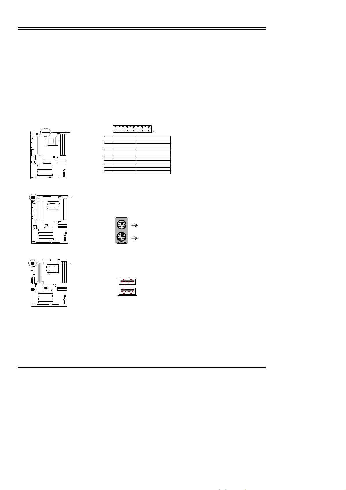
2-9 External Connectors
1. Power Connector: ATX Power Connector (20-pin block): PL1
ATX Power Supply connector. This is a new defined 20-pins connector that usually comes
with ATX case. The ATX Power Supply allows to use soft power on momentary switch that
connect from the front panel switch to 2-pins Power On jumper pole on the mainboard.
When the power switch on the back of the ATX power supply turned on, the full power will
not come into the system board until the front panel switch is mom entarily pressed. Press
this switch again will turn off the power to the system board.
PIN 1
PIN ROW2 ROW1
1 3.3V 3.3V
2 -12V 3.3V
3 GND GND
4 Soft Powe r O n 5 V
5 GND GND
6 GND 5V
7 GND GND
8 -5V Pow er OK
9 +5V +5VSB (for Soft Logic)
10 +5V +12V
2. PS/2 Mouse & PS/2 Keyboard Connector: MINI-DIN
The connectors for PS/2 keyboard and PS/2 Mouse.
ATX Power Connector
PS/2 Keyboard
3. USB Port connector: USB
The connectors are 4-pins connector that connect USB devices to the system board.
USB
USB Port C onn ector
4. Parallel Port Connector (25-pin female): PRINT
Parallel Port connector is a 25-pin D-Subminiature Receptacle connector. The On-board
Parallel Port can be disabled through the BIOS SETUP. Please refer to Chapter 3
“INTEGRATED PERIPHERALS SETUP” section for more detail information.
11
Page 14
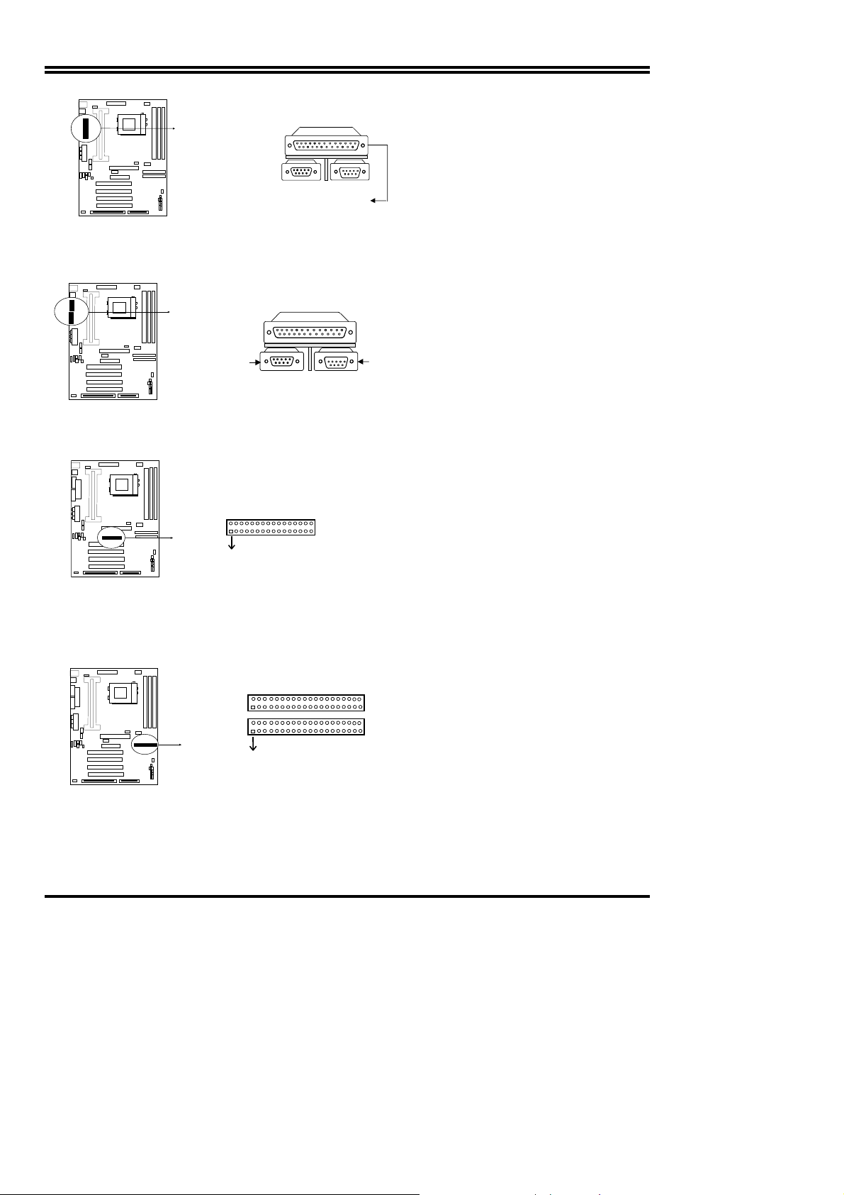
Parallel Port Connector
5. Serial Port COMA, COMB: COM1, COM2
COMA is the 9-pin D-Subminiature mail connector. The On-board serial port can be disabled
through BIOS SETUP. Please refer to Chapter 3 “INTEGRATED PERIPHERALS SETUP”
sec ti o n fo r m ore detail information.
COM1
6. Floppy drive Connector (34-pin block): F DD
Serial port COMA,COMB Connector
COM2
This con nector s u pports the pr ovi d ed floppy d riv e ribb on cable. After connecting the single plug
end to mainboard, connect the two plugs at other end to the floppy drives.
Pin 1
Floppy drive Connector
7. Primary IDE Connector (40-pin block): IDE1
This connector suppo rts the provided IDE hard disk ribbon ca ble. After c onnecting the single
plug end to mainboard, connect the two plugs at other end to your hard disk(s). If you install
two hard disks, you must configure the second drive to Slave mode by setting its jumpers
accordingly. Please refer to the documentation of your hard disk for the jumper settings.
Pin 1
Primary IDE Co nnecto r
8. Secondary IDE Connector (40-pin block): IDE2
This connector connects to the next set of Master and Slave hard disks. Follow the same
procedure described for the primary IDE connector. You may also configure two hard disks
12
Page 15

to be both Masters using one ribbon cable on the primary IDE connector and anoth er ribbon
cable on the secondary IDE connector.
Pin 1
Secondary IDE Connector
9. IDE activity LED: HDLED
This connector connects to the hard disk activity indicator light on the case.
HDLED
IDE (Hard Drive) L ED
10. SMI Switch : SMI
If your case has Suspend switch , you may connect the cable to this connector in order to
have Suspend mode control from your case.
SMI
SMI Switch
11. Turbo LED switch: TBLED
The mainboard‘s turbo function is always on. The turbo LED will remain constantly lit while
the system power is on. You may wish to connect the Power LED from the system case to
this lead. See the figure below.
12. Reset switch lead: RST
This 2-pin connector connects to the case-mounted reset switch for rebooting your computer
without having to turn off your power switch. This is a preferred method of rebooting in order
to prolong the life of the system‘s power supply. See the figure below.
13. Keyboard lock switch lead: KEYLOCK
This 5-pin connector connects to the case-mounted key switch for locking the keyboard for
security purposes. See the figure below.
14. Speaker connector: SPEAKER
This 4-pins connector connects to the case-mounted speaker. See the fi gure below.
13
Page 16

V
Turbo SW
Power LED
Lock
Keyboard
CC
GND
NC
GND
GND
GND
GND
NC
GND
VCC
Turbo LED
Reset SW
Speaker
System Case Connections
15. IR infrared module connector: IR1
This connector supports the optional wireless transmitting and receiving infrared module.
This module mounts to small opening on system cases that support this f eature you must
also configure the setting through BIOS setup. Use the four pins as shown on the Back View
and c on nect a r i b b o n ca b l e fr o m th e m od u l e to t h e mainboar d according to the pin definitions.
IR1
SIR
IR Infrared Module Connector
16. FAN connector: CPUFAN , SYSFAN
CPUFAN
SYSFAN
FAN Connector
17. Power-On button connector: PS-ON
Power-On bu tton connector
18. Wake On Lan connector: WOL
Push Button
GND
WOL
5VSB GND WON
4
2
14
Page 17

※
Wake On LAN Function worked only when power supply support 5VSB more than 750mA
current.
Jumpers & Connectors (Option for motherboard that emedded Audio chip)
19. On Board Audio chip Enabled / Disabled connector: JP4
2-3 closed: Enabled
1
3
JP4
1-2 closed: Disabled
1
3
20. Auxiliary Input connector: JP1
JP1
21. CD Audio in connector : JP2,JP3
JP2 and JP3 are the connectors for CD-Audio Input signal, Please connect it to CD-ROM
CD-Audio output connector
JP2 :CD-Adio/Panasonic
JP3
JP3 :CD-Audio/Sony
22. Audio and Game Connector : AGC
This Connector are 3 phone Jack for LINE-OUT,LINE-IN,MIC and a 15-pin
D-Subminiature Receptacle Connector for joystick/MIDI Device.
Line-out : audio output to speaker
Line-in : audio input to sound chip (Please plug here for second pair speakers as output
channels when use 4 speakers)
MIC : Microphone Connector
Game/MIDI : for joystick or MIDI Device
Game / MIDI P ORT
LINE-OUT MICLINE-IN
Audio and Game Connector
15
Page 18

23. PC Speaker signal Input connector: SPKIN 1
SPKIN 1
24. SPDIF (Sony / Philips Digital Interface) Input / Output Connectors: SPDIFIN 1 /
SPDIFOUT
SPDIFIN
GND
SPDIFIN 1
+5V
SPDIFOUT
SPDIFOUT
GND
25. Optical kit connector: JP9
This connector is for user that has Optical kit(optional) to provide other set of SPDIF
INPUT and SPDIF OUTPUT function.
JP 9
2
1
Optical kit Connector
10
9
Chapter 3
AWARD BIOS SETUP
This mainboard has previously set to its best stable status. If you are not an experienced user,
please do not change the default setting. When you are encounter any problem, please choice
“LOAD STANDARD DEFAULTS” t o restore best setting.
16
Page 19

Award’s ROM BIOS provides a built-in Setup program which allows user modify the basic system
configuration and hardware parameters. The modif ied data will be stored in a battery-backed
CMOS RAM so data will be retained even when the power is turned off. In general, the
information saved in the CMOS RAM stay unchanged unless here is configuration change in the
system, such as hard drive replacement or new equipment is installed.
It is possible that CMOS ha d a batt ery failure which cause data lose i n CM O S _ R A M . I f s o , r e - e n t e r
system configuration parameters become necessary.
To enter Setup Program
Power on the computer and press <Del> key immediately will bring you into BIOS CMOS
SETUP UTILITY
.
CMOS Setup Utility – Copyright ( C ) 1984-1999 Award Software
Standard CMOS Features
Advanced BIOS Features
Advanced Chipset Features
Integrated Peripherals
Power Management Setup
PnP/PCI Configurations
PC Health Status
Esc : QUIT F 9: Menu in BIOS
F10 : Save & Exit Setup
Frequency/Voltage Control
Load Optimal Defaults
Load Standard Defaults
Set Supervisor Password
Set User Password
Save & Exit Setup
Exit Without Saving
: Select Item
↑↓←→
Time, Date, Hard Disk Type….
Figure 3
Note that a brief description of each highlighted selection is listed below. The main menu
includes the following setup categories. Please recall that some systems may not include all
entries.
Standard CMOS Features: Use this menu for basic system configuration. See Section 3-1
for the details.
Advanced BIOS Features: Use this menu to set the Advanced Features available on your
system. See Section 3-2 for the details.
Advanced Chipset Features: Use this menu to change the values in the chipset registers
and optimize your system's performance. See section 3-3 for the details.
Integrated Periphera ls: Use this menu to specify your settings for integrated peripherals.
See section 3-4 for the details.
Power Mana gement Setup: Use this menu to specify your settings for power management.
See section 3-5 for the details.
PnP / PCI Configuration: This entry appears if your system supports PnP / PCI. See
section 3-6 for the details.
PC Health Status: Use this menu to show the temperature, FAN Speed, Voltage of the PC
Health. 3-7 for the details.
Frequency/Voltage Control: Use this menu to specif y your settings for frequency/voltage
control. See section 3-8 for the details.
17
Page 20

Load Optimal Defaults: Use this menu to load the Optimal default values for the higher
performance for your system to operate. See section 3-9 for the details.
Load Standard Defaults: Use this menu to load the BIOS default values that are factory
settings for normal/stable pe rformance system operations. While Award has designed the
custom BIOS to normal/stable performance, the factory has the right to change these
defaults to meet their needs. See section 3-10 for the details.
Supervisor / User Password: Use this menu to set User and/or Supervisor Passwords.
See section 3-11 for the details.
Save & Exit Setup: Save CMOS value changes to CMOS and exit setup. See section 3-12
for the details.
Exit Without Save: Abandon all CMOS value changes and exit setup. See section 3-12 for
the details.
3-1 STANDARD CMOS FEATURES
The items in Standard CMOS Features Menu are divided into many categories, and each category may
includes more than one setup items. Please use the arrow keys to highlight the item and then use the
<PgUp> or <PgDn> keys to select the value you want in each item.
CMOS Setup Utility-Copyright © 1984-1999 Award Software
Standard CMOS Features
Date: (mm:dd:yy) Fri, DEC 10 1999
Time: (hh:mm:ss) 10:52:22
IDE Primary Master Press Enter None
¾
IDE Primary Slave Press Enter None
¾
IDE Secondary Master Press Enter None
¾
IDE Secondary Slave Press Enter None
¾
Menu Level ¾
Change the day, month,
year and century
Drive A 1.44M, 3.5 in.
Drive B None
Video EGA/VGA
Halt On All Errors
Based Memory 640K
Extended Memory 60416K
Total Memory 61440K
↑↓←→Move Enter: Select +/-/PU/PD: Value F10:Save ESC: Exit F1:General Help
F5:Previous Values F6:Fail-Safe Defaults F7:Optimized Defaults
Figure 3-1
Item Help
IDE Adapters: The IDE adapters control the hard disk drive. Use a separate sub menu to
configure each hard disk drive. Diagram below shows the IDE primary master sub menu.
CMOS Setup Utility – Copyright © 1984-1999 Award Software
IDE Primary Master
18
Page 21

IDE HDD Auto-Detection Press Enter
IDE Primary Master Auto
Access Mode
Auto
Capacity 0 MB
0
0
0
0
0
Cylinder
Head
Precomp
Landing Zone
Sector
Menu Level ¾¾
To auto-detect the HDD’s size,
head... on this channel
Item Help
↑↓←→Move Enter: Select +/-/PU/PD: Value F10:Save ESC: Exit F1:General Help
F5:Previous Values
F6:Fail-Safe De faults F7:Optimized Defaults
Figure3-1-1 IDE Primary Master sub menu
Use the legend keys to navigate through this menu and exit to the main menu. Use Figure3-1-1
to configure the hard disk.
3-2 ADVANCED BIOS FEATURES
This section allows you to configure your system for basic operation. You have the opportunity
to select the system’s default speed, boot-up sequence, keyboard operation, shadowing and
security.
CMOS Setup Utility – Copyright © 1984 – 1999 Award Software
Advanced BIOS Features
Virus Warning Disabled
CPU Internal Cache Enabled
External Cache
CPU L2 Cache ECC Checking
Processor Number Feature
Quick Power On Self Test
First Boot Device
Second Boot Device HDD-0
Third Boot Device
Boot other Device Enabled
Swap Floppy Drive Disabled
Boot Up Floppy Seek Enabled
Boot Up NumLock Status Off
Gate A20 Option Fast
Typematic Rate Setting Disabled
X
Typematic Rate (Chars/Sec) 6
X
Typematic Delay (Msec) 250
Security Option
OS Select For DRAM > 64MB
HDD S.M.A.R.T. Capability Disabled
Enabled
Enabled
Enabled
Enabled
Floppy
LS/ZIP
Setup
Non-OS2
↑↓←→Move Enter: Select +/-/PU/PD: Value F10:Save ESC: Exit F1:General Help
F5:Previous Values F6:Fail-Safe Defaults F7:Optimized Defaults
Item Help
Menu Level ¾
Allows you to choose the VIR US
warning feature for IDE Hard Disk boot
sector protection. If thi s fun cti o n is
enabled and someone attempt to write
data into this area, BIOS will show a
warning messag e on screen and
alarm beep
Figure3-2
Virus Warning: Allow you choose the VIRUS W arning feature for the IDE Hard Disk boot
sector protection. If this function is enabled and someone attempts to write data into this
area, BIOS will show a warning message on screen and alarm beep.
19
Page 22

Enabled Activates automatically when the system boots up causing a
warning message to appear when anything attempts to access the
boot sector or hard disk partition table.
Disabled No warning message will appear when anything attempts to
access the boot sector or hard disk partition table.
CPU Internal Cache/External Cache: These two categories speed up memory access.
However, it depends on CPU/chipset design.
CPU L2 Cache ECC Checking: This item allows you enable/disable CPU L2 Cache ECC
checking.
The choice: Enabled, Disabled.
Quick Power On Self Test: This category speeds up Power On Self Test (POST) after you
power up the computer. If it is set to Enable, BIOS will shorten or skip some check items
during POST.
Enabled Enabl e quick POST
Disabled Normal POST
First/Second/T hird/O ther Boot Devi ce: The BIOS attempts to load the operating system from
the devices in the sequence selected in these items.
The Choice: Floppy, LS/ZIP, HDD, SCSI, and CDROM.
Other Boot Device: If this option is enable the Bios will attempt to load operating system from other
boot device that is available if the other fails.
Swap Floppy Drive: If the system has two floppy drives, you can swap the logical drive
name assignments.
The choice: Enabled/Disabled.
Boot Up Floppy Seek: Seeks disk drives during boot up. Disabling speeds boot up.
The choice: Enabled/Disabled.
Boot Up NumLock Sta tus: Select power on state for NumLock.
The choice: Enabled/Disabled.
Gate A20 Option: Select if chipset or keyboard controller should control GateA20.
Normal A pin in the keyboard controller controls GateA20
Fast Lets chipset control GateA20
Typematic Rate Setting: Key strokes repeat at a rate determined by the keyboard
controller. When enabled, the typematic rate and typematic delay can be selected.
The choice: Enabled/Disabled.
Typematic Rate (Chars/Sec): Sets the number of times a second to repeat a keystroke
when you hold the key down.
The choice: 6, 8, 10, 12, 15, 20, 24, 30.
Typematic Delay (Msec): Sets the delay time after the key is held down before it begins to
repeat the keystroke.
The choice: 250, 500, 750, 1000.
Security Option: Select whether the password is required every time the system boots or
only when you enter setup.
System The system will not boot and access to Setup will be denied if the
correct password is not entered at the prompt.
20
Page 23

Setup The system will boot, but access to Setup will be denied if the
correct password is not entered at the prompt.
Note: To disable security, select PASSWORD SETTING at Ma in Menu and then you will be
asked to enter password. Do not type anything and just press <Enter>, it will disable security.
Once the security is disabled, the system will boot and you can enter Setup freely.
OS Select For DRAM > 64MB: Select the operating system that is running with greater
than 64MB of RAM on the system.
The choice: Non-OS2, OS2.
Report No FDD For Win 95: Whether report no FDD for Win 95 or not.
The choice: Yes, No.
3-3 ADVANCED CHIPSET FEATURES
This section allows you to configure the system based on the specific features of the installed chipset.
This chipset manages bus speeds and access to system memory resources, such as DRAM and the
external cache. It also coordinates communications between the conventional ISA bus and the PCI bus.
It must be stated that these items should never need to be altered. The default settings have been
chosen because they provide the best operating conditions for your system. The only time you might
consider making any changes would be if you discovered that data was being lost while using your
system.
CMOS Setup Utility – Copyright © 1984 – 1999 Award Software
Advanced Chipset Features
Bank 0/1 DRAM Timing SDRAM 10ns
Bank 2/3 DRAM Timing SDRAM 10ns
Bank 4/5 DRAM Timing SDRAM 10ns
SDRAM Cycle Length 3
DRAM Clock Host CLK
Memory Hole Disabled
P2C/C2P Concurrency
Fast R-W Turn Around
Enabled
Disabled
System BIOS Cacheable Enabled
Video RAM Cacheable
AGP Aperture Size
AGP Mode Select
Enabled
64MB
4X
AGP Drive Strength 0ECH
OnChip USB
USB Keyboard Support
CPU to PCI Write Buffer
PCI Dynamic Bursting
PCI Master 0 WS Write
PCI Delay Transaction
Enabled
Enabled
Enabled
Disabled
Enabled
Disabled
↑↓←→Move Enter: Select +/-/PU/PD: Value F10:Save ESC: Exit F1:General Help
F5:Previous Values F6:Fail-Safe Defaults F7:Optimized Defaults
Figure 3-5
DRAM Timings: These settings deal with CPU access to dynamic random access memory (DRAM).
The default timings have been carefully chosen and should only be altered if data is being lost. S uch
a scenario might occurs if your system had mixed speed DRAM chips i nst alled so that greater delays
may be required to preserve the integrity of the data held in the slower memory chips.
AGP Mode Select: This function allows you choose suitable AGP mode.
The Choice: 1X, 2X, 4X AGP mode.
21
Item Help
Menu Level ¾
Page 24

Delay Transaction: The chipset has an embedded 32-bit posted write buffer to support delay
transactions cycles. Select Enabled to support compliance with PCI specification version 2.1.
The Choice: Enabled, Disabled.
3-4 INTEGRATED PERIPHERALS
The “INTEGRATED P ERIPHERALS” section ma inly deals with I/O functio n. These fun ctions will
be necessary only when the system I/O malfunctioned or the system is unable to detects your
CD-ROM or hard disk.
CMOS Setup Utility – Copyright © 1984-1999 Award Software
Integrated Preipherals
OnChip IDE Channe10 Enabled
OnChip IDE Channel1
IDE Prefetch Mode
Enabled
Enabled
Primary Master PIO Auto
Primary Slave PIO Auto
Secondary Master PIO
Secondary Slave PIO
Auto
Auto
Primary Master UDMA Auto
Primary Slave UDMA Auto
Secondary Master UDMA
Secondary Slave UdMA
Auto
Auto
Init Display First PCI Slot
IDE HDD Block Mode Enabled
Onboard FDC Controller
Enabled
Onboard Serial Port 1 Auto
Onboard Serial Port 2 Auto
UR2 Mode Normal
UR2 Duplex Mode Disabled
Half Duplex time-out
Enabled
↑↓←→Move Enter: Select +/-/PU/PD: Value F10:Save ESC: Exit F1:General Help
F5:Previous Values F6:Fail-Safe Defaults F7:Optimized Defaults
Figure 3-4
OnChip IDE Channel 0/Channel 1: The integrated peripheral controller contains an IDE
interface with support for two IDE channels. Select Enabled to activate each channel
separately.
The choice: Enabled, Disabled.
IDE Primary/Secondary Master/Slave PIO: The four IDE PIO (Programmed Input/Output)
fields let you set a PIO mode (0-4) for each of t he four IDE devices that the onboard IDE
interface supports. Modes 0 through 4
mode, the system automatically determines the best mode for each device.
The choice: Auto, Mode 0, Mode 1, Mode 2, Mode 3, Mode 4.
Init Display First: This item allows you decide to active whether PCI Slot or AGP VGA first.
The choice: PCI Slot, AGP.
Onboard FDC Controlle r: Select Enabled if your system has a floppy disk controller (FDC)
installed on the system board and you wish to use it. If you install and-in FDC or the system
has no floppy drive, select Disabled in this field.
The choice: Enabled, Disabled.
provide successively increased performance. In Auto
Item Help
Menu Level ¾
22
Page 25

Onboard Serial Port 1/Port 2 : Select an address and corresponding interrupt for the first
and second serial ports.
The choice: 3F8/IRQ4, 2E8/IRQ3, 3E8/IRQ4, 2F8/IRQ3, Disabled, Auto.
3-5 POWER MANAGEMENT SETUP
The Power Management Setup allows you to configure you system to most eff ectively save energy while
operating in a manner consistent with your own style of computer use.
CMOS Setup Utility – Copyright © 1984 – 1999 Award Software
Power Management Setup
ACPI function Enabled
¾Power Management Press Enter
PM Control by APM
Video Off Option
Video Off Method
MODEM Use IRQ
Soft-off by PWRBTN
Yes
Suspend -> Off
V/H SYNC+Blank
3
Instant-off
¾Wake Up Events Press Enter
↑↓←→Move Enter: Select +/-/PU/PD: Value F10:Save ESC: Exit F1:General Help
F5:Previous Values F6:Fail-Safe Defaults F7:Optimized Defaults
Figure 3-5
ACPI Function:
and Power Management (ACPI). (Please refer to page 42 for installation procedure)
The choice: Enabled, Disabled.
This item allows you to enable/disable the Advanced Configuration
Power Management: This category allows you to select the type (or degree) of power
saving and is directly related to the following modes:
1. HDD P ower D own
2. Doze Mode
3. Suspend Mode
There are four selections for Power Management, three of which have fixed mode settings.
Disable (default) No power management. Disables all four modes
Min. Power Saving Minimum power management. Doze Mode = 1 hr. Standby Mode =
1 hr., Suspend Mode = 1 hr., and HDD Power Down = 15 min.
Max. Power Saving
Maximum power management --
CPU’s
. Doze Mode = 1 min., Standby Mode = 1 min., Suspend
Mode = 1 min., and HDD Power Down = 1 min.
User Defined Allows you to set each mode individually. When not disabled, each
of the ranges are from 1 min. to 1 hr. except for HDD Power Down
which ranges from 1 min. to 15 min. and disable.
Video Off Method: This determines the manner in which the monitor is blanked.
V/H SYNC+Blank This selection will cause the system to turn off the vertical and
horizontal synchronization ports and write blanks to the video buffer.
Blank Screen This option only writes blanks to the video buffer.
DPMS Initial display power management signaling.
Video Off In Suspend : This determines the manner in which the monitor is blanked.
The choice: Yes, No.
Item Help
Menu Level ¾
ONLY AVAILABLE FOR SL
23
Page 26

Suspend Type: Select the Suspend Type.
The choice: PWRON Suspend, Stop Grant.
MODEM Use IRQ: This determines the IRQ in which the MODEM can use.
The choice: 3, 4, 5, 7, 9, 10, 11, NA.
Suspend Mode: When enabled and after the set time of system inactivity, all devices
except the CPU will be shut off.
The choice: Enabled, Disabled.
HDD Power Down: When enabled and after the set time of system inactivity, the hard disk
drive will be powered down while all other devices remain active.
The choice: Enabled, Disabled.
Soft-Off by PWRBTN: Pressing the power button for more than 4 seconds forces the
system to enter the Soft-Off state when the system has “hung.”
The choice: Delay 4 Sec, Instant-Off.
Power on by ring :
state.
Resume on by alarm : When you select Enabled, the system will wake up from suspend mode as
defined in Resume Time.
The choice: Enabled, Disabled.
When you select Enabled, a signal fr om ring returns the system to Full On
3-6 PnP/PCI CONFIGURATION SETUP
This section describes configuring the PCI bus system. PCI, or Personal Computer Interconnect, is a
system which allows I/O devices to operate at speeds nearing the speed the CPU itself uses when
communicating with its own special components. This section covers some very technical items and it is
strongly recommended that only experienced users should make any changes to the default settings.
CMOS Setup Utility – Copyright © 1984-1999 Award Software
PnP/PCI Configurations
PNP OS Installed NO
Reset Configuration Data Disabled
Resources Controlled By Manual
¾IRQ Resources
Press Enter
¾DMA Resources Press Enter
PCI/VGA Palette Snoop
Assign IRQ For VGA
Assign IRQ For USB
↑↓←→ Move Enter: Select +/-/PU/PD: Value F10:Save ESC: Exit F1:General Help
F5:Previous Values F6:Fail-Safe Defaults F7:Optimized Defaults
PnP OS Installed:
The choice: Yes, No.
This item allows you to determine installed PnP OS or not.
Disabled
Enabled
Enabled
Figure 3-6
Reset Configuration Data: Normally, you leave this field Disabled. Select Enabled to reset
Extended System Configuration Data (ESCD) when you exit Setup if you have installed a
new add-on and the system reconfiguration has caused such a serious conflict that the
operating system can not boot.
The choice: Enabled, Disabled .
Resource controlled by: Auto will allow the Award Plug and Play BIOS to automatically
configure all of the boot and Plug and Play compatible devices. If you have trouble in
24
Item Help
Menu Level ¾
Select Yes if you are using
A Plug and Play capable
operating system Select
No if you need the BIOS to
Configure non-boot devices
Page 27

assigning the interrupt resource automatically you can select “manual”, it will allow you to
choose specific resources by going into each of the sub menu that follows this field (a sub
menu is preceded by a “¾”).
The choice: Auto(ESCD), Manual .
IRQ Resources:
depending on the type of device using the interrupt.
IRQ3/4/5/7/9/10/11/12/14/ 15 assigned to:
ISA bus and is not available to any PCI slot. Legacy ISA for devices compliant with the original PC
AT bus specification, PCI/ISA PnP for devices compliant with the Plug and Play standard whether
designed for PCI or ISA bus architecture.
The Choice: Legacy ISA and PCI/ISA PnP.
DMA Resources: When resources are controlled manually, assign each system DMA channel a
type, depending on the type of device using the DM channel.
DMA 0/1/3/5/6/7 assigned to:
specification, PCI/ISA PnP for devices compliant with the Plug and Play standard whether designed
for PCI or ISA bus architecture.
Choices are Legacy ISA and PCI/ISA PnP.
PCI/VGA Palette Snoop:
When resources are controlled manually, assign each system interrupt a type,
This item allows you to determine the IRQ assigned to the
Legacy ISA for devices compliant with the original PC AT bus
Leave this field at Disabled.
Choices are Enabled, Disabled.
3-7 PC HEALTH STATUS
CMOS Setup Utility – Copyright © 1984-1999 Award Software
PC Health Status
CPU Warning Temperature Disabled
Current System Temp. 25ºC
Current CPU Temperature 50ºC
Current CPUFAN Speed 4200
Current SYSFAN Speed
4200
Vcore 2.0
+3.3V
+ 5 V
+12V
-12V
3.3
5.1
12.1
-11.98
Shutdown Temperature Disabled
↑↓←→ Move Enter: Select +/-/PU/PD: Value F10:Save ESC: Exit F1:General Help
F5:Previous Values F6:Fail-Safe Defaults F7:Optimized Defaults
Figure 3-7
CPU Warning Temperature: this item is to setting the Max. Temperature of CPU bef ore it will
have warning alarm.
Shutdown Temperature: this item is to setting the temperature for system shutdown , the
。
choice: from 60
C to 90。C
Item Help
Menu Level ¾
3-8 FREQUENCY/VOLTAGE CONTROL
CMOS Setup Utility – Copyright © 1984-1999 Award Software
Frequency/Voltage Control
25
Page 28

Auto Detect DIMM/PCI Clk Enabled
Spreed Spectrum
Disabled
CPU Host/PCI Clock Default
Item Help
Menu Level ¾
↑↓←→ Move Enter: Select +/-/PU/PD: Value F10:Save ESC: Exit F1:General Help
F5:Previous Values F6:Fail-Safe Defaults F7:Optimized Defaults
Figure 3-8
DIMM/PCI CLK: This item allows you to enable/disable auto detect DIMM/PCI Clock.
The choice: Enabled, Disabled.
Spread Spectrum: This item allows you to choice CPU clock/Spread Spectrum (ON,OFF)
(66MHz,75MHz……..) enable/disable the spread spectrum modulate.
The choice: Disabled (the CPU clock Depend on Jumper), 0.25%, 0.05%.
CPU Host/PCI Clock: In this item you can choose the CPU HOST/PCI Clock. The setting
are: Default ,66/33,75/37,83/41,100/33,103/34, 112/37,124/41, 124/31,133/33,133/44,
140/35. IF the setting is ”default” , CPU HOST Clock will depend on the setting of U19.
If U19 is set to 66MHz, you have only the choice of 66/33, 75/37, 83/41 on screen.
If U19 is setting to 100MHz, you can have 100/33,103/34,112/37,124/41, 124/41.
If U19 is setting to 133MHz, you have the choice: 133/33,133/44,140/35.
*Please turn off system power if the screen does not have any display after change of the
setting. Then press and hold down “ INS ” key, and turn on system power again (release
“ INS ” key till the screen has display) to reset correct f requency of CPU HOST clock.
3-9 LOAD OPTIMAL DEFAULTS
Load Optimal Defaults:
When you press <Enter> on this item you get a confirmation dialog box with a message
similar to:
Load Optimal Defaults (Y/N) ? N
Pressing ‘Y’ loads the Optimal default values for the most stable, optimal performance
system operations.
3-10 LOAD STANDARD DEFAULTS
Load Standard Defaults:
When you press <Enter> on this item you get a confirmation dialog box with a message as:
Load Standard Defaults (Y/N) ? N
Pressing ‘Y’ loads the Standard default values that are factory settings for normal
performance system operations.
3-11 SUPERVISOR/USER PASSWORD SETTING
In this section you can set either supervisor or user password, or both of then.
26
Page 29

supervisor password :
user password
function, the following message will appear at the
center of the screen to assist you in creating a password.
ENTER PASSWORD:
Type the password, up to eight characters in length, and press <Enter>. The password typed now will
clear any previously entered password from CMOS memory. You will be asked to confirm the password.
Type the password again and press <Enter>. You may also press <Esc> to abort the selection and not
enter a password.
To disable a password, just press <Enter> when you are prompted to enter the password. A message
will confirm the password will be disabled. Once the password is disabled, the system will boot and you
can enter Setup freely.
PASSWORD DISABLED.
When a password has been enabled, you will be prompted to enter it every time you try to enter Setup.
This prevents an unauthorized person from changing any part of your system configuration.
Additionally, when a password is enabled, you can also require the BIOS to request a password every
time your system is rebooted. This would prevent unauthorized use of your computer.
You determine when the password is required within the BIOS Features Setup Menu and its Security
option (see Section 3). If the Security option is set to “System”, the password will be required both at
boot and at entry to Setup. If set to “Setup”, prompting only occurs when trying to enter Setup.
: just can only enter but do not have the right to change
can enter and change the options of the setup menus.
the options of the setup menus. When you select this
3-12 EXIT SELECTING
Save & Exit Setup
Pressing <Enter> on this item asks for confirmation:
Save to CMOS and EXIT (Y/N)? Y
Pressing “Y” stores the selections made in the menus in CMOS – a special section of memory
that stays on after you turn your system off. The next time you boot your computer, the BIOS
configures your system according to the Setup selections stored in CMOS. After saving the
values the system is restarted again.
Exit Without Saving
Pressing <Enter> on this item asks for confirmation:
Quit without saving (Y/N)? Y
This allows you to exit Setup without storing in CMOS any change. The previous selections
remain in effect. This exits the Setup utility and restarts your computer.
Chapter 4
4-1 Mainboard Driver Install in Win9X,WinNT
To install the mainboard driver please run
X:\VIA\Driver\SETUP.EXE.
After execute Setup .EXE the screen will depend on the OS (Operating System) to show the
necessary Driver which you have to install in your system, such like IDE Driver, AGP VXD
Driver, VIA chipset Feature Registry and IRQ Routing Miniport Driver . Follow the procedure
to install the driver.
27
Page 30

We recommend to install all the Driver which this utility show in Screen ,because it will
increase the system performance and solve the compatibility problem between system
chipset and other device.
For Example , You have to install this driver before you install AGP VGA driver otherwise it
can’t install your VGA Driver succeed.
4-2 PC HEALTH MONITOR-III (option for motherboard that embedded
PC Health) Software for Windows 95/98
Please Run X:\VIA\HEALTH3\SETUP.EXE
NOTES 1. For Windows 95 user:You must run SETUP.EXE twice in order to
complete this installation. The computer will install device
identification at first time when you run SETUP.EXE. When you
finish, you need re-start your computer manually and run
SETUP.EXE once again to install correspond driver.
2. Please follow on screen instruction to complete your installation.
3. Please refer to HELP for Windows 95/98 related questions.
28
Page 31

General Description
The PC HEALTH MONITOR-III Software, an application software based on Microsof t Wind o ws 95 ,
is used to control the PC HEALTH MONITOR CHIP. It can monitor the temperatures, power
supply voltages and fan speeds via PC HEALTH MONITOR CHIP and show the information on
screen periodically. User can use it to specify temperature, voltage and fan speed configurations
used by monitor chip. By the way, the alarm warning events and polling interval could also be set
by this software. If there is an abnormal event happens, it will pop up a window on screen to
inform the user the abnormal situation.
Using the Software
註解
:
General Function
1. Power Supply Voltage :
VCORE Low Limit/High Limit
3.3V Low Limit/High Limit
+5V Low Limit/High Limit
+12V Low Limit/High Limit
-12V Low Limit/High Limi t
These values are used to specify the threshold values of detecting the abnormal condition of ,
3.3V, +5V, +12V, -12V.
2.
FAN Speed
CPUFAN/ SYSFAN
If the fan RPM is lower than this value and “CPUFAN/SYSFAN” is enabled in Monitoring
Config. the PC Speaker will alarm and the mo nitor software will pop up a window to inform
user.
Temperature
3.
System/ CPU Low Limit/ High Limit
29
Page 32

There values is used to specify the Temp-Over register/ Tem-under register of PC HEALTH
MONITOR CHIP, If the temperature of the external thermistor is higher than this value and
“System/CPU” is enabled in Monitoring Config. the monitor software will pop up a window to
inform user.
Monitoring Config.
Enabled or Disabled: User can decide which item should be monitored or not by choosing the
item in the configuration page.
Faults Count (1 or 3): User can decide the system to pop up the warning message when there
is 1 fault detected or there are 3 consecutive faults detected.
Beep: In addition to pop up warning message user can choose to activate Beep
tone if there is error detected. Beep tone will until the error is treated.
4-3 Sound Driver & Audio Rack Installation( Option for Motherboard
That Embedded Audio Chip ) :
Special Features for CMI8738 audio chip
PCI Plug and Play (PnP) bus interface, 32 bit PCI bus master.
Full duplex playback and recording, built-in 16 bits CODEC.
HRTF 3D positional audio, supports both Direct Sound 3D® & A3D® interfaces, supports
earphones, two and four channel speakers mode.
Support Windows 3.1 / 95 / 98 and Windows NT 4.0.
Built-in 32 OHM Earphone buffer and 3D surround.
MPU-401 Game/Midi port and legacy audio SB16 support.
Downloadable Wave Table Synthesizer, supports Direct Music®.
• Digital Audio (SPDIF IN/OUT)
Up to 24 bit stereo 44KHz sampling rate voice playback/recording.
30
Page 33

Full duplex playback and recording, 120dB audio quality measured.
Auto detectable SPDIF/IN signal level from 0.5V to 5V.
• Stereo Mixer and FM Music Synthesizer
Stereo analog mixing from CD-Audio, Line-in
Stereo digital mixing from Voice, FM/Wave-table, Digital CD-Audio
Mono mixing from MIC and software adjustable volume
OPL3 FM synthesizer (4 operators)
Up to 15 melody sounds and 5 rhythm sounds (20 voices)
• Game and Midi Interface
Fully compatible with MPU-401 Midi UART and Sound Blaster Midi
mode/ Standard IBM PC joystick/game port (dual channels)
DOS Installation
Before beginning the installation, please make sure that your hard disk has sufficient space(min.
4MB). Insert the Driver CD into the CD-ROM Drive.
1. Change directory to PCI audio DOS drivers folder (ex. X:\CMI8738\DOSDRV) at DOS prompt,
and type:
INSTALL [Enter]
2. Type DOS utilities path which you want to install.
3. Program will expand the file to the path which you've specified.
4. Install program will add initial drivers into AUTOEXEC.BAT file.
Win95/98 Installation
We recommend that you install Microsoft W indows before you install this PCI sound card,
and you not install any other sound card device drivers in your current system.
1. Turn on the computer , and enter the Microsoft Windows 95/98
2. Bef ore install sound card driver please double-click “My Computer” icon, “Control Panel” icon ,
“System” icon, and choose “Device Manager” item.
3. Check “Other Device” item ,if there have “PCI Multimedia Audio Device”, please remove it
first ,and Restart System again.
4. You will see a windows prompt like this:
“New Hardware Found PCI Multimedia Audio Device Windows has found new hardware and
is installing the software for it” , then the dialog box shown Click “Next” button to go on.
5. Click “Other Locations” button to specify drivers path:
“ X:\CMI8738\Win9X\DRV”
6. Select “OK” to finish install.
7. Now, system is installing device drivers automatically. After a while, the system will finish the
installation includes the following device drivers.
CMI8738/C3DX PCI Audio Device
CMI8738/C3DX PCI Audio Joystick Device
CMI8738/C3DX PCI Audio Legacy Device
DOS mode MPU-401 Emulator
8. Install Application Software : Click “start” key
9. Select “Run”
10. Key in the drive and path for Windows application installation program, for example,
31
Page 34

in Win95 “X:\CMI8738\Win9X\APP\Win95\SETUP.EXE”
in Win98 “X:\CMI8738\Win9X\APP\Win98\SETUP.EXE”
11. Click “OK” to start the installation procedure, and follow the on-screen instructions to finish
the installation. When all the application softwares have been installed, please shut down
Windows 95/98 system, and reboot your system.
Win95/98 Un-Installation
If you install Win95/98 and a sound card at the same time, you might experience some
technical difficulties(the device might not function properly). It is suggested that you proceed
with the un-install procedure:
1. Click "start" button.
2. Select "run" item.
3. Find UINSTDRV.EXE in driver disk under Win95/98 drivers folder.
4. Run it.
5. Follow the on-screen instructions to re-install the hardware.
If you want to completely remove the drivers, you can also run the un-install procedure as
described previously. Remove the sound card from the slot, and then reboot the system.
Windows NT 4.0 Installation
We recommend that you install Windows NT 4.0 before you install this PCI audio card, and you
not install any other sound card device drivers in your current system.
1. Click “Start” button, move the highlight bar to “Setting” item, and select the “Control Panel”.
2. Double-click “Multimedia” icon.
3. Select “Devices” page, and press “Add” button.
4. Select “Unlisted or Updated Driver” item in “List of Drivers”.
5. Specify the drive and the path where NT drivers are in (such as X:\CMI8738\NT40\DRV).
6. Select “C-Media CM8738” item and press “OK” button.
7. Select proper I/O value.
8. Press “OK” button.
9. Restart the system when being asked.
10. Now, you have already installed the PCI Audio Adapter under Microsoft Windows NT 4.0
successfully. if you want to install the Windows applications, continue the following steps:
11. Click “start” key.
12. Select “Run” item.
13. Key in drive and path for Windows NT application installation program, for example,
“X:\CMI8738\NT40\APP\SETUP.EXE”
14. Click “OK” to start the installation procedure, and follow the on-screen instructions to finish
the installation. When all of application softwares have been installed, shut down the
Windows NT system, and then reboot your system.
Windows Appc. (The Audio Rack)
Introduction
By means of a user-friendly interface(as easy as operating your home stereo system), this PCI
audio rack provides you with the control over your PC’s audio functions, including the advantage
of four speakers mode enable/ disable, and perfect digital sound ( SPDIF ) input / output control.
32
Page 35

This Audio Rack consists of several major components:
Control Center: Controls the display of the PCI Audio Rack’s components.
MIDI Player: Plays MIDI music files, and allows you to create your personal song playlists, and
play the song files.
Wave Player: Records and plays digital audio (wave) files. Allows you to create wave file
playlists, and playback the wave files.
CD Player: Plays standard audio CDs. Allows you to create your favorite song playlists.
System Mixer: Controls the volume level of your audio inputs and outputs.
Showing or Hiding Audio Rack Components
To remove or add a component from the display, click on the component's button on the Control
Center’s Button Bar or toggle it off.
MIDI Player, Wave Player, and CD Player
CD Player (above, similar to Wave Player and MIDI Player)
Sel (or Trk) field: If you have multiple selections in your playlist, this shows the number of the
current selection or CD track.
Current File or Track: The name of the current MIDI file, wave audio file, or CD track.
Total Length field: displays the total length of files or tracks in minutes and seconds.
Current Time field: displays the current time of files or tracks in m inutes and seconds when
playback or recording.
Please refer to the help screen for more detail button function descriptions. (click on help “
”
button on the player)
System Mixer
System Mixer allows you to control all the audio output and input levels.
System Mixer displays the volume controls which your audio drivers make available. The names
for these controls may vary.
33
Page 36

Mixer panel while the four speakers mode is enabled.
Mixer panel while the four speakers mode is disabled.
Volume Control: Clicking on this button shows and allows you to use the output level controls.
Recording Control: Clicking on this button shows and allows you use the input level controls.
Input and Output Level Sliders and Bu ttons
: For each input or output signal type, the control
slider controls the loudness whereas the horizontal slider controls the balance between the two
speakers. The mute button temporarily stops input or output without changing slider positions.
Control types and names might vary. The common types are listed below:
Vol: The master control for all outputs. The strength of an output signal is determined by both
•
the Vol slider and the slider for the individual output. To affect all outputs, move the Vol slider.
To change the output of an individual output type, move its slider.
Line-in/Rear: Controls the audio hardware's Line In or Line Out levels. Line levels might be for
•
an externally attached cassette player, for instance, while the four speakers mode is enabled,
this control becomes the Rear speaker volume control.
Mic: Controls the microphone input level.
•
Wave: Controls wave (voice) playback or the recording levels.
•
FM: Controls the FM music playback or the recording level.
•
Aux-in: Controls the Aux-in music play or the recording level.
•
PC-SPK: Controls the external PC speaker input level.
•
CD: Controls the CD drive output level, for CD drives configured to play their audio output
•
through the PC’s audio hardware.
4SPK: Turn on or turn off the Rear speakers effect.
•
Surround: Turn on or turn off the 3D surround sound ef fect.
•
SPDIF-in: Turn on or turn off the SPDIF digital signal input.
•
•
Advanced: Check the SPDIF status, HRTF 3D sound CPU Utilization, turn on th Microphone
Booster.
Mute Buttons
: Toggle between muting and enabling the signal. A button with a lit LED is
34
Page 37

enabled, and when it is not lit, it means it is m ute. Several output signals can usually be enabled
at once.
MP3 Player : MP3 player can play both wave files and MP3 files.
MP3 player while the loop function enables.
The settings’ window while one of the SPDIF functions is enable.
The 4 Speakers System
This Audio Adapter provides 2 wave channels(front/rear), known as the 4 speakers system.
When games or application programs via DirectSound® 3D or A3D® interface locate the sound
sources to the listener's back, the two rear speakers will work to enhance the rear audio
positional effect, so as to complement the insufficiency of using only two front speakers to
emulate the audio effect. The following is the hardware installation and the software setups:
1. The speaker installation.
Connect the front pair speakers to the Line-out jack of the audio adapter, and then connect rear
pair speakers to Line-in/Rear jack of the audio adapter. The original Line-in can be moved to
Aux-in.
2. The positions of the speakers
Put your speakers the way the following picture suggests, so as to avail yourself to the best
audio result.
3. The mixer setup
There is a 4 speakers option in the volume control of the mixer, and when you enable this option,
it means the rear speakers are connected to Line-in/Rear jack. When Line-in/Rear jack is
connected to other external Line-in sources, please DO NOT enable this option in order to avoid
hardware conflicts. Regarding rear speaker option, you can turn on or turn off the output of the
back speakers, and adjust the volume, to have the rear/front speakers have the same volume.
4.The demo
35
Page 38

Execute the "Helicopter" demo within the C3D HRTF Positional Audio Demos of this audio
adapter. When the helicopter flies behind you, the rear speakers will work.
Optical Kid for SPDIF/OUT (Option for motherboard that embe dded PC Health chip)
The Optical Kid includes:
z Optical Module
z Optical Cable
z Software DVD driver
DIP-SWITCH
OPTICAL OUT
OPTICAL IN
J1:SPDIF-IN
An example of optical kit with MD connection.
The application program setup(please install CMI8738 application program first)
When the connection is done, please go to the Start menu and select PCI Audio
Applications\Audio Environment Setting
36
Page 39

When all the procedures have been c ompleted, there will be an infrared signal coming from the
SPDIF/OUT of the optical fiber of the sound card.
37
Page 40

Please note that signal beam may cause severe damage to the eyes. For your safety,
please point the output end to a piece of white paper to check if thebeam is in function
.
Please connect the output signal to the MD input, then play the music via the MP3 player.
38
Page 41

Please note that in playback, if there is no gap longer than three seconds between each track, the
MD can not recognize the tracks and w ill record all of them i nto one. It is recommended that you
set the gap time to 3~5 seconds to meet all type of MD requirements.
About Recording 24bit Audio Setting
39
Page 42

24-bit audio can only be applied to SPDIF IN/OUT mode; it does not apply to other modes
such as the four channels or the analog. No sound will be he ard while in playback, yet it
can be recorded.
The un-selected area wi ll be gray out.
40
Page 43

The un-selected area will be gray out.
The un-selected area will be gray out.
You can double-click this circuit icon to have the following setting box. By means of this
setting box, you can also complete the above-mentioned setting procedures.
41
Page 44

SPDIF/IN for mot herboard that em bedded Audio chip
An example of P ortable CD Player(Output) to Main Board (Optical Input)Setup
42
Page 45

When the connection is done, please go to the Start menu and select PCI Audio
Applications\Audio Environment Setting
Loopback(bypass)mode setup
CD ROM(Digital Output) to SPDIF/IN Setup
43
Page 46

When the connection is done, please go to the Start menu and select PCI Audio
Applications\Audio Environment Setting
44
Page 47

Please follow these setting procedures.
Now you can insert the CD into the CD ROM drive, then activate C-MEDIA CD player and
push the ”play” button to do the recording job.
Please note that you have to set the MD in the simultaneous-recording mode.
Magic lnstall
45
Page 48

This installation program automatic detects the motherboard you are using and sho ws you all the available
drivers for this motherboard at right side of screen (please refer to diagram below). For installation
procedure, please follow instructions on sc ree n to install all the correspond drivers.
An example of Magic Install (This installation program only supports Windows 95/98)
Version 1.0 : Shows you the version of Magic Install.
xxxx-xxxx : Identify which motherboard you are using.
Possible driver for Magic Install
Driver Name Description
IDE Allows you install corresponding IDE driver, AGP Bus driver.
VGA This item appeared when your motherboard embedded VGA chip and allows
you install corresponding display driver. You will not see this item appear on
the screen if your motherboard does not contain VGA chip.
SOUND This item appeared when your motherboard embedded SOUND chip and
allows you install corresponding audio driver. You will not see this item
appear on the screen if your motherboard does not contain SOUND chip.
PC Health This item appeared when motherboard supported PC Health Monitoring
function. You will not see this item appear on the screen if your motherboard
does not support PC Health Monitoring function.
Explore Allows you browse and access the contains of this CD-Title.
Exit Exit the CD-Title.
46
 Loading...