

Page 1

920BF/920BN
USER'S MANUAL
3D-AGP VGA / 3D-Audio M/B
FOR Pentium II / III
The author assumes no responsibility for any errors or omissions which may
ap p e a r in th is d o c u m e n t n o r d o e s i t m a k e a commitment to update the information
contained herein.
NO. G03-920BFR3A
Release date: DEC 2000
** Year 2000 compliant **
Trademark:
* Pentium is registered trademark and MMX is a trademark of Intel corporation, the other names and brands
are the property of their respective owners.
* Specifications and Information contained in this documentation are furnished for information use only, and are
subject to change at any time without notice, and should not be construed as a commitment by manufacturer.
Page 2

TABLE OF CONTENT
Chapter 1
1-1 Preface ...................................................................................................1
1-2 Key Feature............................................................................................1
Chapter 2
Hardware Installation
2-1 Unpacking...............................................................................................3
2-2 Motherboard Diagram.............................................................................4
2-3 Quick Reference for Jumpers, Connectors & Expansion Socket.............5
2-4 Installation Steps ....................................................................................6
2-5 Jumper Settings......................................................................................6
2-6 System Memory (DRAM)........................................................................8
2-7 Central Processing Unit (CPU)...............................................................8
2-8 Expansion Cards.....................................................................................11
2-9 External Connectors...............................................................................12
..................................................................................3
Chapter 3
AWARD BIOS SETUP
3-1 STANDARD CMOS SETUP ...................................................................18
3-2 BIOS FEATURES SETUP......................................................................19
3-3 CHIPSET FEATURES SETUP...............................................................22
3-4 POWER MANAGEMENT SETUP ..........................................................23
3-5 PnP/PCI CONFIGURATION SETUP ......................................................25
3-6 LOADING BIOS DEFAULTS ...................................................................26
3-7 LOADING SETUP DEFAULTS................................................................26
3-8 INTEGRATED PERIPHERALS SETUP...................................................27
3-9 SUPERVISOR/USER PASSWORD ........................................................28
3-10 IDE HDD AUTO DETECTION ............................................................... 28
3-11 SAVE & EXIT SETUP............................................................................29
3-12 EXIT WITHOUT SAVING ......................................................................29
..................................................................................18
Chapter 4
4-1 PC HEALTH MONITOR-II SOFTWARE ....................................................30
4-2 Sound Card Driver Quick Installation..........................................................30
APPENDIX-A Magic Install
i
Page 3

Chapter 1
1-1 Preface
Thank you for purchasing this multifunction motherboard. It has the most flexibility you can
find in today’s computer market. This board integrates both Intel Pentium®II /Pentium®III &
Celeron™(Slot 1) / Coppermine processor and Celeron™ (Socket 370) PPGA / FCPGA
processor interface into a compact PC/AT compatible system along with share memory type
3D AGP VGA on-board, 3D PCI Audio on-board to support 4 channels speaker(If on-board
embedded Audio chip only), Ultra DMA 66, ACPI/AMP power management, and many other
powerful functions.
1-2 Key Feature
This motherboard is design for the PC user who wants highest possible quality and value in a
small package. It includes following main features:
• Supports both Slot 1 & Socket 370 CPU interface (only for one CPU interface at a time).
• Supports Jumpless solution for setting of Front Side Bus Frequency (CPU Host
Clock),and CPU ratio in BIOS SETUP “CHIPSET FEATURES SETUP“.
• Multi-Speed Support : Provides 66/75/83/95/100MHz Front Side Bus Frequency to
support Intel PentiumII / PentiumIII / Coppermine / Celeron processor processor for
slot1 interface or Intel Celeron PPGA / FCPGA or a ZIP Socket 370 interface.
• Built-In High performance 3D AGP VGA:
∗ Support share memory 2MB to 8MB selectable in BIOS SETUP.
∗ Integrated programmable 24-bit true-color RAMDAC up to 230MHz pixel clock.
∗ Integrated two 96x64 video line buffers for MPEG video playback.
∗ Support 64 bit memory data bus interface; Support DIC, Direct Draw Driver.
∗ Integrated a high performance and high quality 3D engine.
∗ Support AGP Spec.1.0 compliant, 1xmode(66MHz), 2xmode(133MHz)
The VGA Share Memory Size can be 2MB/4MB/8MB selectable in the
“INTEGRATED PERIPHERALS Setup “ under BIOS Setup.
• Built in high quality PCI-Based HRTF 3D Extension Positional Audio Chip (Option for
motherboard that embedded Audio chip):
∗ Supports rear side speakers, C3DX positional audio in 4 channels speaker mode.
∗ Professional digital audio interface to support 24-bit SPDIF IN and OUT (44.1K and
48K format).
∗ HRTF-base 3D positional audio, supporting DirectSound™ 3D and Aural A3D™
interface.
∗ Digital functions that capable to provide hi-fi stereo, Dolby, 3D surround effects, and
playing MP3 music.
• You can add our Optical Kit (Option for motherboard that embedded Audio chip) to
connect any optical Input/Output device for super high quality sound transaction,
such as playing & recording MD(Mini Disk)/CD; CD-ROM directly recording to MD;
1
Page 4

combine with DVD player to create a home theater system (This upgrade kit includes
Optical Module, Optical Cable, and Software DVD Driver).
• Chipset: SiS 620/5595 AGPset chip with I/O subsystems; CMI 8738 3D PCI Audio chip
(Option for motherboard that embedded Audio chip).
• DRAM Memory Support: supports 2 168-pin DIMMS(3.3V)from a memory size befween
16MB to 1.0GB.
• ISA and PCI expansion Slots: Three PCI slots ,Privodes one 16-bit ISA slot.
• Super Multi-I/O: Provides two high-Speed UART compatible serial ports and one parallel
port with EPP and ECP capabilities. Two floppy drives of either 5.25” or 3.5” (1.44MB or
2.88MB) are also supported without an external card.
• PCI Bus Master IDE Controller and ULTRA DMA 33/66: On-board PCI Bus Master IDE
controller with two connectors that supports four IDE devices in two channels, provides
faster data transfer rates, and supports Enhanced IDE devices such as Tape Backup, CDROM drives and LS-120. This controller also supports PIO Modes 3 and 4 and Bus Master
IDE DMA 33/66Mbyte/Second.
• ACPI supporting for OS Directed Power Management
Keyboard Power On: When use ATX power supply and JP1 1-2 closed,choose power on
function by password in BIOS , can control power supply on by keyboard instead of power
button .
Ring-in Wake up: When Ring-In the system can wake up from SMI Mode.
Ring-in Power On: When Ring-In the system can power on automatic by this function by
use of ATX power supply.
RTC Power On: When use of ATX power supply and Enabled RTC Power On function, you
can setting RTC alarm to power on the system at the time length you setting .
Power Button: Press the button will place the system power on/off when use ATX power
supply .
Software off when use ATX power supply.
• Power Support: Efficient PWM switching power instead of traditional Linear Voltage
Regulator to prevent power component from being burned-out.
• Meets PC99 Requirements.
• Optional IRDA and PS/2 Mouse Connector: This motherboard supports an dedicated
16C550 standard UART,supporting infrared communication module for wireless interface
and PS/2 mouse cable set.
• Optional USB DEVICE Connector: This motherboard supports two USB por t c onnectors for
USB devices.
• DMI Function Supporting.
• PC Health Monitoring : Allows you track PC’s CPU temperature, system voltage and fan
speed. When current temperature over warning temperature, the system will warning you
by alarm.
• Baby AT Form Factor: Dimensions 22cm x 25cm.
Chapter 2
2
Page 5

Hardware Installation
2-1 Unpacking
This mainboard package should contain the following:
• The mainboard
• USER’S MANUAL for mainboard
• Cable set for Ultra DMA 33 IDE x1, Floppy x1, COM1 & COM2 x1, LPT x1, VGA x1,
Audio and Game x1(For motherboard that embedded Audio chip)
• CD for Drivers PACK
The mainboard contains sensitive electronic components which can be easily damaged by
electron-static, so the mainboard should be left in its original packing until it is installed.
Unpacking and installation should be done on a grounded anti-static mat.
The operator should be wearing an anti static wristband, grounded at the same point as the
anti-static mat.
Inspect the mainboard carton for obvious damage. Shipping and handling may cause
damage to your board. Be sure there are no shipping and handling damages on the board
before proceeding.
After opening the mainboard carton, extract the system board and place it only on a grounded
anti-static surface component side up. Again inspect the board for damage.
Press down on all of the socket IC’s to make sure that they are properly inserted. Do this only
on with the board placed on a firm flat surface.
Warning: Do not apply power to the board if it has been damaged.
You are now ready to install your mainboard. The mounting hole pattern on the mainboard
matches the Baby AT system board.
It is assumed that the chassis is designed for a Baby AT main board mounting. Place the
chassis on the anti-static mat and remove the cover.
Take the plastic clips, Nylon stand-off and screws for mounting the system board, and keep
them separate.
2-2 Motherboard Diagram
3
Page 6
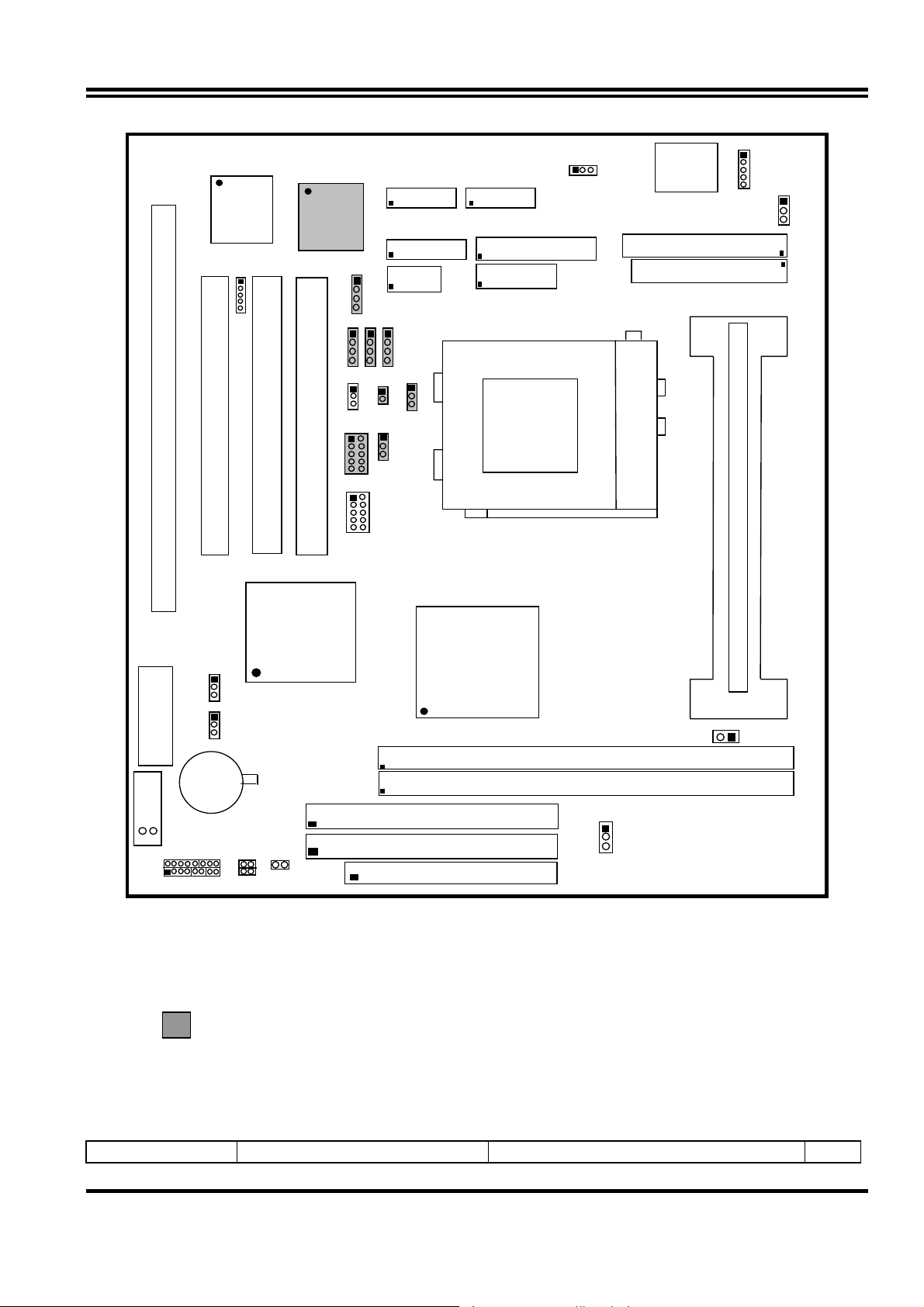
SYSFAN
CPUFAN
U13
BIOS
U3
IR
U2
SPKIN1
COM1COM2
GAME
VGA
MS PIN1
PW2
U5
ISA1
PCI1
PCI3
PCI2
JP6
JP7
CPU
PGA 370
SLO T-1
USB
SIS
5595
SIS
620
WOL
JP8
BATT
U14-7
SPEK RST TBLED
BT1
HDLED
DIMM1
DIMM2
FL OPPY
Figure 2-1
Optional connector for motherboard that embedded wit Audio Chip
2-3
Jumpers
Quick Reference for Jumpers, Connectors & Expansion Socket
Jumper Name Description Page
4
Page 7

U14-7 CPU Bus Frequency Selection Open:100MHZ(off), Closed:66MHz(on) p.6
JP8 CMOS RAM Clear 1-2 Clear CMOS, 2-3 Normal p.7
J5 On board VGA Enabled/Disabled open : Enabled,closed : Disabled p.7
JP1 Keyboard power on function 1-2 : Enabled , 2-3 : Disabled p.7
JP9 VIO Voltage Selection 1-2 : 3.45V , 2-3 : 3.52V p.7
Connectors
Connector Name Description Page
PW1 AT Power Connector 12-Pin Block p. 12
PW2 ATX Power Connector 20-Pin Block p. 12
ATKB Keyboard Connector 5-Pin Female p.12
MS_PIN1 PS/2 Mouse Connector 5-Pin Block p.12
LPT1 Parallel Port Connector 26-Pin Block p.13
COM1,COM2 Serial Port COMA & COMB 10-Pin Block p.13
FDD Floppy Driver Connector 34-Pin Block p.13
IDE1 Primary IDE Connector 40-Pin Block p.14
IDE2 Secondary IDE Connector 40-Pin Block p.14
HDLED IDE activity LED 2-Pin Connector p.14
FPC Front Panel Connector 16-Pin Block p.14
IR Infrared Module Connector 5-Pin Block p.15
USB USB Port Connector 10-Pin Block p.15
CPUFAN,SYSFAN FAN Connector Fanning system connectors p.15
PS-ON ATX power button/soft power button 2-Pin Connector p.15
VGA VGA Connector 16-Pin Block p.16
WOL Wake On Lan 3-pin Block p.16
Jumpers & Connectors (Option for motherboard that embedded Audio Chip)
Item number Name Description Page
JP6 Audio Chip Enabled/Disabled 1-2 Enabled, 2-3 Disabled p.7
Audio Line IN / Line OUT / MIC 10-pin Connector p.16
Game Game port Connector 16-pin Connector p.16
JP3 CD-Audio IN 4-pin Block p.17
JP4 CD-Audio IN 4-pin Block p.17
JP5 AUX IN 4-pin Block p.17
SPDIFIN SPDIN(Sony/Philips Digital Interface) IN 4-pin Block p.17
SPDIFOUT SPDIN(Sony/Philips Digital Interface) OUT 4-pin Block p.17
JP7 For Optional Optical Kit Connector 10-pin Block p.17
Expansion Sockets
Socket/Slot Name Description Page
Slot1 CPU Slot
Zip Socket 370 CPU Socket Celeron PPGA / FCPGA CPU Socket p.9
DIMM1,DIMM2 DIMM Module Socket 168-Pins DIMM SDRAM Module Expansion Socket p.9
PCI1, PCI2, PCI3 PCI Slot 32-bits PCI Local Bus Expansion slots p.11
ISA1 ISA Slot 16-bits ISA Bus Expansion slot p.11
PentiumII/III/Coppermine CPU Slot
p.8
2-4 Installation Steps
Before using your computer, you must follow the steps as follows:
1. Set Jumpers on the Motherboard
5
Page 8
2. Install the CPU
3. Install DRAM Modules
4. Install Expansion card
5. Connect Cables, Wires, and Power Supply
2-5 Jumper Settings
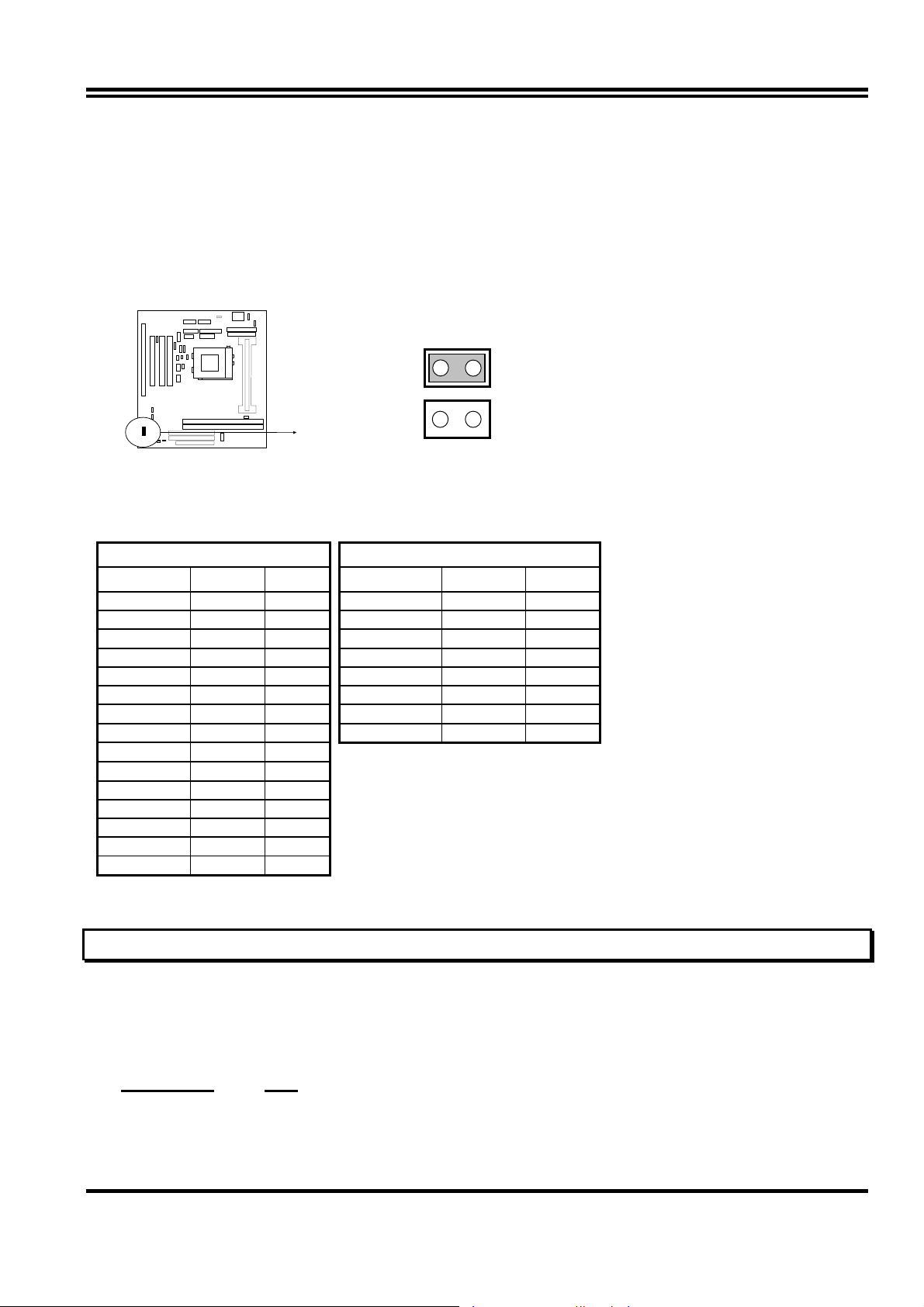
1. CPU Bus Frequency Selection : U14-7
U14-7
66MHz : Closed
100MHz : Open
※
You can also set the CPU Bus frequency and CPU ratio from the “CHIPSET FEATURES
SETUP” under BIOS SETUP.
Table for the Pentium III and Celeron Socket 370 CPU
Celeron Pentium III
Speed Bus Ratio Speed Bus Ratio
300/66 66MHz 4.5x 500E/100 100MHz 5.0x
333/66 66MHz 5.0x 550E/100 100MHz 5.5x
366/66 66MHz 5.5x 600E/100 100MHz 6.0x
400/66 66MHz 6.0x 650E/100 100MHz 6.5x
466/66 66MHz 7.0x 700/100 100MHz 7.0x
500/66 66MHz 7.5x 750/100 100MHz 7.5x
533/66 66MHz 8.0x 800/100 100MHz 8.0x
533A/66 66MHz 8.0x 850/100 100MHz 8.5x
566/66 66MHz 8.5x
600/66 66MHz 9.0x
633/66 66MHz 9.5x
667/66 66MHz 10.0x
700/66 66MHz 10.5x
733/66 66MHz 11.0x
766/66 66MHz 11.5x
∗ Because the Ratio are fixed by CPU Manufacture, users don’t need
to setting ratio any more, this table just for reference use.
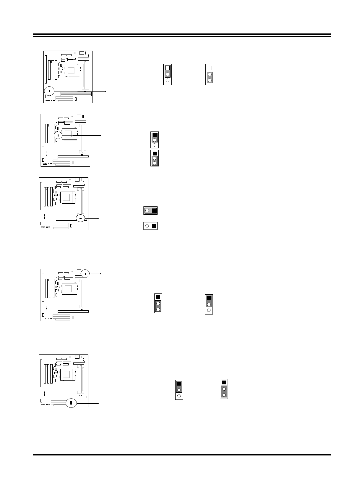
2. CMOS RAM Clear: JP8 (Yellow color selector)
WARNING: Make sure your computer is POWER OFF when you CLEAR CMOS.
Connect a jumper Cap over this jumper for a few seconds, will clears information stored in
the CMOS RAM Chip that input by user, such as hard disk information and passwords.
After CLEAR CMOS, you must enter the BIOS setup (by holding down <DEL> during
power-up) to re-enter BIOS information (see BIOS SETUP).
Selections JP8
Normal 2-3 (Default)
Clear CMOS 1-2 (momentarily)
6
Page 9
6
JP8
1
2
3
Normal
JP8
1
2
3
Clear CMOS
CMOS RAM (Normal / Clear CMOS Data)
3. On Board Audio Chip Enabled / Disabled connector: JP6
1
JP
Closed (Default) : Enabled
Open : Disabled
4. On board VGA function Enabled / Disabled connector: J5
J5
Closed : Disabled
1
Open (Default) : Enabled
5. Keyboard Power on function: JP1
This function only support when use ATX power supply . When choose 1-2 closed
and use ATX power supply , you can choice power on system by power button or
keyboard in “KB Power ON Password” item under “Power Management Setup”.
1
JP 1
2-3 closed : Disabled
1
JP1
1-2 closed : Enabled(Default)
6. VIO Voltage Setting Connector : JP9
The VIO Voltage Jumper Allow you to Select the Voltage Suppied to the DRAM , Chipset
and the CPU’S I/O buffer.
1
2-3 closed : 3.52V
1
1-2 closed : 3.45V (Default)
2-6 System Memory (DRAM)
7
Page 10
This main board supports two 168-pins DIMM modules, the Max Memory Size is 1.0GB
Because of the VGA share memory function, the system must always occupy BANK0
(DIMM1)to booting the system.
DIMM 1 DIMM 2 System can be
Accept or Not
168-pin DIMM
168-pin DIMM 168-pin DIMM
×
168-pin DIMM
×
× ×
∗
Because of share memory function, the system must always occupy DIMM1 first to boot
Accept
Accept
Not Accept
Not Accept
up the system .
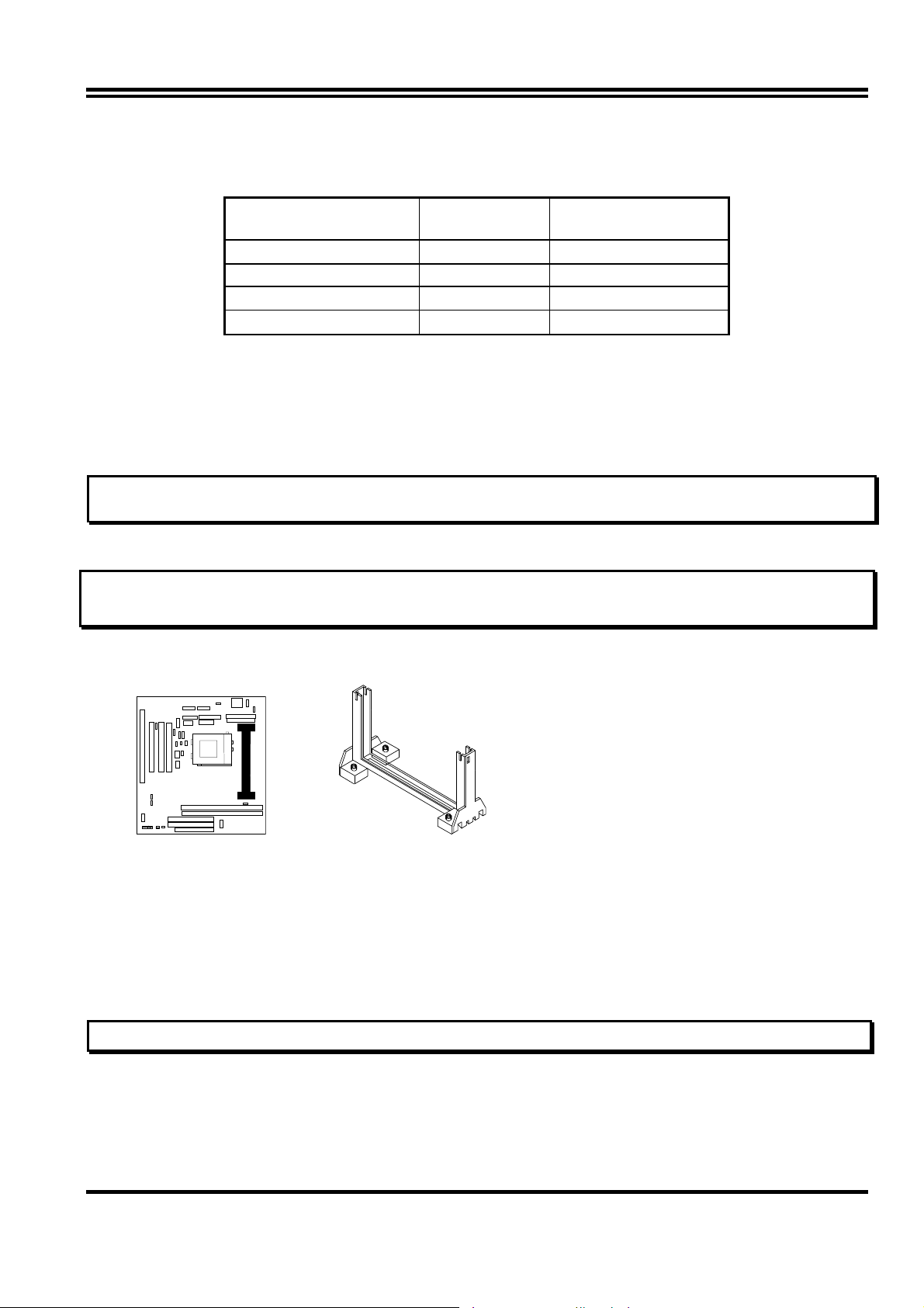
2-7 Central Processing Unit (CPU)
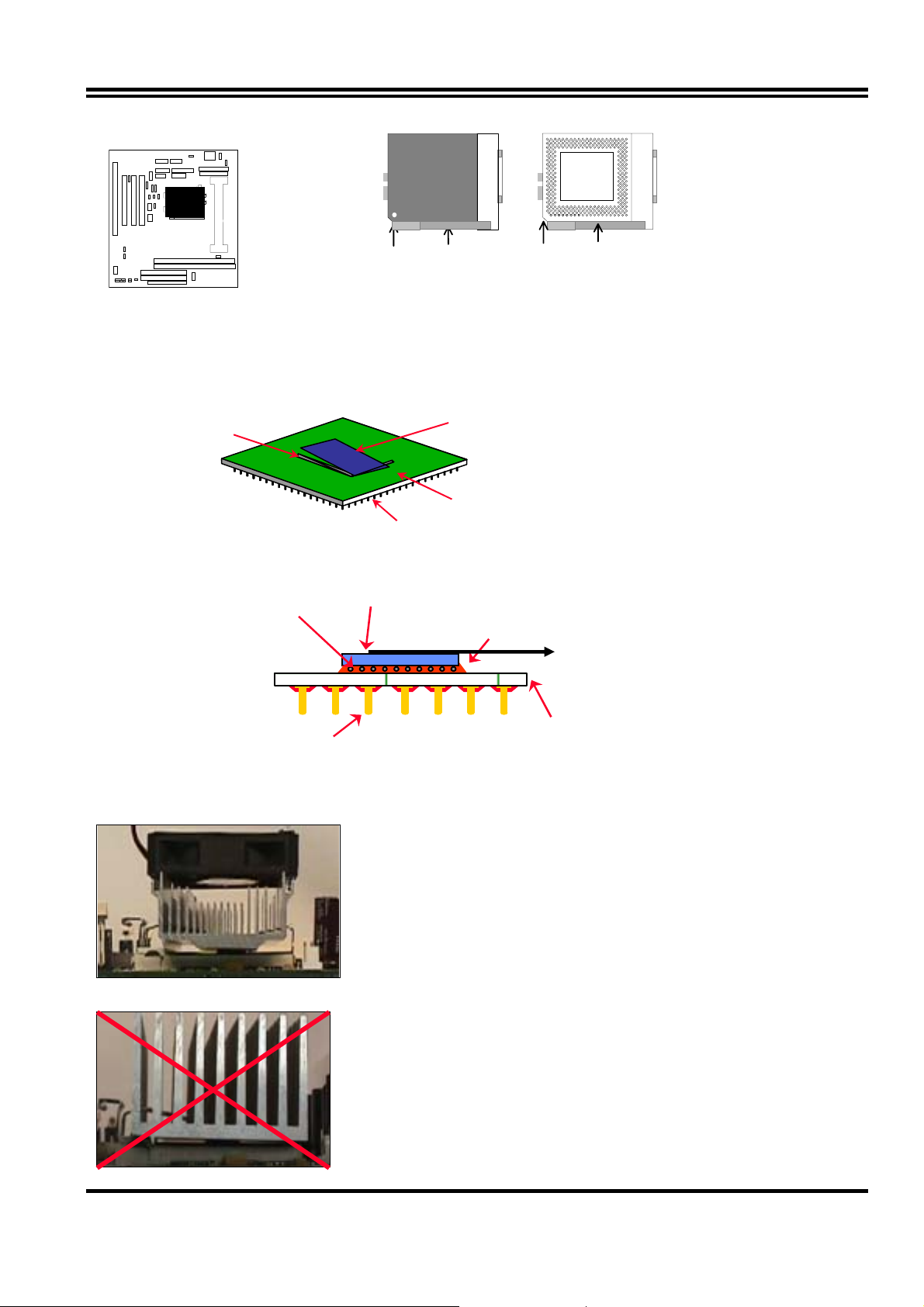
2-7-1 The motherboard provides a Slot-1 for Pentium II/III processor. The CPU on board
must have a fan or heat sink attached to prevent overheating.
WARNING: Without a fan or heat sink, the CPU will overheat and cause damage to both the CPU
and the motherboard.
To install a CPU, first turn off your system and remove its cover. Locate the Slot- 1 and place
RETENTION MODULE as fo llowing:
IMPORTANT: You must set jumper U14-7 for “Bus Frequency Selection” on page 6 depending on
the CPU that you install.
1. Attach heat sink to the CPU.
2. Place Part A on slot-1 and gently screw four corners on top of the mother- board.
PART A
2-7-2 The mainboard also provides a 370-pin ZIF Socket 370. The CPU on mainboard must
have a fan attached to prevent overheating.
To install a CPU, first turn off your system and remove its cover. Locate the ZIF Socket and
open it by first pulling the lever sideways away from the socket then upwards to a 90-degree
right angle. Insert the CPU with the white dot as your guide. The white dot should point
towards the end of the level. The CPU has a corner pin for three of the four corners, the CPU
will only fit in the one orientation as shown as follow. With the added weight of the CPU fan,
no force is required to insert the CPU. Once completely inserted, hold down on the fan and
close the Socket’s lever.
IMPORTANT: You can setting the CPU ratio and Host Frequency under “Chipset Features Setup”.
8
Page 11
White Dot
CPU
Socket 370
Lever
CPU ZIF Socket 370
Blank
Lock
Socket 370
2-7-3 Intel® Pentium® III Processor (256K) in the FC-PGA form factor: Mechanical Features
The FC-PGA package has the processor’s silicon die directly mounted to a pinned interposer substrate.
The pin grid array is partially populated and there may be surface mount components in the unpopulated
central area of the pin field.
Fillet Epoxy
Flip Chip Die
(Not to scale)
Pins
Substrate
Intel® Pentium® III Processor in the FC-PGA form factor: Mechanical Features
C4 Solder bumps
Flip-Chip Si Core
Fillet Epoxy
Surface mounted pins
Reference Design: Heatsink
FC-PGA with the reference
design heatsink
Multi-layer substrate
(Not to scale)
z Intel’s reference design thermal solution is an
active heatsink; an extruded aluminum heatsink
base and a fan attached to the top on the fin
array.
• Heatsinks for the PPGA will not work with the
FC-PGA. A pedestal is required on the
underside of the heatsink to clear the socket
z Recommended thermal interface
material: Chomerics* XTS454.
9
Page 12
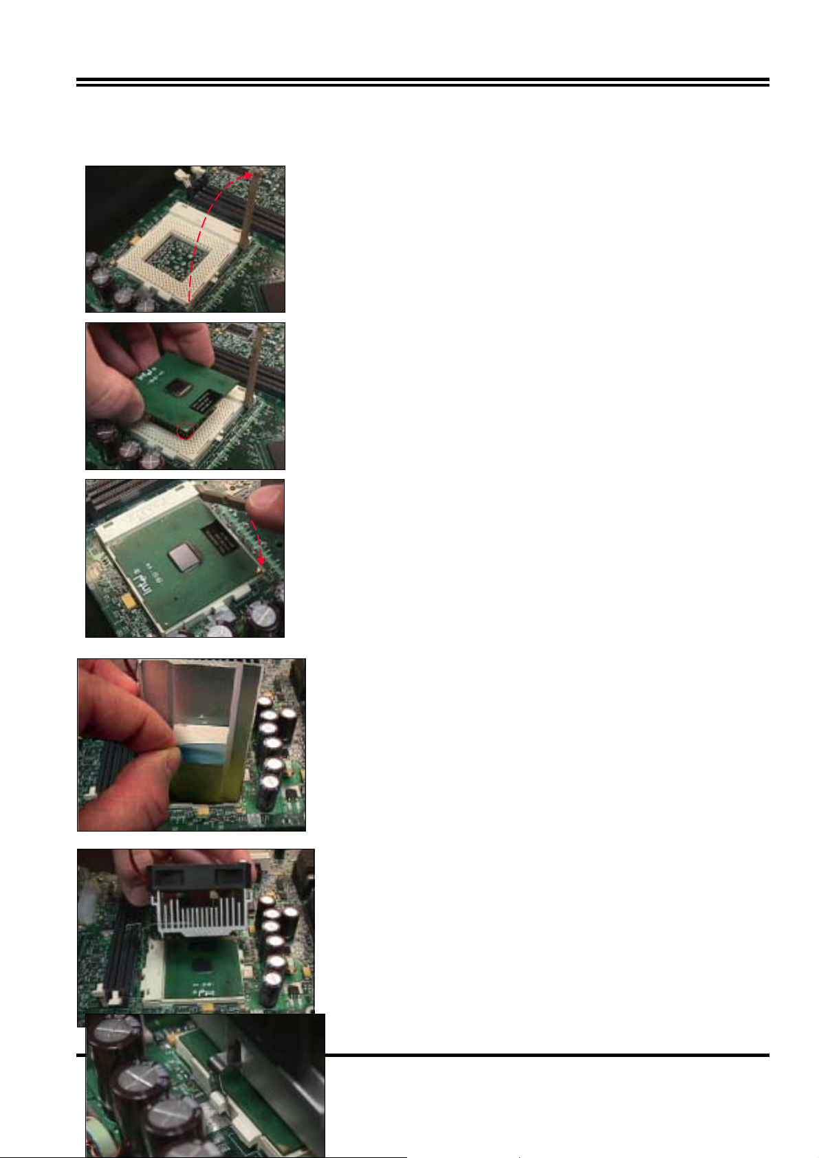
FC-PGA with a PPGA heatsink
CPU Insertion
Step 1
Open the socket by raising the actuation lever.
Step 2
Insert the processor.
Ensure proper pin 1 orientation by aligning the
FC-PGA corner marking with the socket corner
closest to the actuation arm tip. The pin field is
keyed to prevent mis-oriented insertion.
Don’t force processor into socket. If it does not go in
easily, check for mis-orientation and debris.
Make sure the processor is fully inserted into the
socket on all sides.
Step 3
Close the socket by lowering and locking the
actuation lever.
Heatsink Attachment
Step 1
Remove the protective liner from the thermal interface
material on the underside of the heatsink.
This liner is not normally present on the Intel reference
active heatsink.
Step 2
Orient the heatsink with the keyed edge of
heatsink along the cam box side of the
processor.
The clip should be oriented so that the thumb tab will
engage on the cam box side of the socket.
Step 3
Seat the heatsink onto the processor and engage
10
the clip opposite from the cam box onto its socket
tab first.
CAUTION: Do not slide the heatsink once it is
attached to the processor as the thermal interface
Page 13

2-8 Expansion Cards
You must read the documentation come with expansion card for any hardware or software
settings that may be required to setup your specific card.
Installation Procedure:
1. Read the documentation from your expansion card.
2. Set any necessary jumpers on your expansion card.
3. Remove your computer’s cover.
4. Remove the bracket on the slot you intend to use.
5. Carefully align the card’s connectors and press firmly.
6. Secure the card on the slot with the screw you remove in step 4.
7. Replace the computer’s cover.
8. Setup the BIOS if necessary.
9. Install the necessary software drivers for your expansion card.
Assigning IRQs for Expansion Cards
Some expansion cards may require an IRQ to operate. Generally an IRQ must be
exclusively assigned to only one device. In an standard design there are 16 IRQs available
but most of them are occupied by the system and leaves 6 free for expansion cards.
With moset recent device, the BIOS automatically assign an IRQ number to PCI expansion
cards. Please make sure there are no any of two devices use same IRQ, otherwise your
computer may experience some problem when those two devices are in use at the same time.
Assigning DMA Channels for ISA Cards
Some devices may also need a DMA (Direct Memory Access) channel. Its assignments for
this motherboard are handled same way as the IRQ assignment process described above.
The DMA channel is selectable in the PCI and PNP configuration section under BIOS Setup
utility.
2-9 External Connectors
11
Page 14
ORG
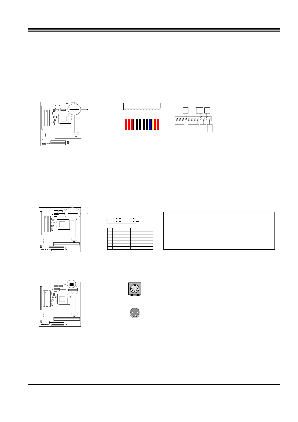
1. Power connector: AT Power Connector (12-pin block): PW1
This connector connects to a standard AT power supply. To connect the leads from the
power supply, ensure first that the power supply is not plugged. Most power supplies
provide two plugs (P8 and P9), each containing six wires, two of which are black. Orient
the connectors so that the black wires are located in the middle.
Using a slight angle, align the plastic guide pins on the lead to their receptacles on the
connector. Once aligned, press the lead onto the connector until the lead locks into place.
GND
+5V-12V-5V
PG+12V
P8P9
+5V
Power Connector on Motherboar d
Power Plugs from Power Suppl y
2. Power Connector: ATX Power Connector (20-pin block): PW2
ATX Power Supply connector. This is a new defined 20-pins connector that usually
comes with ATX case. The ATX Power Supply allows to use soft power on momentary
switch that connect from the front panel switch to 2-pins Power On jumper pole on the
motherboard. When the power switch on the back of the ATX power supply turned on,
the full power will not come into the system board until the front panel switch is
momentarily pressed. Press this switch again will turn off the power to the system board.
Pin 1
PIN ROW2 ROW1
1 3.3V 3.3V
2 -12V 3.3V
3 GND GND
4 Soft Power On 5V
5 GND GND
6 GND 5V
* Please don’t turn off / on power supply too
quickly. We recommend at least wait 4 sec
before turn on the power to protect the system.
3. Keyboard Connector (5-pin female): ATKB
This connection is for a standard IBM-compatible keyboard. May also be known as a 101
enhanced keyboard.
Keyboard Connector (5-pins female)
Connector Plug from Keyboard
4. PS/2 Mouse Connector (5-pin block): MS_PIN1
If you are using a PS/2 mouse, you must purchase an optional PS/2 mouse set which
connects to the 5-pins block and mounts to an open slot on your computer‘s case.
12
Page 15

ppy
D
PIN 1
PS/2 Mous e Module Connecto r
5. Parallel Printer Connector (26-pin Block): LPT1
Connection for the enclosed parallel port ribbon cable with mounting bracket. Connect the
ribbon cable to this connection and mount the bracket to the case on an open slot. It will
then be available for a parallel printer cable.
NOTE: Serial printers must be connected to the serial port. You can enable the parallel port and choose the
IRQ through BIOS Setup.
LPT
Pin 1
Parallel Printer Connector
6. Serial port COMA and COM B Connector ( Two 10-pin blocks): COM1, COM2
These connectors support the provided serial port ribbon cables with mounting bracket.
Connect the ribbon cables to these connectors and mount the bracket to the case on an
open slot. The two serial ports on the mounting bracket will then be used for pointing
devices or other serial devices. See BIOS configuration of “Onboard Serial Port”
COM 1
Pin 1
COM 2
Pin 1
Serial port COMA and COMB Connector
7. Floppy drive Connector (34-pin block): FDD
Thi s connector supports the provided floppy drive ribbon cable. Aft er conn ect ing the sin gle
plug end to motherboard, connect the two plugs at other end to the floppy drives.
FD
Pin 1
Flo
Drive Connector
8. Primary IDE Connector (40-pin block): IDE1
13
Page 16

This connector supports the provided IDE hard disk ribbon cable. After connecting the
single plug end to motherboard, connect the two plugs at other end to your hard disk(s). If
you install two hard disks, you must configure the second drive to Slave mode by setting
its jumpers accordingly. Please refer to the documentation of your hard disk for the jumper
settings.
Pin 1
Primary IDE Connector
9. Secondary IDE Connector (40-pin block): IDE2
This connector connects to the next set of Master and Slave hard disks. Follow the same
procedure described for the primary IDE connector. You may also configure two hard
disks to be both Masters using one ribbon cable on the primary IDE connector and
another ribbon cable on the secondary IDE connector.
Pin 1
Secondary IDE Connector
10. IDE activity LED: HDLED
This connector connects to the hard disk activity indicator light on the case.
HDLED
+-
IDE (Hard Drive) LED
11. Front Panel Connector: This 16-pin connector to connect to case front panel switch.
A. Turbo LED switch: TBLED
The motherboard‘s turbo function is always on. The turbo LED will remain constantly lit
while the system power is on. You may also to connect the Power LED from the
system case to this lead. See the figure below.
B. Reset switch lead: RST
This 2-pin connector connects to the case-mounted reset switch for rebooting your
computer without having to turn off your power switch. This is a preferred method of
rebooting in order to prolong the life of the system‘s power supply. See the figure
below.
C. Keyboard lock switch lead & Pow er LED: KEYLOCK & PW
This 5-pin connector connects to the case-mounted key switch for locking the
keyboard for security purposes and Power LED together.
14
Page 17

W
G
X
VCC
Vcc
C
D. Speaker connector: SPEAKER
This 4-pin connector connects to the case-mounted speaker. See the figure below.
Keyboard
Lock
GND
GND
NC
GND
GND
NC
ND
Speaker
Turbo LED
Reset S
System Case Connections
12. IR infrared module connector: IR
This connector supports the optional wireless transmitting and receiving infrared module.
This module mounts to small opening on system cases that support this feature you must
also configure the setting through BIOS setup. Use the five pins as shown on the Back
View and connect a ribbon cable from the module to the m oth erb oa rd acc ord ing to th e p in
definitions.
IR
N.C
IRR
GND
Infrared Module Connector
1
2
3
4
5
13. USB Port connector: USB
+ DATA
USB
-
DATA
GND
Pin 1
Vcc
NC
DATA
-
+DATA
GND
N
USB Port Connector
14. FAN connector: CPUFAN , SYSFAN
SYSFAN
1
Fan Connector
CPUFAN
1
15. ATX Power button/ Soft Power button: PS-ON
When using ATX power, the system power can be controlled by a momentary switch
connected to PS-ON Pushing the button once will switch the system between ON and
15
Page 18

VGA
ON
A
SLEEP. Pushing the switch while in the ON mode more than 4 seconds will turn the
system off. The system Power LED shows the status of the system’s power.
Selections PS-ON
One touch Power ON/OFF 2-4
24
PS-ON
ATX Power button/Soft Power button
16. VGA connector: VGA
This connector supports the provided VGA cable with mounting bracket. Connect the
ribbon cable to connector and mount the bracket to the case on an open slot .
Orient the red stripe on the
16
15
mo nitor cable with Pin 1
2
1
VGA Connector
17. Wake On Lan connector: WOL
WOL
+ 5VSB
GND
W
Jumpers & Connectors (Option for motherboard that embedded Audio Chip)
18. Audio connector: Audio
Orient the red stripe on the
monitor c able with Pi n 1
Audio
Game
GND
MICP
GND
L – I N - R
UDIO
2
1
GND
MIC
Audio Connector
L – I N - L
L – OUT - R
10
9
L – OUT - L
16
Page 19

7
19. Game Port connector: GAME
Orient the red stripe on the
monitor cable w ith Pin 1
Audio
GAME
2
16
1
GAME PORT Connector
15
20. CD-ROM Audio connector: JP3,JP4
JP4
1
2
3
4
JP3
1
2
3
4
CD-ROM Audio connector
21. PC Speaker signal Input connector: SPKIN 1
SPKIN 1
Game
22. SPDIF (Sony / Philips Digital Interface) Input / Output Connectors: SPDIFIN 1 /
SPDIFOUT
+5V
SPDIFOUT
GND
SPDIFOUT
SPDIFIN
GND
SPDIFIN 1
23. Optical kit connector: JP7
JP
1
17
Page 20

Chapter 3
AWARD BIOS SETUP
Award's ROM BIOS provides a built-in Setup program which allows user modify the basic
system configuration and hardware parameters. The modified data will be stored in a batterybacked CMOS RAM so data will be retained even when the power is turned off. In general,
the information saved in the CMOS RAM stay unchanged unless here is configuration change
in the system, such as hard drive replacement or new equipment is installed.
It is possible that CMOS had a battery failure which cause data lose in CMOS_RAM. If so,
re_enter system configuration parameters become necessary.
To enter Setup Program
Power on the computer and press <Del> key immediately will bring you into BIOS CMOS
SETUP UTILITY.
ROM PCI/ISA BIOS (2A6INJ19)
CMOS SETUP UTILITY
STANDARD CMOS SETUP
BIOS FEATURES SETUP
CHIPSET FEATURES SETUP
POWER MANAGEMENT SETUP
PNP/PCI CONFIGURATION
LOAD BIOS DEFAULTS
LOAD SETUP DEFAULTS
AWARD SOFTWARE, INC.
INTEGRATED PERIPHERALS
PASSWORD SETTING
IDE HDD AUTO DETECTION
SAVE & EXIT SETUP
EXIT WITHOUT SAVING
Esc : QUIT ↑↓→← : Select Item
F10 : Save & Exit Setup (Shift) F2 : Change Color
Figure 3-1
The menu displays all the major selection items and allow user to select any one of shown
item. The selection is made by moving cursor (press any direction key) to the item and press
<Enter> key. An on_line help message is displayed at the bottom of the screen as cursor is
moving to various items which provides user better understanding of each function. W hen a
selection is made, the menu of selected item will appear so the user can modify associated
configuration parameters.
3-1 STANDARD CMOS SETUP
Choose "STANDARD CMOS SETUP" in the CMOS SETUP UTILITY Menu (Figure 3-1). The
STANDARD CMOS SETUP allows user to configure system setting such as current date and
time, type of hard disk drive installed in the system, floppy drive type, and the type of display
monitor. Memory size is auto-detected by the BIOS and displayed for your reference. When
a field is highlighted (direction keys to move cursor and <Enter> key to select), the entries in
the field will be changed by pressing <PgDn> or <PgUp> keys or user can enter new data
directly from the keyboard.
18
Page 21

Modify
ROM PCI/ISA BIOS (2A6IMJ19)
STANDARD CMOS SETUP
AWARD SOFTWARE, INC.
Date (mm:dd:yy) : Tue, Feb, 23 1999
Time (hh:mm:ss) : 13 : 43 : 56
HARD DISKS TYPE SIZE CYLS HEAD PRECOMP LANDZ SECTOR MODE
Primary Master : Auto 0 0 0 0 0 0 Auto
Primary Slave : Auto 0 0 0 0 0 0 Auto
Secondary Master : Auto 0 0 0 0 0 0 Auto
Secondary Slave : Auto 0 0 0 0 0 0 Auto
Drive A : 1.44M , 3.5 in.
Drive B : None
Video : EGA/VGA
Halt On : All Errors
Esc : Quit ↑↓→← : Select Item Pu/Pd/+/- :
F1 : Help (Shift)F2: Change Color
Base Memory : 640K
Extended Memory : 7168K
Other Memory : 384K
Total Memory : 8192K
Figure 3-2
NOTE: If hard disk Prim ary Master/Slave and S econdary Master/Slave were used Aut o, than the
hard disk size and model will be auto-detect on display during POST.
NOTE: The "Halt On:" field is to determine when to halt the system by the BIOS is error occurred
during POST.
3-2 BIOS FEATURES SETUP
Select the "BIOS FEATURES SETUP" option in the CMOS SETUP UTILITY menu allows
user to change system related parameters in the displayed menu. This menu shows all of the
manufacturer's default values of this motherboard. Again, user can move the cursor by
pressing direction keys and <PgDn> of <PgUp> keys to modify the parameters. Pressing [F1]
key to display help message of the selected item.
This setup program also provide 2 convinent ways to load the default parameter data from
BIOS [F6] or CMOS [F7] area if shown data is corrupted. This provides the system a
capability to recover from any possible error.
ROM PCI/ISA BIOS (2A6INJ19)
BIOS FEATURES SETUP
AWARD SOFTWARE, INC.
19
Page 22

Boot Sequence
A,C,SCSI
Virus Warning : Disabled
CPU Internal Cache : Enabled
External Cache : Enabled
CPU L2 Cache ECC Checking : Enabled
Processor Number Feature : Enabled
Quick Power On Self Test : Enabled
Swap Floppy Drive : Disabled
Boot Up Floppy Seek : Enabled
Boot Up NumLock Status : On
Memory Pariy Check : Enabled
Typematic Rate Setting : Disabled
Typematic Rate (Chars/Sec) : 6
Typematic Delay (Msec) : 250
Security Option : Setup
PCI/VGA Palette Snoop : Disabled
OS Select For DRAM > 64MB : Non-OS2
HDD S.M.A.R.T capability : Disabled
Report No FDD For WIN 95 : Yes
:
Figure 3-3
Video BIOS Shadow : Enabled
C8000-CBFFF Shadow : Disabled
CC000-CFFFF Shadow : Disabled
D0000-D3FFF Shadow : Disabled
D4000-D7FFF Shadow : Disabled
D8000-DBFFF Shadow : Disabled
DC000-DFFFF Shadow : Disabled
Esc: Quit ↑↓→← : Select Item
F1 : Help Pu/Pd/+/-:Modify
F5 : Old Values (Shift)F2 : Color
F6 : Load BIOS Defaults
F7 : Load Setup Defaults
Note: The Security Option contains "setup" and "system". The "setup" indicates that the
password setting is for CMOS only while the "system" indicates the password setting is for
both CMOS and system boot up procedure.
• Virus Warning: T his category flashes on the screen. During and after the system boots
up, any attempt to write to the boot sector or partition table of the hard disk drive will halt
the system and the following error message will appear, in the mean time, you can run an
anti-virus program to locate the problem. Default value is Disabled
Enabled: Activates automatically when the system boots up causing a warning message
to appear when anything attempts to access the boot sector or hard disk
partition table.
Disabled: No warning message to appear when anything attempts to access the boot
sector or hard disk partition table.
• CPU Internal Cache / External Cache: These two categories speed up memory access.
However, it depends on CPU/chipset design. The default value is Enable. If your CPU
without Internal Cache then this item "CPU Internal Cache" will not be show.
Enabled: Enable cachehis category speeds up Power On Self Test.
(POST) after you power on the computer.
Disabled: Disable cache
• Quick Pow er On Self Test: If it is set to Enable, BIOS will shorten or skip some check
items during POST.
Enabled: Enable quick POST
Disabled: Normal POST
• Boot Sequence: This category determines which drive computer searches first for the
DOS (Disk Operating System). Default value is A,C,SCSI.
System will first search for floppy disk drive, then hard disk drive and then SCSI device.
The options are: C, A, SCSI; C, CDROM, A; CDROM, C, A; D, A, S CSI; E, A, SCSI; F, A,
SCSI; SCSI, A, C; SCSI, C, A; C only; LS/ZIP, C.
• Swap Floppy Drive: The swap floppy drive. Default value is Disabled.
20
Page 23

Enabled: Floppy A & B will be swapped under the DOS
Disabled: Floppy A & B will be not swap
• Boot Up Floppy Seek: During POST, BIOS will determine if the floppy disk drive
installed is 40 or 80 tracks. 360K type is 40 tracks while 760K, 1.2M and 1.44M are all 80
tracks. The default value is Enabled.
Enabled: BIOS searches for floppy disk drive to determine if it is 40 or 80 tracks.
Note that BIOS can not tell from 720K, 1.2M or 1.44M drive type as they are
all 80 tracks.
Disabled: BIOS will not search for the type of floppy disk drive by track number.
Note that there will not be any warning message if the drive installed is 360K.
• Boot Up NumLock Status: The def ault value is On.
On: Keypad is number keys.
Off: Keypad is arrow keys.
• Boot UP System Speed: It selects the default system speed-the speed that the system
will run at immediately after power up.
High: Set the speed to high.
Low: Set the speed to low.
NOTE: The board default value is LOW in the field. Boot the system to controller turbo or De-turbo
by Onboard (Turbo Switch).
• Typematic Rate Setting: This determines the typematic rate.
Enabled: Enable typematic rate and typematic delay programming.
Disabled: Disable typematic rate and typematic delay programming. The system BIOS
will use default value of this 2 items and the default is controlled by keyboard.
• Typematic Rate (Chars /Sec):
6 : 6 characters per second 8 : 8 characters per second
10 : 10 characters per second 12 : 12 characters per second
15 : 15 characters per second 20 : 20 characters per second
24 : 24 characters per second 30 : 30 characters per second
• Typematic Delay (Msec): When holding a key, the time between the first and second
character displayed.
250 : 250 msec
500 : 500 msec
750 : 750 msec
1000 : 1000 msec
• Security Option: This category allows you to limit access to the system and Setup, or
just to Setup. The default value is Setup.
System: The system will not boot and access to Setup will be denied if the correct
password is not entered at the prompt.
Setup: The system will boot, but access to Setup will be denied if the incorrect
password is entered at the prompt.
NOTE: To disable security, select PASSWORD SETTING at Main Menu and then you will be
asked to enter password. Do not type anything and just press <Enter>, it will disable
security. Once the security is disabled, the system will boot and you can enter Setup freely.
• Video BIOS Shadow : It determines whether video BIOS will be copied to RAM, however,
it is optional from chipset design. Video Shadow will increase the video speed.
21
Page 24

Concurrent function(MEM)
Disabled
Concurrent function(PCI)
Enabled
Enabled: Video shadow is enabled
Disabled: Video shadow is disabled
• C8000 - CBFFF Shadow:
CC000 - CFFFF Shadow:
D0000 - D3FFF Shadow:
D4000 - D7FFF Shadow:
D8000 - DBFFF Shadow:
DC000 - DFFFF Shadow:
These categories determine whether optional ROM will be copied to RAM by 16K byte or
32K byte per/unit and the size depends on chipset.
Enabled: Optional shadow is enabled.
Disabled: Optional shadow is disabled.
3-3 CHIPSET FEATURES SETUP
This section allows you to configure the system based on the specific features of the installed
chipset. This chipset manages bus speeds and access to system memory resources, such as
DRAM and the external cache. It also coordinates communications between the conventional
ISA bus and the PCI bus. It must be stated that these items should never need to be altered.
The default settings have been chosen because they provide the best operating conditions for
your system. The only time you might consider making any changes would be if you
discovered that data was being lost while using your system.
ROM PCI/ISA BIOS (2A6INJ19)
CHIPSET FEATURES SETUP
AWARD SOFTWARE ,INC
Auto Configuration : Disabled
RAS Pulse Width Refresh : 5T
RAS Precharge Time : 3T
RAS to CAS Delay : 3T
ISA Bus Clock Frequency : PCICLK/4
Starting Point of Paging : 1T
SDRAM CAS Latency ; 3T
SDRAM WR Retite Rate : X-1-1-1
CPU to PCI Burst Mem. WR : Disabled
System BIOS Cacheable : Enabled
Video RAM Cacheable : Enabled
Memory Hole at 15M-16M : Disabled
AGP Aperture Size : 64MB
CPU Pipeline Control : Enabled
:
:
Figure 3-4
PCI Delay Transation : Disabled
Auto Detedt DIMM/PCI Clk : Enabled
Spread Spectrum : Disabled
CPU Host/SDRAM Clock : Default
CPU Clock Ratio Jumpless : Disabled
Processor Core Frequency : x1.5
Esc: Quit ↑↓→←: Select Item
F1 : Help Pu/Pd/+/-:Modify
F5 : Old Values (Shift)F2 : Color
F6 : Load BIOS Defaults
F7 : Load Setup Defaults
• DRAM Settings: The first chipset settings deal with CPU access to dynamic random
access memory (DRAM). The default timings have been carefully chosen and should
only be altered if data is being lost. Such a scenario might well occur if your system had
mixed speed DRAM chips installed so that greater delays may be required to preserve the
integrity of the data held in the slower memory chips.
• SDRAM CAS Latencyn : When synchronous DRAM is installed, the number of
22
Page 25

clock cycles of CAS latency depends on the DRAM timing. Do not reset this field from
the default value specified by the system designer.
The choice: 2T, 3T.
• AGP Apertur e Size : Select the size of the Accelerated Graphics Port (AGP) aperture.
The aperture is a portion of the PCI memory address range dedicated for graphics
memory address space. Host cycles that hit the aperture range are forwarded to the AGP
without any translation. See www.agpforum.org for APG inf orma tion.
The choice: 4 MB, 8MB, 16 MB, 32 MB, 64 MB, 128 MB, 256MB.
• CPU Host/SDRAM Clock : Choose CPU Front side Bus clock (Host Clock)/SDRAM Clock
The choice: 66/66,75/75,83/83,95/95,100/100.
• CPU Clock Ration Jumpless : Enable/disable the CPU Clock ration control.
The choice: Enabled, Disabled.
• Processor Core Frequency : Select Ratio.
The choice: X2.0,X2.5,X3.0,X3.5,X4.0,X4.5,X5.0,X5.5,X6.0,X6.5,X7.0,X7.5,X8.0
3-4 POWER MANAGEM ENT SETUP
The Power Management Setup allows you to configure you system to most effectively save
energy while operating in a manner consistent with your own style of computer use.
ROM PCI/ISA BIOS (2A6INJ19)
POWER MANAGEMENT SETUP
AWARD SOFTWARE, INC.
ACPI function : Enabled
Power Management : User Define
PM Control by APM : Yes
Video Off Option : Susp Stby-> Off
Video Off Method : V/H SYNC+Blank
Switch Function : Break/Wake
Doze Speed (div by) : 2/8
Stdby Speed(div by) : 1/8
MODEM Use IRQ : 3
Hot Key Fumction As : Power OFF
** PM Monitor **
HDD Off After : Disable
Doze Mode : Disable
Standby Mode : Disable
Suspend Mode : Disable
Figure 3-5
** PM Events **
HDD Ports Activity : Enabled
COM Ports Activity : Enabled
LPT Ports Activity : Enabled
VGA Activity : Enabled
IRQ [3-7 , 9-15], NMI : Enabled
IRQ 8 Bredk Suspend : Disabled
Power Button Over Ride : Instant OFF
Ring Power Up Control : Disabled
KB Power ON Password : Enter
Power Up by Alarm : Disabled
Esc: Quit ↑↓→←: Select Item
F1 : Help Pu/Pd/+/-: Modify
F5 : Old Values (Shift)F2 : Color
F6 : Load BIOS Defaults
F7 : Load Setup Defaults
• ACPI function: Select Enabled if your system has an ACPI function.
The choice: Enabled, Disabled.
• Switch Function: You can choose whether or not to permit your system to enter complete
Suspend mode. Suspend mode offers greater power savings, with a correspondingly
longer awakening period..
The choice: Break/Wake, Disabled.
• Doze Speed (div by) : Sets the CPU's speed during Doze mode. The speed is reduced to
a fraction of the CPU's normal speed. The divisors range from 1 to 8
The choice: 1~8.
23
Page 26

• Stdby Speed (div by) : Select a divisor to reduce the CPU speed during Standby mode to a
fraction of the full CPU speed. The speed is reduced to a fraction of the CPU's normal
speed. The divisors range from 1 to 8-0.
The choice: 1~8
• Hot Key Function : Select Enabled your system has a hot key for pany Function.
The choice: Power off, Suspend, Disabled.
• PM Timers : The following four modes are Green PC power saving functions which are
only user configurable when User Defined Power Management has been selected. See
above for available selections.
• HDD Off After : By default, this item is Disabled, meaning that no matter the mode the
rest of the system, the hard drive will remain ready. Otherwise, you have a range of
choices from 1 to 15 minutes or Suspend. This means that you can elect to have your
hard disk drive be turned off after a selected number of minutes or when the rest of the
system goes into a Suspend mode.
• HDD Ports Activity : When set to On (default), any event occurring at a HDD (serial) port
will awaken a system which has been powered down.
• COM Ports Activity : When set to On (default), any event occurring at a hard or floppy
drive port will awaken a system which has been powered down.
• LPT Ports Activity : W hen set to On (default), any event occurring at a LPT (printer) port
will awaken a system which has been powered down.
• VGA Activity : When set to On (default), any event occurring at VGA will awaken a
system which has been powered down.
The following is a list of IRQ’s, Interrupt ReQuests, which can be exempted much as the
COM ports and LPT ports above can. When an I/O device wants to gain the attention of
the operating system, it signals this by causing an IRQ to occur. When the operating
system is ready to respond to the request, it interrupts itself and performs the service.
As above, the choices are On and Off.
When set On, activity will neither prevent the system from going into a power management
mode nor awaken it.
• IRQ [ 3-7, 9-15], NMI
• IRQ 8 Break Suspend : You can Enable or Disable monitoring of IRQ8 (the Real Time
Clock) so it does not awaken the system from Suspend mode.
• KB Power ON Password : When you set a password for keyboard, The password you
set the keyboard that returns the system to Full On state.
• Power Button Over Ride : You could press the power button for more than 4 seconds
forces the system to enter the Soft-Off state when the system has “hung.”
The choice: Soft-Off, Delay 4 Sec.
• Ring Power Up Control : When you select Enabled, a signal from ring returns the
system to Full On state.
• Power Up by Alarm : When you select Enabled, the following fields appear. They let you
set the alarm that returns the system to Full On state.
The choice: Enabled, Disabled.
3-5 PNP/PCI CONFIGURATION SETUP
This section describes configuring the PCI bus system. PCI, or Personal Computer
Interconnect, is a system which allows I/O devices to operate at speeds nearing the speed the
CPU itself uses when communicating with its own special components. This section covers
some very technical items and it is strongly recommended that only experienced users should
make any changes to the default settings.
24
Page 27

Resources Controlled By : Manual
Reset Configuration Data: Disabled
IRQ-3 assigned to : PCI/ISA PnP
IRQ-4 assigned to : PCI/ISA PnP
IRQ-5 assigned to : PCI/ISA PnP
IRQ-7 assigned to : PCI/ISA PnP
IRQ-9 assigned to : PCI/ISA PnP
IRQ-10 assigned to : PCI/ISA PnP
IRQ-11 assigned to : PCI/ISA PnP
IRQ-12 assigned to : PCI/ISA PnP
IRQ-14 assigned to : Legacy ISA
IRQ-15 assigned to : Legacy ISA
DMA-0 assigned to : PCI/ISA PnP
DMA-1 assigned to : PCI/ISA PnP
DMA-3 assigned to : PCI/ISA PnP
DMA-5 assigned to : PCI/ISA PnP
DMA-6 assigned to : PCI/ISA PnP
DMA-7 assigned to : PCI/ISA PnP
ROM PCI/ISA BIOS (2A6INJ19)
PNP/PCI CONFIGURATION SETUP
AWARD SOFTWARE, INC.
Esc: Quit ↑↓→←: Select Item
F1 : Help Pu/Pd/+/-:Modify
F5 : Old Values (Shift)F2 : Color
F6 : Load BIOS Defaults
F7 : Load Setup Defaults
Figure 3-6
• Resource controlled by :
The Award Plug and Play BIOS has the capacity to automatically configure all of the boot
and Plug and Play compatible devices. However, this capability means absolutely nothing
unless you are using a Plug and Play operating system such as Windows95.
The choice: Auto, Manual.
• Reset Configuration Data:
Normally, you leave this field Disabled. Select Enabled to reset Extended System
Configuration Data (ESCD) when you exit Setup if you have installed a new add-on and
the system reconfiguration has caused such a serious conflict that the operating system
can not boot.
The choice: Enabled, Disabled .
• IRQ3/4/5/7/9/10/11/12/14/15:
When resources are controlled manually, assign each system interrupt as one of the
following types, depending on the type of device using the interrupt:
Legacy ISA Devices compliant with the original PC AT bus specification, requiring a
specific interrupt ( such as IRQ4 for serial port 1). PCI/ISA PnP Devices compliant with
the Plug and Play standard, whether designed for PCI or ISA bus architecture.
The choice: Legacy ISA, PCI/ISA PnP.
• DMA0/1/3/5/6/7 assigned to:
When resources are controlled manually, assign each system DMA channel as one of the
following types, depending on the type of device using the interrupt:
Legacy ISA Devices compliant with the original PC AT bus specification, requiring a
specific interrupt ( such as IRQ4 for serial port 1). PCI/ISA PnP Devices compliant with
the Plug and Play standard, whether designed for PCI or ISA bus architecture.
The choice: Legacy ISA, PCI/ISA PnP.
3-6 LOAD BIOS DEFAULTS
The "LOAD BIOS DEFAULTS" function loads the system default data directly from ROM and
initialize associated hardware properly. This function will be necessary only when the system
CMOS data is corrupted.
25
Page 28

STANDARD CMOS SETUP
BIOS FEATURES SETUP
CHIPSET FEATURES SETUP
POWER MANAGEMENT
PNP/PCI CONFIGURA
LOAD BIOS DEFAULTS
LOAD SETUP DEFAULTS
Esc : QUIT ↑↓→← : Select Item
F10 : Save & Exit Setup (Shift) F2 : Change Color
ROM PCI/ISA BIOS (2A6INJ19)
CMOS SETUP UTILITY
AWARD SOFTWARE, INC.
INTEGRATED PERIPHERALS
SUPERVISOR PASSWORD
USER PASSWORD
Load BIOS Default (Y/N)? Y
Time, Date, Hard Disk Type...
ECTION
FORMAT
SAVE & EXIT SETUP
EXIT WITHOUT SAVING
Figure 3-7
3-7 LOAD SETUP DEFAULTS
The "LOAD SETUP DEFAULTS" function loads the system default data directly from ROM
and initialize associated hardware properly. This function will be necessary only when the
system CMOS data is corrupted.
ROM PCI/ISA BIOS (2A6INJ19)
CMOS SETUP UTILITY
AWARD SOFTWARE, INC.
STANDARD CMOS SETUP
BIOS FEATURES SETUP
CHIPSET FEATURES SETUP
POWER MANAGEMENT SETUP
PNP/PCI CONFIGURA
LOAD BIOS DEFAUL
LOAD SETUP DEFAULTS
Esc : QUIT ↑↓→← : Select Item
F10 : Save & Exit Setup (Shift) F2 : Change Color
Load SETUP Default (Y/N)? Y
Time, Date, Hard Disk Type...
INTEGRATED PERIPHERALS
SUPERVISOR PASSWORD
USER PASSWORD
IDE HDD AUTO DETECTION
ORMAT
UP
EXIT WITHOUT SAVING
Figure 3-8
3-8 INTEGRATED PERIPHERALS SETUP
ROM PCI/ISA BIOS (2A6INJ19)
INTEGRATED PERIPHERALS
AWARD SOFTWARE, INC.
26
Page 29

Internal PCI : Both
IDE Primary Master PIO : Auto
IDE Primary Slave PIO : Auto
IDE Secondary Master PIO : Auto
IDE Secondary Slave PIO : Auto
Primary Master UltraDMA : Auto
Primary Slave UtraDMA : Auto
Secondary Master UtraDMA : Auto
Secondary Slave UtraDMA : Auto
IDE Burst Mode : Enabled
IDE HDD Block Mode : Enabled
Onboard FDC Controller : Enabled
Onboard Serial Port 1 : 3F8/IRQ4
Onboard Serial Port 2 : 2F8/IRQ3
IR Address Select : Disabled
Onboard Parallel Port 1 : 378/IRQ7
Parallel Port Mode ; SPP
PS/2 mouse function : Enabled
USB Controller : Enabled
USB Keyboard Support : Disabled
Init Display Frist : AGP
VGA Shared Memory Size : 2MB
MDA Support : Disabled
Current CPU Temperature : 40°C
Current CPUFAN Speed : 4500
Current SYSFAN Speed : 0
VCC(V): 5V Vcc3 : 3.3V
Vcc25 : 2.51V Vcore : 2.01V
Esc: Quit ↑↓→←: Select Item
F1 : Help Pu/Pd/+/-:Modify
F5 : Old Values (Shift)F2 : Color
F6 : Load BIOS Defaults
F7 : Load Setup Defaults
Figure 3-9
• Internal PCI / IDE: This chipset contains an internal PCI IDE interface with support
for two IDE channels.
The choice: Primary, Secondary, Both.
• IDE Primary Master/Slave PIO : The four IDE PIO (Programmed Input / Output) fields let
you set a PIO mode (0-4) for each of the four IDE devices that the onboard IDE interface
supports. Modes 0 through 4 provide successively increased performance. In Auto mode,
the system automatically determines the best mode for each device.
The choice: Auto, Mode 0, Mode 1, Mode 2, Mode 3, and Mode 4.
• Primary Master/Slave UltraDMA: UDMA (Ultra DMA) is a DMA data transfer protocol that
utilizes ATA commands and the ATA bus to allow DMA commands to transfer data at a
maximum burst rate of 33 MB/s. When you select Auto in the four IDE UDMA fields (for
each of up to four IDE devices that the internal PCI IDE interface supports), the system
automatically determines the optimal data transfer rate for each IDE device.
The choice: Auto, Disabled.
• IDE Burst Mode : Selecting Enabled reduces latency between each drive read/write cycle,
but may cause instability in IDE subsystems that cannot support such fast performance.
If you are getting disk drive errors, try setting this value to Disabled. This field does not
appear when the Internal PCI/IDE field, above, is Disabled.
The choice: Enabled, Disabled.
• Onboard FDD Controller: This should be enabled if your system has a floppy disk drive
(FDD) installed on the system board and you wish to use it. Even when so equipped, if
you add a higher performance controller, you will need to disable this feature.
The choice: Enabled, Disabled.
• Onboard Serial Port 1/Port 2 : This item allows you to determine access onboard serial
port 1/port 2 controller with which I/O address.
The choice: 3F8/IRQ4, 2E8/IRQ3, 3E8/IRQ4, 2F8/IRQ3, Disabled, Auto.
• IR Address Select : Select IR Address.
Choices are: Disabled, 2F8H, 3E8H, 2E8H.
• IR Mode : Select IR Mode.
Choices are: HP SIR, ASKIR.
• IR IRQ Select : Select IRQ for IR.
Choices are: IRQ3, IRQ4, IRQ10, IRQ11.
• Onboard Parallel Port 1 : This item allows you to determine access onboard parallel port
controller with which I/O address.
The choice: 3BC/IRQ7, 378/IRQ7, 278/IRQ5, Disabled.
27
Page 30

• Parallel Port Mode : Select an operating mode for the onboard parallel (printer) port.
Select Normal, Compatible, or SPP unless you are certain your hardware and software
both support one of the other available modes.
The choice: SPP, EPP, ECP, ECP+EPP.
• ECP Mode Use DMA : Select a DMA channel for the parallel port for use during ECP
mode.
The choice: 3, 1.
• PS/2 mouse function : If your system has a PS/2 mouse port and you install a serial
pointing device, select Disabled.
The choice: Enabled, Disabled.
• USB Controller : Select Enabled if your system contains a Universal Serial Bus (USB)
controller and you have USB peripherals.
The choice: Enabled, Disabled.
• Init Display First : This item allows you active which bus first (PCI Slot or AGP first).
The choice: PCI Slot, AGP. Default value is AGP.
• MDA Support : Enable this function allows system to support Monochrome adapter.
Default value is Disabled.
The choice: Enabled, Disabled.
• Current CPUFAN/SYSFAN Speed : These fields display the current speed of up to two
CPU fans, if your computer contains a monitoring system.
• Vcc/Vcc3/Vcc25/Vcore : These fields display the current voltage of up to four voltage
input lines, if your computer contains a monitoring system.
3-9 PASSWORD SETTING
This item lets you configure the system so that a password is required each time the system
boots or an attempt is made to enter the Setup program (Refer to Figure 3-3 for the details).
Supervisor Password allows you to change all CMOS settings but the User Password setting
doesn’t have this function. The way to set up the passwords for both Supervisor and User
are as follow:
1. Choose either Supervisor Password or User Password in the Main Menu and press
<Enter>. The following message appears:
“Enter Password:”
2. The first time you run this option, enter your password up to only 8 characters and press
<Enter>. The screen does not display the entered characters. For no password just
press <Enter>.
3. After you enter the password, the following message appears prompting you to confirm
the password:
“Confirm Password:”
4. Enter exact the same password you just typed again to confirm the password and press
<Enter>.
5. Move the cursor to Save & Exit Setup to save the password.
6. If you need to delete the password you entered before, choose the Supervisor Password
and Press <Enter>. It will delete the password that you bad before.
7. Move the cursor to Save & Exit Setup to save the option you did, otherwise the old
password will still be there when you turn on your machine next time.
3-10 IDE HDD AUTO DETECTIO N
The "IDE HDD AUTO DETECTION" utility is a very useful tool especially when you do not
know which kind of hard disk type you are using. You can use this utility to detect th e correct
disk type and install in the system automatically. Also you can set HARD DISK TYPE to
“Auto” in the STANDARD CMOS SETUP to have same result. T he BIOS will Auto-detect the
hard disk size and model on display during POST.
ROM PCI/ISA BIOS (2A6INJ19)
STANDARD CMOS SETUP
AWARD SOFTWARE, INC.
28
Page 31

Date (mm:dd:yy) : Thu, Mar, 12 1998
Time (hh:mm:ss) : 13 : 43 : 56
HARD DISKS TYPE SIZE CYLS HEAD PRECOMP LANDZ SECTOR MODE
Primary Master :
Primary Slave :
Secondary Master :
Sec
Esc : Quit ↑↓→← : Select Item Pu/Pd/+/- : Modify
F1 : Help (Shift)F2: Change Color
OPTIONS SIZE CYLS HEAD PRECOMP LANDZ SECTOR MODE
1 (Y) 0 0 0 0 0 0 NORMAL
Select Secondary Slave Option (N=Skip):N
Figure 3-10
NOTE: HDD Modes
The Award BIOS supports 3 HDD modes : NORMAL, LBA & LARGE
3-11 SAVE & EXIT SETUP
The "SAVE & EXIT SETUP" option will bring you back to boot up procedure with all the
changes you just made which are recorded in the CMOS RAM.
3-12 EXIT WITHOUT SAVING
The "EXIT WITHOUT SAVING" option will bring you back to normal boot up procedure
without saving any data into CMOS RAM. All of the old data in the CMOS will not be
destroyed.
Chapter 4
4-1 PC HEALTH MONITOR Driver Quick Installation
§
In Windows 95/ Windows 98
29
Page 32

step1: Run “X:\SiS620\HEALTH\SETUP.EXE” file .
step2: Selet “Next” to complete install driver.
step3: The program will automatic install driver to system if users have
question in system Hardware Monitor Setting, please read “HELP”
Section in program.
4-2 Sound Driver & Audio Rack Installation( Option for
Motherboard That Embedded Audio Chip ) :
Special Features for CMI8738 audio chip
PCI Plug and Play (PnP) bus interface, 32 bit PCI bus master.
Full duplex playback and recording, built-in 16 bits CODEC.
HRTF 3D positional audio, supports both Direct Sound 3D® & A3D® interfaces, supports
earphones, two and four channel speakers mode.
Support Windows 3.1 / 95 / 98 and Windows NT 4.0.
Built-in 32 OHM Earphone buffer and 3D surround.
MPU-401 Game/Midi port and legacy audio SB16 support.
Downloadable Wave Table Synthesizer, supports Direct Music®.
• Digital Audio (SPDIF IN/OUT)
Up to 24 bit stereo 44KHz sampling rate voice playback/recording.
Full duplex playback and recording, 120dB audio quality measured.
Auto detectable SPDIF/IN signal level from 0.5V to 5V.
• Stereo Mixer and FM Music Synthesizer
Stereo analog mixing from CD-Audio, Line-in
Stereo digital mixing from Voice, FM/Wave-table, Digital CD-Audio
Mono mixing from MIC and software adjustable volume
OPL3 FM synthesizer (4 operators)
Up to 15 melody sounds and 5 rhythm sounds (20 voices)
• Game and Midi Interface
Fully compatible with MPU-401 Midi UART and Sound Blaster Midi
mode/ Standard IBM PC joystick/game port (dual channels)
DOS Installation
Before beginning the installation, please make sure that your hard disk has sufficient
space(min. 4MB). Insert the Driver CD into the CD-ROM Drive.
1. Change directory to PCI audio DOS drivers folder (ex. X:\CMI8738\DOSDRV) at DOS
prompt, and type:
INSTALL [Enter]
2. Type DOS utilities path which you want to install.
3. Program will expand the file to the path which you've specified.
4. Install program will add initial drivers into AUTOEXEC.BAT file.
Win95/98 Installation
We recommend that you install Microsoft Windows before you install this PCI sound card,
and you not install any other sound card device drivers in your current system.
1. Turn on the computer , and enter the Microsoft Windows 95/98
2. Before install sound card driver please double-click “My Computer” icon, “Control Panel”
icon , “System” icon, and choose “Device Manager” item.
3. Check “Other Device” item ,if there have “PCI Multimedia Audio Device”, please remove
it first ,and Restart System again.
4. You w ill see a w indow s prompt like this:
“New Hardware Found PCI Multimedia Audio Device Windows has found new hardware
and is installing the software for it” , then the dialog box shown Click “Next” button to go on.
5. Click “Other Locations” button to specify drivers path:
“ X:\CMI8738\Win9X\DRV”
6. Select “OK” to finish install.
7. Now, system is installing device drivers automatically. After a while, the system will finish the
30
Page 33

installation includes the following dev ic e driv ers.
CMI8738/C3DX PCI Audio Device
CMI8738/C3DX PCI Audio Joystick Device
CMI8738/C3DX PCI Audio Legacy Device
DOS mode MPU-401 Emulator
8. Install Application Software : Click “start” key
9. Select “Run”
10. Key in the drive and path for Windows application installation program, for example,
in Win95 “X:\CMI8738\Win9X\APP\Win95\SETUP.EXE”
in Win98 “X:\CMI8738\Win9X\APP\Win98\SETUP.EXE”
11. Click “OK” to start the installation procedure, and follow the on-screen instructions to finish
the installation. When all the application softwares have been installed, please shut down
Windows 95/98 system, and reboot your system.
Win95/98 Un-Installation
If you install Win95/98 and a sound card at the same time, you might experience some
technical difficulties(the device might not function properly). It is suggested that you
proceed with the un-install procedure:
1. Click "start" button.
2. Select "run" item.
3. Find UINSTDRV.EXE in driver disk under Win95/98 drivers folder.
4. Run it.
5. Follow the on-screen instructions to re-install the hardware.
If you want to completely remove the drivers, you can also run the un-install procedure as
described previously. Remove the sound card from the slot, and then reboot the system.
Windows NT 4.0 Installation
We recommend that you install Windows NT 4.0 before you install this PCI audio card, and
you not install any other sound card device drivers in your current system.
1. Click “Start” button, move the highlight bar to “Setting” item, and select the “Control
Panel”.
2. Double-click “Multimedia” icon.
3. Select “Devices” page, and press “Add” button.
4. Select “Unlisted or Updated Driver” item in “List of Drivers”.
5. Specify the drive and the path where NT drivers are in (such as X:\CMI8738\NT40\DRV).
6. Select “C-Media CM8738” item and press “OK” button.
7. Select proper I/O value.
8. Press “OK” button.
9. Restart the system when being asked.
10. Now, you have already installed the PCI Audio Adapter under Microsoft W indows NT 4.0
successfully. if you want to install the Windows applications, continue the following steps:
11. Click “start” key.
12. Select “Run” item.
13. Key in drive and path for Windows NT application installation program, for example,
“X:\CMI8738\NT40\APP\SETUP.EXE”
14. Click “OK” to start the installation procedure, and follow the on-screen instructions to finish
the installation. When all of application softwares have been installed, shut down the
Windows NT system, and then reboot your system.
Windows Appc. (The Audio Rack)
Introduction
By means of a user-friendly interface(as easy as operating your home stereo system), this
PCI audio rack provides you with the control over your PC’s audio functions, including the
advantage of four speakers mode enable/ disable, and perfect digital sound ( SPDIF ) input /
output control.
31
Page 34

This Audio Rack consists of several major components:
Control Center: Controls the display of the PCI Audio Rack’s components.
MIDI Player: Plays MIDI music files, and allows you to create your personal song playlists,
and play the song files.
Wave Player: Records and plays digital audio (wave) files. Allows you to create wave file
playlists, and playback the wave files.
CD Player: Plays standard audio CDs. Allows you to create your favorite song playlists.
System Mixer: Controls the volume level of your audio inputs and outputs.
Showing or Hiding Audio Rack Components
To remove or add a component from the display, click on the component's button on the
Control Center’s Button Bar or toggle it off.
MIDI Player, Wave Player, and CD Player
CD Player (above, similar to Wave Player and MIDI Player)
Sel (or Trk) field: If you have multiple selections in your playlist, this shows the number of
the current selection or CD track.
Current File or Track: The name of the current MIDI file, wave audio file, or CD track.
Total Length field: displays the total length of files or tracks in minutes and seconds.
Current Time field: displays the current time of files or tracks in minutes and seconds when
playback or recording.
Please refer to the help screen for more detail button function descriptions. (click on help “ ”
button on the player)
System Mixer
System Mixer allows you to control all the audio output and input levels.
System Mixer displays the volume controls which your audio drivers make available. The
names for these controls may vary.
32
Page 35

Mixer panel while the four speakers mode is enabled.
Mixer panel while the four speakers mode is disabled.
Volume Control: Clicking on this button shows and allows you to use the output level controls.
Recording Control: Clicking on this button shows and allows you use the input level controls.
Input and Output Level Sliders and Buttons: For each input or output signal type, the
control slider controls the loudness whereas the horizontal slider controls the balance
between the two speakers. The mute button temporarily stops input or output without
changing slider positions.
Control types and names might vary. The common types are listed below:
• Vol: The master control for all outputs. The strength of an output signal is determined by
both the Vol slider and the slider for the individual output. To affect all outputs, move the
Vol slider. To change the output of an individual output type, move its slider.
• Line-in/Rear: Controls the audio hardware's Line In or Line Out levels. Line levels might
be for an externally attached cassette player, for instance, while the four speakers mode is
enabled, this control becomes the Rear speaker volume control.
• Mic: Controls the microphone input level.
• Wave: Controls wave (voice) playback or the recording levels.
• FM: Controls the FM music playback or the recording level.
• Aux-in: Controls the Aux-in music play or the recording level.
• PC-SPK: Controls the external PC speaker input level.
• CD: Controls the CD drive output level, for CD drives configured to play their audio output
through the PC’s audio hardware.
• 4SPK: Turn on or turn off the Rear speakers effect.
• Surround: Turn on or turn off the 3D surround sound effect.
• SPDIF-in: Turn on or turn off the SPDIF digital signal input.
• Advanced: Check the SPDIF status, HRTF 3D sound CPU Utilization, turn on th
Microphone Booster.
Mute Buttons: Toggle between muting and enabling the signal. A button with a lit LED is
enabled, and when it is not lit, it means it is mute. Several output signals can usually be
enabled at once.
MP3 Player : MP3 player can play both wave files and MP3 files.
33
Page 36

MP3 player while the loop function enables.
The settings’ window while one of the SPDIF functions is enable.
The 4 Speakers System
This Audio Adapter provides 2 wave channels(front/rear), known as the 4 speakers system.
When games or application programs via DirectSound® 3D or A3D® interface locate the
sound sources to the listener's back, the two rear speakers will work to enhance the rear
audio positional effect, so as to complement the insufficiency of using only two front speakers
to emulate the audio effect. The following is the hardware installation and the software setups:
1. The speaker installation.
Connect the front pair speakers to the Line-out jack of the audio adapter, and then connect
rear pair speakers to Line-in/Rear jack of the audio adapter. The original Line-in can be
moved to Aux-in.
2. The positions of the speakers
Put your speakers the way the following picture suggests, so as to avail yourself to the best
audio result.
3. The mixer setup
There is a 4 speakers option in the volume control of the mixer, and when you enable this
option, it means the rear speakers are connected to Line-in/Rear jack. When Line-in/Rear
jack is connected to other external Line-in sources, please DO NOT enable this option in
order to avoid hardware conflicts. Regarding rear speaker option, you can turn on or turn off
the output of the back speakers, and adjust the volume, to have the rear/front speakers have
the same volume.
4.The demo
Execute the "Helicopter" demo within the C3D HRTF Positional Audio Demos of this audio
adapter. When the helicopter flies behind you, the rear speakers will work.
Optical Kid for SPDIF/OUT (Option for motherboard that embedded PC Health chip)
The Optical Kid includes:
34
Page 37

z Optical Module
z Optical Cable
z Software DVD driver
DIP-SWITCH
OPTICAL OUT
J1:SPDIF-IN
OPTICAL IN
An example of optical kit with MD connection.
The application program setup(please install CMI8738 application program first)
When the connection is done, please go to the Start menu and select PCI Audio
Applications\Audio Environment Setting
35
Page 38

When all the procedures have been completed, there will be an infrared signal coming from
the SPDIF/OUT of the optical fiber of the sound card.
Please note that signal beam may cause severe damage to the eyes. For your safety,
please point the output end to a piece of white paper to check if thebeam is in function.
Please connect the output signal to the MD input, then play the music via the MP3 player.
36
Page 39

Please note that in playback, if there is no gap longer than three seconds betw een each track,
the MD can not recognize the tracks and will record all of them into one. It is recommended
that you set the gap time to 3~5 seconds to meet all type of MD requirements.
About Recording 24bit Audio Setting
37
Page 40

24-bit audio can only be applied to SPDIF IN/OUT mode; it does not apply to other
modes such as the four channels or the analog. No sound will be heard while in
playback, yet it can be recorded.
The un-selected area will be gray out.
38
Page 41

The un-selected area will be gray out.
The un-selected area will be gray out.
39
Page 42

You can double-click this circuit icon to have the following setting box. By means of this
setting box, you can also complete the above-mentioned setting procedures.
SPDIF/IN for motherboard that embedded Audio chip
An example of Portable CD Player(Output) t o Main Board (O ptical Input)Setup
40
Page 43

When the connection is done, please go to the Start menu and select PCI Audio
Applications\Audio Environment Setting
Loopback(bypass)mode setup
41
Page 44

CD ROM(Digital Output) to SPDIF/IN Setup
When the connection is done, please go to the Start menu and select PCI Audio
Applications\Audio Environment Setting
Please follow these setting procedures.
42
Page 45

Now you can insert the CD into the CD ROM drive, then activate C-MEDIA CD player and
push the ”play” button to do the recording job.
Please note that you have to set the MD in the simultaneous-recording mode.
43
 Loading...