

Page 1

603TCF/603TCFL
使 用 手 冊
Socket 370
奔騰處理器主機板
編號:
發佈日期 2002 年 8 月
商標:
*
包含在此文件之規格及資料僅為使用資訊的提供,任何修改將不另行通知,並且不應
視為廠商的承諾。
G03-603TCR1C
Page 2

使用者需知
手冊版本資訊
散熱解決方案
第㆒章
1-1
1-2
1-3
1-4
第㆓章 硬體安裝
2-1
2-2
2-3
2-3-1
2-3-2 CPU
2-3-3
2-3-4
2-4
2-5
2-5-1
2-5-2
2-5-3
2-6
2-6-1
2-6-2
2-7
........................................................................................ ii
..................................................................................... 1
..................................................................................... 1
603TCF/603TCFL
主機板特性
規格
性能表
..................................................................................... 3
設計圖及跳線設定
............................................................................ 2
.................................................................................. 4
硬體安裝步驟
檢查主機板的跳線設定
安裝
CPU
有關
CPU
超頻
安裝記憶體
擴充卡
.................................................................................. 12
擴充卡安裝過程
設定擴充卡的
主機板的㆗斷列表
連接埠,接頭
連接埠
接頭
啟動你的電腦
......................................................................... 7
................................................................................ 9
PENTIUM & CELERON™ 370 CPU
的設定
外頻
安裝
....................................................................... 10
....................................................................................
............................................................................ 11
IRQ
......................................................................... 13
.................................................................................
....................................................................................
......................................................................... 19
目 錄
主機板簡介
................................................................... 5
............................................................. 7
............................................................ 9
.....................................................................
..................................................................
..................................................................
的認識
............... 9
10
12
12
13
13
16
第㆔章
3-1
3-2
3-3
BIOS
進入
線㆖說明
主目錄
3-4 CMOS
3-5 BIOS
晶片組參數的進階設定
3-6
3-6-1 DRAM
周邊配備設定
3-7
3-7-1
3-7-2
3-7-3
介紹
SETUP
特性的進階設定
............................................................................ 20
............................................................................... 21
.................................................................................. 21
的標準設定
.................................................................. 23
.............................................................. 23
.............................................................. 24
的進階控制
.......................................................... 25
......................................................................... 26
內建之
內建裝置之功能設定
內建超級
裝置的功能設定
IDE
之功能設定
IO
.....................................................27
................................................................27
...........................................................28
i
Page 3

3-8
3-9 PNP/PCI
3-10
3-11
3-12
3-13
電源管理的設定
3-8-1
3-8-2
3-8-2.1 IRQ
省電管理
省電管理之喚醒事件的設定
組態設定
...................................................................... 28
.............................................................................................. 29
的工作範圍
...................................................................
................................................................. 30
系統環境狀態監控之設定
其它控制設定
........................................................................ 32
載入原廠預設值/最佳化之設定
設定監督者/使用者密碼
.......................................................29
30
......................................................... 31
.................................................. 32
........................................................... 33
第㆕章 驅動程式及附贈軟體的安裝
支援
WINDOWS 95/98/98SE/NT4.0/2000/XP
4-1 IDE
4-2 VGA
安裝
安裝
4-3 SOUND
4-4 LAN .......................................................................
裝
RTL8100
快速㆚太網路驅動程式
4-5 PC-HEALTH
4-5-1
如何使用
4-6 MAGIC BIOS
4-7 PC-CILLIN
如何關閉內建式音效卡
4-8
怎樣更新
4-9
BIOS
㆕合㆒驅動程式
VIA
VIA 8601 VGA
安裝
ALC
驅動程式
音效驅動程式
....................................................... 39
安裝
VIA
安裝
安裝
的硬體監控程式
VIA
硬體監控程式
BIOS
PC-CILLN2002
線㆖升級公用程式
............................................................. 45
........................................................................ 45
的
MAGIC INSTALL
.................................................. 35
............................................... 37
......................................... 38
...................................... 40
...................................................41
.................................. 41
防病毒程式
............................. 43
.................. 34
安
使用者需知
本手冊的版權屬於其製造廠商。其㆗的任何部分(包括所描述之產品和軟體)都不允
許在未經其製造廠商書面授權的情況㆘以任何形式或者採取任何方法複製、傳播或翻
譯成任何語言。
本手冊包含了使用本主機板所必須的所有資訊,並且我們確保本手冊能完全滿足使用
者的需求,如有任何改變或修正將不另行通知。廠商提供本手冊是不帶任何方式的擔
保,而且將不對㆒切直接的、間接的、特殊的、偶然的或是因此而產生的損害(包括
利潤損失,商業損失,使用數據時的損失,商業㆗斷等等)負責。
本手冊所使用的產品名稱及公司名稱可能不是其註冊商標或其註冊版權。僅用於說明
或解釋之作用,並無意侵犯其所有者的權益。
ii
Page 4

手冊版本資訊
版本 版本記錄 日期
1.0
項目表
603TCF/603TCFL
IDE/Floppy
主機板應用程式光碟片
603TCF/603TCFL
第㆒版 2002 年 8 月
排線
主機板
使用手冊
Intel ㆗央處理器的散熱解決方案 – 風扇
由於科技的日新月異,㆗央處理器 (CPU) 亦持續往更快速、更高的效能發展。因此在
建置電腦系統時,散熱的處理變得越來越重要了,㆒個適當的散熱環境,是讓系統更
加穩定及長期操作時的關鍵。提供適當散熱環境的最終目的,則在於維持㆗央處理器
之溫度,能低於電腦機殼之最大特定溫度。
㆒個好的風扇,除了要有較高的轉速外,適當的散熱片面積亦是相當重要的因素。它
可透過其表面之散熱片區域的範圍,集㆗來自㆗央處理器的高熱,並透過附加的風扇
讓熱氣流傳導出去。除此之外,散熱膏亦能有效的將高熱由㆗央處理器傳輸到散熱
片。為了達到散熱傳導的最佳效果,Intel 建議您使用散熱膏,並以固定夾將風扇附加
在處理器㆖。
當您為系統選擇適當的風扇時,請參考以㆘網址㆗ Intel 所推薦與 Intel 處理器㆒起使用
之風扇。
有關 Intel Pentium® !!! 處理器之散熱片及風扇銷售廠商,請至以㆘網址:
http://developer.intel.com/design/Pentiumiii/components/index.htm
有關 Intel® Celeron™ 處理器之散熱片及風扇銷售廠商,請至以㆘網址:
http://developer.intel.com/design/celeron/components/index.htm
1
Page 5

第㆒章
603TCF/603TCFL 主機板簡介
1-1 主機板特性
603TCF/603TCFL
裝設計其記憶體可擴充至
是為使用
1.0 GB (
Intel
統環境監控以外,還內建了影像顯示功能
主機板有了最完整的功能。
此主機板採用威盛
組,其
器和
ATA-100
133MHz
PC-133 SDRAM
的硬式磁碟機,全面提高系統性能。
前端匯流排頻率及
(VIA)
最新的
的升級途徑。同時,它還提供了
603TCF/603TCFL
Pro
完全相容,給你帶來最佳音效品質及相容性以外,它還內建有
除了具有內建式整合型
讓使用者可以不需購買額外的顯示卡。同時,它內含2 個
裝置 (經由加裝
個選購性的連結頭),足以迎合未來對
2
有內建的硬體監控功能,可監控並保護你的電腦。
新㆒代
使用
256Mb
Pentium
處理器而設計,採用
製程)。這片主機板除了內建有音效和系
(VGA function)
VIA Apollo PLE133T VT8601T and VT82C686B
133MHz
記憶體介面提供了㆒條通往
ULTRA ATA 100
AC’97 2.1 CODEC
FC-PGA370
。讓這片小小的
Micro ATX
133MHz
介面以支援
,能與
介面,可連結
USB
的需求。而且本主機板含
USB
Sound Blaster
圖形加速器,
3D
4 個 USB
封
晶片
處理
603TCFL
提供的
10/100MB
快速㆚太網路介面。支援
IEE 802.3
標準介面。
本主機板除了提供有高階的性能,還能同時滿足未來規範的需要,絕對是您購買主機
板的最佳選擇。
2
Page 6

1-2 規格
規 格
說
明
設計尺寸
晶片組
時脈產生器
CPU
記憶體插座
擴充插槽
整合型
整合型
整合型
插座
VGA
IDE
LAN
(for 603TCFL)
音效
Micro ATX
∗
VIA Apollo PLE133T VT8601T 及VT82C686B
∗
Winbond W83194BR-39B
∗
支援
∗
∗
∗
∗
∗
∗
∗
∗
∗
∗
∗
∗
∗
∗
∗
∗
∗
∗
∗
∗
∗
66/100/133MHz
支援
100/133MHz
支援
33MHz PCI
奔騰
賽揚
(™) 667∼1.2GHz
支援
66, 100 及 133MHz CPU
預留對未來
支援
VIA C3
168-針 DIMM
支援
PC-100/PC-133 SDRAM
可擴充至
支援
3.3V SDRAM DIMM
3 個 32
1 個 ISA
64-bit
支援
2 至 8 Mbytes
個支援
2
10/100 Mbps
整合型
內建
AC’97 Audio CODEC
包含音效卡驅動程式及應用程式
主機板架構,4 層板,尺寸:
系統記憶體時脈
匯流排
III 500∼1GHz
系統匯流排頻率
處理器
處理器
(FC-PGA
(FC-PGA
(CPU
封裝
匯流排頻率
奔騰
Intel
系列處理器
插座
x 2
處理器的支援
III
1.0 GB
位元
插槽
訊號週期的
PCI
插槽
2D/3D
圖形加速器
的顯示記憶體緩衝架構
ULTRA DMA 33/66/100 的 Bus Master IDE埠
AC’97
快速㆚太網路控制介面
數位式音效控制器
24.4 x 19.0
匯流排頻率
封裝
)
)
晶片組
釐米
)
BIOS
多功能
I/O
Award 2Mb Flash ROM
∗
滑鼠和
PS/2
∗
個軟碟驅動器
1
∗
個並列埠
1
∗
個串列埠
2
∗
2個USB
∗
2個USB
∗
音效介面 (輸入、輸出、麥克風及搖桿介面
∗
PS/2
介面
接頭 (排線為選購性配備
鍵盤介面
)
3
)
Page 7

1-3 性能表
㆘列性能數據表是某些較為流行之基本測試程式的測試結果。這些數據僅供使用者參
考,而且我們不保証與使用者自行測得的數值完全吻合(不同的硬軟體配置將導致不
同的測試結果)。
CPU:
記憶體
VGA
硬碟
:
BIOS:
操作系統
性能測試報告
3D Mark 99 1399 640
3D Mark 2000 752 314
3D Winbench 99 V1.2 337 144
3D Winbench 2000 13 6.47
Final Reality 3.85 2.39
Winstone 99 V1.3 28 18.8
Content Creation Winstone 2000 31.9 19.4
Content Creation Winstone 2001 35.7 20.2
Business Winstone 2001 32.3 17.9
Winbench 99 :
CPU Mark 99 70.7 29.2
FPU Winmark 99 4590 3350
Business Disk Winmark99 4420 3930
Hi-end Disk Winmark99 15700 12500
Business Graphic Winmark 193 92
Hi-end Graphic Winmark 684 417
SYS Mark 2000 : SISMark 2000 Rating ( Internet Content Creation/Office
Productivity )
Suites 154 (162/149) 79 (85/74)
Official 154 (163/148) 79 (86/74)
SISOFT Sandra 2000 :
CPU MIPS 2342 1782
FPU MFLOPS 1159 882
CPU / Memory MB/S 208 90
FPU / Memory MB/S 221 95
QUAKE3 :
DEMO1 FPS 16.9 8.0
DEMO2 FPS 8.3 4.7
Intel PIII 866MHz/Celeron 667MHz FC-PGA package
:
128M SDRAM x2 (Hyundai GM72V66841ET75)
顯示卡
:
Onboard VGA / VIA VT82C686B
IBM DTLA-305040 (ATA-100)
Award Optimal default
:
Win 98SE
Pentium III
866MHz Share 8M
667MHz Share 8M
Celeron
4
Page 8
t
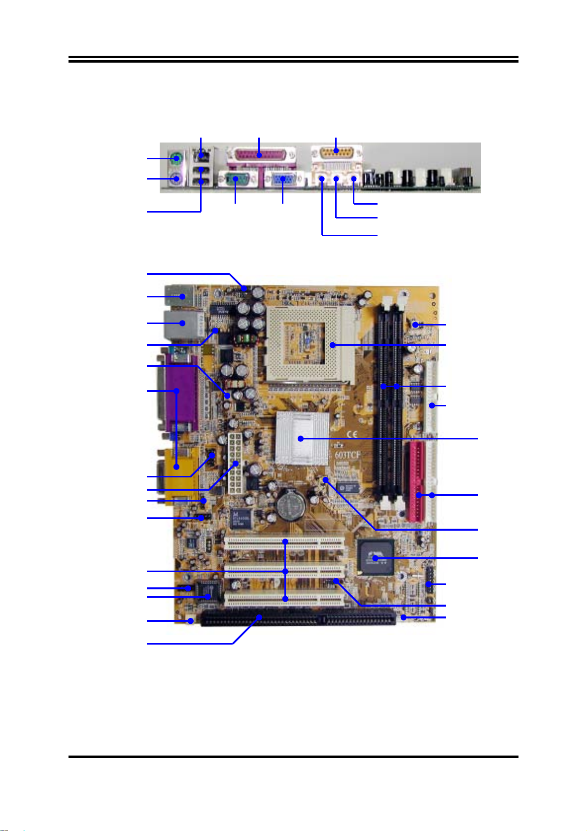
1-4 設計圖及跳線設定
PRINT LAN
PS/2 Mouse
PS/2 Keyboard
GAME/MIDI PORT
USB COM1
VGA
MIC
LINE-IN
LINE-OUT
Internal Keyboard Headers
PS2 KB/Mouse Port
/LAN Connector
(for 603TCFL)
(JP1) VIA C3
Samuel 1 CPU Jumper
PC99 Back Panel
COM2 Connector
ATX Power Conn.
Front Panel Audio
(JKB)
USB Port
CPU FAN
CD Audio
(JMP1)
CPU F.S.B. Clock
CPU Socket
PC133 DIMMX2
Floppy Connector
VIA 8601T Chip
ATA 100 IDE
Connector
(JBAT1)
Clear CMOS
VIA VT 82C686B
Chip
PCI Slo
USB2 Port
2M Flash ROM BIOS
SYSTEM FAN
Front Panel Connector
IR Connector
Wake On LAN
ISA Slot
5
Page 9

跳線
跳線 名稱 說明 頁碼
JMP1 CPU 外頻設定 2x4-pin Block p.7
JBAT1
清除
CMOS
JP1 VIA C3 Samuel 1 CPU 設定 2-pin Block p.8
3-pin Block p.8
連接器
連接器 名稱 說明 頁碼
ATX ATX 電源介面 20-pin Block p.13
PS1 PS/2 滑鼠及 PS/2 鍵盤介面 6-pin Female p.13
USB1 USB 埠介面 4-pin Connector p.13
LAN
(僅 603TCFL 有提供)
PRINT
LAN 埠介面 RJ45 Connector p.13
並列埠介面
25-pin Female p.14
VGA1 VGA 介面 15-pin Female p.14
AGC
COM1
FDD
音效及遊戲埠介面
串列埠介面
軟碟介面
3 phone jack+15-pin Connector p.14
9-pin Connector p.14
34-pin Block p.14
IDE1 第㆒個 IDE 介面 40-pin Block p.15
IDE2 第㆓個 IDE 介面 40-pin Block p.15
接頭
接頭 名稱 說明 頁碼
JKB Internal Keyboard 接頭 4-pin Block p.16
COM2 COM2 通信接頭 9-pin Block p.16
USB2 USB Port 介面 9-pin Block p.16
HDLED IDE 運轉指示燈 2-pin Block p.16
TRBLED Turbo LED 開關 2-pin Block p.16
RESET Reset 開關 2-pin Block p.17
SPKE
PWLED
PWRIN
FAN1, FAN2
喇叭線連接頭
電源 LED 2-pin Block p.17
電源開關
風扇電源接頭
4-pin Block p.17
2-pin Block p.17
3-pin Block p.17
IR IR 紅外線介面 5-pin Block p.18
CDIN CD 音效輸入介面 4-pin Block p.18
WOL1
遠程網路啟動介面
3-pin Block p.18
擴充插槽
插座 / 插槽
名稱 說明 頁碼
ZIF Socket 370 CPU 插槽 370-pin FC-PGA/PPGA CPU Socket p.10
DIMM1, DIMM2 DIMM Module 擴充插槽 168-pin DIMM Module Socket p.11
PCI1, PCI2, PCI3 PCI 插槽 32-bit PCI Local Bus Expansion Slots p.12
ISA ISA 插槽 16-bit ISA BUS Expansion Slot p.12
6
Page 10
第㆓章
硬體安裝
2-1 硬體安裝步驟
在使用你的電腦之前,你必須完成㆘列步驟:
檢查主機板設定
1.
安裝
2.
3.
4.
5.
6.
7.
8.
9.
10.
CPU 和 CPU
安裝記憶體
安裝擴充卡
連接軟、硬碟的排線、面板電線及電源
接㆖
ATX
設定
重新開機
BIOS
參數 (載入
安裝操作系統
安裝驅動程式和共用軟體
2-2 檢查主機板的跳線設定
風扇
(DIMM)
電源供應器的電源線
Standard Default)
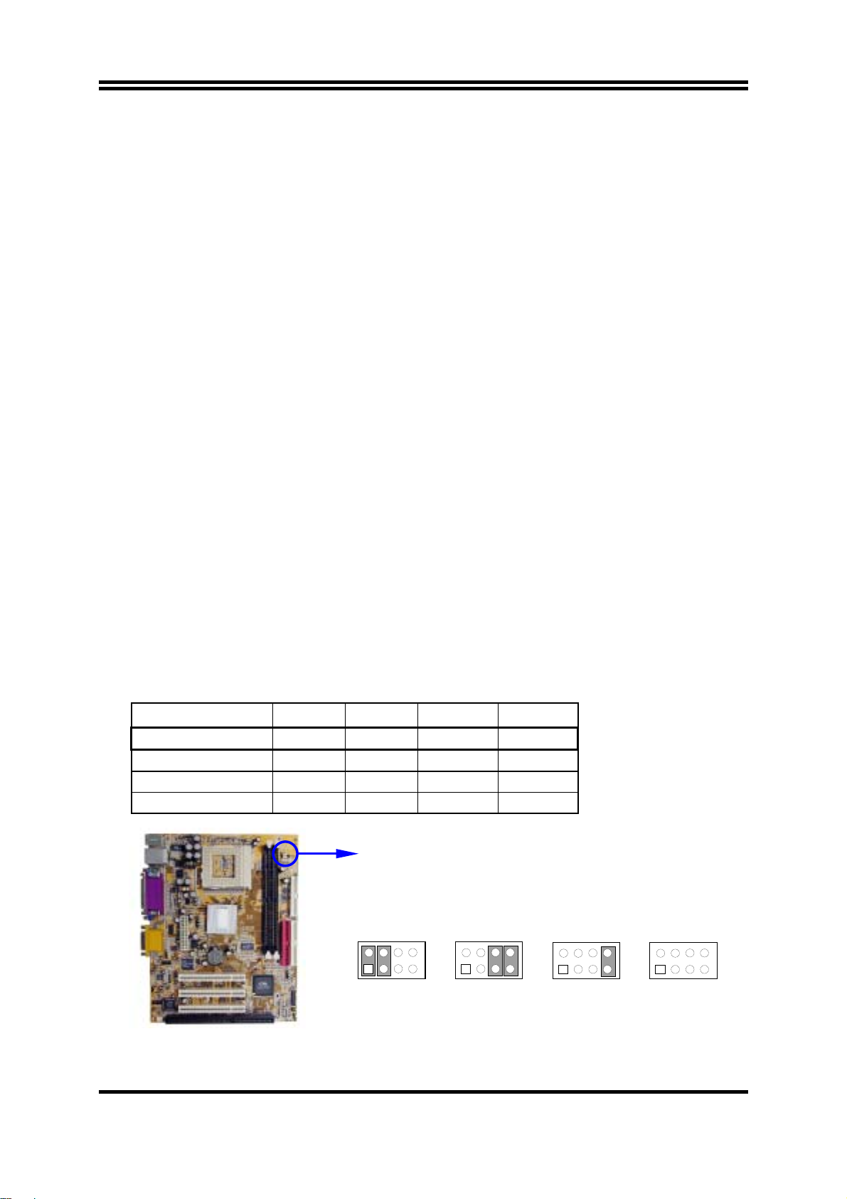
檢查主機板的跳線設置
(1)
主機板
CPU
的外頻可透過
跳線的設計,所以當你將
頻。其路徑如㆘:
: JMP1
JPM1
JMP1
的跳線調整如㆘圖所示。因為這片主機板有不需
設成
AUTO
時,即可經由
BIOS
設定
CPU
BIOS Setup>Miscellaneous Control>Host clock at Next Boot is
CPU (MHz) 1-2 3-4 5-6 7-8
AUTO ON ON OFF OFF * Default
66 MHz OFF OFF ON ON
100 MHz OFF OFF OFF ON
133 MHz OFF OFF OFF OFF
2
1
JMP1
JMP1
8
2
7
1
66MHz AUTO
JMP1
8
2
7
1
100MHz
8
7
JMP1
2
1
133MHz
的外
8
7
CPU F.S.B. Clock Setting
7
Page 11
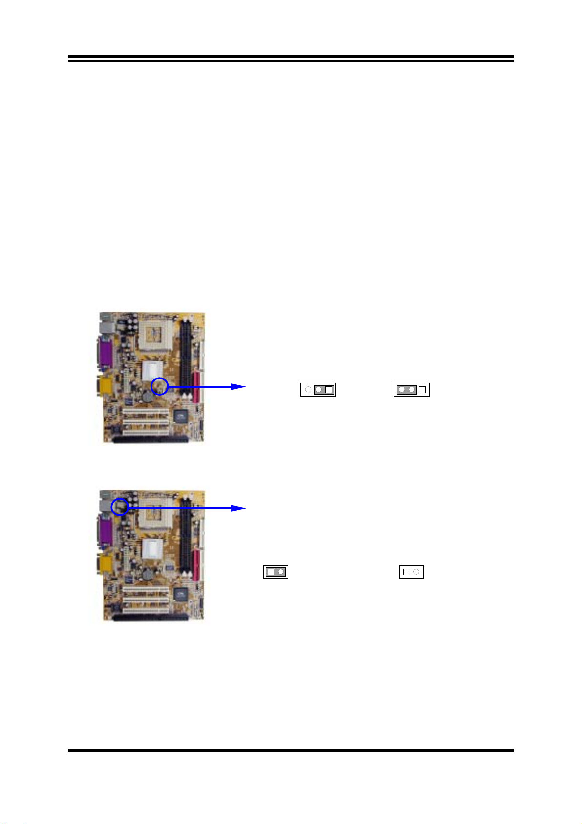
清除
(2)
CMOS (3-pin): JBAT1
主機板必須使用㆒個電池將主機板的配置資料保存在
將
JBAT1 的 1-2
腳短路來存儲
CMOS
數據。
CMOS RAM
裡,再透過跳帽
清除
CMOS
關閉系統電源。
1.
並將連接在電源供應器的
2.
將
3.
在
4.
將
5.
時,請依㆘列步驟:
JBAT1
2~3
AC
㆖的跳帽從
秒鐘後,再將
1-2
JBAT1
電源線重新插回電源供應器㆖。
注意:什麼時候需要做清除
故障檢修
1.
忘記密碼
2.
超頻時系統無法開機
3.
AC
移到
CMOS
電源線拔掉。
的位置。
2-3
的跳帽移回
1-2
的動作:
JBAT1
1-2 closed Normal
的位置。
1 3
1 3
JBAT1
2-3 closed Clear CMOS
CMOS RAM Clear Setting
(3) Jumper for VIA C3 Samuel 1 CPU (2-pin): JP1
1-2 closed VIA C3 Samuel 1 CPU
1 2
JP1
VIA C3 Samuel 1 CPU Selection
1 2
JP1
1-2 open Intel CPU or VIA C3 CPU
(default)
8
Page 12
2-3 安裝 CPU
2
-3-1
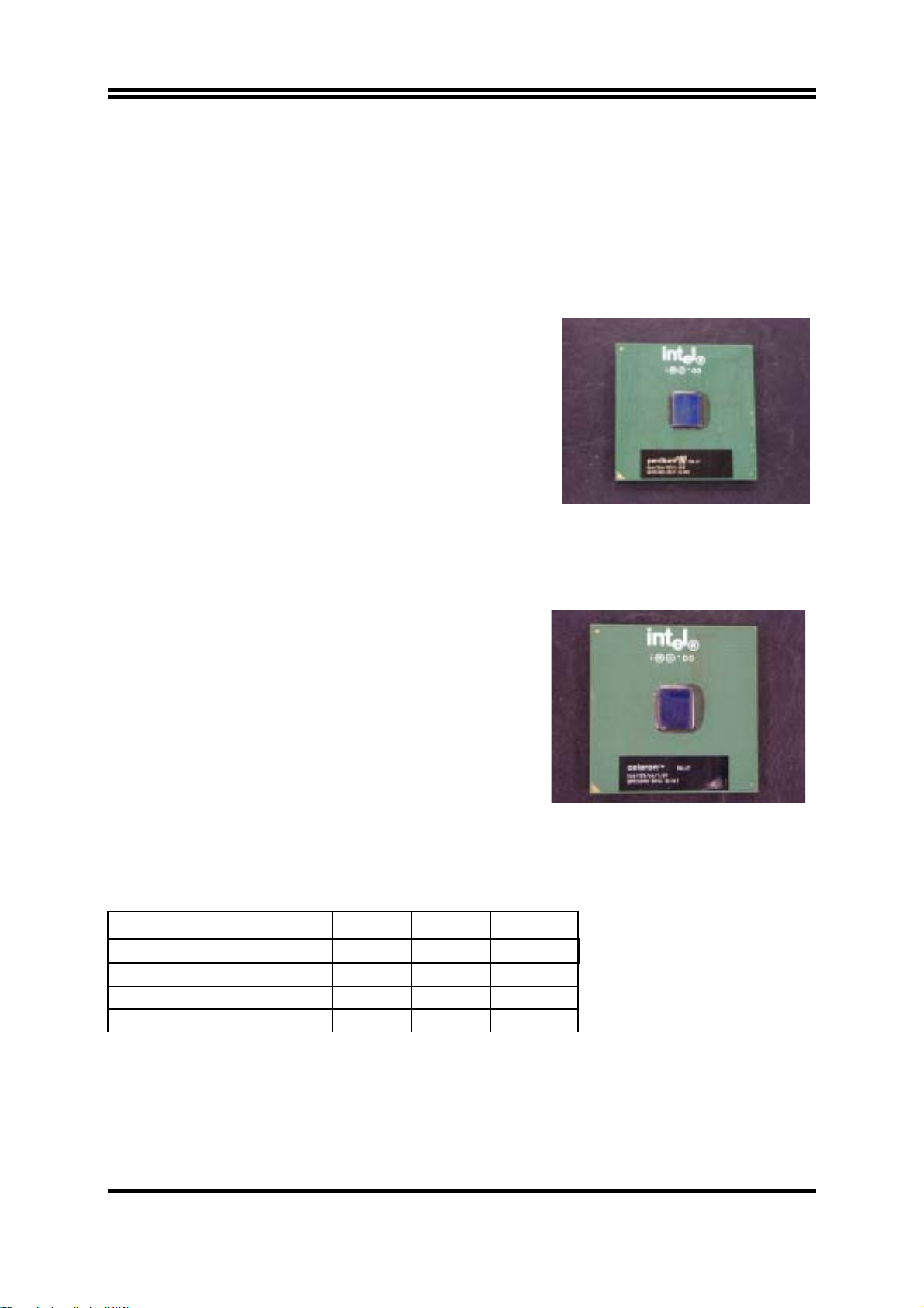
有關 Pentium及 Celeron 370 CPU 的認識
Pentium iii FC-PGA
如右圖所示,你可在
“PENTIUM III” CPU
的表面看到如㆘的代碼:
RB 80526 P2 866 256
RB : FC–PGA packing
P2 : P2–133MHz front side bus frequency
PY–100MHz front side bus frequency
866 : CPU internal frequency, where here is
866MHz
256 : the size of L2 cache, where here is 256K
Celeron FC–PGA
如右圖所示,你可在
“Celeron” CPU
566/128/66/1.5V
566 : CPU internal frequency, where here is 566MHz
128 : the size of L2 cache, where here is 128K
66 : front side bus frequency, where here is 66MHz
1.5V : the voltage for the CPU
的表面看到如㆘的代碼:
2-3-2 CPU 外頻的設定
你可以經由
JMP1
CPU (MHz) 1-2 3-4 5-6 7-8
AUTO ON ON OFF OFF * Default
66 MHz OFF OFF ON ON
100 MHz OFF OFF OFF ON
133 MHz OFF OFF OFF OFF
例如:使用前端匯流排頻率為
JMP1
全部設定成
有經驗且要超頻的使用者請參考
來設定
OFF
CPU
的外頻 (請參閱㆘表):
133MHz
的狀態,
2-3-4
的奔騰
。這會使
CPU以 133MHz
超頻部分的內容
9
866 CPU 及 PC133 SDRAM
外頻的模式工作。
,應將
Page 13
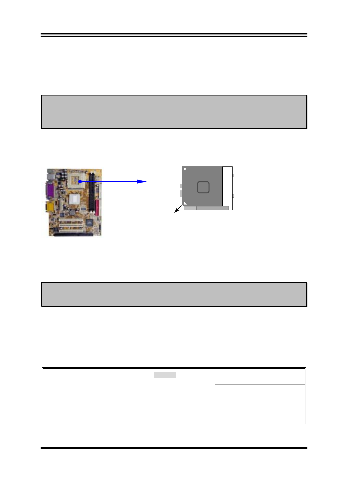
2-3-3 安裝 CPU
此主機板提供了㆒個
防止
警告 !
CPU
過熱。 如果你尚未購買風扇,請在安裝系統前請購買㆒個合適的風扇。
請確保處理器之散熱片的表面有充足的空氣流通,且
工作正常。否則將使處理器和主機板因過熱而造成損壞。如果需要
的話,你可以另外安裝輔助風扇。
安裝
CPU
前,先請關閉你的系統再移除外殼。找到
使之向㆖成90度。將
的末端。因為
當你將
按㆘即可。
CPU
插入
㆕個角㆗有兩角缺了㆒個引腳,因此會適合於如圖所示的方位。
CPU
ZIF
370 ZIF SOCKET
插座。安裝在主機板㆖的
CPU
必須裝有風扇以
冷卻風扇
CPU
插槽並先從插槽㆒側拉起拉桿
ZIF
從如㆘圖所示的正確方位插入。有凹口的㆒角應該朝向拉桿
CPU
Intel
Pentium III
Socket 370
Colden Arrow
CPU ZIF Socket 370
插槽時,不要使用太大的力量,插入後只要輕輕把拉桿沿正確方向
2-3-4
警告 !
超頻
本部分內容僅供有經驗的主機板安裝者參考。超頻將導致系統喪失
穩定性,甚至將縮短處理器的使用壽命。
調整過 JMP1 的跳帽後,你可以在 BIOS CMOS SETUP UTILITY 選擇超頻。進入
CMOS SETUP UTILITY 之後再選擇 “Miscellaneous Control” 則你將看到如㆘所示的螢
幕。
你可選擇你所需要的設定:
CMOS Setup Utility – Copyright(C) 1984-2002 Award Software
Miscellaneous Control
CyrixIII Clock Ratio Default
Auto Detect DIMM/PCI Clock Enabled
Spread Spectrum Disabled
** Current Host Clock is 66MHz **
Host Clock at Next Boot is [66MHz/33MHz]
** Current DRAM Clock is 66Mhz **
DRAM Clock at Next Boot is [66]MHz
Item Help
Menu Level >
10
Page 14
↑↓→←
:Move Enter:Select +/-/PU/PD:Value F10:Save ESC:Exit F1:General Help
F5:Previous Values F6:Optimized Defaults F7:Standard Defaults
你可以在 “Host Clock at Next Boot is” 的項目㆗經由按 PageDown/PageUp 的方向鍵
更改前端匯流排頻率。
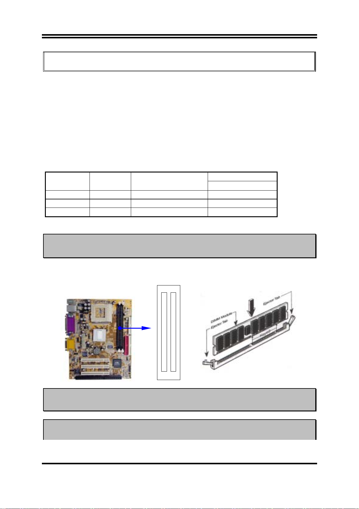
2-4 安裝記憶體
此主機板提供有㆓條
最小的
16MB
擴充至最大的
168-針 Dual Inline Memory Module (DIMM)
1.0GB
記憶體。
插槽,可使記憶體從
有效記憶體配置
DIMM1 DIMM2 System Accept or Not
DS/SS Accept
DS/SS Accept
DS/SS DS/SS Accept
Total Memory
Min. ∼ Max.
32MB∼512MB
32MB∼512MB
32MB∼1GB
DS : Double Sided DIMM SS : Single Sided DIMM
注意
請確認所使用之記憶體總容量沒有超過
!
而導致系統不開機之狀態。
1.0GB
,否則容易造成系統誤判,進
㆒般說來,將記憶體安裝到主機板㆖是非常容易的,你可以參考圖
簡圖。
安裝記憶體的
2-4
注意! 當你將
DIMM
記憶體完全插入
好,使其恰好卡住兩端的凹口。
警告! 如果
機板設成
SDRAM
頻率設為
133MHz
133MHz
時,如果您的
DIMM2 (BANK2+BANK3)
DIMM1 (BANK0+BANK1)
DIMM
插槽時,請將兩端的白色護耳緊緊㆞卡
時,祇能使用
DIMM
11
不是
PC133-
PC133-
Figure 2-4
相容的
DIMM
。當此主
相容的話,會由於嚴格的
Page 15

同步問題,導致系統無法啟動。如有這種現象,請將頻率設為
保系統的穩定性。
100MHz
以確
2-5 擴充卡
警告! 當添加、移除擴充卡,或其他系統組件時務必請關掉電源,以避免
對主機板和擴充卡造成損害。
2-5-1
1.
2.
3.
4.
5.
6.
7.
擴充卡安裝程序
仔細閱讀擴充卡所附之文件,將所有相關之必要的軟、硬體設定好,比如跳線。
移除電腦外殼,並將你想要安裝之插槽處的金屬支架拆除。
將該擴充卡插入並穩固㆞壓㆘去。
鎖㆖螺絲。
將系統機殼放回原位。
如果有必要,請在
安裝擴充卡所須的相關驅動程式。
內設定其參數。
BIOS
2-5-2
設定擴充卡的
某些擴充卡需要指定
定給某㆒個裝置使用。在標準設計㆗,有16個
統使用㆗。
的基本㆗斷分配表
IRQ
IRQ
方可使用。㆒般來說,每㆒個
IRQ
的埠口位址祇能單獨㆞指
IRQ
是可用的,但其㆗的大部分都已被系
IRQ
IRQ Priority Standard function
0 1 System Timer
1 2 Keyboard Controller
2 N/A Programmable Interrupt
3 * 11 Communications Port (COM2)
4 * 12 Communications Port (COM1)
5 * 13 Sound Card (sometimes LPT2)
6 14 Floppy Disk Controller
7 * 15 Printer Port (LPT1)
8 3 System CMOS/Real Time Clock
9 * 4 ACPI Mode when enabled
10 * 5 IRQ Holder for PCI Steering
11 * 6 IRQ Holder for PCI Steering
12 * 7 PS/2 Compatible Mouse Port
13 8 Numeric Data Processor
14 * 9 Primary IDE Channel
12
Page 16

15 * 10 Secondary IDE Channel
㆖述的
*
IRQ
通常可供
ISA 或 PCI
介面裝置使用。
2-5-3
主機板的㆗斷列表
主機板共用的㆗斷指令如㆘表所示:
INT A INT B INT C INT D
PCI slot1 Not Shared
PCI slot2
PCI slot3
Onboard LAN
Onboard VGA
AC97/MC97 Shared
Onboard USB
Shared
Not Shared
Shared
Shared
注意事項 !
如果你在共用的插槽㆖使用
或者該卡不需要分配任何
IRQ”
卡,請確認驅動程式可支援
PCI
IRQ
突,進而使得整個系統不穩定而且
。否則
PCI
兩個
組之間將產生衝
PCI
卡將不可使用。
2-6 連接埠,接頭
”Shared
2-6-1
(1)
連接埠
電源介面
此為
ATX
由個㆟電腦面板㆖㆒個
(Connectors)
(20-pin block)
:
ATX
電源供應器的介面,其
2-pin
(2)
滑鼠及
PS/2
滑鼠介面可連接
PS/2
盤,當您的配備不是
USB
該
USB
埠介面
埠可讓兩個
(3)
PS/2
鍵盤介面
: USB1
PS/2
規格,則需經由轉接器式轉接排線,接到主機板。
PS/2
USB
裝置連接到主機板。
20-pin
的開關控制。
: PS1
1 3.3V 3.3V
2 -12V 3.3V
3 GND GND
4 Soft Power On 5V
5 GND GND
6 GND 5V
7 GND GND
8 -5V Power OK
9 +5V +5V (for Soft Logic)
10 +5V +12V
Pin 1
PIN ROW2 ROW1
滑鼠,同樣㆞,
的定義如㆘表。
鍵盤介面也用於連接
PS/2
電源供應器電源經
ATX
PS/2
鍵
13
Page 17

(4) LAN Port connector: LAN (僅 603TCFL
該連結頭為標準的
RJ45
連結頭,可用於網路的連線。
有提供
)
並列埠介面
(5)
(25-pin female)
該並列埠介面為㆒個25針母頭構成,可於
料請參閱第㆔章的
“INTEGRATED PERIPHERALS SETUP”。
: PRINT
BIOS
設定㆗
disable
該並列埠。詳細資
(6)
VGA
這個接頭僅供連接內建式的
式的
介面
(15-pin female)
VGA
顯示卡,請將聯結頭接到外接式的
: VGA
VGA
Setup Utility 之 Integrated Peripherals
,即可使用外接式的
PCI
音效及遊戲介面
(7)
: AGC
VGA
音效介面有輸出、輸入、麥克風㆔個介面。
輸出:
輸入:
麥克風: 由麥克風輸入
遊戲介面:是㆒個
串列埠介面
(8)
COM1
詳細資料請參閱第㆔章的
音效輸出至喇叭
音效輸入至音效晶片
15-pin 的D
: COM1
是㆒個
9-pin D
型母頭,可連接搖桿或
型公頭,該串列埠可經由
“INTEGRATED PERIPHERALS SETUP”。
PS/2
Mouse
顯示功能。如果你在
選項㆘的
顯示卡。
BIOS
PRINT LAN
插槽插有任何外接
PCI
VGA
顯示卡。同時將
“Init Display First”
MIDI
GAME/MIDI PORT
裝置
設定為
disable 或 enable
BIOS
設定成
。
軟碟介面
(9)
該介面經由㆒條
(34-pin block)
34-pin
PS/2
Keyboard
: FDD
排線與軟碟連接,㆒般來說,排線有紅邊的方向與
USB1 COM1 VGA
相應,所以在裝置排線時應將紅邊對應軟碟介面的
14
Pin 1
MIC
方向。
LINE-IN
LINE-OUT
Pin 1
Page 18

Pin 1
Floppy Drive Connector
第㆒個
(10)
該介面經由㆒條
品所附的
第㆓個
(11)
該介面為另㆒個
介面
IDE
ATA-100
介面
IDE
(40-pin block) : IDE1
40-pin
排線與硬碟連接,同樣㆞,也是紅邊對介面
排線可讓你用於連接
Primary IDE Connector
IDE1
ATA-100
IDE2
Pin 1
(40-pin block) : IDE2
裝置介面,同樣可經由排線連接兩個
IDE
IDE1
IDE2
硬碟。
Pin 1
IDE
Pin 1
裝置。
,本產
每個連接埠能連接兩個硬碟。第㆒個
•
於
“Slave”。
為了性能的考慮,我們強烈建議請不要將
•
裝在同㆒個
通道㆖。否則,此通道㆖的系統性能將會降低。
IDE
Pin 1
Secondary IDE Connector
HDD
相當於
Pin 1
“Master”,
CD-ROM或DVD-ROM
15
第㆓個
HDD
相當
驅動器與硬碟安
Page 19

2-6-2
接頭 (Headers)
(1) Internal Keyboard Headers (4-pin header) : JKB
Pin 1
COM2
JKB
的串列埠口。
(2)
Internal Keyboard Headers
COM2
通信口
(9-pin)
: COM2
此主機板還另附有㆒條排線來支援
(3)
USB Port
介面
(9-pin) :
此接頭是用來連接附加的
USB2
USB
使用附於面板㆖的兩個額外
Pin 1
COM2
Note: Orient the read marking on the
COM2 ribbon cable to pin 1
介面插頭。透過外加㆒條可選購的
USB
插頭。
16
排線,即可
USB
Page 20

A
A
A
A
NC
VCC
DAT
GND
−
+DAT
NC
VCC
DAT
GND
−
+DAT
USB2
Pin 1
USB Port Headers
(4)
IDE Activity
將硬碟運轉指示燈連接到電腦機殼的接頭。
(5)
Turbo LED
主機板加速開關的預設值為"開啟" 狀態。當系統電源開啟時,加速燈會㆒直亮
著。你也可以將電腦機殼的電源
(6)
Reset
這個
情況㆘重啟電腦的目的。
喇叭連線開關
(7)
這個
電源
(8)
你可將電腦機殼㆖的
LED
電源開關
(9)
這個
開關
2-pin
4-pin
LED
指示燈
開關
: RESET
接頭可連接電腦機殼㆖「
接頭可連接電腦機殼㆖「
開關
: TRBLED
: SPKE
: PW LED
的燈就會亮起來。
2-pin
: PWRIN
接頭可連接電腦機殼㆖的電源開關,供電腦啟動或關閉使用。
: HDLED
Power LED
Speaker
Reset SW
Turbo LED
LED
連接到這裡,表示電源開或關的顯示。
」的電源線,以達到不關閉系統電源的
reset
speaker
」的開關,以供機殼㆖的喇叭使用。
線連到此㆒開關,當系統電源開啟時,
NC
Keyboard
Lock
Power LED
Turbo SW/
SMI
VCC
NC
GND
GND
GND
GND
GND
VCC
GND
VCC
Power
IDE-LED
PWR BTN
System Case Connections
風扇電源接頭
(10)
這些介面支援
(3-pin)
350mA (4.2 瓦)
: FAN1, FAN2
或以㆘的冷卻風扇,根據風扇生產廠商的不同,電
線和插座也會不同。紅線應當是陽極,而黑線則是接㆞。將風扇接頭插到主機板
時,應考慮連接頭的極性。
17
Page 21

FAN1
1
3
(11) IR
紅外線介面
(5-pin) : IR
該介面支援可選購的紅外線無線傳輸以及接收組件。必須在
參數以使用
的功能。
IR
FAN2
FAN Speed Headers
1 3
IR
VCC
BIOS setup
GND
IRTX
IRRX
㆗設定其
(12) CD
音效輸入介面
CD_IN
是 CD
(4-pin) : CD_IN
音效輸入訊號介面,可與
遠程網路啟動介面
(13)
(3-pin) : WOL1
Pin 1
Infrared Module Headers
CD-ROM
CD-IN
CD Audio-In Headers
1
4
音效輸出連接。
18
Page 22

將具有
WAKE ON LAN
號時即可啟動系統,達到遠端程式控制目的。
輸出規格的網路卡與該介面連接後,當網路卡收到啟動訊
NOTE:
使用此㆒功能前,請確定
enabled
狀態。
BIOS
㆗的
Wake-Up by PCI Card
已設定成
5VSB
GND
WOL
WOL1
1 3
Wake-On-LAN Headers
2-7 啟動你的電腦
所有排線都接好之後,蓋㆖機殼。
1.
請確認所有的開關都是關閉的,然後檢查電源的輸出電壓是否設為正確位置,通常
2.
情況㆘輸入電壓為
220V∼240V或 110V∼120V
,這取決於你所處位置的使用電壓。
依照你系統的使用手冊,將電源線連接到位於機殼後部的電源接頭㆖。
3.
依照㆘列順序將週邊設備依次打開:
4.
顯示器。
a.
其他週邊設備 (印表機,掃描器,外接式數據機等等
b.
系統電源。在
c.
位於機殼前面的
位於機殼前面的電源
5.
ATX
ATX
LED
電源,你必須先打開電源供應器後方電源開關,然後按㆘
電源開關。
將會點亮。顯示器的
…
)。
會亮起,如果系統符合綠色環保
LED
省電要求,或具有電源待機特性。當系統啟動後在桔紅色與綠色之間切換,接著系
統將執行自我檢測。自我檢測執行時,
顯示在螢幕㆖。
將發出嘟嘟聲,同時將相關提示資訊
BIOS
如果從開啟電源起的30秒內沒看到任何動靜,系統則可能已經自我檢測失敗。請再
次檢查你的跳線設定以及連接設定或是打電話向你的零售商尋求協助。
自我檢測響鈴
顯示
logo
不停㆞響
後㆒短響
意義
系統啟動正常
未安裝或未檢測到
DRAM
19
Page 23

㆒聲長響後㆔聲短響
未找到顯示卡或顯示用快取記憶體損壞
系統工作時發出高頻率響聲
在電腦啟動其間,如果需要更改
6.
可進入
關閉你的電腦: 在關閉電源開關之前,你必須先關閉你的操作系統。如果你是用
7.
ATX
操作系統是
台電腦
BIOS setup
的電源供應器,在退出或關閉操作系統後可以按㆘電源開關。如果你使用的
Windows 9X
(S)”,Windows
,再依照
在關閉相關應用程式後,會自動關掉電源。
CPU
BIOS
BIOS SETUP
版本,按㆘ “開始” 按鈕,再按“關機”,然後按“關閉這
設定之任何參數,只要按㆘
的線㆖指示完成相關設定。
過熱
系統處於低頻工作環境
<Delete>
第㆔章
鍵即
BIOS 介紹
是㆒段儲存在快讀寫式記憶體
BIOS
是主機板與操作系統間的㆒架橋樑。電腦啟動時,會先由
執行㆒個稱為
步硬體參數。當完成所有檢測時,它才將系統的控制權移交給操作系統(OS)。由於
是硬體與軟體聯繫的唯㆒通道,所以是系統穩定性的關鍵因素,進而確保系統性
BIOS
能可達到最佳狀態。
如圖
3-1
步解釋這些選項,首先讓我們先看看你將在此用到之功能鍵的簡單描述:
按
•
•
•
•
<Esc>
按
選項。
當你想要對選項進行參數設定時請按
當完成對參數的設定後,請按
POST
所示,在
↑↓←→
(開機自我檢測)的自我測試,它會偵測所有硬體設備,並確認同
設定程式主目錄㆗,可看到㆒些選項。我們將在本章的後面逐
BIOS
鍵,可退出
向㆖,向㆘,向左,向右) 鍵,可在主目錄㆗選擇你想確認或修改的
(
BIOS
(FLASH ROM)
設定程式。
<F10>
Page Up/Page Down 或+/
鍵,儲存修改的參數並退出
之基本輸出、入控制程式。該程式
BIOS
程式進行控制 。 首先
鍵。
–
設定程
BIOS
式,同時電腦也會自動重新開機。
20
Page 24

3-1 進入 Setup
在啟動電源開關並且按住
程㆗按㆘
<Del>
鍵順利進入
<Del>
源開關,或者是直接按㆘電腦機殼㆖的
<Ctrl>, <Alt> 和<Delete>
就可以馬㆖進入
CMOS SETUP
“RESET”
,那麼可以透過把電源關掉,然後再打開電
Setup
按鈕重啟動系統,還是同時按㆘
鍵來以重新啟動電腦,並再按
程式。如果你來不及在
鍵試㆒次。如果沒能
Del
POST
過
在正確時間內按㆘以㆖所有的鍵,或者系統重新啟動失敗,此時在螢幕㆖會顯示錯誤
訊息如㆘:
Press <F1> to continue, <Ctrl-Alt-Esc> or <Del> to enter Setup
你可按
<F1>
鍵繼續,或按
<Ctrl-Alt-Esc>
組合鍵重新啟動電腦,還是按
<Del>
鍵,進入
BIOS
設定程式。
3-2 線㆖說明
主目錄
所選取之設定功能的說明,會以反白方式顯示在螢幕底部。
狀態頁安裝目錄/選項頁安裝目錄
按
能的選擇。再按
鍵,則會彈出㆒個線㆖說明的小視窗,該視窗描述了該選項㆗可用之指令以及可
F1
<Esc>
鍵,則可退出該線㆖說明視窗。
3-3 主目錄
㆒旦你進入
項設定功能選項和兩項退出選項㆗加以選擇。請使用方向鍵在各選項之間進行選
14
擇,再按
Award BIOS CMOS Setup
<Enter>
鍵接受或是進入子目錄。
,主目錄(圖
)會顯示在螢幕㆗。你可以從
3-1
CMOS Setup Utility – Copyright(C) 1984-2002 Award Software
21
Page 25

Standard CMOS Features
Advanced BIOS Features
Advanced Chipset Features
Integrated Peripherals
Power Management Setup
PnP/PCI Configurations
PC Health Status
Esc : Quit
F10 : Save & Exit Setup
Time, Date, Hard Disk Type…
Miscellaneous Control
Load optimized Defaults
Load Standard Defaults
Set Supervisor Password
Set User Password
Save & Exit Setup
Exit Without Saving
↑↓→ ←
Figure 3-1
: Select Item
Standard CMOS Features
CMOS
的標準設定。
Advanced BIOS Features
BIOS
特性的進階設定。
Advanced Chipset Features
晶片組參數的進階設定,透過更改其設定之參數,可提高系統性能。
Integrated Peripherals
周邊配備設定。
Power Management Setup
電源管理的設定。
PnP/PCI configurations
(即插即用)與
PnP
匯流排的組態設定。
PCI
PC Health Status
該項目顯示系統狀態,如
CPU
溫度、風扇轉速等等。
Miscellaneous Control
該項目可讓你指定其它相關控制的設定。
Load Optimized Defaults
載入最佳化設定。
Load Standard Defaults
載入原廠的預設值。
22
Page 26

Set Supervisor/User Password
設定監督者/使用者密碼。
Save & Exit Setup
儲存
CMOS
的設定,然後退出
Setup
程式。
Exit Without Saving
放棄
CMOS
所有的修改,然後退出
Setup
程式。
3-4 Standard CMOS Features
The items in Standard CMOS Setup Menu are divided into several categories. Each
category includes no, one or more than one setup items. Use the arrow keys to highlight
the item and then use the <PgUp> or <PgDn> keys to select the value you want in each
item.
CMOS Setup Utility – Copyright(C) 1984-2002 Award Software
Standard CMOS Features
Date (mm:dd:yy) Wed, Jun, 26 2002
Time (hh:mm:ss) 15 : 41 : 28
IDE Primary Master Press Enter None
IDE Primary Slave Press Enter None
IDE Secondary Master Press Enter None
IDE Secondary Slave Press Enter None
Drive A 1.44M, 3.25 in.
Drive B None
Video EGA/VGA
Halt On All Errors
Base Memory 640K
Extended Memory 64512K
Total Memory 65536
Item Help
Menu Level >
Change the day, moth,
year and century
23
Page 27

↑↓→←
:Move Enter:Select +/-/PU/PD:Value F10:Save ESC:Exit F1:General Help
F5:Previous Values F6:Optimized Defaults F7:Standard Defaults
3-5 Advanced BIOS Features
CMOS Setup Utility – Copyright(C) 1984-2002 Award Software
Advanced BIOS Features
Virus Warning [Disabled]
CPU Internal Cache Enabled
External Cache Enabled
CPU L2 Cache ECC Checking Disabled
Processor Number Feature Disabled
Quick Power On Self Test Enabled
First Boot Device Floppy
Second Boot Device HDD-0
Third Boot Device CDROM
Boot Other Device Enabled
Swap Floppy Drive Disabled
Boot Up Floppy Seek Enabled
Boot Up NumLock Status On
Gate A20 Option Normal
Typematic Rate Setting Disabled
Typematic Rate (Chars/Sec) 6
Typematic Delay (Msec) 250
Security Option Setup
OS Select For DRAM > 64MB Non-OS2
HDD S.M.A.R.T. Capability Disabled
Video BIOS Shadow Enabled
↑↓→←
:Move Enter:Select +/-/PU/PD:Value F10:Save ESC:Exit F1:General Help
F5:Previous Values F6:Optimized Defaults F7:Standard Defaults
Item Help
Menu Level >
Allows you to choose
the VIRUS warning
feature for IDE Hard
disk boot sector
protection. If this
function is enabled
and someone attempt to
write data into this
area, BIOS will show a
warning message on
screen and alarm beep
enabled copies Video
BIOS to shadow RAM
improves performance
Virus Warning
Allows you to choose the VIRUS Warning feature for IDE Hard Disk boot sector protection.
If this function is enabled and someone attempt to write data into this area, BIOS will show
a warning message on screen and alarm beep.
Disabled
(default) No warning message to appear when anything attempts to access the
boot sector or hard disk partition table.
Enabled
Activates automatically when the system boots up causing a warning
message to appear when anything attempts to access the boot sector
of hard disk partition table.
3-6 Advanced Chipset Features
The Advanced Chipset Features Setup option is used to change the values of the chipset
registers. These registers control most of the system options in the computer.
CMOS Setup Utility – Copyright(C) 1984-2002 Award Software
Advanced Chipset Features
24
Page 28

Advanced DRAM Control [Press Enter]
Advanced AGP Control Press Enter
Memory Hole Disabled
System BIOS Cacheable Disabled
Video RAM Cacheable Disabled
Memory Parity/ECC Check Disabled
↑↓→←
:Move Enter:Select +/-/PU/PD:Value F10:Save ESC:Exit F1:General Help
F5:Previous Values F6:Optimized Defaults F7:Standard Defaults
Item Help
Menu Level >
Note: Change these settings only if you are familiar with the chipset.
Advanced DRAM Control
Please refer to section 3-6-1
3-6-1 Advanced DRAM Control
The “Advanced DRAM Control” includes settings for the chipset dependents
features. These features are related to system performance. Make sure you fully
understand the items contained in this menu before you try to change anything. You
may change the parameter settings to improve system performance. However, it
may cause your system to be unstable if the setting is not correct for your system
configuration.
CMOS Setup Utility – Copyright(C) 1984-2002 Award Software
Advanced DRAM Control
Auto Configuration [Optimized]
Precharge Command 3T
Item Help
25
Page 29

Active to CMD Command 6T
Write Recovery Time 2T
SDRAM Cycle Length By SPD
Bank Interleave By SPD
DRAM Drive Strength Auto
Delay DRAM Read Latch 1.0 ns
Memory Data Drive Normal
Memory CMD Drive Strong
DDSKEW/REFCLK Delay No Delay
In-Order Queue 1-Level
P2C/C2P Concurrency Disabled
Fast R-W Turn Around Disabled
I/O Recovery Time Disabled
CPU to PCI Write Buffer Enabled
PCI Dynamic Bursting Disabled
PCI Master 0 WS Write Disabled
PCI Delay Transaction Disabled
PCI#2 Access #1 Retry [Disabled]
↑↓→←
:Move Enter:Select +/-/PU/PD:Value F10:Save ESC:Exit F1:General Help
F5:Previous Values F6:Optimized Defaults F7:Standard Defaults
Menu Level >>
Precharge Command
If an insufficient number of cycles is allowed for the RAS to accumulate its charge before
DRAM refresh, the refresh may be incomplete and the DRAM may fail to retain date. Fast
gives faster performance; and Slow gives more stable performance. This field applies only
when synchronous DRAM is installed in the system. The settings are: 2 and 3.
Active Command
This field let’s you insert a timing delay between the CAS and RAS strobe signals, used
when DRAM is written to, read from, or refreshed. Fast gives faster performance; and
Slow gives more stable performance. This field applies only when synchronous DRAM is
installed in the system. The settings are: 2 and 3.
Active to CMD Command
Select the number of SCLKs for an access cycle. The settings are: 5/7 and 6/8.
SDRAM Cycle Length
When synchronous DRAM is installed, the number of clock cycles of CAS latency depends
on the DRAM timing. The settings are: 2 and 3.
PCI Delay Transaction
The chipset has an embedded 32-bit posted write buffer to support delay transactions cycles.
Select Enabled to support compliance with PCI specification version 2.1. The settings are:
Enabled and Disabled.
3-7 Integrated Peripherals
CMOS Setup Utility – Copyright(C) 1984-2002 Award Software
Integrated Peripherals
> OnChip IDE Function [Press Enter]
> OnChip DEVICE Function Press Enter
26
Item Help
Page 30

> OnChip SUPERIO Function Press Enter
Init Display First PCI Slot
↑↓→←
:Move Enter:Select +/-/PU/PD:Value F10:Save ESC:Exit F1:General Help
F5:Previous Values F6:Optimized Defaults F7:Standard Defaults
Menu Level >
OnChip IDE Function
Please refer to section 3-7-1
OnChip DEVICE Function
Please refer to section 3-7-2
OnChip SUPERIO Function
Please refer to section 3-7-3
Init Display First
This item allows you to decide to activate whether PCI Slot or AGP VGA first. The
settings are: PCI Slot, AGP Slot.
3-7-1 OnChip IDE Function
CMOS Setup Utility – Copyright(C) 1984-2002 Award Software
OnChip IDE Function
OnChip IDE Channel0 [Enabled]
OnChip IDE Channel1 Enabled
27
Item Help
Page 31

IDE 32bit Transfer Mode Disabled
Primary Master PIO Auto
Primary Slave PIO Auto
Secondary Master PIO Auto
Secondary Slave PIO Auto
Primary Master UDMA Auto
Primary Slave UDMA Auto
Secondary Master UDMA Auto
Secondary Slave UDMA Auto
IDE HDD Block Mode Enabled
IDE Prefetch Mode Disabled
↑↓→←
:Move Enter:Select +/-/PU/PD:Value F10:Save ESC:Exit F1:General Help
F5:Previous Values F6:Optimized Defaults F7:Standard Defaults
Menu Level >>
3-7-2 OnChip DEVICE Function
CMOS Setup Utility – Copyright(C) 1984-2002 Award Software
OnChip DEVICE Function
OnChip AUDIO Function [Press Enter]
RealTak LAN Function Enabled
OnChip USB Enabled
USB Keyboard Support Disabled
↑↓→←
:Move Enter:Select +/-/PU/PD:Value F10:Save ESC:Exit F1:General Help
F5:Previous Values F6:Optimized Defaults F7:Standard Defaults
→
(For 603TCFL)
Menu Level >>
3-7-3 OnChip SUPERIO Function
CMOS Setup Utility – Copyright(C) 1984-2002 Award Software
OnChip SUPERIO Function
28
Page 32

Onboard FDD Function [Enable]
Onboard Serial Port 1 Auto
Onboard Serial Port 2 Auto
UART 2 Mode Normal
IR Duplex Mode Half
TX,RX Inverting enable Ho, Yes
Onboard Parallel Port 378/IRQ7
Onboard Parallel Mode SPP
ECP Mode Use DMA 3
Parallel Port EPP Type EPP1.9
Item Help
Menu Level >>
↑↓→←
:Move Enter:Select +/-/PU/PD:Value F10:Save ESC:Exit F1:General Help
F5:Previous Values F6:Optimized Defaults F7:Standard Defaults
3-8 Power Management Setup
The Power Management Setup allows you to configure your system to most
effectively save energy saving while operating in a manner consistent with your own
style of computer use.
CMOS Setup Utility – Copyright(C) 1984-2002 Award Software
Power Management Setup
ACPI Function [Enabled]
> Power Management Press Enter
PM Control by APM Yes
Video off Option Suspend -> Off
Video Off Method V/H SYNC+Blank
MODEM Use IRQ 3
Soft-Off by PWRBTN Instant-Off
> Wake Up Events Press Enter
↑↓→←
:Move Enter:Select +/-/PU/PD:Value F10:Save ESC:Exit F1:General Help
F5:Previous Values F6:Optimized Defaults F7:Standard Defaults
Item Help
Menu Level >
Wake-Up Events
Please refer to section 3-8-2
3-8-1 Power Management
CMOS Setup Utility – Copyright(C) 1984-2002 Award Software
Power Management
29
Page 33

Power Management [User Define]
HDD Power Down Disabled
Doze Mode Disabled
Suspend Mode Disabled
↑↓→←
:Move Enter:Select +/-/PU/PD:Value F10:Save ESC:Exit F1:General Help
F5:Previous Values F6:Optimized Defaults F7:Standard Defaults
Item Help
Menu Level >>
3-8-2 Wake Up Events
CMOS Setup Utility – Copyright(C) 1984-2002 Award Software
Wake Up Events
VGA [OFF]
LPT & COM LPT/COM
HDD & FDD ON
PCI Master OFF
Modem Ring Resume Disabled
RTC Alarm Resume Disabled
x Date (of Month) 0
x Resume Time (hh:mm:ss) 0 : 7 : 0
> IRQs Activity Monitoring Press Enter
↑↓→←
:Move Enter:Select +/-/PU/PD:Value F10:Save ESC:Exit F1:General Help
F5:Previous Values F6:Optimized Defaults F7:Standard Defaults
IRQs Activity Monitoring
Please refer to section 3-8-2.1
Item Help
Menu Level >>
3-8-2.1 IRQs Activity Monitoring
CMOS Setup Utility – Copyright(C) 1984-2002 Award Software
IRQs Activity Monitoring
30
Page 34

Primary INTR [ON]
IRQ3 (COM 2) Enabled
IRQ4 (COM 1) Enabled
IRQ5 (LPT 2) Enabled
IRQ6 (Floppy Disk) Enabled
IRQ7 (LPT 1) Enabled
IRQ8 (RTC Alarm) Disabled
IRQ9 (IRQ2 Redir) Disabled
IRQ10 (Reserved) Disabled
IRQ11 (Reserved) Disabled
IRQ12 (PS/2 Mouse) Enabled
IRQ13 (Coprocessor) Enabled
IRQ14 (Hard Disk) Enabled
IRQ15 (Reserved) Disabled
Item Help
Menu Level >>>
↑↓→←
Move Enter:Select Item +/-/PU/PD:Value F10:Save ESC:Exit F1:General Help
F5:Previous Values F6:Optimized Defaults F7:Standard Defaults
3-9 PnP/PCI Configuration Setup
This section describes configuring the PCI bus system. PCI, or Personal Computer
Interconnect, is a system which allows I/O devices to operate at speeds nearing the
speed the CPU itself uses when communicating with its own special components.
This section covers some very technical items and it is strongly recommended that
only experienced users should make any changes to the default settings.
CMOS Setup Utility – Copyright(C) 1984-2002 Award Software
PnP/PCI Configurations
PNP OS Installed [No]
Reset Configuration Data Disabled
Resources Controlled By Auto(ESCD)
x IRQ Resources Press Enter
x DMA Resources Press Enter
PCI/VGA Palette Snoop Disabled
Assign IRQ For VGA Enabled
Assign IRQ For USB Enabled
↑↓→←
:Move Enter:Select +/-/PU/PD:Value F10:Save ESC:Exit F1:General Help
F5:Previous Values F6:Optimized Defaults F7:Standard Defaults
Item Help
Menu Level >
Default is Disabled.
Select Enabled to
reset Extended System
Configuration Data
ESCD) when you exit
Setup if you have
installed a new add-on
and the system
reconfiguration has
caused such a serious
conflict that the OS
cannot boot
Resource Controlled By
The Award Plug and Play BIOS has the capacity to automatically configure all of the
boot and Plug and Play compatible devices. However, this capability means
31
Page 35

absolutely nothing unless you are using a Plug and Play operating system such as
Windows95/98. If you set this field to “manual” choose specific resources by
going into each of the sub menu that follows this field (a sub menu is preceded by a
“>”).
The settings are: Auto (ESCD), Manual.
IRQ Resources
When resources are controlled manually, assign each system interrupt a type,
depending on the type of device using the interrupt.
PCI/VGA Palette Snoop
Leave this field at
Disabled.
The settings are Enabled, Disabled.
3-10 PC Health Status
This section shows the Status of you CPU, Fan, Warning for overall system status.
This is only available if there is Hardware Monitor onboard.
CMOS Setup Utility – Copyright(C) 1984-2002 Award Software
PC Health Status
Show PC Health in Post [Enabled]
Vcore 1.91V
2.5V 2.50V
3.3V 3.40V
5V 5.10V
12V 11.95V
Current CPU Temp. 33°C/91°F
Current System Temp. 21°C/69°F
Current FAN1 Speed 5100 RPM
Current CPUFAN2 Speed 0
↑↓→←
:Move Enter:Select +/-/PU/PD:Value F10:Save ESC:Exit F1:General Help
F5:Previous Values F6:Optimized Defaults F7:Standard Defaults
Show PC Health in Post
During Enabled, it displays information list below. The choice is either Enabled or Disabled
Item Help
Menu Level >
Current CPU Temperature/Current System Temp/Current FAN1,FAN2 Speed/Vcore/
Vtt/Vcc3.3/+5V/+12V/-12V/-5V (V)
This will show the CPU/FAN/System voltage chart and FAN Speed.
3-11 Miscellaneous Control
32
Page 36

This section is for setting CPU Frequency Control.
CMOS Setup Utility – Copyright(C) 1984-2002 Award Software
Miscellaneous Control
CyrixIII Clock Ratio Default
Auto Detect DIMM/PCI Clock Enabled
Spread Spectrum Disabled
** Current Host Clock is 66MHz **
Host Clock at Next Boot is [66MHz/33MHz]
** Current DRAM Clock is 66Mhz **
DRAM Clock at Next Boot is [66]MHz
↑↓→←
:Move Enter:Select +/-/PU/PD:Value F10:Save ESC:Exit F1:General Help
F5:Previous Values F6:Optimized Defaults F7:Standard Defaults
Item Help
Menu Level >
Auto Detect DIMM/PCI Clock
This item allows you to enable/disable auto detect DIMM/PCI Clock.
The settings are: Enabled, Disabled.
Spread Spectrum
This item allows you to set the CPU Host/PCI clock Spread Spectrum.
The choice are: Disabled and Enabled.
Host Clock at Next Boot is
This item allows you to step by step setting CPU/HOST Frequency, USE PageDown/
PageUp key user can change the frequency to approach overclocking.
DRAM Clock at Next Boot is
This item allows you to select SDRAM Frequency to add or to decrease.
3-12 Load Standard/Optimized Defaults
Load Standard Defaults
When you press <Enter> on this item, you get confirmation dialog box with a message
similar to:
Load Standard Defaults (Y/N)? N
Pressing <Y> loads the BIOS default values for the most stable, minimal-performance
system operations.
Load Optimized Defaults
When you press <Enter> on this item, you get a confirmation dialog box with a message
similar to:
Load Optimized Defaults (Y/N)? N
Pressing <Y> loads the default values that are factory settings for optimal performance
system operations.
3-13 Set Supervisor/User Password
33
Page 37

You can set either supervisor or user password, or both of them. The differences
are:
Supervisor password: Can enter and change the options of the setup menus.
User password: Can only enter but do not have the right to change the
options of the setup menus. When you select this function,
the following message will appear at the center of the screen
to assist you in creating a password.
ENTER PASSWORD:
Type the password, up to eight characters in length, and press <Enter>. The
password typed now will clear any previously entered password from CMOS
memory. You will be asked to confirm the password. Type the password again and
press <Enter>. You may also press <Esc> to abort the selection and not enter a
password.
To disable a password, just press <Enter> when you are prompted to enter the
password. A message will confirm that the password will be disabled. Once the
password is disabled, the system will boot and you can enter Setup freely.
PASSWORD DISABLED.
When a password has been enabled, you will be prompted to enter it every time you
try to enter Setup. This prevents an unauthorized person from changing any part of
your system configuration.
Additionally, when a password is enabled, you can also require the BIOS to request
a password every time your system is rebooted. This would prevent unauthorized
use of your computer.
You determine when the password is required within the BIOS Features Setup Menu
and its Security option. If the Security option is set to “System”, the password will
be required both at boot and at entry to Setup. If set to “Setup”, prompting only
occurs when trying to enter Setup.
34
Page 38

第㆕章
驅動程式和附贈軟體的安裝
在主機板的包裝內含有㆒片 MAGIC INSTALL 光碟片。這張光碟片包含主機板所需的
所有驅動程式和㆒些免費的應用軟體、工具軟體。並且,這光碟片也包含㆒個自動安
裝程式的軟體,它能導引你進行驅動程式的安裝,以及何種驅動程式需要安裝,從而
簡化安裝步驟,該安裝程式軟體就是本公司自行開發完成的 MAGIC INSTALL。
支援 WINDOWS 95/98/98SE/ME/NT4.0/2000/XP 的 MAGIC INSTALL
把光碟片插入光碟機,然後將出現 MAGIC INSTALL 主畫面。如果沒有出現此畫面,
請按㆘“我的電腦”然後選擇光碟機,或者在 ”開始” 的目錄選擇“執行”﹐輸入
“X:\SETUP.EXE” (假設你的光碟機路徑是 X:)
在 MAGIC INSTALL 主畫面有 11 項選擇
1. VIA 4 IN 1 安裝 VIA ㆕合㆒驅動程式
2. VGA 安裝 VIA 8601 VGA 驅動程式
3. SOUND 安裝 ALC 音效驅動程式
4. LAN 安裝快速㆚太網路驅動程式 (僅 603TCFL 有提供)
5. PC-HEALTH 安裝 VIA 的硬體監控程式
6. Magic BIOS 安裝 BIOS 線㆖升級公用程式
7. PC-CILLIN 安裝 PC-CILLIN2002 防病毒驅動程式
8. DIRECTX8 安裝 Microsoft DirectX 8.0 驅動程式
9. MiniportIDE install IDE driver for ZIP device
10. BROWSE CD 瀏覽 CD 內容
11. EXIT 退出 MAGIC INSTALL 目錄
35
Page 39

每項選擇說明如㆘﹕
4-1 IDE
安裝
IDE : 安裝
AGPVXD : 安裝
驅動程式的服務程序及介面至硬體裝置,以提供更快速的圖形存取。
IRQ ROUTING : 安裝
正 PCI ㆗斷裝置之路線安排順序。
INF :
安裝 VIA 在 Windows ㆘的註冊程式。此㆒驅動程式可用來啟動 VIA
的電源管理控制裝置。
VIA
㆕合㆒驅動程式
VIA 所提供的ATAPI 驅動程式,用於處理 IDE 裝置的相容性問題。
VIA 的 AGPVXD 驅動程式。VIAGART.VXD 可以直接支援 VGA 卡
VIA 的 PCI IRQ MINIPORT 驅動程式 (只支援 Windows 98)。它可修
1. 在 MAGIC INSTALL 介面單擊 IDE 這
個選項。
2. 當出現 VIA Service Pack Wizard 時,
單擊 NEXT。
3. 在版權說明出現後,單擊 NEXT。 4. 單擊 NEXT ,選取所有的驅動程式。
36
Page 40

5. 單擊 NEXT,即可安裝製造商所提供的
ATAPI 驅動程式。
7. 單擊 NEXT,即可安裝 VIA 的 AGP
VXD 驅動程式。
6. 單擊 NEXT,選取啟動 DMA 模式。
8. 單擊 NEXT,即可安裝 VIA 的 IRQ
Routing Mini port 驅動程式。
9.
單擊 Finish 即可重新啟動系統。
37
Page 41

4-2 VGA 安裝 VIA 8601 VGA 驅動程式
WINDOWS 95/98/98SE/ME/NT4.0/2000
使用
1. 在 MAGIC INSTALL 介面單擊 VGA。 2. 當 VIA Display Driver Setup 安裝軟體
出現後,單擊 NEXT。
3.
如果你要重新啟動系統,單擊 Finish。
:
備註
以㆘為此驅動程式的路徑
WINDOWS 95/98/98SE
WINDOWS ME
Windows NT4.0
WINDOWS 2000
的路徑為
的路徑為
的路徑為
的路徑為
X:\VIA\8601VGA\WINME\SETUP.EXE
X:\VIA\8601VGA\NT4\SETUP.EXE
X:\VIA\8601VGA\WIN9X\SETUP.EXE
X:\VIA\8601VGA\WIN2000\SETUP.EXE
38
Page 42

4-3 SOUND 安裝 ALC 音效驅動程式
1. 在 MAGIC INSTALL 畫面單擊
SOUND。 appears
3. 單擊 Next,即可開始安裝音效驅動程
式。
2. 然後自動檢測操作系統語言,單擊
“OK”,即可開始安裝驅動程式,再單
擊 “NEXT”,即會出現版權資訊。
4. 當系統詢問 “ Remove old device
driver”,選按 OK。
5. 單擊 Go。 6. 選按 ”Finish”,然後重新啟動
Windows。
39
Page 43

5. Sound Effect select and KaraOK Mode
Function
6. Manual Sound Effect Setting
: MAGIC INSTALL
備註
WIN98/NT4.0/WIN2K
WIN95
Linux
Real DOS
4-4 LAN
此驅動程式的路徑為
WINDOWS 98SE
WINDOWS 98ME
WINDOWS NT4.0
WINDOWS 2000
的路徑為
的路徑為
模式的路徑為
安裝
僅
(
對應到
對應到
對應到
對應到
:
可以自動偵測到檔案的路徑 。
的路徑為
X:\VIA\VIAUDIO\SETUP.EXE
X:\VIA\VIAUDIO\Linux
X:\VIA\VIAUDIO\VIADOS
RTL 8100 LAN
603TCFL
X:\RTLLAN\WIN98
X:\RTLLAN\WIN98ME
X:\RTLLAN\WINNT4
X:\RTLLAN\WIN2000
使用 98SE/98ME/2000/XP:
X:\CODEC\ALCCODEC\SETUP.EXE
快速㆚太網路驅動程式
有提供
)
1. 在 MAGIC INSTALL 畫面單擊 LAN 的
選項。
2. 出現 LAN 驅動程式開始複製檔案的畫
面。
40
Page 44

3. 驅動程式安裝完成後,選按 YES,
即可重新啟動電腦。
4. 電腦重新後,Window 即會找到
Realtek RTL8139BC PCI 快速㆚太網路
裝置。
5. 選取你所用的裝置,再選按 NEXT,
即會出現 Add New Hardware
Wizard,並找到 NETRTS5.INF 的檔
案後, 選按 NEXT。
4-5 PC-HEALTH
安裝
VIA
6. 電腦重新啟動後,你可以經由 Control
Panel\System Device Manager\ Network
adapters 的路徑,來確定 LAN 的驅動
程式是否有安裝成功。
的硬體監控程式
1. 在MAGIC INSTALL
HEALTH。
畫面單擊
PC –
2. 當VIA
單擊
41
的硬體監控程式安裝精靈出現時,
NEXT。
Page 45

單擊
3.
C:\VIAHM
,即可將驅動程式安裝至
Next
的路徑。
4.
單擊
,選用預定的檔案夾名稱。
Next
4-5-1
1.
如何使用
選取
Programs\VIA HM
的畫面。
VIA
4-6 MAGIC BIOS
硬體監控程式
,即可出現如右
安裝
BIOS
線㆖升級公用程式
1.
在
MAGIC INSTALL
BIOS。
畫面單擊
Magic
2.
在
Magic BIOS
NEXT。
的存放路徑,單擊
42
Page 46

安裝完成後,即可在畫面㆖看到
3.
的圖示。
BIOS
Magic
4.
在
Magic BIOS
圖示連按兩㆘滑鼠左鍵,
即可出現如㆖的圖示。此時,你可選擇使
用網際網路在線㆖升級
BIOS。
5.
線㆖ BIOS 升級程式會自動檢查目前
所使用之 BIOS 的版本。
7.
如果要升級 BIOS,單擊 Yes。否則請
選按 No 離開。
6.
如果需要升級 BIOS,請單擊 NEXT。
系統會清除 CMOS 並自動重新開機。
8.
寫入 BIOS 資料時,不可將電源關
掉。BIOS 升級完成時,系統會清除
CMOS,並自動重新開機。
43
Page 47

9.
當你選擇從 Local Driver 更新 BIOS,
你必準備好正確的 BIOS 檔案。
4-7 PC-CILLIN
1. 在 MAGIC INSTALL 畫面單擊
。
CILLIN
安裝 PC-CILLIN 2002 防病毒程式
10.
選取正確的路徑及 BIOS 檔案以便升級
你的 BIOS。
PC-
2. (1) Click "Install PC-CILLIN" when PCCILLIN 2002 main menu appears, and Click
NEXT when "Install Shield Wizard For PCCILLIN 2002"
(2) Click Open Manual. you can learn PCCILLIN 2002 how to use
1. This is license agreement, select "I Accept
the terms" and Click NEXT
2. Click NEXT and Enter your Customer
Information, Click NEXT or choose Change
to change the path for the file to be stored
44
Page 48

3. Click INSTALL, Start to install the software 4. Setup Complete and click FINISH
5. After PC-CILLIN 2002 complete, Please
register your information and get LICENSE
KEY from TREND MICRO web site, enter
your license key and click FINISH
6. Finish register process, we recommend select
update item ro download newest engine code
and virus code
Note : Please install ACROBAT READER, Before you read PC-CILLIN 2002 User
Manual, the path at X:\acrobat\ar500eng.exe
45
Page 49

4-8
如何關閉內建式音效卡
進入
BIOS SETUP
FUNCTION
,選擇
㆖的音效裝置。
程式,選擇
AC97 AUDIO
INTEGRATE PERIPHERALS
,按
PAGE DOWN
鍵選擇
,選擇
Disable
ON-CHIP DEVICE
,即可關閉主機板
4-9 怎樣更新 BIOS
1.
模式
模式
2.
在
Windows 98
在
DOS
使用
模式㆘:
“Magic BIOS”
更新 (參閱章節
4 - 5)。
第㆒步
第㆓步
第㆔步
.
準備㆒張啟動磁片 (你可以在 “開始/執行”㆗輸入
定”)。
.
將工具軟體複製到啟動磁片,可以將光碟片的
X:\FLASH\AWDFLASH.EXE
.
從我們的網頁㆘載最新的
複製到磁碟片,或從我們的網頁㆘載。
603TCF/603TCFL BIOS
“SYS A:”
,並複製到啟動磁片。
,單擊 “確
第㆕步. 插入啟動磁片到 A 磁碟槽,啟動系統,看到 “A:” 的提示後,輸入
“Awdflash A:\603TCFxxx.BIN/SN/PY/CC/R” 指令,603TCFxxx.BIN 代表最
新版本的 BIOS,它有可能是 603TCFA3.BIN 或 603TCFB2.BIN。
表示 不保存現在的
SN
表示 更新
PY
表示 清除
CC
表示 重新啟動系統
R
BIOS
數據
CMOS
BIOS
數據
數據
第五步. 按 ENTER 鍵,等 BIOS 被重新更新後,系統即自動重新啟動。
46
 Loading...