

Page 1

531CF
USER'S MANUAL
3D AGP VGA / 3D Audio M/B
FOR Pentium
processor
The author assumes no responsibility for any errors or omissions which
ma y a p p e a r in t h i s d o c u men t nor does it mak e a commitm ent to update
the information contained herein.
NO. G03-531CFR6A
Release date: SEP 2000
** Year 2000 compliant **
Trademark:
*Pentium is registered trademark and MMX is a trademark of Intel corporation,
the other names and brands are the property of their respective owners.
*Specifications and Information contained in this documentation are furnished f or information use only, and are
subject to change at any time without notice, and should not be construed as a commitment by manufacturer.
Page 2

TABLE OF CONTENT
Chapter 1
1-1
1-2 Orerview
1-3 Key Feature ................................................................................... 2
Preface
..........................................................................................1
........................................................................................
1
Chapter 2
Hardware lnstallation
2-1 Unpacking
2-2 Mainboard Layout
2-3
Quick Reference for Jumpers, Connectors & Expansion Socket
2-3-1 lnstallation Steps................................................................... 6
2-3-2 Jumper Settings.................................................................... 6
2-3-3 System Memory (DRAM) ...................................................... 8
2-4 Central processing Unit (CPU)
2-5 Expansion Cards
2-6 External Connectors
...............................................................................
.....................................................................................
............................................................................. 4
............ 5
...................................................
..........................................................................
...................................................................
Chapter 3
AWARD BIOS SETUP
3-1 STANDARD CMOS SETUP.............................................................17
3-2 BIOS FEATURES SETUP...............................................................18
3-3 CHIPSET FEATURES SETUP.........................................................18
3-4 POWER MANAGEMENT SETUP.....................................................19
3-4-1 The Description of the Power Management.............................21
3-4-2 Description of the Green Functions.........................................23
3-5 PNP/PCI CONFIGURATION SETUP................................................24
3-6 LOAD OPTIMAL DEFAULTS...........................................................25
3-7 LOAD STANDARD DEFAULTS.......................................................25
3-8 INTEGRATED PERIPHERALS SETUP
3-9 SUPERVISOR/USER PASSWORD
3-10 SAVE & EXIT SETUP
3-11 EXIT WITHOUT SAVING.................................................................27
...........................................................................
............................................26
..................................................26
......................................................................27
3
3
9
9
10
16
Chapter 4
Software Installed..................................................................................28
4-1 On Board VGA Driver Quick Installation
4-2 PC HEALTH MONITOR Driver Quick Installation ...........................28
4-3 Sound Driver & Audio Rack Installation........................................28
APPENDIX-A Magic Install
i
........................................28
Page 3

Chapter 1
2-3- Preface
Thank you for chosen 531CF mainboard. This mainboard is based on Pentium® processor PC/AT
compatible system with ISA bus and PCI local bus. This board has including some special designs, such as
share memory 3D AGP VGA on-board, 3D Stereo Sound System audio chip on-board, ACPI/APM power
management along with many other powerful features. We think you will enjoy your personal computer
because of your right choice.
1-2 Overview
• Support 100MHz Bus Frequency processor.
• Support SDRAM clock selectable in 100MHz by jumper setting in order to allow user has
wider choice of SDRAM.
• Provide PC Health Monitoring to track CPU temperature, CPU/SYSTEM FAN Speed and
system voltage.
• Built-In High performance 3D AGP VGA:
∗ Support share memory 2MB to 8MB selectable in BIOS SETUP.
∗ 64 bits memory data interface.
∗ Integrated programmable 24-bit true-color RAMDAC up to 230MHz pixel clock.
∗ Integrated two 96x64 video line buffers for MPEG video playback.
∗ Support 64 bit memory data bus interface.
∗ Integrated a high performance and high quality 3D engine.
∗ Support DIC, Direct Draw Driver.
∗ Support AGP Spec.1.0 compliant, 1x mode(66MHz), 2x mode(133MHz).
• Built in high quality PCI-Based HRTF 3D Extension Positional Audio Chip
∗ Supports rear side speakers, C3DX positional audio in 4 channels speaker mode.
∗ Professional digital audio interface to support 24-bit SPDIF IN and OUT (44.1K and 48K
format).
∗ HRTF-base 3D positional audio, supporting DirectSound™ 3D and Aureal A3D™
interface.
∗ Digital functions that capable to provide hi-fi stereo, Dolby, 3D surround effects, and
playing MP3 music.
• You can add our Fiber Optic upgrade kit (Optional) for super high quality sound transaction,
such as playing MD/CD; MD recording; CD-ROM directly recording to MD; (This upgrade kit
includes Optical Module, Optical Cable).
1
Page 4

1-3 Key Feature
• Multi-Speed Support : support 66/75/83/95/100MHz Host Bus Frequency for Intel Pentium
processor with MMX technology ,AMD K5/K6/K6-2/K6-3,Cyrix 6x86 M1/M2,IDT W inchip/
Winchip2 CPU on a ZIF Socket7.
• Chipset: SiS 530/5595 AGPset chip with I/O subsystems and CMI 8738 PCI Audio chip.
• L2 Cache : Provide on board 512K/1MB Pipelined Burst SRAM to increase system
performance.
• DRAM Memory Support: support Two 168-pin DIMMS (3.3V) from a memory size between
8MB to 512MB.
• ISA and PCI expansion Slots: Provides one 16-bit ISA slots, three PCI slots.
• Super Multi-I/O: Provides two high-Speed UART compatible serial ports and one parallel port
with EPP and ECP capabilities. UART2 can also be directed to the Infrared Module for
wireless connections. Two floppy drives of either 5.25” or 3.5” (1.44MB or 2.88MB) are also
supported without an external card.
• PCI Bus Master IDE Controller and ULTRA DMA 33/66: On-board PCI Bus Master IDE
controller with two connectors that supports four IDE devices in two channels, provides faster
data transfer rates, and supports Enhanced IDE devices such as Tape Backup, CD-ROM
drives and LS-120. This controller also supports PIO Modes 3 and 4 and Bus Master IDE DMA
33/66 Mbyte/Sec.
• ACPI supporting for OS Directed Power Management.
Keyboard Passward Power On: When with JP5 set to Enabled, you can choose “power on”
function by using password within BIOS to control your power supply to power –on by
keyboard instead of power button .
Ring-In Wake up: When Ring-In the system can wake up from SMI Mode.
Ring-In Power On: When Ring-In the system can power on automatic by this
RTC Power On: Enabled RTC Power On function, you can set RTC alarm to power on the system
at the time length that correspond to your setting.
Power Button: Press the button will place the system power on/off .
Software off when uses ATX power supply.
• Power Support: Ef ficient PWM switching power instead of traditional Linear Voltage
Regulator to prevent power component from being burned-out.
• Meets PC99 Requirements.
• Optional IRDA: This motherboard supports an optional infrared port modul module for
wireless interface.
• USB Port Connector: This motherboard supports two USB port connectors for USB devices.
• Micro ATX Form Factor: Dimensions 19cm x 24.5cm.
2
Page 5

Chapter 2
Hardware Installation
2-3- Unpacking
This mainboard package should contain the following:
• The 531CF mainboard
• USER’S MANUAL for mainboard
• Cable set for IDE x1, Floppy x1,COM x1
• CD for Drivers PACK
The mainboard contains sensitive electronic components that can be easily damaged by electronstatic, so the mainboard should be left in its original packing until it is installed.
Unpacking and installation should be done on a grounded anti-static mat.
The operator should be wearing an anti static wristband, grounded at the same point as the anti-
static mat.
Inspect the mainboard carton for obvious damage. Shipping and handling may cause damage to
your board. Be sure there are no shipping and handling damages on the board before proceeding.
After opening the mainboard carton, extract the system board and place it only on a grounded
anti-static surface component side up. Again inspect the board for damage.
Press down on the entire socket IC’s to make sure that they are properly inserted. Do this only on
with the board placed on a firm flat surface.
Warning: Do not apply power to the board if it has been damaged.
You are now ready to install your mainboard. The mounting hole pattern on the mainboard
matches the Micro ATX system board.
It is assumed that the chassis is designed for a Micro ATX main board mounting. Place the
chassis on the anti-static mat and remove the cover.
Take the plastic clips, Nylon stand-off and screws for mounting the system board, and keep them
separate.
3
Page 6
FDD
.
3
U17
KEYLOCK
TBS W
SPEAKER
RST
TBL ED
V
5
MIC
N
LPT1
ITE 8661F
2
4
9
5
3
SPKIN
SDIFOUT
5
J
JP7
6
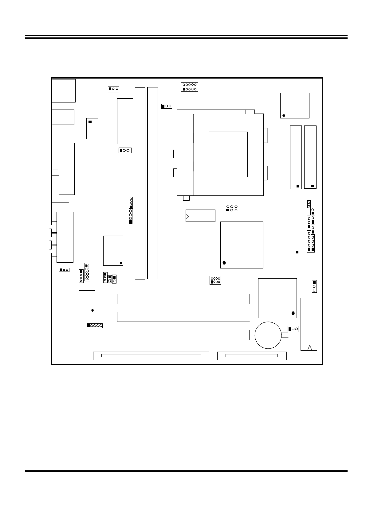
2-3-
Mainboard Layout
JP
PW1
ATX POWER CONN.
WOL
DIMM2
JP
USB
COM1
GA1
KBMS1
COM2
LINE
-OUT
JP9
CPU-FAN
64K X6
IDE2
IDE1
CPU
ZIF SO C K E T 7
DIMM1
PS-ON
SMI
32K X8
U
JP11
U12
HDLED
LINE
-I
GAME PORT
SIS530
C M I8738
SPDIFIN
JP2
JP1
U
U
JP
JP10
U17
SYSFAN
SIS559
PCI 2
PCI
IS A1
BATT
Figure 2-1
P12
BIOS
4
Page 7

2-3-
Quick Reference for Jumpers, Connectors &
Expansion Socket
Jumpers
Jumper Name Description Page
JP9 CPU Voltage Selection ON:Short , OFF:Open p. 6
JP10,JP11 CPU Bus Frequency Selection ON:Short , OFF:Open p. 6
JP12 CMOS RAM Clear 2-3 Normal , 1-2 Clear CMOS p. 8
JP3 Audio chip Enabled/Disabled 2-3 : Enabled, 1-2 : Disabled p.14
JP5 Keyboard power on function 1-2 : Disabled, 2-3 : Enabled p.15
Connectors
Connector Name Description Page
PW1 ATX Power Connector 20-Pin Block p. 9
KBMS1 PS/2 Keyboard/PS/2 Mouse 6-Pin Female p.10
USB USB Port Connector 5-Pin Connector
LPT1 Parallel Port Connector 26-Pin Female p.10
VGA1 VGA Connector 15-Pin Female p.10
GAME PORT Line IN/Line Out/MIC /Game Port Connector 15-pin Connector + 3 phone jack p.11
COM1 Serial Port COM1 10-Pin Block p.10
COM2 Serial Port COM2 10-Pin Block p.10
FDD Floppy Driver Connector 34-Pin Block p.11
IDE1 Primary IDE Connector 40-Pin Block p.11
IDE2 Secondary IDE Connector 40-Pin Block p.11
HDLED IDE activity LED 2-Pin Connector p.12
Case Connections Front Panel Connector 16-Pin Block
IR1 Infrared Module Connector 5-Pin Block p.12
CPUFAN/SYSFAN FAN Connector 3-Pin Block p.13
PS-ON ATX power button/soft power button 2-Pin Connector p.13
JP6 CD-Audio/Panasonic 4-pin Block p.14
JP7 CD-Audio/Sony 4-pin Block p.14
WOL Wake On LAN 3-pin Block P.14
JP1 AUX Connector 4-pin Block p.15
SPKIN PC Speaker In 2-pin Block p.14
SPDIFIN SPDIFIN (Sony/Philips Digital Interface) 3-pin Block p.15
SPDIFOUT SPDIFOUT (Sony/Philips Digital Interface) 2-pin Block p.15
JP2 Opticl Kit Connector 10-pin Block p.15
p.13
p.12
Expansion Slots
Socket/Slot Name Description
DIMM1,DIMM2 DIMM Module Socket 168-Pins DIMM SDRAM Module Expansion Socket
Zip Socket7 CPU Socket Socket for Central Processing Unit (CPU)
ISA1 ISA Slot 16-bits ISA Bus Expansion slots
PCI1, PCI2,PCI3 PCI Slot 32-bits PCI Local Bus Expansion slots
5
Page 8
2-3-1 Installation Steps
Before using your computer, you must follow the steps as follows:
1. Set Jumpers on the Motherboard
2. Install the CPU
3. Install DRAM Modules
4. Install Expansion card
5. Connect Cables, Wires, and Power Supply
2-3-2
Jumper Settings
CPU Voltage Selection: JP9 (2x5pin Block)
This jumper is used for adjusting CPU working voltage, for this main board design it can auto
detect the single voltage CPU or dual voltage CPU.
The table of JP9 CPU voltage selection
JP9 1-2 3-4 5-6 7-8 9-10
1.8V OFF ON OFF ON ON
2.0V OFF ON ON ON ON
2.1V ON OFF OFF OFF OFF
2.2V OFF ON OFF OFF OFF
2.3V ON ON OFF OFF OFF
2.4V OFF OFF ON OFF OFF
2.8V OFF OFF OFF ON OFF
2.9V ON OFF OFF ON OFF
3.2V OFF OFF ON ON OFF
3.3V ON OFF ON ON OFF
3.4V OFF ON ON ON OFF
3.5V
ON
ON ON ON OFF
∗ If your CPU Type is not including in above table, please refer to the CPU voltage selection on below
to choose the correct working voltage for your CPU.
JP3
2
1
1.8V
JP3
2
1
2.8V
JP3
10
2
9
1
2.0V
JP3
2
10
1
9
2.9V
JP3
2
10
9
1
10
2
9
1
2.1V
JP3
2
10
1
9
10
9
3.2V
CPU Vo ltage Select ion
2
1
JP3
JP3
2.2V
3.3V
JP3
10
2
9
1
2.3V
JP3
2
10
1
9
3.4V
JP3
2
10
9
1
10
9
2.4V
JP3
10
2
9
1
10
9
3.5V
CPU Type selection:
This mainboard designs JP10 to select the CPU external clock (Host Bus Frequency) and
JP11 to select the CPU Bus Frequency ratio, the external clock frequency multiplied by Bus
frequency ratio is the CPU frequency as the tables below:
•
Table for CPU external frequency / SDRAM Clock setting : JP10
FS0 FS1 FS2 SD CPU Bus Clock SDRAM Clock PCI Clock
ON ON ON OFF 66 MHz 66 MHz 33
ON ON ON ON 66 MHz 100 MHz 33
OFF ON ON OFF 75 MHz 75 MHz 30
ON OFF ON OFF 83 MHz 83 MHz 33
OFF ON ON ON 90 MHz 90 MHz 30
OFF OFF ON OFF 95 MHz 95 MHz 31
ON OFF ON ON 95 MHz
ON ON OFF OFF 100 MHz
63 MHz *
100 MHz *
31
33.3
6
Page 9
FS0 FS1 FS2 SD CPU Bus Clock SDRAM Clock PCI Clock
OFF OFF ON ON 100 MHz
ON ON OFF ON 100 MHz
OFF ON OFF OFF 112 MHz
OFF ON OFF ON 112 MHz
ON OFF OFF OFF 124 MHz 124 MHz 31
ON OFF OFF ON 124 MHz 82 MHz 31
OFF OFF OFF OFF 133 MHz 133 MHz 33
OFF OFF OFF ON 133 MHz 89 MHz 33
※
SDRAM Clock Asynchronous as CPU Bus frequency let user can use slow
66 MHz
75 MHz
112 MHz
74 MHz
*
*
*
*
33
30
37
37
speed SDRAM when CPU clock over 83MHz.
• Table for CPU ratio selector : JP11
CPU ratio BF0 BF1
1.5 X / 3.5 X OFF OFF OFF
2.0 X ON OFF OFF
2.5 X ON ON OFF
3.0 X OFF ON OFF
4.0 X ON OFF ON
4.5 X ON ON ON
5.0 X OFF ON ON
5.5 x OFF OFF ON
BF2
Table for CPU Type selection . S : short O : open
CPU Type
233MHz Pentium processor
with MMX technology
AMD K6-233
Cyrix 6X86 MII 300
200MHz Pentium processor
with MMX technology
AMD K6-200
Cyrix/IBM 6X86 MII 233
AMD K6/266
AMD K6-2/266
AMD K6/300 O S S S S S S 66MHz 4.5X
AMD K6-2/300 O O S S O S O 100MHz 3.0X
AMD K6-2/333 O S O O O O O 95MHz 3.5X
AMD K6-2/350 O O S S O O O 100MHz 3.5X
AMD K6-2/366 O S S S O O S 66MHz 5.5X
AMD K6-2/400 O O S S O O S 100MHz 4.0X
AMD K6-3/400 O O S S S O S 100MHz 4.0X
AMD K6-2/450 O O S S S S S 100MHz 4.5X
AMD K6-3/450 O O S S S S S 100MHz 4.5X
AMD K6-2/475 O S O O O S S 95MHz 5.0X
AMD K6-2/500, K6-3/500 O O S S O S S 100MHz 5.0X
AMD K6-2/550, K6-3/550 O O S S O O S 100MHz 5.5X
Cyrix MII-333 O S O S O S O 83MHz 3.0X
Cyrix MII-333 O S S O O O O 75MHz 3.5X
Cyrix MII-366 O O S S S S O 100MHz 2.5X
Cyrix MII-400 O S O O O S O 95MHz 3.0X
Cyrix MII-433 O O S S O S O 100MHz 3.0X
IDT Winchip-225 O S S O O S O 75MHz 3.0X
IDT Winchip2-300 O O S S S S O 100MHz 2.5X
JP10 (Bus clock) JP11 (clock ratio)
SD FS2 FS1 FS0 BF0 BF1 BF2
O S S S O O O 66MHz
O S S S
O S S S
O S O 66MHz
S O S 66MHz
Bus clock Clock ratio
3.5X
3.0X
4.0X
7
Page 10
NOTE: 1. Before installing the CPU, Please check the CPU Frequency and Clock Ratio from your
supplier.
2. For Cyrix/IBM 6X86MX series, please double check the CPU’s Frequency and Clock Ratio.
1. CMOS RAM: JP12 (Yellow color selector)
WARNING: Make sure your computer is POWER OFF when you are CLEAR CMOS.
Connect a jumper Cap over this jumper for a few seconds, will clears information stored in the
CMOS RAM Chip that input by user, such as hard disk information and passwords. After
CLEAR CMOS, you must enter the BIOS setup (by holding down <DEL> during power-up) to
re-enter BIOS information (see BIOS SETUP).
Selections JP12
Normal 2-3 (Default)
Clear CMOS 1-2 (momentarily)
CMOS RAM (Normal / Clear CMOS Data)
123
Normal
123
Clear CMOS
2-3-3 System Memory (DRAM)
This main board supports two 168-pins DIMM modules, the Max Memory Size is 512MB Because
of the VGA share memory function, the system must always occupy BANK0 (DIMM1)to booting.
DIMM 1 DIMM 2 System can be Accept or Not
168-pin DIMM
168-pin DIMM 168-pin DIMM
168-pin DIMM
168-pin DIMM 168-pin DIMM
×
× Accept
Accept
× Accept
Accept
168-pin DIMM
Not Accept
× × Not Accept
×
168-pin DIMM
Not Accept
2-4 Central Processing Unit (CPU)
The main board provides a 321-pins ZIF Socket 7. The CPU on mother board must have a fan
attached to prevent overheating.
WARNING: Without a fan, the CPU will be overheated and cause damage to both the CPU and the
motherboard.
To install a CPU, first turn off your system and remove its cover. Locate the ZIF socket and open
it by first pulling the lever sideways away from the socket then upwards to a 90-degree right angle.
Insert the CPU with the white dot as your guide. The white dot should point towards the end of
the level. The CPU has a corner pin for three of the four corners, the CPU will only fit in the one
orientation as shown as follow. With the added weight of the CPU fan, no force is required to
insert the CPU. Once completely inserted, hold down on the fan and close the socket’s lever.
8
Page 11
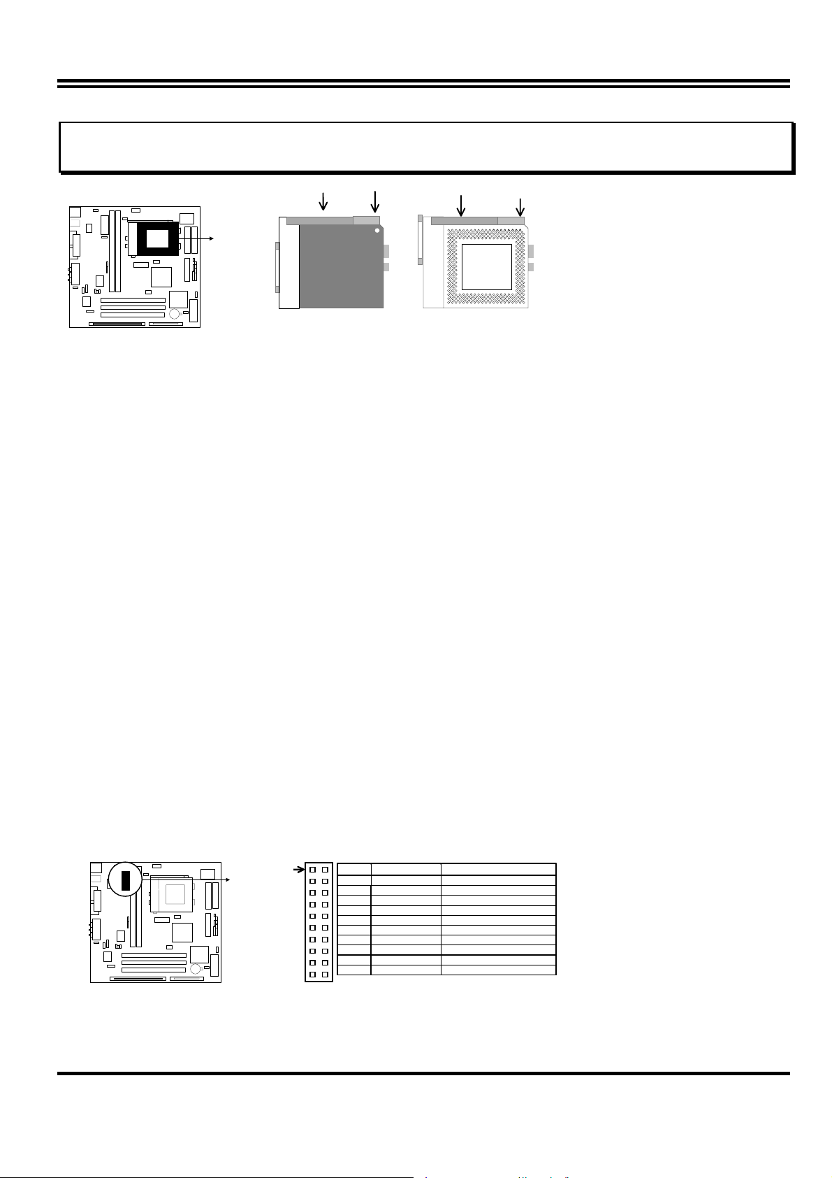
IMPORTANT: You must set jumpers JP10,JP11 “CPU Type selector” on page 6 and jumper JP9 “CPU
Voltage Selection” on page 6 depending on the CPU that you install.
White Dot
Lever
Lock
Blank
Socket 7
CPU
CPU ZIF Socket 7
Socket 7
2-5 Expansion Cards
First read your expansion card documentation on any hardware and software settings that may be
required to setup your specific card.
Installation Procedure:
1. Read the documentation for your expansion card.
2. Set any necessary jumpers on your expansion card.
3. Remove your computer’s cover.
4. Remove the bracket on the slot you intend to use.
5. Carefully align the card’s connectors and press firmly.
6. Secure the card on the slot with the screw you remove in step 4.
7. Replace the computer’s cover.
8. Setup the BIOS if necessary.
9. Install the necessary software drivers for your expansion card.
2-6 External Connectors
1. ATX Power Connector (20-pins block): PW1
ATX Power Supply connector. This is a new defined 20-pin connector that usually comes with ATX case.
The ATX Power Supply allows to use soft power on momentary switch that connect from the front panel
switch to 2-pin Power On jumper pole on the motherboard. When the power switch on the back of the ATX
power supply turned on, the full power will not come into the system board until the front panel switch is
momentarily pressed. Press this switch again will turn off the power to the system board.( * Please wait
aleast 4sec , when turn off and turn on the power .)
Pin 1
2. PS/2 Mouse & PS/2 Keyboard Connector: KBMS1
PIN ROW2 ROW1
1 3.3V 3.3V
2 -12V 3.3V
3 GND GND
4 Soft Power On 5V
5 GND GND
6 GND 5V
7 GND GND
8 -5V Power OK
9 +5V +5VSB(for Soft Logic)
10 +5V +12V
9
Page 12
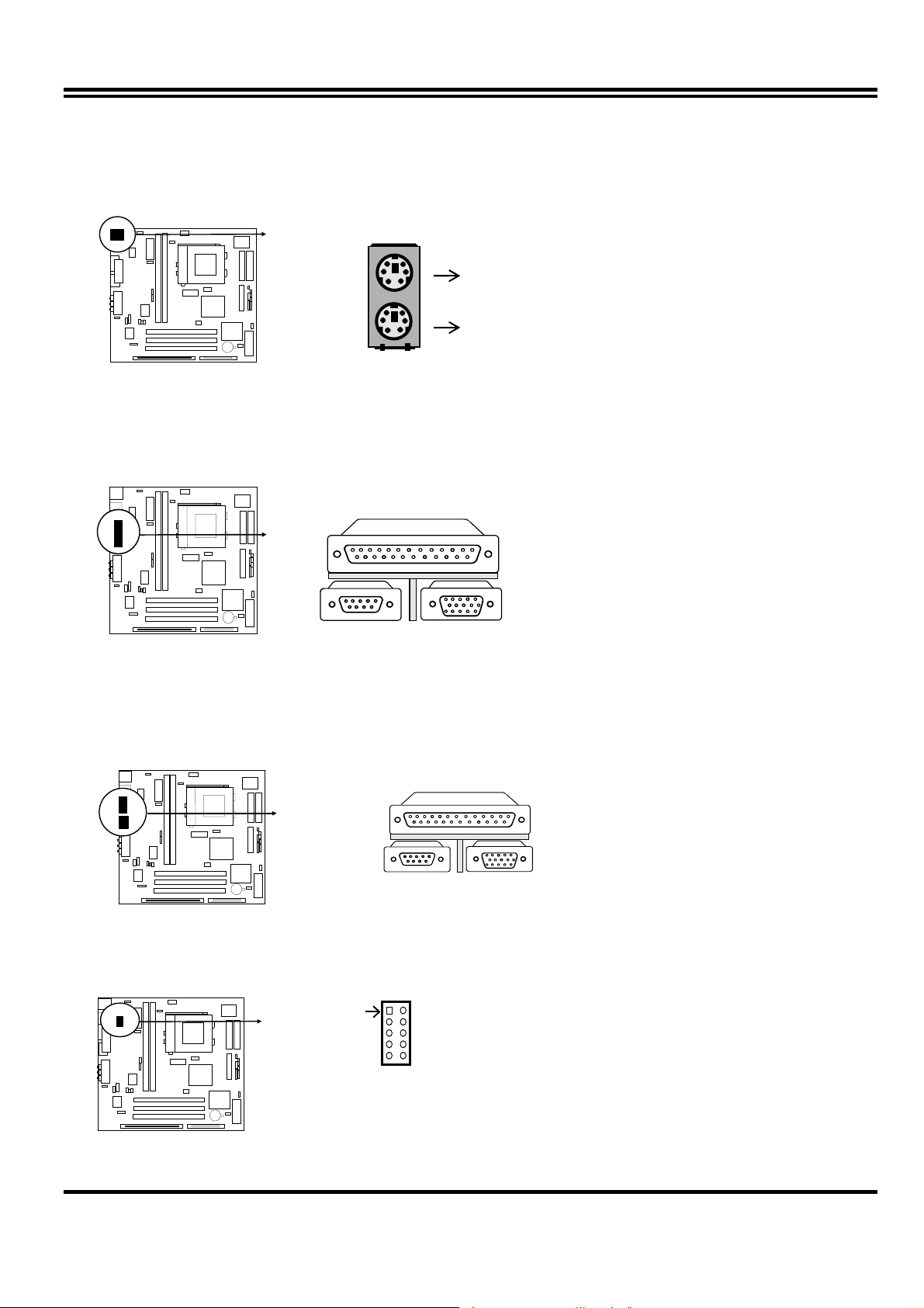
The PS/2 Keyboard is a 6-pin miniature DIN connector. It is for a standard PS/2 style
keyboard. May also be known as a 101 enhanced keyboard. The PS/2 Mouse connector is a
similar 6-pin, miniature DIN connector.
PS/2 Mouse
PS/2 Keyboard
3. Parallel Port Connector (25-pin female): LPT1
Parallel Port connector is a 25-pin D-Subminiature Receptacle connector. The On-board
Parallel Port can be disabled through the BIOS SETUP. Please refer to Chapter 3
“INTEGRATED PERIPHE RALS SETUP” section f or more detail information.
Parallel Port Connector
4. Serial Port COM1 and VGA Connector: COM1, VGA1
COM1 is the 9-pin D-Subminature mail connector. VGA1 is the 15-pin D-Subminature
Recepfacle connector.The On-board serial port can be disabled through BIOS SETUP.
Please refer to Chapter 3 “INTEGRATED PERIPHERALS SETUP“ sectio n fo r mor e detail
information.
Serial Port COM1 & VGA1 Connector
COM1 VGA 1
5. Serial Port COM2 Connector: COM2
This connector support the provided serial port ribbon cabled with mounting braket, Connect
the ribbon cable to this connector and mount the raket to the case on an open slot.
Pin 1
COM 2
Serial port COM2Connector
10
Page 13
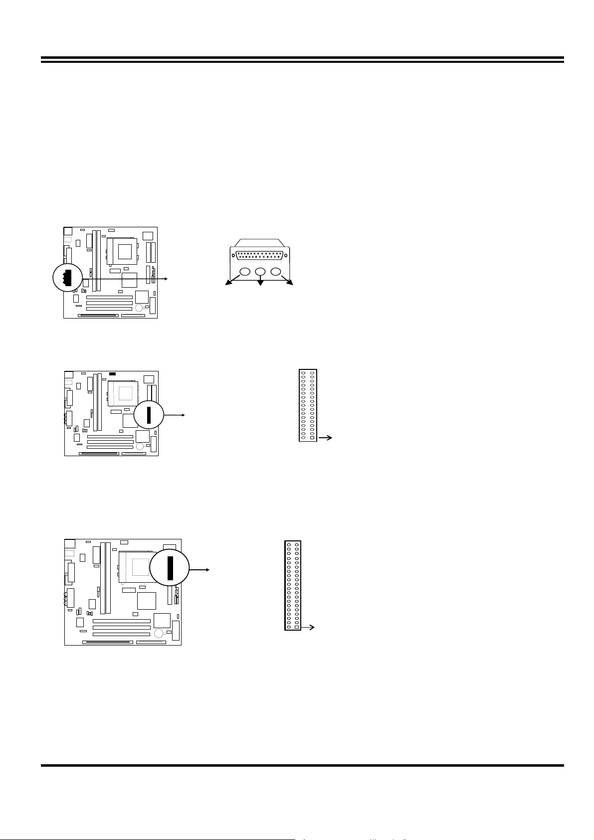
6. Audio and Game Connector : GAME PORT
This Connector are 3 phone Jack for LINE-OUT,LINE-IN,MIC and a 15-pin
D-Subminiature Receptacle Connector for joystick/MIDI Device.
Line-out : audio output to speaker
Line-in : audio input to sound chip
MIC : Microphone Connector
Game/MIDI : for joystick or MIDI Device
Game / MIDI PORT
LINE-OUT MICLINE-IN
Audio and Game Connector
7. Floppy drive Connector (34-pins block): FDD
Th is connector supports the provided floppy drive ribbon cable. After c onnecting the single plug
end to motherboard, connect the two plugs at other end to the floppy drives.
Pin 1
Floppy Drive Connector
8. Primary IDE Connector (40-pins block): IDE1
This connector supports the provided IDE hard disk ribbon cable. After connecting the single
plug end to motherboard, connect the two plugs at other end to your hard disk(s). If you install
two hard disks, you must configure the second drive to Slave mode by setting its jumpers
accordingly. Please refer to the documentation of your hard disk for the jumper settings.
Pin 1
Primary IDE C onnector
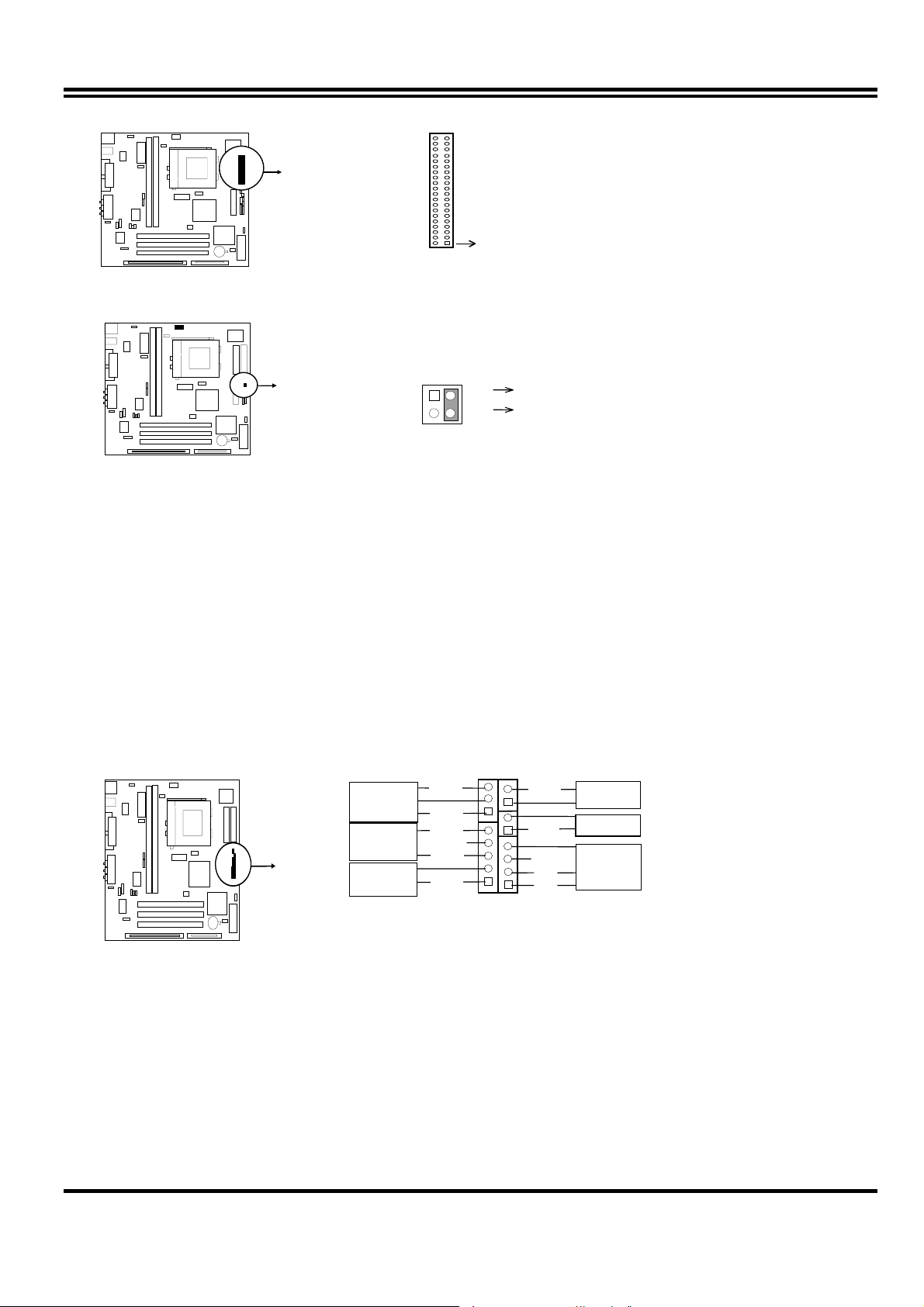
9. Secondary IDE Connector (40-pins block): IDE2
This connector connects to the next set of Master and Slave hard disks. Follow the same
procedure described for the primary IDE connector. You may also configure two hard disks to
be both Masters using one ribbon cable on the primary IDE connector and another ribbon
cable on the secondary IDE connector.
11
Page 14
VCC
Pin 1
Secondary IDE C onnector
10. IDE activity LED: HDLED
This connector connects to the hard disk activity indicator light on the case.
4
3
12
HDLED
IDE (Hard D rive) LED
-
11. Turbo LED switch: TBLED
The motherboard‘s turbo function is always on. The turbo LED will remain constantly lit while
the system power is on. You may wish to connect the Power LED from the system case to
this lead. See the figure below.
12. Reset switch lead: RESET
This 2-pin connector connects to the case-mounted reset switch for rebooting your computer
without having to turn off your power switch. This is a preferred method of rebooting in order
to prolong the life of the system‘s power supply. See the figure below.
13. Keyboard lock switch lead: KEYLOCK
This 5-pin connector connects to the case-mounted key switch for locking the keyboard for
security purposes. See the figure below.
14. Speaker connector: SPK
This 4-pins connector connects to the case-mounted speaker. See the figure below.
Turbo SW
GND
Power LED
Lock
Keyboard
NC
GND
GND
System Case Connections
GND
GND
NC
GND
VCC
Turbo LED
Reset SW
Speaker
15. IR infrared module connector: IR1
This connector supports the optional wireless transmitting and receiving infrared module.
This module mounts to small opening on system cases that support this feature you must
also configure the setting through BIOS setup. Use the four pins as shown on the Back View
and connect a ribbon cable from the module to the motherboard according to the pin definitions.
12
Page 15

GND
Infrared Module Connector
VCC
NC
IRTX
IRRX
16. USB Port connector: USB
The connectors are 4-pins connector that connect USB devices to the system board.
J2
USB Port Connector
17. CP U FAN connector: CPUFAN
CPUFAN
3
+12V
R.P.M. SENCEGND
CPU Fan Connector
18. Extra fanning system connectors: SYSFAN
SYSTEM Fan Connect or
SYSFAN
1
+
R.P.M. SENCE
3
19. Power-On button connector: PS-ON (PWR BTN 2&4)
PS-ON
2
4
GND
Push Button
Power-On button connector
13
Page 16

20. CD Audio in connector : JP6 JP7
These two connectors are design for two type of CD-ROM output cable.
JP6
1
Panasonic Compatible Sony Compatible
JP7
1
CD-ROM Audio connector
21. On board sound chip Enbled / Disabled connector : JP3
JP3
1
2
1-2 Closed: Disa bled
3
1
2
2-3 Closed: Enabled (Default)
3
22. Wake On Lan connector: WOL
1
+5VSB GND WON
23. Auxiiary lnput connector: JP1
JP1
24. PC Speaker signal lnput connesr: SPKIN
SPKIN
25.SPDIF IN (Sony / Philips Digital lnterface ) Connectors : SPDIFIN
14
Page 17

SPDIFIN
+5V
GND
SPDIFIN
26. SPDIFOUT (Sony / Philips Digital lnterface ) Connectors : SPDIFOUT
SPDIFOUT
SPDIFOUT
GND
27.Opticl kit connector :JP2
JP2
28.Keyboard Power on Selection Connector :JP5
JP5
12
12
1-2 Close : Disabled
3
2-3 Close : Enabled
3
Chapter 3
15
Page 18

AWARD BIOS SETUP
This motherboard has previously set to its best stable status. If you are not an
experienced user, please do not change the default setting. When you are encounter any
problem, please choice “LOAD STANDARD DEFAULTS” to restore best setting.
Award's ROM BIOS provides a built-in Setup program which allows user modify the basic system
configuration and hardware parameters. The modified data will be stored in a battery-backed
CMOS RAM so data will be retained even when the power is turned off. In general, the
information saved in the CMOS RAM stay unchanged unless here is configuration change in the
system, such as hard drive replacement or new equipment is installed.
It is possible that CMOS had a battery failure which cause data lose in CMOS RAM . If so , re -en ter
system configuration parameters become necessary.
To enter Setup Program
Power on the computer and press <Del> key imm ediat ely will bring you into BIOS CMOS SETUP
UTILITY.
ROM PCI/ISA BIOS (2A5IMJ1A)
CMOS SETUP UTILITY
AWARD SOFTWARE, INC.
STANDARD CMOS SETUP
BIOS FEATURES SETUP
CHIPSET FEATURES SETUP
POWER MANAGEMENT SETUP
PNP/PCI CONFIGURATION
LOAD OPTIMAL DEFAULTS
LOAD STANDARD DEFAULTS
Esc : QUIT ↑↓→← : Select Item
F10 : Save & Exit Setup (Shift) F2 : Change Color
INTEGRATED PERIPHERALS
SUPERVISOR PASSWORD
SAVE & EXIT SETUP
EXIT WITHOUT SAVING
Figure 3-1
The menu displays all the major selection items and allow user to select any one of shown item.
The selection is made by moving cursor (press any direction key) to the item and press <Enter>
key. An on_line help message is displayed at the bottom of the screen as cursor is moving to
various items which provides user better understanding of each function. When a selection is
made, the menu of selected item will appear so the user can modify associated configuration
parameters.
3-1 STANDARD CMOS SETUP
16
Page 19

Modify
Choose "STANDARD CMOS SETUP" in the CMOS SETUP UTILITY Menu (Figure 3-1). The
STANDARD CMOS SETUP allows user to configure system setting such as current date and time,
type of hard disk drive installed in the system, floppy drive type, and the type of display monitor.
Memory size is auto-detected by the BIOS and displayed for your reference. When a field is
highlighted (direction keys to move cursor and <Enter> key to select), the entries in the field will
be changed by pressing <PgDn> or <PgUp> keys or user can enter new data directly from the
keyboard.
ROM PCI/ISA BIOS (2A5IMJ1A)
STANDARD CMOS SETUP
AWARD SOFTWARE, INC.
Date (mm:dd:yy) : Fri, Dec, 18 1998
Time (hh:mm:ss) : 20 : 19 : 7
HARD DISKS TYPE SIZE CYLS HEAD PRECOMP LANDZ SECTOR MODE
Primary Master : Auto 0 0 0 0 0 0 NORMAL
Primary Slave : Auto 0 0 0 0 0 0 NORMAL
Secondary Master : Auto 0 0 0 0 0 0 NORMAL
Secondary Slave : Auto 0 0 0 0 0 0 NORMAL
Drive A : None
Drive B : None
Video : EGA/VGA
Halt On : All Errors
Base Memory : 640K
Extended Memory : 7168K
Other Memory : 384K
Total Memory : 8192K
Esc : Quit ↑↓→← : Select Item Pu/Pd/+/- :
F1 : Help (Shift)F2: Change Color
Figure 3-2
NOTE: If hard disk Primary Master/Slave and Secondary Master/Slave were used Auto, than the
hard disk size and model will be auto-detect on display during POST.
NOTE: The "Halt On:" field is to determine when to halt the system by the BIOS is error occurred
during POST.
3-2 BIOS FEATURES SETUP
17
Page 20

Select the "BIOS FEATURES SETUP" option in the CMOS SETUP UTILITY menu allows user to
change system related parameters in the displayed menu. This menu shows all of the
manufacturer's default values of this motherboard. Again, use r can move the cursor by pressin g
direction keys and <PgDn> of <PgUp> keys to modify the parameters. Pressing [F1] key to
display help message of the selected item.
This setup program also provide 2 convinent ways to load the default parameter data from BIOS
[F6] or CMOS [F7] area if shown data is corrupted. This provides the system a capability to
recover from any possible error.
ROM PCI/ISA BIOS (2A5IMJ1A)
BIOS FEATURES SETUP
AWARD SOFTWARE, INC.
Virus Warning : Disabled
CPU Internal Cache : Enabled
External Cache : Enabled
Quick Power On Self Test : Enabled
Boot Sequence : A,C,SCSI
Swap Floppy Drive : Disabled
Boot Up Floppy Seek : Enabled
Boot Up NumLock Status : On
Memory Pariy Check : Enabled
Typematic Rate Setting : Disabled
Typematic Rate (Chars/Sec) : 6
Typematic Delay (Msec) : 250
Security Option : Setup
PCI/VGA Palette Snoop : Disabled
OS Select For DRAM > 64MB : Non-OS2
Report No FDD For WIN 95 : No
Figure 3-3
Video BIOS Shadow : Enabled
C8000-CBFFF Shadow : Disabled
CC000-CFFFF Shadow : Disabled
D0000-D3FFF Shadow : Disabled
D4000-D7FFF Shadow : Disabled
D8000-DBFFF Shadow : Disabled
DC000-DFFFF Shadow : Disabled
Esc: Quit ↑↓→← : Select Item
F1 : Help Pu/Pd/+/-:Modify
F5 : Old Values (Shift)F2 : Color
F6 : Load BIOS Defaults
F7 : Load Setup Defaults
Note: The Security Option contains "setu p" and "system". The "setup" indicates that the passw ord
setting is for CMOS only while the "system" indicates the password setting is for both CMOS
and system boot up procedure.
3-3 CHIPSET FEATURES SETUP
This section describes features of the SiS 530 AGP set . lf your system contains a different
18
Page 21

chipset, this section will bear little resemblance to what you see on your screen.
ADVANCED OPTIONS. The parameters in this screen are for system designers, service
personnel, and technically competent users only. Do not reset these values unless you
understand the consequences of your changes.
ROM PCI/ISA BIOS (2A5IMJ1A)
CHIPSET FEATURES SETUP
AWARD SOFTWARE ,INC
Auto Configuration : Enabled
Refresh Rate Control : 15.6us
Ref/Act Command Delay : 6T
Refresh Queue Depth : 12
RAS Precharge Time : 3T
RAS to CAS Delay : 3T
ISA Bus clock Frequency : PCICLK/4
Starting Point of Paging : 1T
NA# Enable : Enabled
L2 Cache Burst RD Cycle : Delay 1T
Asyn/Sync Mode CPU/DRAM : Asynchronous
SDRAM CAS Latency : 3T
SDRAM WR Retire Rate : X-1-1-1
DRAM Opt RAS Precharge : Enabled
PCI Peer Concurrency : Enabled
Read Prefetch Memory : Enabled
Assert TRDY After Prefet : 2 QWs
CPU to PCI Burst Mem. WR : Enabled
CPU to PCI Post Write : Enabled
AGP Aperture Size : 64MB
Figure 3-4
System BIOS Cacheable : Enabled
Video BIOS Cacheable : Enabled
Memory Hole at 15M-16M : Disabled
DRAM Controller 1 T WR : Enabled
DRAM Controller 1 T RD : Enabled
PCI Post Write Buffer : Enabled
PCI Delayed Transaction : Disabled
Auto Detect DIMM/PCI Clk : Enabled
Spread Spectrum : Disabled
Esc: Quit ↑↓→←: Select Item
F1 : Help Pu/Pd/+/-:Modify
F5 : Old Values (Shift)F2 : Color
F6 : Load BIOS Defaults
F7 : Load Setup Defaults
This section allows you to configure the system based on the specific features of the installed
chipset. This chipset manages bus speeds and access to system memory resources, such as
DRAM and the external cache. It also coordinates communications between the conventional ISA
bus and the PCI bus. It must be stated that these items should never need to be altered. The
default settings have been chosen because they provide the best operating conditions for your
system. The only time you might consider making any changes would be if you discovered that
data was being lost while using your system.
3-4 POWER MANAGEMENT SETUP
19
Page 22

The Power Management Setup allows you to configure you system to most effectively save
energy while operating in a manner consistent with your own style of computer use.
ROM PCI/ISA BIOS (2A5IMJ1A)
POWER MANAGEMENT SETUP
AWARD SOFTWARE, INC.
ACPI function : Enabled
Power Management : User Define
Video Off Option : Susp Stby-> Off
Video Off Mothod : V/H SYNC+Blank
Switch Function : Break/Wake
Doze Speed (div by) : 2/8
Stdby Speed(div by) : 1/8
MODEM Use IRQ : 3
Hot Key Fumction As : Power OFF
** PM Monitor **
HDD Off After : Disable
Doze Mode : Disable
Standby Mode : Disable
Suspend Mode : Disable
** PM Events **
HDD Ports Actovoty : Enabled
COM Ports Actovoty : Enabled
LPT Ports Actovoty : Enabled
VGA Activity : Enabled
IRQ [3-7 , 9-15], NMI : Enabled
IRQ 8 Bredk Suspend : Disabled
Power Button Over Ride : Instant OFF
Ring Power Up Control : Enabled
KB Power ON Password : Enter
Power Up by Alarm : Disabled
Esc: Quit ↑↓→←: Select Item
F1 : Help Pu/Pd/+/-: Modify
F5 : Old Values (Shift)F2 : Color
F6 : Load BIOS Defaults
F7 : Load Setup Defaults
Figure 3-5
• Video Off Method : This determines the manner in which the monitor is blanked.
V/H
SYNC+Blank
This selection will cause the system to turn off
the vertical and horizontal synchronization ports
and write blanks to the video buffer.
Blank Screen This option only writes blanks to the video buffer.
DPMS Select this option if your monitor supports the
Display Power Management Signaling (DPMS)
standard of the Video Electronics Standards to
select video power management values.
• Switch Function : You can choose whether or not to permit your system to enter
complete Suspend mode. Suspend mode offers greater power savings, with a
correspondingly longer awakening period.
• Doze Speed (div by): Sets the CPU's speed during Doze mode. The speed is reduced to a
fraction of the CPU's normal speed. The divisors range from 1 to 8
The choice: 1~8.
• Stdby Speed (div by) :Select a divisor to reduce the CPU speed during Standby mode to a
fraction of the full CPU speed. The speed is reduced to a fraction of the CPU's normal speed.
The divisors range from 1 to 8-0.
The choice: 1~8
• MODEM Use IRQ: Name the interrupt request (IRQ) line assigned to the modem (if any) on
your system. Activity of the selected IRQ always awakens the system.
The choice: 3, 4, 5, 7, 9, 10, 11, NA.
• Hot Key Function As : Select Enabled if your system has a hot key for soft power off.
The choice: Power off, Suspend ,Disabled.
20
Page 23

• PM Timers : The following four modes are Green PC power saving functions which are only
user configurable when User Defined Power Management has been selected.
See above for available selections.
• HDD Off After : By default, this item is Disabled, meaning that no matter the mode the rest of
the system, the hard drive will remain ready. Otherwise, you have a range of choices from 1 to
15 minutes or Suspend. This means that you can elect to have your hard disk drive be turned
off after a selected number of minutes or when the rest of the system goes into a Suspend
mode.
• Doze Mode : When enabled and after the set time of system inactivity, the CPU clock will run
at slower speed while all other devices still operate at full speed.
• Standby Mode : When enabled and after the set time of system inactivity, the fixed disk drive
and the video would be shut off while all other devices still operate at full speed.
• Suspend Mode : When enabled and after the set time of system inactivity, all devices except
the CPU will be shut off.
• PM Events : You may disable activity monitoring of some common I/O events and
interrupt requests so they do not wake up the system. The default wake-up event is keyboard
activity.
• HDD Ports Activity : When set to On (default), any event occurring at a HDD (serial) port will
awaken a system which has been powered down.
• COM Ports Activity : When set to On (def ault), any event occurring at a hard or
floppy drive port will awaken a system which has been powered down.
• LPT Ports Activity : When set to On (defa ult), any event occurring at a LP T (printer) port will
awaken a system which has been powered down.
• VGA Activity : When set to On (default), any event occurring at VGA will awaken a
system which has been powered down.
The following is a list of IRQ’s, Interrupt ReQuests, which can be exempted much as the COM
ports and LPT ports above can. When an I/O device wants to gain the attention of the
operating system, it signals this by causing an IRQ to occur. When the operating system is
ready to respond to the request, it interrupts itself and performs the service.
As above, the choices are On and Off.
When set On, activity will neither prevent the system from going into a power management
mode nor awaken it.
• IRQ [ 3-7, 9-15], NMI
• IRQ 8 Break Suspend : You can Enable or Disable monitoring of IRQ8 (the Real
Time Clock) so it does not awaken the system from Suspend mode.
• Power Button Over Ride : You could press the power button for more than 4
seconds forces the system to enter the Soft-Off state when the system has “hung.”
The choice: Instant-Off, Delay 4 Sec.
• Ring Power Up Control : When you select Enabled, a signal from ring returns the
system to Full On state.
• GPIO5 Power Up Control : When you select Enabled, a signal from General
Purpose Input 05 returns the system to Full On state.
The choice: Enabled, Disabled.
• KB Power ON Password : When you set a password for keyboard, The password
you set the keyboard that returns the system to Full On state.
• Power Up by Alarm : When you select Enabled, the following fields appear. They
let you set the alarm that returns the system to Full On state.
The choice: Enabled, Disabled.
21
Page 24

3-4-1 The Description of the Power Management
• Power Management mode selection:
User Define: This category allows you to select the type (or degree) of power
saving and is directly related to the following modes:
1. HDD Power Down
2. Doze Mode
3. Standby Mode
4. Suspend Mode
There are four selections for Power Management, three of which have fixed mode settings.
Disable (default) No power management. Disables all four modes
Min. Power Saving Minimum power management. Doze Mode = 1 hr.
Standby Mode = 1 hr., Suspend Mode = 1 hr., and
HDD Power Down = 15 min.
Max. Power Saving Maximum power management -- ONLY AVAILABLE
FOR SL CPU’S. Doze Mode = 1 min., Standby Mode
= 1 min., Suspend Mode = 1 min., and HDD Power
Down = 1 min.
User Defined Allows you to set each mode individually. When not
disabled, each of the ranges are from 1 min. to 1 hr.
except for HDD Power Down which ranges from 1 min.
to 15 min. and disable.
PM Control APM:
When enabled, an Advanced Power Management device will be activated to enhance the Max.
Power Saving mode and stop the CPU internal clock. If Advance Power Management (APM) is
installed on your system, selecting Yes gives better power savings.
If the Max. Power Saving is not enabled, this will be preset to No.
MODEM Use IRQ:
This determines the IRQ in which the MODEM can use.
The choices: 3, 4, 5, 7, 9, 10, 11, NA.
Video Off Option:
When enabled, this feature allows the VGA adapter to operate in a power saving mode.
Always On Monitor will remain on during power saving
modes.
Suspend --> Off Monitor blanked when the systems enters the
Suspend mode.
Susp,Stby --> Off Monitor blanked when the system enters either
Suspend or Standby modes.
All Modes --> Off Monitor blanked when the system enters any
power saving mode.
Video Off Method:
This determines the manner in which the monitor is blanked.
V/H SYNC+Blank This selection will cause the system to tu rn off the
vertical and horizontal synchronization ports and
write blanks to the video buffer.
Blank Screen This option only writes blanks to the video buffer.
DPMS Select this option if your monitor supports the
Display Power Management Signaling (DPMS)
22
Page 25

standard of the Video Electronics Standards to
select video power management values.
• PM Monitors:
The following four modes are Green PC power saving functions which are only user configurable
when User Defined Power Management has been selected. See above for available selections.
HDD Power Dow n:
When enabled and after the set time of system inactivity, the hard disk drive will be powered
down while all other devices remain active.
Doze Mode:
When enabled and after the set tim e of system inactivity, the CPU clock will run at slower speed
while all other devices still operate at full speed.
Standby Mode:
When enabled and after the set time of system inactivity, the fixed disk drive and the video would
be shut off while all other devices still operate at full speed.
Suspend Mode:
When enabled and after the set tim e of system inactivity, all devices except the CPU will be shut
off.
• Standby Events:
When Enabled, an event occurring on each device listed below restarts the global time
for Standby mode.
Primary HDD
Floppy Disk
Serial Port
Keyboard
Parallel Port
• External Switch:
This wake-up optional is special for M/B manufacturers’ design.
Power Button:
This item allows you to select the function of power button.
The choice: Disabled, Green Mode, Power Off.
DOCK I/O SMI:
This item allows you to enable or disable the function of DOCK I/O SMI.
The choice: Enabled, Disabled.
3-4-2 Description of the Green Functions
This motherboard supports HDD Power Down, Doze and standby power saving functions when
Intel Pentium processor CPU is installed. The detail description of these functions are provided
as following:
HDD Standby Mode
When system stop reading or writing HDD, the timer starts to count. The system will cut off the
HDD power when timer ran out of time. The system will not resume operation until either a read
from or a write to HDD command is executed again.
Doze Mode
The system hardware will drop down CPU clock from normal working speed when Doze mode
timeout occurred.
Standby Mode
When the system standby mode timer ran out, it will enter the standby mode and retain CPU at
slow working speed. The screen will be blanked out.
Suspend Mode
23
Page 26

When the system suspend timer time out, the system will enter the suspend mode and the
chipset will stop CPU clock immediately. The power consunption in Suspend Mode is lower than
in standby mode. The screen is also blanked out.
PM Events:
AWARD BIOS defines 15 PM Events in the power management mode (Doze, standby &
suspend). The user can initial any PM Events to be "Enable" or "Disable". When the system
detects all of the enabled events do not have any activity, it will start the system Doze timer first if
the "Power Management" isn't "Disabled". Once the system Doze timer timed out, it will process
doze power saving procedure by starting the system standby timer. W hen the standby timer ran
out and all of the "Enabled" events remains silent, the system will enter the standby mode. By
now, the system will not only process the standby power saving procedures but also start the
system suspend timer. When the suspend timer time out, all of the CPU clock will be stopped by
dropping system clock down to zero and remains this way until any one of the "Enabled" event
occurred.
• Power Button Over Ride: User can choice power off mothod, by instant off or 4 sec off.
• Ring Power Up Control: When setting this item Enabled, and press the power button to
power off. After Rin g in the system will auto power on.
• Pow er Up by Alarm: Default value is Disabled , when choice enabled you can setting Date of
Month, Time Alarm to setup the time and the date to power on the computer.
3-5 PNP/PCI CONFIGURATION SETUP
This section describes configuring the PCI bus system. PCI, or Personal Computer Interconnect,
is a system which allows I/O devices to operate at speeds nearing the speed the CPU itself uses
when communicating with its own special components. This section covers some very technical
items and it is strongly recommended that only experienced users should make any changes to
the default settings.
ROM PCI/ISA BIOS (2A5IMJ1A)
PNP/PCI CONFIGURATION SETUP
AWARD SOFTWARE, INC.
Resources Controlled By : Manual
Reset Configuration Data: Disabled
IRQ-3 assigned to : PCI/ISA PnP
IRQ-4 assigned to : PCI/ISA PnP
IRQ-5 assigned to : PCI/ISA PnP
IRQ-7 assigned to : Legacy ISA
IRQ-9 assigned to : PCI/ISA PnP
IRQ-10 assigned to : PCI/ISA PnP
IRQ-11 assigned to : PCI/ISA PnP
IRQ-12 assigned to : PCI/ISA PnP
IRQ-14 assigned to : Legacy ISA
IRQ-15 assigned to : Legacy ISA
DMA-0 assigned to : PCI/ISA PnP
DMA-1 assigned to : PCI/ISA PnP
DMA-3 assigned to : PCI/ISA PnP
DMA-5 assigned to : PCI/ISA PnP
DMA-6 assigned to : PCI/ISA PnP
DMA-7 assigned to : PCI/ISA PnP
PCI IRQ Actived By : Level
Esc: Quit ↑↓→←: Select Item
F1 : Help Pu/Pd/+/-:Modify
F5 : Old Values (Shift)F2 : Color
F6 : Load BIOS Defaults
F7 : Load Setup Defaults
Figure 3-6
24
Page 27

3-6 LOAD OPTIMAL DEFAULTS
The "LOAD OPTIMAL DEFAULTS" function loads the system default data directly from ROM and
initialize associated hardware properly. This function will be necessary only when the system
CMOS data is corrupted.
ROM PCI/ISA BIOS (2A5IMJ1A)
CMOS SETUP UTILITY
AWARD SOFTWARE, INC.
STANDARD CMOS SETUP
BIOS FEATURES SETUP
CHIPSET FEATURES SETUP
POWER MANAGEMENT
PNP/PCI CONFIGURA
LOAD OPTIMAL DEFAULTS
LOAD STANDARD DEFAULTS
Esc : QUIT ↑↓→← : Select Item
F10 : Save & Exit Setup (Shift) F2 : Change Color
Load optimal Default (Y/N)? Y
Time, Date, Hard Disk Type...
INTEGRATED PERIPHERALS
SUPERVISOR PASSWORD
USER PASSWORD
ECTION
FORMAT
SAVE & EXIT SETUP
EXIT WITHOUT SAVING
Figure 3-7
3-7 LOAD STANDARD DEFAULTS
The "LOAD STANDARD DEFAULTS" function loads the system default data directly from ROM
and initialize associated hardware properly. This function will be necessary only when the system
CMOS data is corrupted.
ROM PCI/ISA BIOS (2A5IMJ1A)
CMOS SETUP UTILITY
AWARD SOFTWARE, INC.
STANDARD CMOS SETUP
BIOS FEATURES SETUP
CHIPSET FEATURES SETUP
POWER MANAGEMENT SETUP
PNP/PCI CONFIGURA
INTEGRATED PERIPHERALS
SUPERVISOR PASSWORD
USER PASSWORD
IDE HDD AUTO DETECTION
ORMAT
Load STANDARD Default (Y/N)? Y
LOAD OPTIMAL DEFAUL
LOAD STANDARD DEFAULTS
Esc : QUIT ↑↓→← : Select Item
F10 : Save & Exit Setup (Shift) F2 : Change Color
Time, Date, Hard Disk Type...
UP
EXIT WITHOUT SAVING
Figure 3-8
25
Page 28

3-8 INTEGRATED PERIPHERALS SETUP
The “INTEGRATED PERIPHERALS SETUP” mainly deals with I/O function. This function
will be necessary only when the system I/O malfunctioned or the system is unable to
detects your CD-ROM or hard disk.
ROM PCI/ISA BIOS (2A5IMJ1A)
INTEGRATED PERIPHERALS
AWARD SOFTWARE, INC.
Internal PCI : Both
IDE Primary Master PIO : Auto
IDE Primary Slave PIO : Auto
IDE Secondary Master PIO : Auto
IDE Secondary Slave PIO : Auto
Primary Master UltraDMA : Auto
Primary Slave UtraDMA : Auto
Secondary Master UtraDMA : Auto
Secondary Slave UtraDMA : Auto
IDE Burst Mode : Enabled
IDE Data Port Post Write : Disabled
IDE HDD Block Modeller : Enabled
Onboard FDC Controller : Enabled
Onboard Seriel Port 1 : 3F8/IRQ4
Onboard Seriel Port 2 : 2F8/IRQ3
IR Address Select : Disabled
Onboard Parallel Port : 378/IRQ7
Power ON Function : SPP
USB Controller : Enabled
USB Keyboard Support : Disabled
Init Display Frist : PCI slot
VGA Shared Memory Size : 2MB
VGA Memory Clock(MHz) : 66
Current CPU Temperature : 40°C
Current CPUFAN Speed : 0
Current SYSFAN Speed : 0
12 Volt: 12 V 5 Volt : 5.01V
Vcc3 : 3.01V Vcore : 2.1V
Esc: Quit ↑↓→←: Select Item
F1 : Help Pu/Pd/+/-:Modify
F5 : Old Values (Shift)F2 : Color
F6 : Load BIOS Defaults
F7 : Load Setup Defaults
Figure 3-9
3-9 SUPERVISOR/USER PASSWO RD
This item lets you configure the system so that a password is required each time the system
boots or an attempt is made to enter the Setup program (Refer to Figure 3-3 for the details).
Supervisor Password allows you to change all CMOS settings but the User Password setting
doesn’t have this function. The way to set up the passwords for both Supervisor and User are as
follow:
1. Choose either Supervisor Password or User Password in the Main Menu and press <Enter>.
The following message appears:
“Enter Password:”
2. The first time you run this option, enter your password up to only 8 characters and press
<Enter>. The screen does not display the entered characters. For no password just press
<Enter>.
3. After you enter the password, the following message appears prompting you to confirm the
password:
“Confirm Password:”
4. Enter exact the same password you just typed again to confirm the password and press
<Enter>.
5. Move the cursor to Save & Exit Setup to save the password.
6. I f you need to delete the password you entered before, choose the Supe rvisor P asswor d and
Press <Enter>. It will delete the password that you bad before.
7. Move the cursor to Save & Exit Setup to save the option you did, otherwise the old password
will still be there when you turn on your machine next time.
3-10 SAVE & EXIT SETUP
26
Page 29

The "SAVE & EXIT SETUP" option will bring you back to boot up procedure with all the changes
you just made which are recorded in the CMOS RAM.
3-11 EXIT WITHOUT SAVING
The "EXIT WIT HOUT SAVING" option will bring you back to normal boot up procedure without
saving any data into CMOS RAM. All of the old data in the CMOS will not be destroyed.
Chapter 4
Software lnstalled
27
Page 30

4-1 On Board VGA Driver Quick Installation
WINDOWS 95/98/98SE Display Driver Quick Installation
Step 1. Before Install the driver please view the “readme” file.
Step 2. Run “X:\SiS530\VGA\WIN9X\SETUP.EXE”
(if your CD-ROM is X drive)
Step 3. Follow the setup procedure install your VGA Driver.
WINDOWS NT4.0 Display Driver Quick Installation
Step 1. Boot form Windows NT4.0, Double-click "My computer" icon, "Control panel" icon,
"Display" icon
Step 2. When the "Display properties" window appear, choose "setting" tab, select "Display
type"
Step 3. When the "Display type" window appear, Select "Change"
Step 4. When the "Change Display" window appear, select "Have Disk", Change the directory
path from "A:\" to " X:\SiS530\VGA\WinNT40 ", select "OK". (if your CD-ROM is D driver)
Step 5. When the "Display type" window appear again, select "CLOSE".
Step 6. When the "Display properties" window appear again, select "CLOSE"
Step 7. Restart Windows NT40
Step 8. When the "Display properties" window appear, setup your resolution, select "test", select
"OK", you will be finished your installation
4-2 PC HEALTH MONITOR Driver Quick Installation
§
In Windows 95/ Windows 98/Windows 98 SE
step1: Run X:\ SiS 530 \ HEALTH \ SETUP.EXE.
step2: Selet “Next” to complete install driver.
step3: The program will automatic install driver to system if users have
question in system Hardware Monitor Setting, please read “HELP”
Section in program.
4-3 Sound Driver & Audio Rack Installation:
Special Features for CMI8738 audio chip
PCI Plug and Play (PnP) bus interface, 32 bit PCI bus master.
Full duplex playback and recording, built-in 16 bits CODEC.
HRTF 3D positional audio, supports both Direct Sound 3D® & A3D® interfaces, supports earphones,
two and four channel speakers mode.
Support Windows 3.1 / 95 / 98 / 98 SE and Windows NT 4.0.
Built-in 32 OHM Earphone buffer and 3D surround.
MPU-401 Game/Midi port and legacy audio SB16 support.
Downloadable Wave Table Synthesizer, supports Direct Music®.
• Digital Audio (SPDIF IN/OUT)
Up to 24 bit stereo 44KHz sampling rate voice playback/recording.
Full duplex playback and recording, 120dB audio quality measured.
Auto detectable SPDIF/IN signal level from 0.5V to 5V.
28
Page 31

• Stereo Mixer and FM Music Synthesizer
Stereo analog mixing from CD-Audio, Line-in
Stereo digital mixing from Voice, FM/Wave-table, Digital CD-Audio
Mono mixing from MIC and software adjustable volume
OPL3 FM synthesizer (4 operators)
Up to 15 melody sounds and 5 rhythm sounds (20 voices)
• Game and Midi Interface
Fully compatible with MPU-401 Midi UART and Sound Blaster Midi
mode/ Standard IBM PC joystick/game port (dual channels)
DOS Installation
Before beginning the installation, please make sure that your hard disk has sufficient space(min. 4MB).
Insert the Driver CD into the CD-ROM Drive.
1. Change directory to PCI audio DOS drivers folder (ex. X:\CMI8738\DOSDRV) at DOS prompt, and type:
INSTALL [Enter]
2. Type DOS utilities path which you want to install.
3. Program will expand the file to the path which you've specified.
4. Install program will add initial drivers into AUTOEXEC.BAT file.
Win95/98/98SE Installation
We recommend that you install Microsoft Windows before you install this PCI sound card, and you not
install any other sound card device drivers in your current system.
1. Turn on the computer , and enter the Microsoft Windows 95/98
2. Before install sound card driver please double-click “My Computer” icon, “Control Panel” icon ,
“System” icon, and choose “Device Manager” item.
3. Check “Other Device” item ,if there have “PCI Multimedia Audio Device”, please remove it first ,and
Restart System again.
4. You will see a windows prompt like this:
“New Hardware Found PCI Multimedia Audio Device Windows has found new hardware and is
installing the software for it” , then the dialog box shown Click “Next” button to go on.
5. Click “Other Locations” button to specify drivers path:
“ X:\CMI8738\Win9X\DRV”
6. Select “OK” to finish install.
7. Now, system is installing device drivers automatically. After a while, the system will finish the installation
includes the following device drivers.
CMI8738/C3DX PCI Audio Device
CMI8738/C3DX PCI Audio Joystick Device
CMI8738/C3DX PCI Audio Legacy Device
DOS mode MPU-401 Emulator
8. Install Application Software : Click “start” key
9. Select “Run”
10. Key in the drive and path for Windows application installation program, for example,
in Win95 “X:\CMI8738\Win9X\APP\Win95\SETUP.EXE”
29
Page 32

in Win98 “X:\CMI8738\Win9X\APP\Win98\SETUP.EXE”
11. Click “OK” to start the installation procedure, and follow the on-screen instructions to finish the
installation. When all the application softwares have been installed, please shut down Windows 95/98
system, and reboot your system.
Win95/98/98SE Un-Installation
If you install Win95/98 and a sound card at the same time, you might experience some technical
difficulties(the device might not function properly). It is suggested that you proceed with the un-install
procedure:
1. Click "start" button.
2. Select "run" item.
3. Find UINSTDRV.EXE in driver disk under Win95/98 drivers folder.
4. Run it.
5. Follow the on-screen instructions to re-install the hardware.
If you want to completely remove the drivers, you can also run the un-install procedure as described
previously. Remove the sound card from the slot, and then reboot the system.
Windows NT 4.0 Installation
We recommend that you install Windows NT 4.0 before you install this PCI audio card, and you
not install any other sound card device drivers in your current system.
1. Click “Start” button, move the highlight bar to “Setting” item, and select the “Control Panel”.
2. Double-click “Multimedia” icon.
3. Select “Devices” page, and press “Add” button.
4. Select “Unlisted or Updated Driver” item in “List of Drivers”.
5. Specify the drive and the path where NT drivers are in (such as X:\CMI8738\NT40\DRV).
6. Select “C-Media CM8738” item and press “OK” button.
7. Select proper I/O value.
8. Press “OK” button.
9. Restart the system when being asked.
10. Now, you have already installed the PCI Audio Adapter under Microsoft Windows NT 4.0
successfully. if you want to install the Windows applications, continue the following steps:
11. Click “start” key.
12. Select “Run” item.
13. Key in drive and path for Windows NT application installation program, for example,
“X:\CMI8738\NT40\APP\SETUP.EXE”
14. Click “OK” to start the installation procedure, and follow the on-screen instructions to finish the
installation. When all of application softwares have been installed, shut down the Windows
NT system, and then reboot your system.
Windows Appc. (The Audio Rack)
Introduction
30
Page 33

By means of a user-friendly interface(as easy as operating your home stereo system), this PCI
audio rack provides you with the control over your PC’s audio functions, including the advantage
of four speakers mode enable/ disable, and perfect digital sound ( SPDIF ) input / output control.
This Audio Rack consists of several major components:
Control Center: Controls the display of the PCI Audio Rack’s components.
MIDI Player: Plays MIDI music files, and allows you to create your personal song playlists, and
play the song files.
Wave Player: Records and plays digital audio (wave) files. Allows you to create wave file
playlists, and playback the wave files.
CD Player: Plays standard audio CDs. Allows you to create your favorite song playlists.
System Mixer: Controls the volume level of your audio inputs and outputs.
Showing or Hiding Audio Rack Components
To remove or add a component from the display, click on the component's button on the Control
Center’s Button Bar or toggle it off.
MIDI Player, Wave Player, and CD Player
CD Player (above, similar to Wave Player and MIDI Player)
Sel (or Trk) fielX: If you have multiple selections in your playlist, this shows the number of the
current selection or CD track.
31
Page 34

Current File or Track: The name of the current MIDI file, wave audio file, or CD track.
Total Length fielX: displays the total length of files or tracks in minutes and seconds.
Current Time fielX: displays the current time of files or tracks in minutes and seconds when
playback or recording.
Please refer to the help screen for more detail button function descriptions. (click on help
“?” button on the player)
System Mixer
System Mixer allows you to control all the audio output and input levels.
System Mixer displays the volume controls which your audio drivers make available. The names
for these controls may vary.
Mixer panel while the four speakers mode is enabled.
Mixer panel while the four speakers mode is disabled.
Volume Control: Clicking on this button shows and allows you to use the output level controls.
Recording Control: Clicking on this button shows and allows you use the input level controls.
Input and Output Level Sliders and Buttons: For each input or output signal type, the control
slider controls the loudness whereas the horizontal slider controls the balance between the two
speakers. The mute button temporarily stops input or output without changing slider positions.
Control types and names might vary. The common types are listed below:
• Vol: The master control for all outputs. The strength of an output signal is determined by both
the Vol slider and the slider for the individual output. To affect all outputs, move the Vol slider.
To change the output of an individual output type, move its slider.
• Line-in/Rear: Controls the audio hardware's Line In or Line Out levels. Line levels might be for
an externally attached cassette player, for instance, while the four speakers mode is enabled,
this control becomes the Rear speaker volume control.
• Mic: Controls the microphone input level.
• Wave: Controls wave (voice) playback or the recording levels.
• FM: Controls the FM music playback or the recording level.
• Aux-in: Controls the Aux-in music play or the recording level.
• PC-SPK: Controls the external PC speaker input level.
• CX: Controls the CD drive output level, for CD drives configured to play their audio output
through the PC’s audio hardware.
• 4SPK: Turn on or turn off the Rear speakers effect.
32
Page 35

• SurrounX: Turn on or turn off the 3D surround sound effect.
• SPDIF-in: Turn on or turn off the SPDIF digital signal input.
Mute Buttons: Toggle between muting and enabling the signal. A button with a lit LED is enabled,
and when it is not lit, it means it is mute. Several output signals can usually be enabled at once.
The 4 Speakers System
This Audio Adapter provides 2 wave channels(front/rear), known as the 4 speakers system.
When games or application programs via DirectSound® 3D or A3D® interface locate the sound
sources to the listener's back, the two rear speakers will work to enhance the rear audio
positional effect, so as to complement the insufficiency of using only two front speakers to
emulate the
audio effect. The following is the hardware installation and the software setups:
1. The speaker installation.
Connect the front pair speakers to the Line-out jack of the audio adapter, and then connect rear
pair speakers to Line-in/Rear jack of the audio adapter. The original Line-in can be moved to
Aux-in.
2. The positions of the speakers
Put your speakers the way the following picture suggests, so as to avail yourself to the best
audio result.
3. The mixer setup
There is a 4 speakers option in the volume control of the mixer, and when you enable this option,
it means the rear speakers are connected to Line-in/Rear jack. When Line-in/Rear jack is
connected to other external Line-in sources, please DO NOT enable this option in order to avoid
hardware conflicts. Regarding rear speaker option, you can turn on or turn off the output of the
back speakers, and adjust the volume, to have the rear/front speakers have the same volume.
4. The demo
Execute the "Helicopter" demo within the C3D HRTF Positional Audio Demos of this audio
adapter. When the helicopter flies behind you, the rear speakers will work.
Optical Kid for 531CF SPDIF/OUT (Optional)
The Optical Kid includes:
z Optical Module
z Optical Cable
33
Page 36

An example of optical kit is used to connect the sound card and the MD.
The application program setup(please install CMI8738 application program first)
When the connection is done, please go to the Start menu and select PCI Audio
Applications\Audio Environment Setting
34
Page 37

When all the procedures have been completed, there will be an infrared signal coming from the
SPDIF/OUT of the optical fiber of the sound card.
35
Page 38

Please note that signal beam may cause severe damage to the eyes. For your safety,
please point the output end to a piece of white paper to check if thebeam is in function.
Please connect the output signal to the MD input, then play the music via the MP3 player:
36
Page 39

Please note that in playback, if there is no gap longer than three seconds betw een each track, the
MD can not recognize the tracks and will record all of them into one. It is recommended that you
set the gap time to 3~5 seconds to meet all type of MD requirements.
37
Page 40

About Recording 24bit Audio Setting
24-bit audio can only be applied to SPDIF IN/OUT mode; it does not apply to other modes
such as the four channels or the analog. No sound will be heard while in playback, yet it
can be recrded.
38
Page 41

The un-selected area will be gray out.
The un-selected area will be gray out.
39
Page 42

The un-selected area will be gray out.
You can double-click this circuit icon to have the following setting box. By means of this setting box,
you can also complete the above-mentioned setting procedures.
531CF SPDIF/IN
An example of Portable CD Player(Output) t o 531CF(Optical Input)Setup
40
Page 43

When the connection is done, please go to the Start menu and select PCI Audio
Applications\Audio Environment Setting
41
Page 44

3.Loopback(bypass)mode setup
CD ROM (Digital Output) to 531CF (SPDIF/IN)Setup
42
Page 45

When the connection is done, please go to the Start menu and select PCI Audio
Applications\Audio Environment Setting
Please follow these setting procedures.
43
Page 46

Now you can insert the CD into the CD ROM drive, then activate C-MEDIA CD player and
push the ”play” button to do the recording job.
Please note that you have to set the MD in the simultaneous-recording mode.
44
 Loading...