

Page 1
Page 2
1
Table of contents
Ⅰ. CAUTION 2
Ⅱ. INTRODUCTION OF PRODUCTS 4
Ⅲ. DIRECTIONS FOR USE 12
Ⅳ. FUNCTIONAL SETTING BY THE KEYBOARD 26
Ⅴ. OSD MESSAGE DISCRIPTION 29
Ⅵ. TROUBLE SHOOTING 31
Ⅶ. DIMENSION 32
Ⅷ. ASSEMBLY 34
Ⅸ. SPECIFICATION 38
Page 3
2
Ⅰ.
CAUTION
Thank you for purchasing our product. Please operate the product after being fully aware of
the manual. Pease contact us if you have any queries.
Note the following matters before the installation of the product.
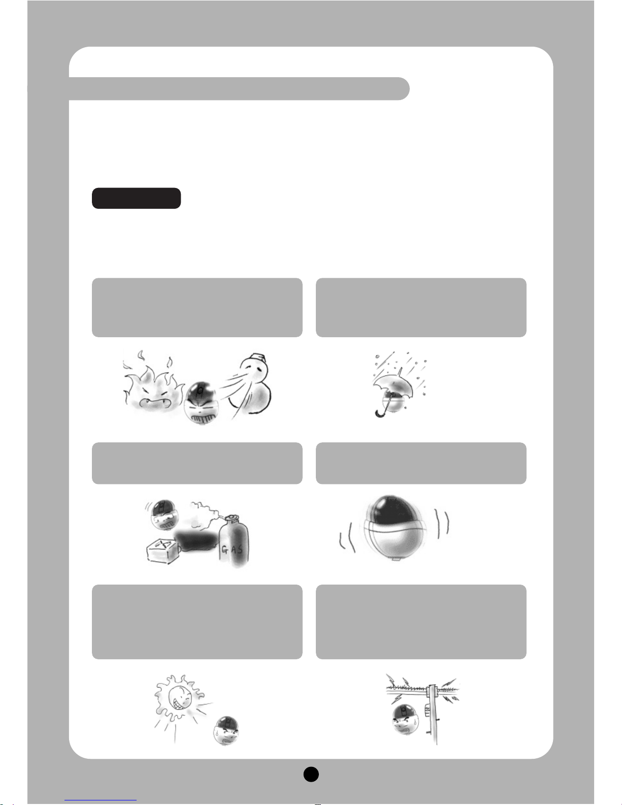
Avoid the following places for the installation.
Precaution
A high/low temperature: Using indoorcameras in the places of +50℃~ -10℃can
cause troubles and lower its capacity.
Snow, rain and wet: Humidity or water
and any liquid inside-camera can cause
troubles.
Oil, gas: Oil and gas can damage the
camera as they go through the cameras.
Vibration, shock: They bring on problems
or errors of the camera.
Direct light, exposure to the air: In the
case of that sets indoor- cameras outside
where the weather is changeable, it can
cause problems.
Closing to High frequency and electric
power lines: Setting the camera up
around electromagnetic units or power
supplier can cause problems.
Page 4
3
① Must use AC24V power source, current intensity must be less than 1.5A and must use a
double winding transformer
② Never extend the power line from adaptor to camera.
③ Please use more thick cable than 18AWG(1.0mm), if you want to extend the power line.
④ You must use one adaptor per one camera that is being provided.
⑤ Use extra power supplier, If you want to supply many piece of cameras.
- Disassembling the unit or putting alien substances such as a metal can make the camera
defective.
- Make sure of power switch-off before the installation.
: Ensure power switch-off and check the voltage the camera before the installation.
- Do not give the unit a shock and an operation.
: Giving a strong shock or an excessive power on the button, terminal can cause
problem.
Caution
Caution in Use
Page 5
4
Ⅱ.
INTRODUCTION OF PRODUCT
1. DESCRIPTION AND FEATURES
- Description
This camera has been designed elegantly for buildings, department stores that need to be in
harmony with the interior as a high speed dome camera, including various observation functions.
- Features
High Zoom Rate
Built-in High Zoom (27x, 33x, 37x)
Rate Camera with 12x Digital Zoom
A low light function
Surveillance with optimum picture is
possible owing to digital-slow-shutter
function.
Digital-slow-shutter function is
improving the CCD sensitivity by
electrically lengthening exposure time
so that it should be under surveillance
on the condition of 0.00005Lux in B/W
Wide Dynamic Range
Wide-dynamic-range function is
possible to look at object clearer in
back light condition. (Only Optical 37x
Speed Dome Camera)
Digital Noise Reduction
DNR significantly reduces the amount
of low luminance noise.
Digital Image Stabilize
There is some tremble as zoom
magnification is high, the function can
compensate the tremble.
HLC/User BLC Function
The HLC settings selectively
eliminates high lights in a limited.
Auto Tilt Function
The unit can track the moving object
automatically until 180° in vertical by
using controller.
16 Privacy Masking Zones
For the privacy, it can be programmed
for masking zone up to 16 locations
on the OSD menu screen.
250 Preset positions
A maximum of 250 preset positions
can be programmed. The preset
function enables to set where you
want on monitor at any time.
Various auto-surveillance functions
Swing(2), Group(12 Presets), Tour(12
Groups), Spiral, Trace
Smart pan/tilt function
Pan and tilt speed compensation
function in proportion to depth of
zoom.
Page 6
5
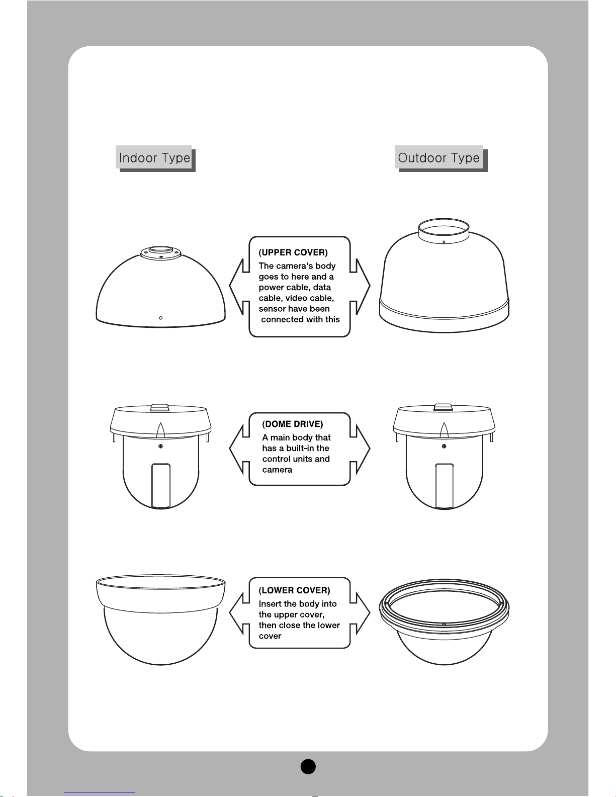
2. INSTALLATION AND CONNECTION
1) Name and function of each part
Page 7
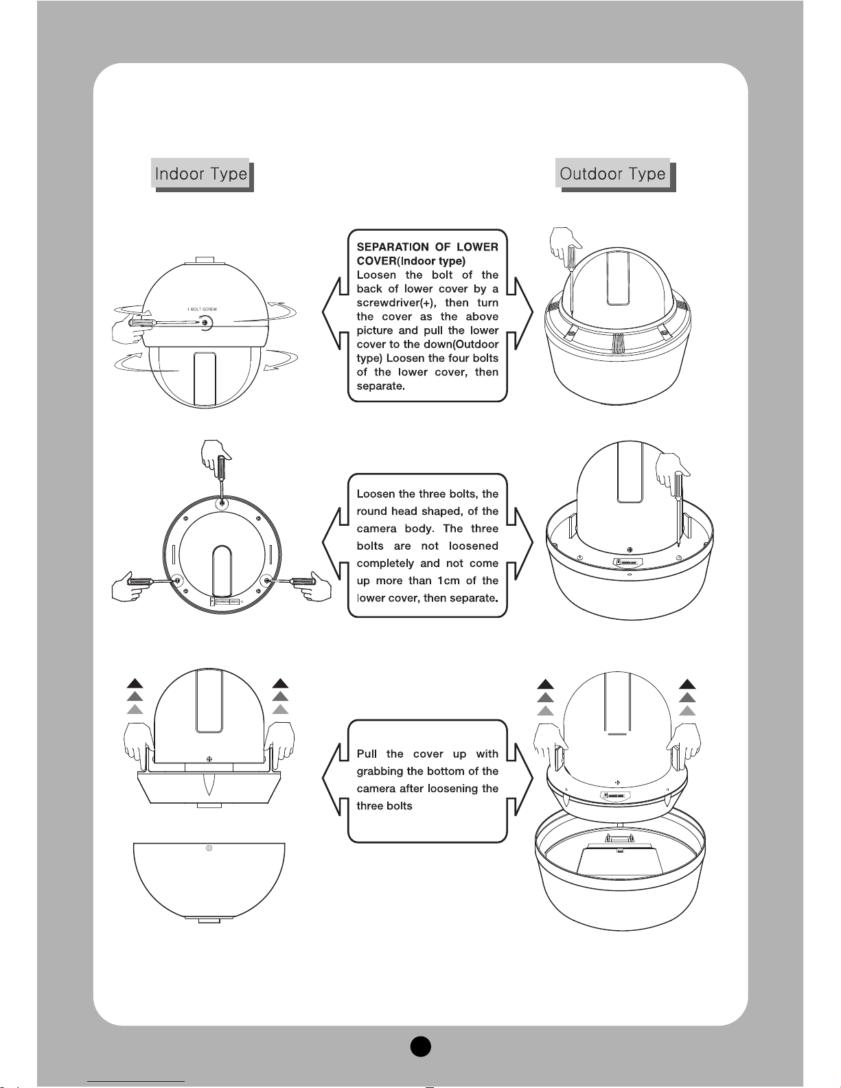
6
2) Installation
Page 8
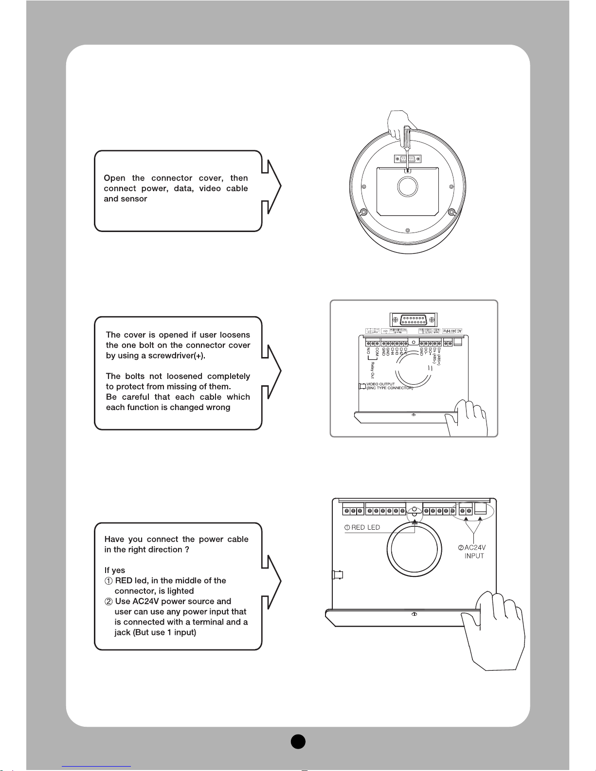
7
Page 9
8
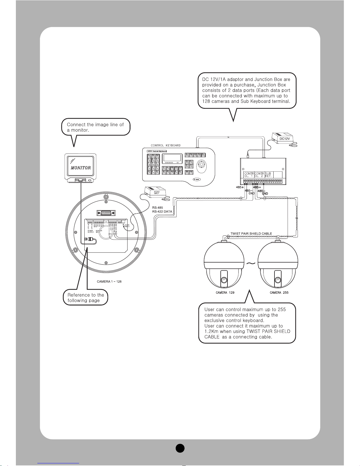
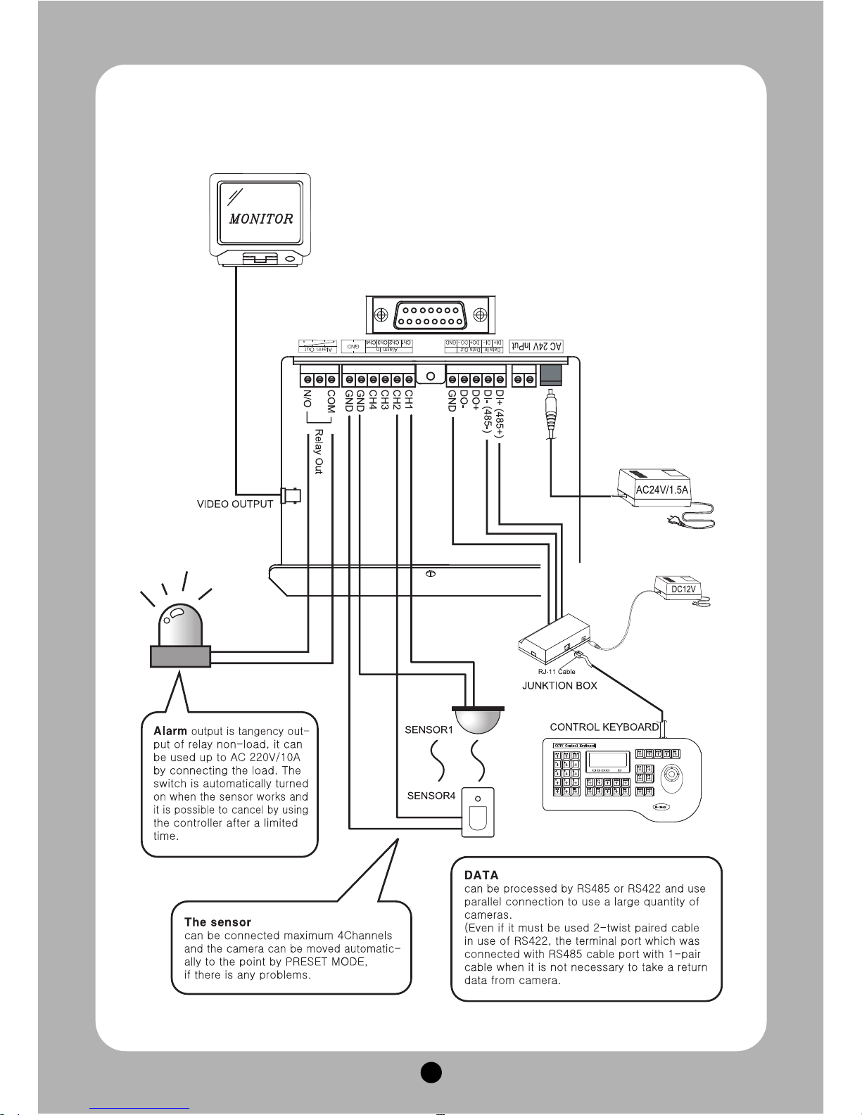
3) How to connect equipments
Page 10
9
Page 11
10
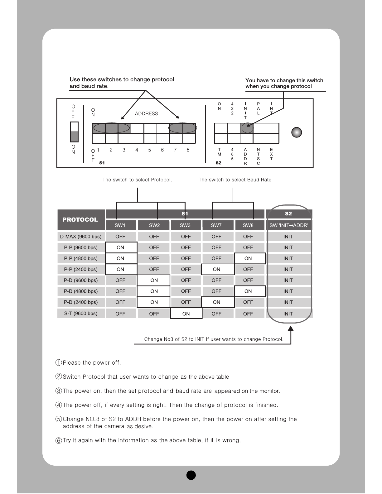
4) HOW TO SET PROTOCOL
Page 12
11
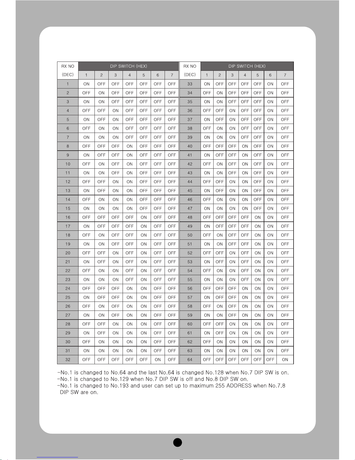
5) SETTING ADDRESS OF DIP SWITCHES
Page 13
12
Ⅲ.
DIRECTIONS FOR USE
●●
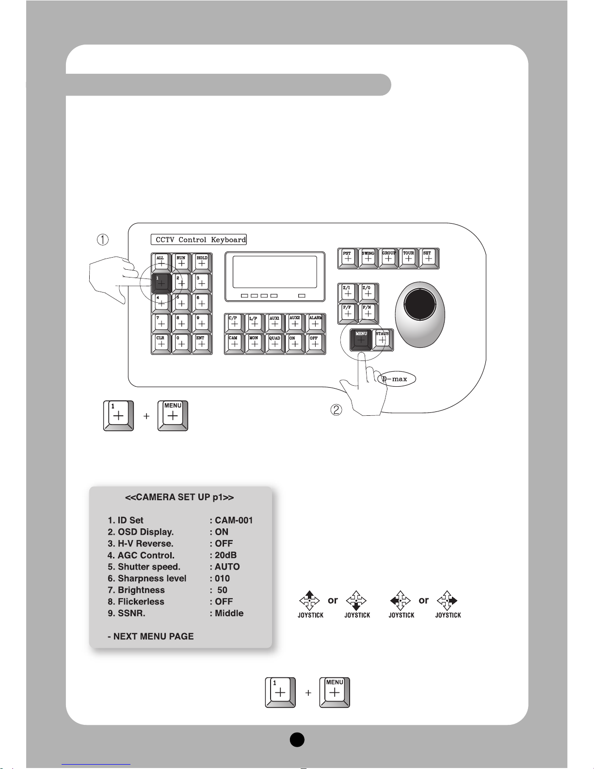
OSD (ON SCREEN DISPLAY) menu control
It is the function to call up the Menu
※
User can not only set Preset, Group, Tour, Swing, Trace functions of the camera up by
the menu, but also set them up by shortening keys.
●●
Accessing OSD menu
●●
The menu is displayed on the screen with the key tone when user presses No.1 and
menu key.
●●
Cancellation of OSD menu
●●
OSD Menu Control Up, Down, Right and
Left moving of Cursor like under pictures
Page 14
13
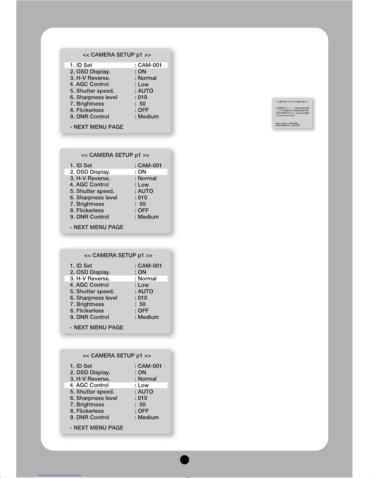
1. ID SET.
This function is to set camera ID up to 16 letters on the
monitor. User can choose letters that they want, if user
control a joystick up / down / right / left, and user can
reselect the previous letters, if user presses Z/I, Z/O or
turn the head of the joystick to right/left
2. OSD DISPLAY.
Set up whether user sets ID and STATUS to display
on the screen in normal operating.
•ID + Status : ‘ID’ and ‘Status’ displayed on the
screen
•ID only : Only ‘ID’ displayed on the screen
•Status only : Only ‘Status’ displayed on the screen
•All off : Nothing displayed on the screen
3. H-V REVERSE
Set up H-V reverse mode.
•Normal
•H-REV : You can flip the picture horizontally on the
screen.
•V-REV : You can flip the picture vertically on the
screen.
•HV-REV : You can flip the picture horizontally and
vertically on the screen.
4. AGC CONTROL
AGC(Automatic Gain Control)- It adjusts the amount of
video amplification to maintain a full 1-volt peak-topeak video signal output automatically.
▶ Low, Medium, Max
Page 15
14
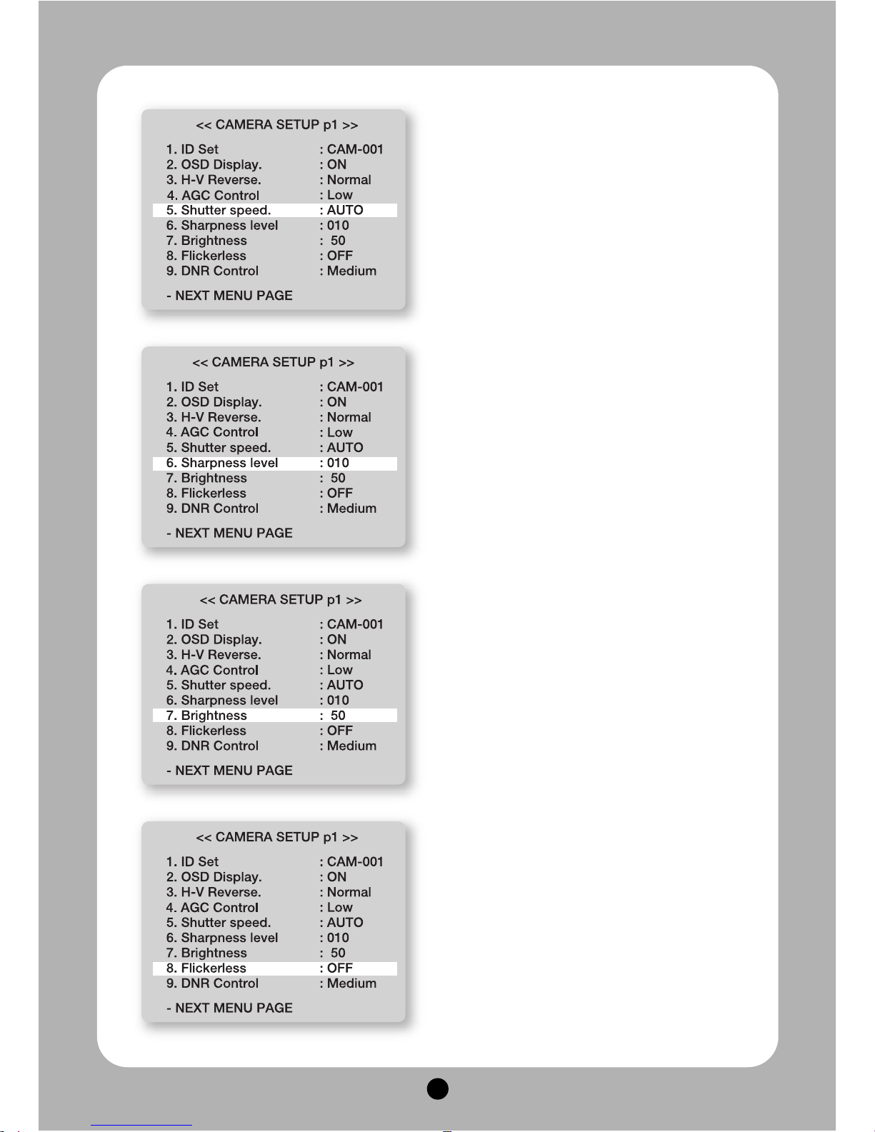
5. SHUTTER SPEED
As a setting shutter speed mode, it can be distinguished
a fast moving subject easily by means of shutter speed
up.
※ Attention-The illumination of the camera decreases
if shutter speed is up.
※ The state of first default is ‘AUTO’.
※ It can be worked in the state of Flickerless ‘off’
▶ Range : Auto, 1/125, 1/150, 1/200, --- 1/10000
6. SHARPNESS LEVEL
Compensation of the shape of a subject
▶ Range : 0 ~ 14, Default : 10
7. BRIGHTNESS
Control brightness of a screen.
The screen gets dark because an iris is closed as the
numerical value is low, whereas the screen gets
bright because an iris is opened as the numerical
value is high.
▶ Range: 0~99, Default : 50
8. FLICKERLESS
Tremble on the screen is removed in the state of
FLICKERLESS ‘ON’, the shutter speed, at the same
time, is fixed in 1/120sec in NTSC and in 1/100sec in
PAL.
Page 16
15
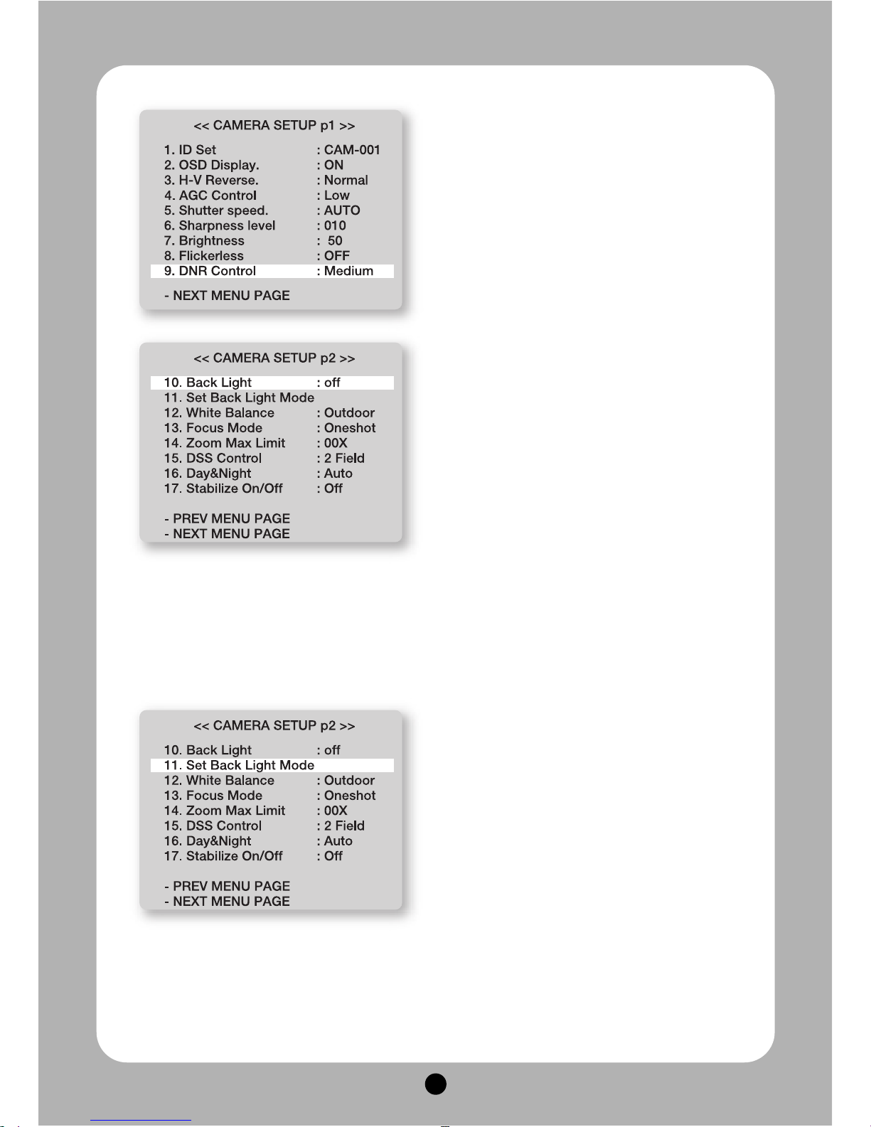
9. DNR CONTROL
It can remarkably reduce noise of minimum
illumination by super noise removable technique and
also file size becomes smaller while DVR is being
recorded by the effective reduction of noise.
▶ Off, Low, Medium, Max
10. BACK LIGHT
This camera is designed so that it delivers a distinctive
subject and background at the same time, even when
the subject is in backlight, unlike conventional
cameras, by adopting a proprietary DSP chip.
Please select a suitable mode below them (The Set
Back Light Mode will be automatically changed by the
selection)
▶ Off, WDR MODE, HLC MODE, BLC MODE
- WDR : When there are both bright and dark
areas at the same time, this mode makes both
11. SET BACK LIGHT MODE
▶ WDR MODE(Only37xspeeddomecamera)
- Limit : Adjust the WDR Sensitivity by selecting
Medium or Max
- Leve l: Adjust the WDR Brightness by controlling
1~100.
▶ HLC(High Light Compensation)MODE
- Limit: Adjust the HLC Sensitivity by selecting Low
or Max
- Level: Adjust the WDR Brightness by controlling
1~10.
- This Function operate in nighttime only.
▶ BLC MODE : Select BLC mode or BLC Set area
areas distinctive (this function only has 37x speed dome camera)
- BLC : Enables a user to directly select a desired area from a picture, and to view the area more clearly.
- HLC(High Light Compensation) : If there is a high light installed in dark environment such as an
apartment parking garage or gas station entrance, removing the high light makes it possible to view car
license plates efficiently
- OFF : Deactivates the BACKLIGHT function.
mode by using the joystick.
- BLC Level : Adjust the BLC Sensitivity by selecting Low or Max
- BLC Set AREA (Press F/F) : Set BLC area location and size
- Select F/F button, and set the BLC area by using the joystick, and set are size by using Z/I, Z/O buttons.
(The monitor shows as Exit BLC set(Press F/N)
After complete all setup, press F/N button, and then move to RETURN MENU PAGE. It is automatically
saved.
Page 17
16
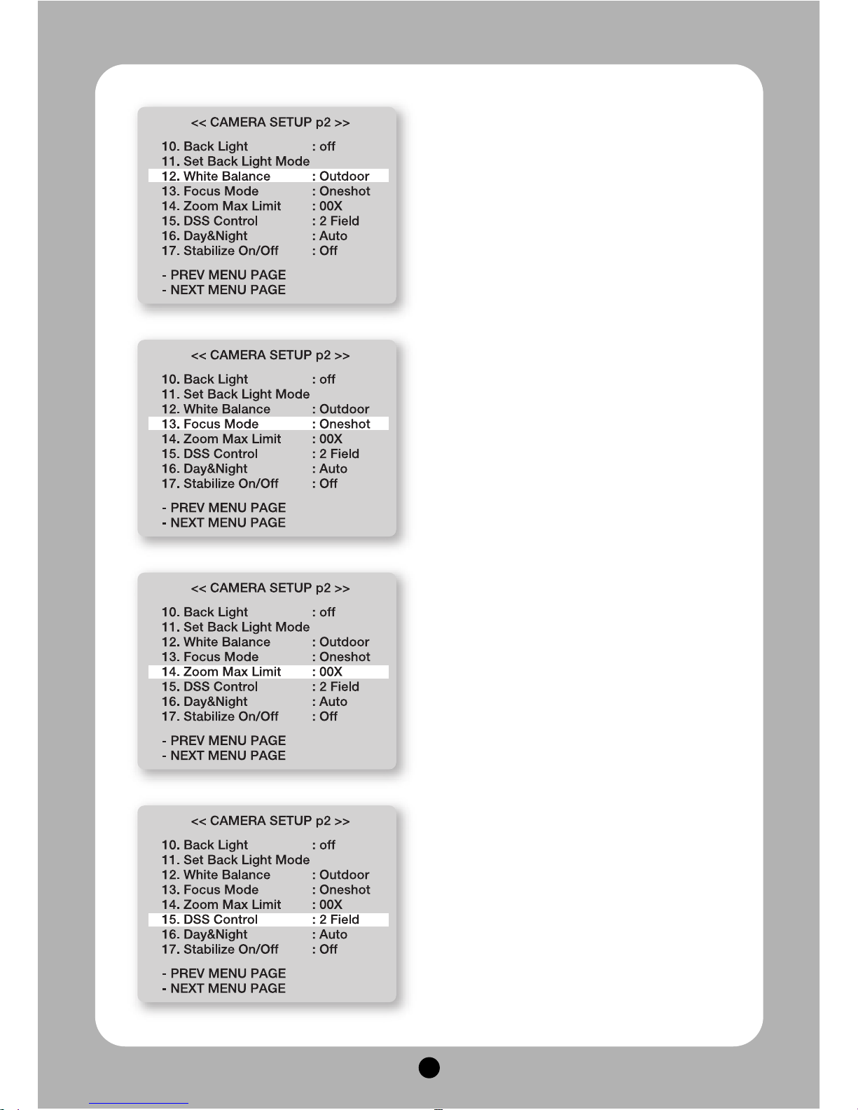
12. WHITE BALANCE
It prevents from that white color is changed as
illumination, user can set it up in 2 ways.
▶ Indoor, Outdoor
13. FOCUS MODE
Change Focus Mode to hand-worked or auto.
▶ OneShot : Auto Focusing mode works during non-
working after zoom is worked.
▶ Auto : It adjusts the focus automatically as it
monitors the screen.
▶ Manual : User can control the focus by hand-
worked.
14. ZOOM MAX Limit
It is used when user corrects and limits the
extensional range of the focus as a function to set the
maximum value of zoom.
▶ Off, 27x zoom : 54X ~ 444X
27x zoom : 54X ~ 444X
33x zoom : 66X ~ 396X
37x zoom : 74X ~ 444X
15. DSS CONTROL
An object becomes clear as the field value gets
higher in illumination, whereas a moving object
becomes dim.
▶ Range : Off, 2 ~ 256 fields
Page 18
17
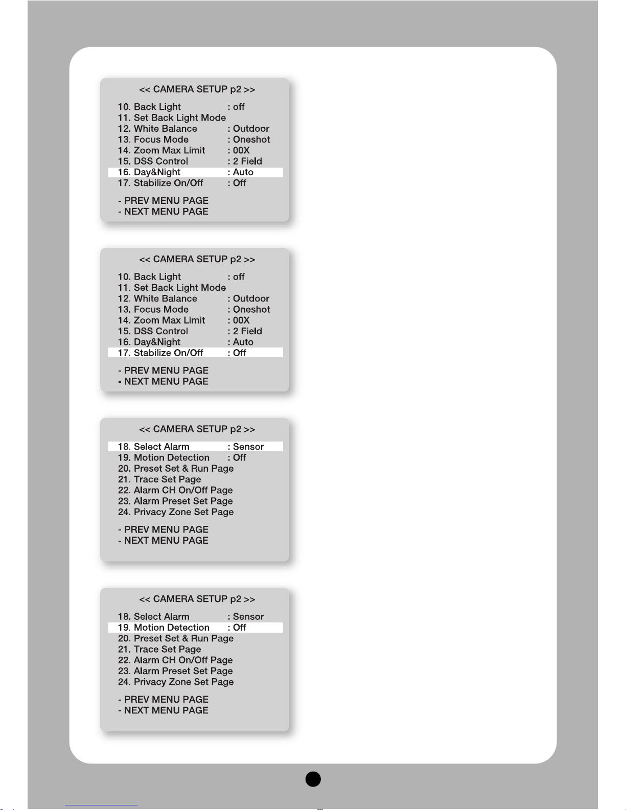
16. DAY& NIGHTF
The function is used to distinguish an object clearly in
the dark condition.
▶ Auto-Low : This mode is worked automatically
according to sensitivity, if the sensitivity is low
▶ Auto-Hi : This mode is worked automatically
according to sensitivity, if the sensitivity is high.
▶ On : Change into DAY & NIGHTY mode by hand-
worked
▶ Off : Set DAY & NIGHTY mode ‘off’
17. STABILIZE On/Off
There is some tremble as zoom magnification is high,
the function can compensate the tremble.
▶ On / Off
18. SELECT ALARM
Select alarm detection.
▶ Sensor / Motion
19. MOTION DETECTION
Set Motion ‘On’ after move the camera where user
wants.
It displays the message ‘Motion Detected’ on the
screen when the moving of an object is sensed on
the same screen.
Page 19
18
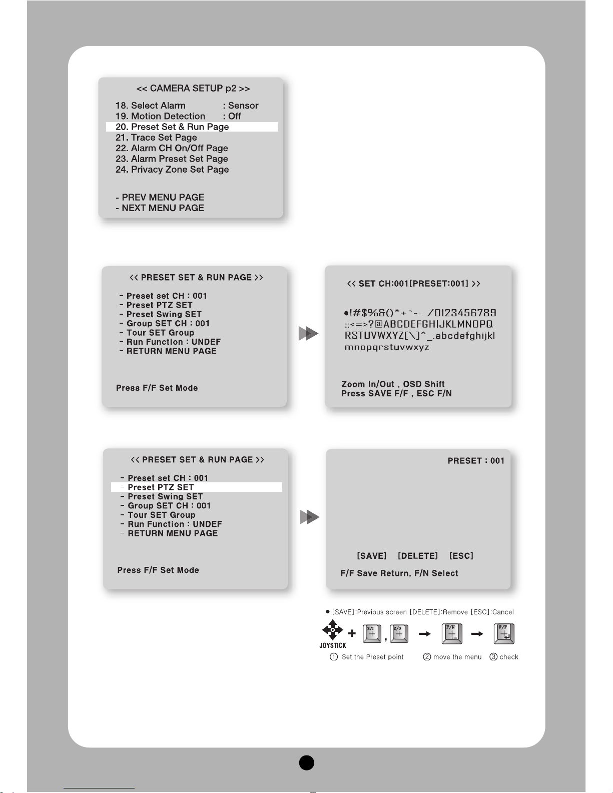
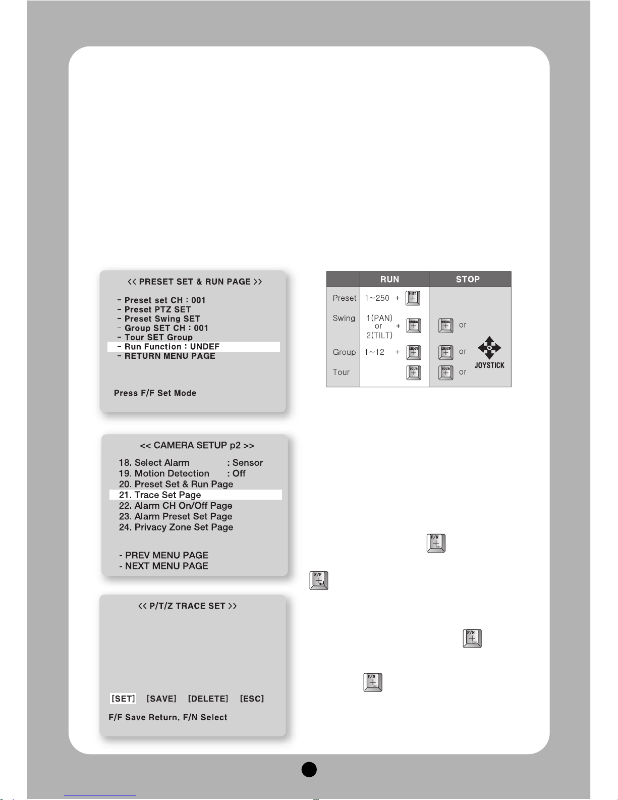
20. PRESET SET & RUN PAGE
It is a function to set and operate Preset, Group, Tour.
User can see the screen when moves the joystick to
Right/Left after fixing the cursor on the menu.
<<PRESET SETUP PAGE>>
① Preset set CH : User can set Preset No. and title
on this menu.
- Preset No. set : Set it by moving the joystick to
Right/Left
- Preset title set : User can see the menu “SET
ID” when press F/F key after setting Preset No
② Preset PTZ set : Set the position of Preset Select
the main menu with the joystick, then press F/F key
for next page.
Select [SAVE] with F/N key after setting the Preset
point by using the joystick and zoom in/out, then
the data is saved if user presses F/F key, then it is
moved to the previous screen automatically from
the menu
※ Repeat the same way after changing the number
of Preset, if user set another Preset
Page 20
19
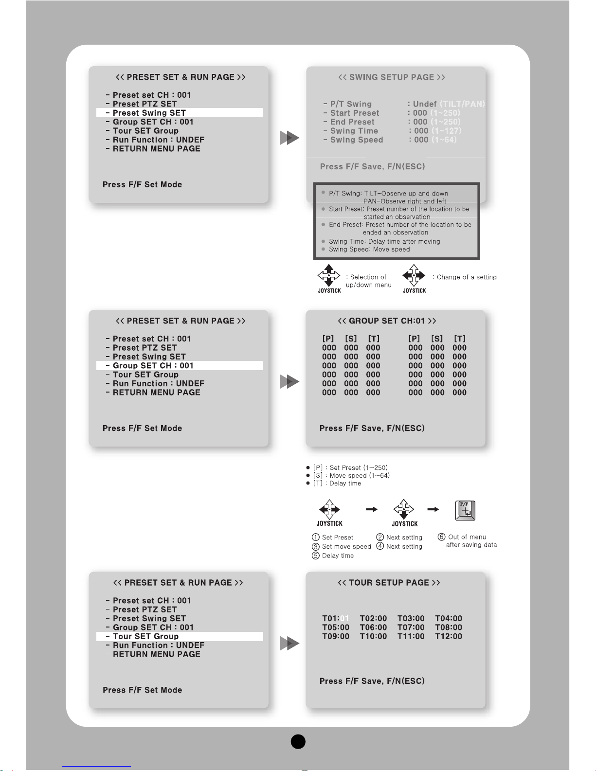
③ Preset Swing SET : Set Preset Swing Move next
SWING page for the setting, if user presses F/F
key in the state of selection of the menu
※ The preset must be set before the setting as Swing
Is a function to repeat an auto observation of 2
Preset points user fixes in Preset set
④ GROUP SET: User can set maximum 12 groups.
Select a channel then move to next page after
pressing F/F key
※ The Preset point in the Group that 12 Preset points
are set is observed repeatedly and order with regular
speed and time.
Page 21
20
⑤ Tour SET Group : User can set continual Group motion that can be put 12 Groups in 1 Tour Move to the
setting page if user presses F/F key on this menu
■
The Group user wants to set must be set previously
※ Setting is only possible when Preset is already set in the state of setting of Swing, Group, Tour if not, it displays the
message “Sorry Undefined”.
⑥ Run Function : Operate one of SWING/ *Set / Stop order with a control keyboard without menu GROUP
/ TOUR / TRACE. (It is operated on the screen automatically after end of OSD menu)
■
User can look at how to set “TRACE at TRACE SET PAGE”
⑦ RETURN MENU PAGE : Move to a prior menu page when control the joystick Right/Left in the Selection
of this menu.
21. TRACE SET PAGE
Set TRACE.
User can regenerate and save a change of the
unrestricted location of ZOOM In/Out and a position of
the camera by hand-worked control with a joystick.
User can see the screen when moves the joystick to
Right/Left after fixing the cursor on the menu
■
How to set TRACE
Move to [SET] after pressing
Check - Control scenes that user wants by
hand-worked with a joystick after the message.
“Set Trace: OO%” on the middle of the screen. If user
finishes this part, Move to [SAVE] with
It goes a prior menu after being saved data if user
presses with and displays the message “Save
TRACE”
Page 22
21
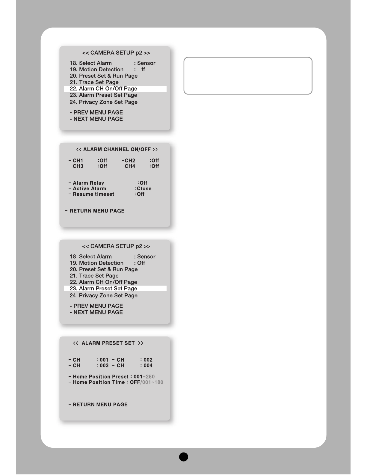
22. ALRAM CHANNEL ON/OFF
- CH On/Off : Alarm Input - Each channel can be ON/ OFF
- Alarm Relay : It can be set On or not when ALARM
OUTPUT PORT operates wrong.
- Active Alarm : It selects ACTIVE-OPEN or ACTIVECLOSE by alarm signal tangency when it is
detected. It is active when alarm input is open in
ACTIVE-OPEN and it is active when alarm input is
close in ACTIVE-CLOSE.
- Resume Time Set : It can select the stay time that
the camera moves to the place alarming to observe
where the detective signal is sensed.
User can set it for 1sec to 180sec and operate
GROUP, TOUR, SWING again in a preset time.
The SWING, GROUP, TOUR are operated in a
preset time when user stops the operating joystick
in the case of disconnecting with the ALARM.
Press SWING, GROUP, TOUR keys without
running of the joystick to stop the operating
completely (*Stopping the operating with the joystick
affects the SET function.)
23. ALARM PRESET SET PAGE
■
The camera can move to a preset point automatically when it is detected in each ALRAM
CHANNEL.
■
Set a preset point previously to move if anything
wrong, then use that sets the preset number into
each ALARM CHANNEL.
■
PRESET is out of connecting in ALARM CHANNEL
No. “0”
■
User can select PRESET number 1 to 250 and set it.
■
Home Position Preset
The camera automatically moves to where master
user set when another user controls the camera to
observe other area. (You can set 1~250 points)
■
Home Position Time
It sets the dwell time in Home Position Preset.
It automatically moves to where observes
ordinarily in the regular time that Master user set in
observation of other area, if set Home Position
Preset(You can set 1~180sec. Set control Home
Position Preset and Home Position Time together
for using this function.)
※ You can set ALARM setting MENU not only in CAMERA
SET MENU MODE, but also a KEYBOARD in direct
■
What is the ALARM function? : It operates to
observe the location of the camera which is
memorized previously in the situation of the
warning signal or trespassers by using a sensor.
Page 23
22
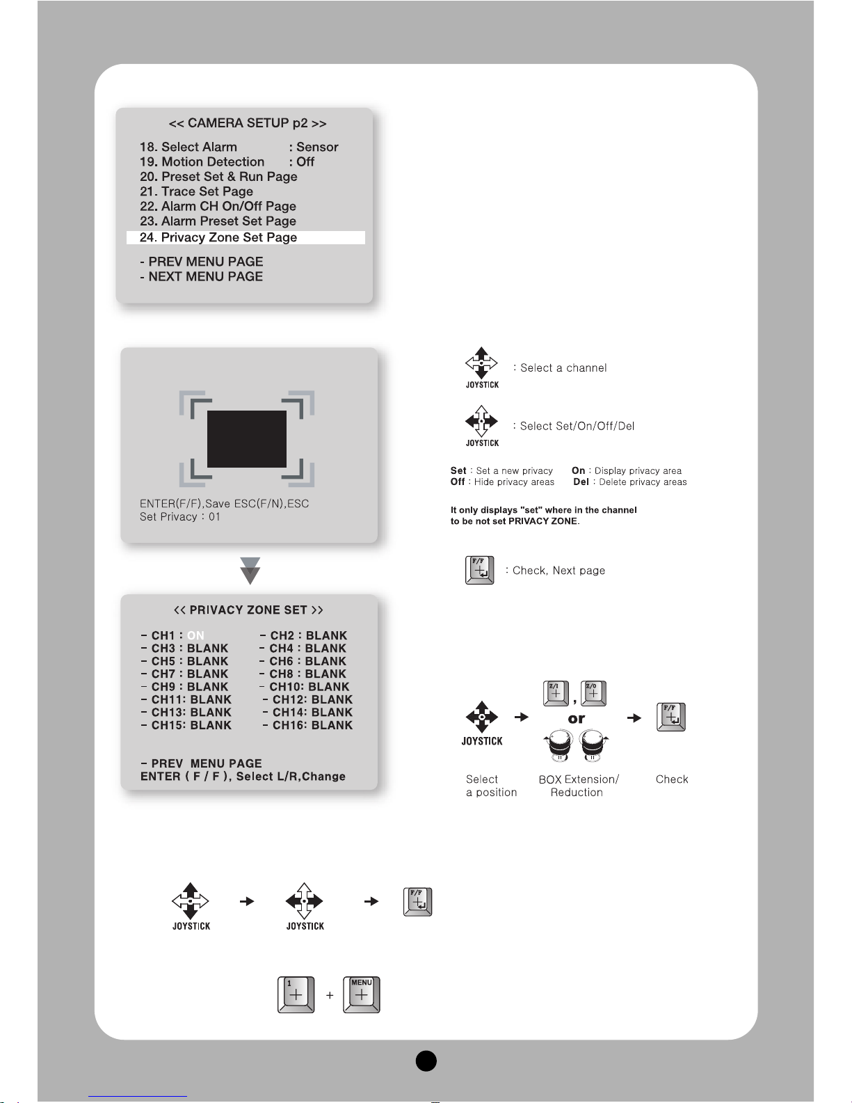
24. PRIVARCY ZONE SET
Max 16 privacy zones can be configured for the
protection of privacy.
■ How to set privacy zone
In <<PRIVACY ZONE SET>> menu, select the
channel that you want by a joystick, then move to
the next page if you press the [F/F] key
①
②
③
④ Fix the black square on the middle of area that
you want to hide by a joystick, then go back to
the previous page by [F/F] key after controlling
the size of the square by [Z/I], [Z/O] key and
saving it.
⑤ The Channel is changed BLANK to ‘OFF’.
The screen displays the black square, if you change the CH ON as the left picture.
⑥ Out of OSD MENU
Page 24
23
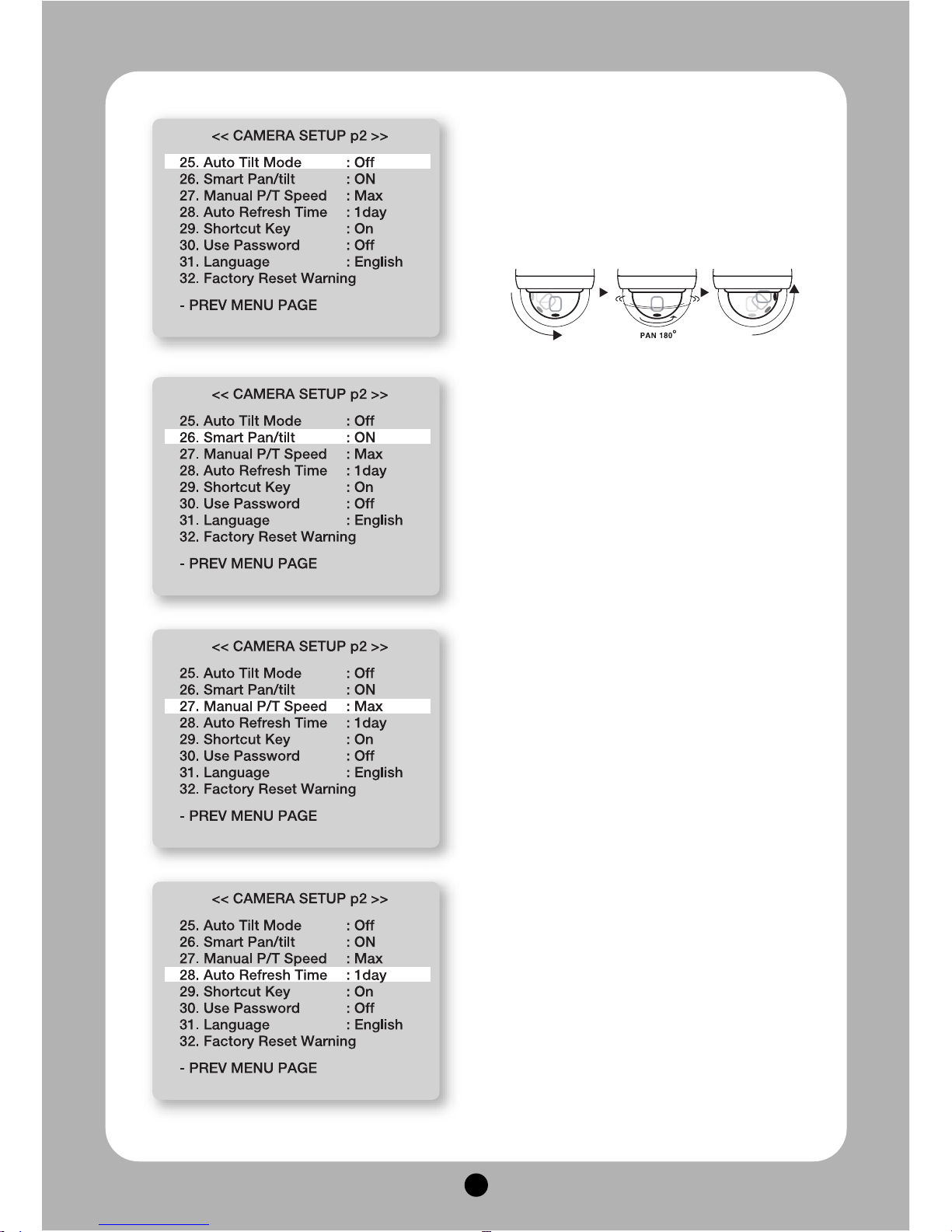
25. AUTO TILT MODE
The PAN is turned in a 180°degree arc automatically
when the angle of the camera moves down to the
maximum degree, therefore, it is possible to track
objects continuously
26. SMART PANTILT
It is a function that P/T speed is getting slower as
Zoom in.
It is hard to observe objects with the high PANTILT
speed in operating of Zoon In
This function makes the speed less automatically for
the effective observation
27. MANUAL P/T SPEED
User can control the maximum speed in controlling of
up and down.
It can be set Low, Medium, Max and one turn (360°
/sec) is possible in Max.
28. AUTO REFRESH TIME
Auto refresh can be set from 1 to 7days (each) for
good focus performance
Page 25
24
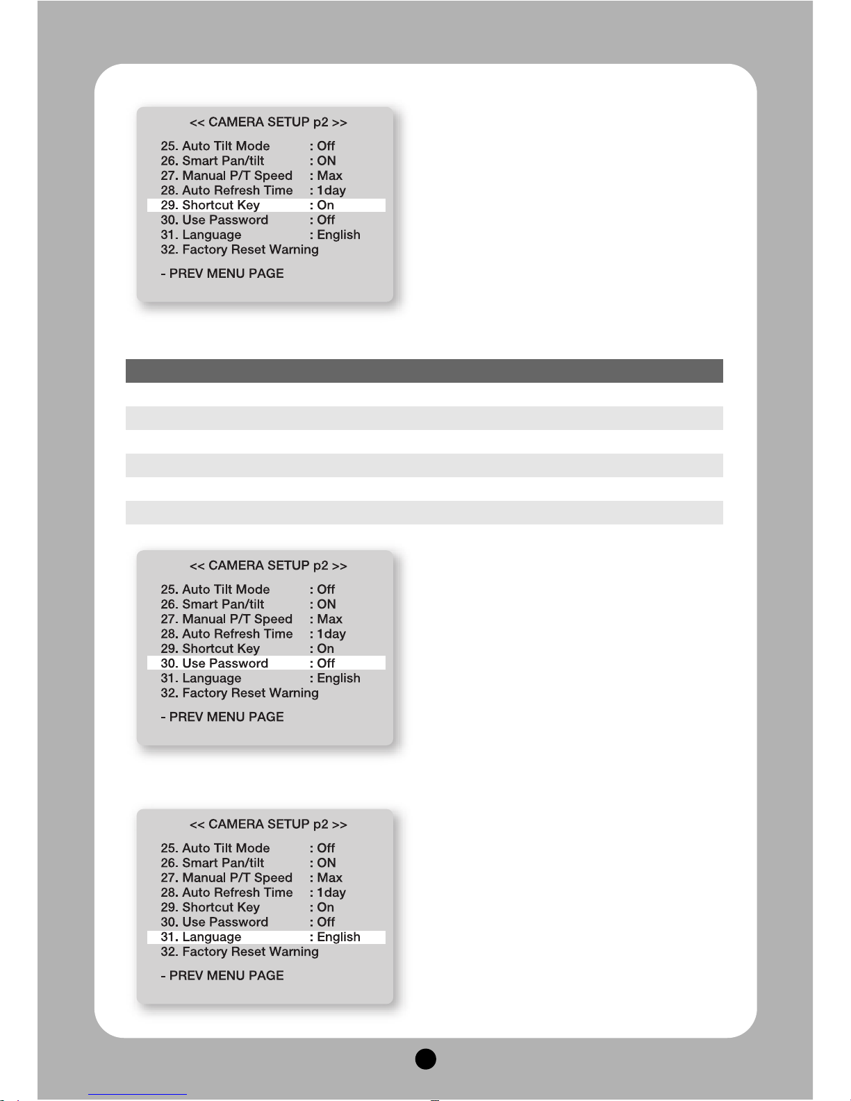
29. SHORTCUT KEY
The Shortcut Key can make some of the functions to
perform faster and easily.
30. USE PASSWORD
- input the password
- available set On/Off mode; off mode is factory set
- press the F/F button as On mode
- A window will be pop-up for input Old and New
passwords. Old password is set as ‘0000’. To input
a new password, use the joystick as up, down, right,
and left
- Press F/F button to save the new password. The
new password will be needed when access the
OSD mode
31. LANGUAGE
English, Portuguese, Polish
★★
How to use shortcut key (All protocols is operated it at the same way )
Function Operation Function Operation
Group 1 51 + Preset Run Trace 66 + Preset
Group 2 52 + Preset Run Spiral 67 + Preset
Group 12 62 + Preset B/W Mode 68 + Preset
Run Tour 63 + Preset Color Mode 69 + Preset
Run Pan Swing 64 + Preset OSD Menu ON/OFF 95 + Preset
Run Tilt Swing 65 + Preset
Page 26
25
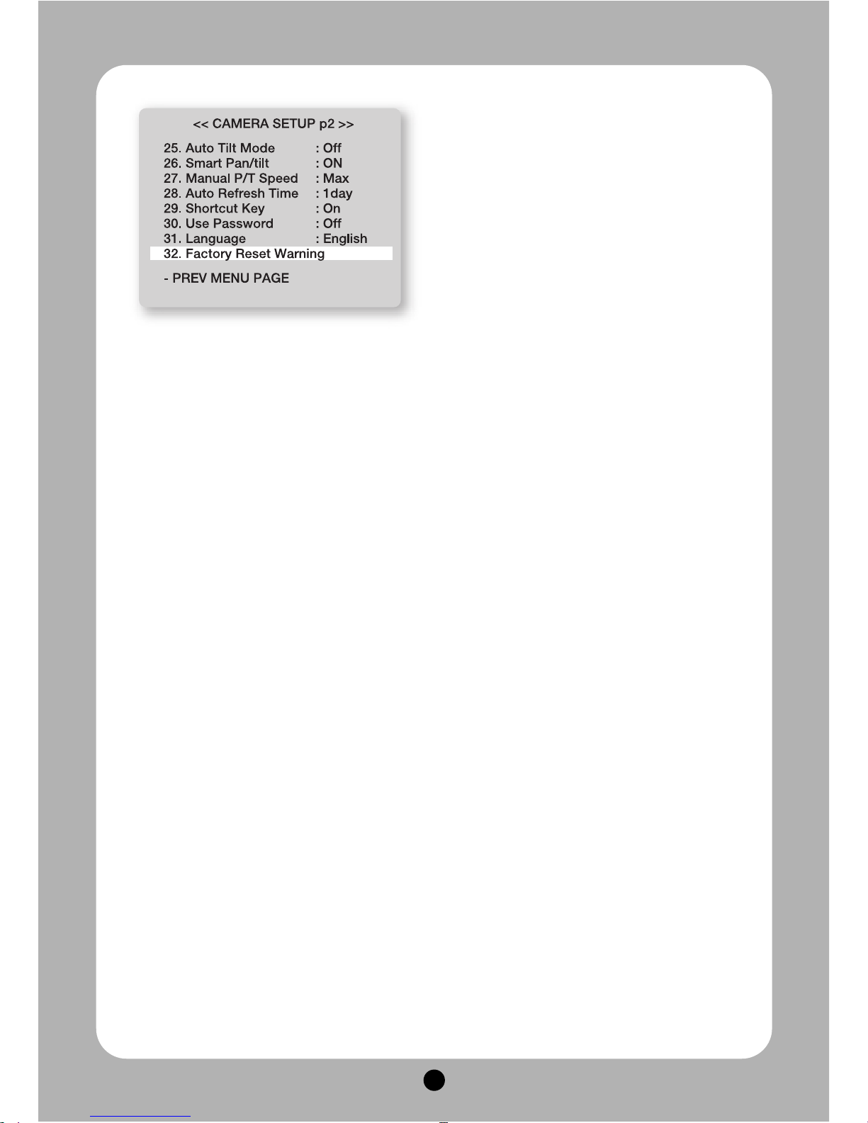
32. FACTORY RESET WARNING
Please be careful of that all setting data of OSD
MENU are reset into the first default when operates
FACTORY RESET WARNING.
The setting data of Preset, Swing, Group, Tour,
Trace, also is deleted all
Page 27
26
Ⅳ.
Functional Setting by the Keyboard
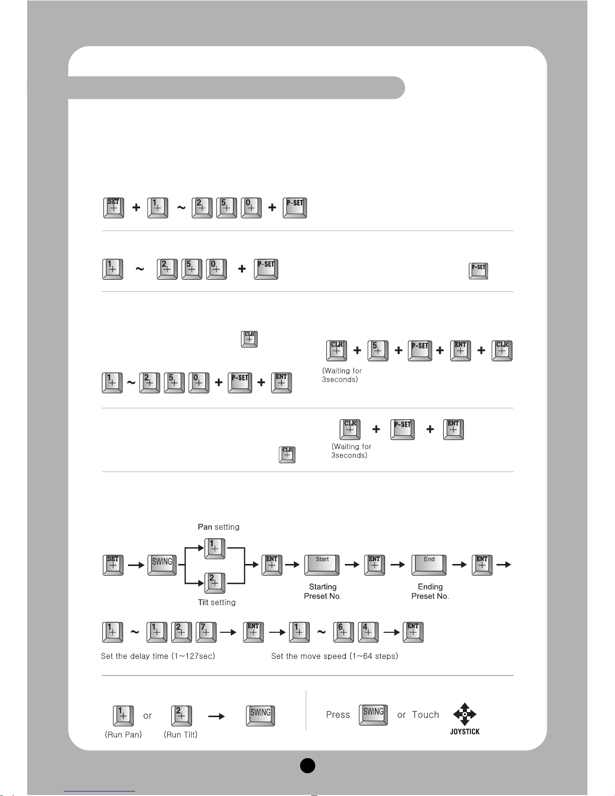
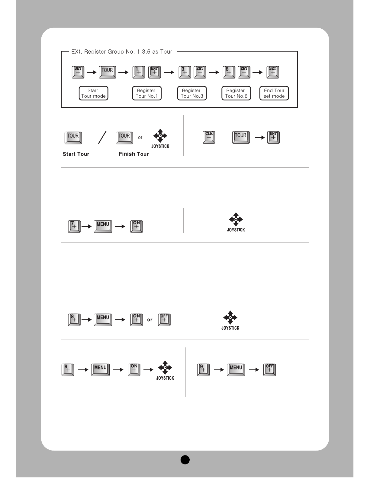
1. Preset setting
You can set Preset point up to 250.
① Preset Input.
② Preset Move
③ Delete a separate Preset
Go on in order as below when the sound is
heard in 3 seconds after pressing
Ex) Delete 5th Preset
2. Swing setting
① Swing Input
② Operation of Swing ③ End of Swing
④ Delete all Preset
Go on in order as the right picture when the
sound is heard in 3 seconds after pressing
Preset setting can be set 1 to 250 sequentially
after moves the camera to where you want
The camera moves to the preset point, if you
press Preset No. that you want and
Page 28
27
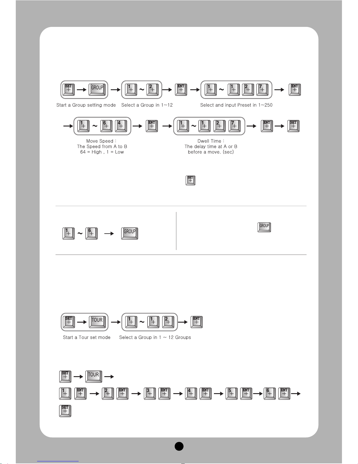
3. Group setting
① Start Group setting mode
- Set Preset No. again if you want to input it continuously.
- Set a GROUP again from the first after ending with Key , if you would like to finish Preset input in
one group to input next Group.
4. Tour setting
① Tour set mode
■ Repeat input in continual input
You can stop it when pressing or using a
joystick
② Start a Group ③ Stop the Group
Page 29
28
5. Spiral Function
It is a function to observe objects in the spiral direction.
6. PTZ Trace
It memorizes P/T/Z motions for 200sec, then operates them at the same Trace.
① Start / End Trace
② Set Trace ③ Delete Trace
① Spiral observation ‘ON’②End
② Start / End Tour ③ Delete Tour
Page 30
29
Ⅴ.
OSD MESSAGE DISCRIPTION
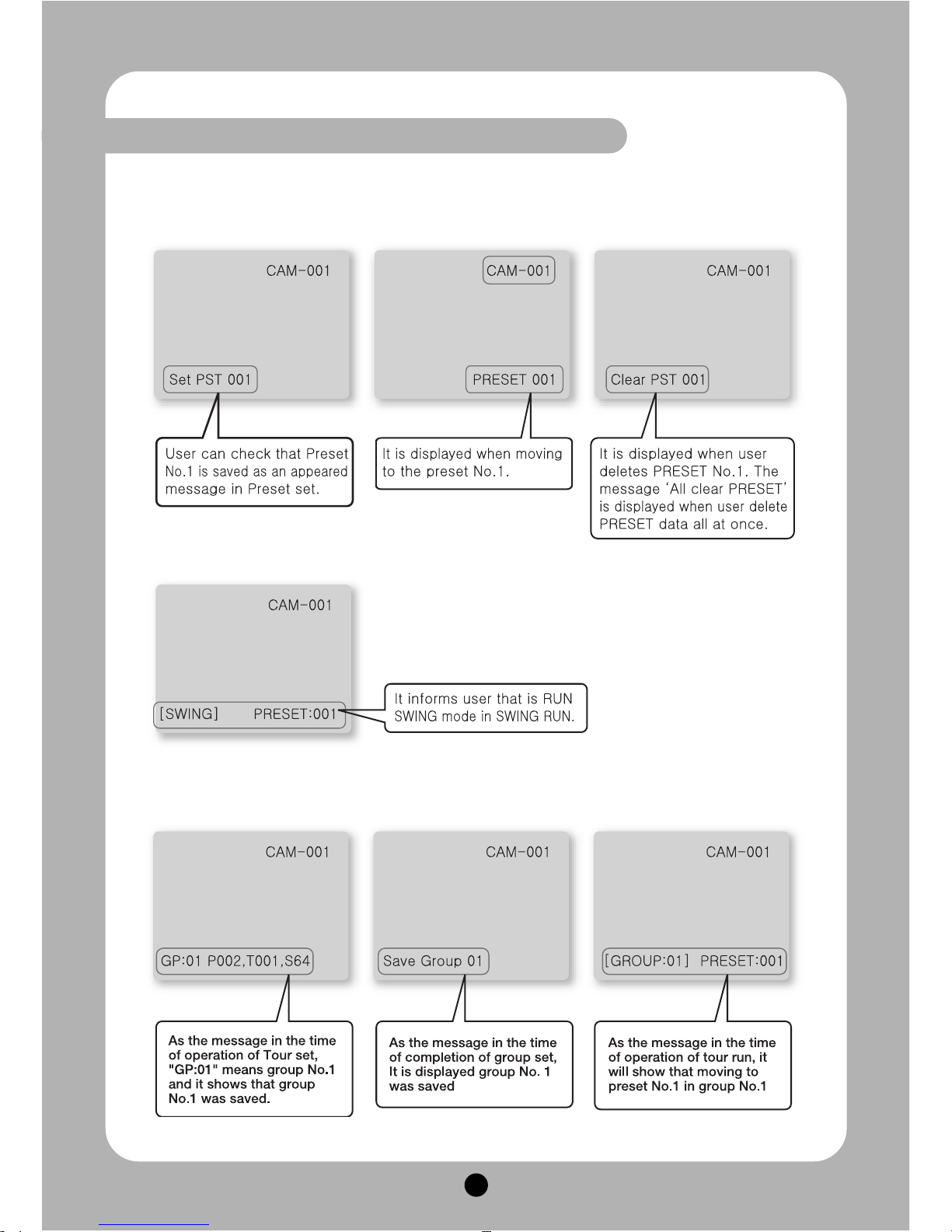
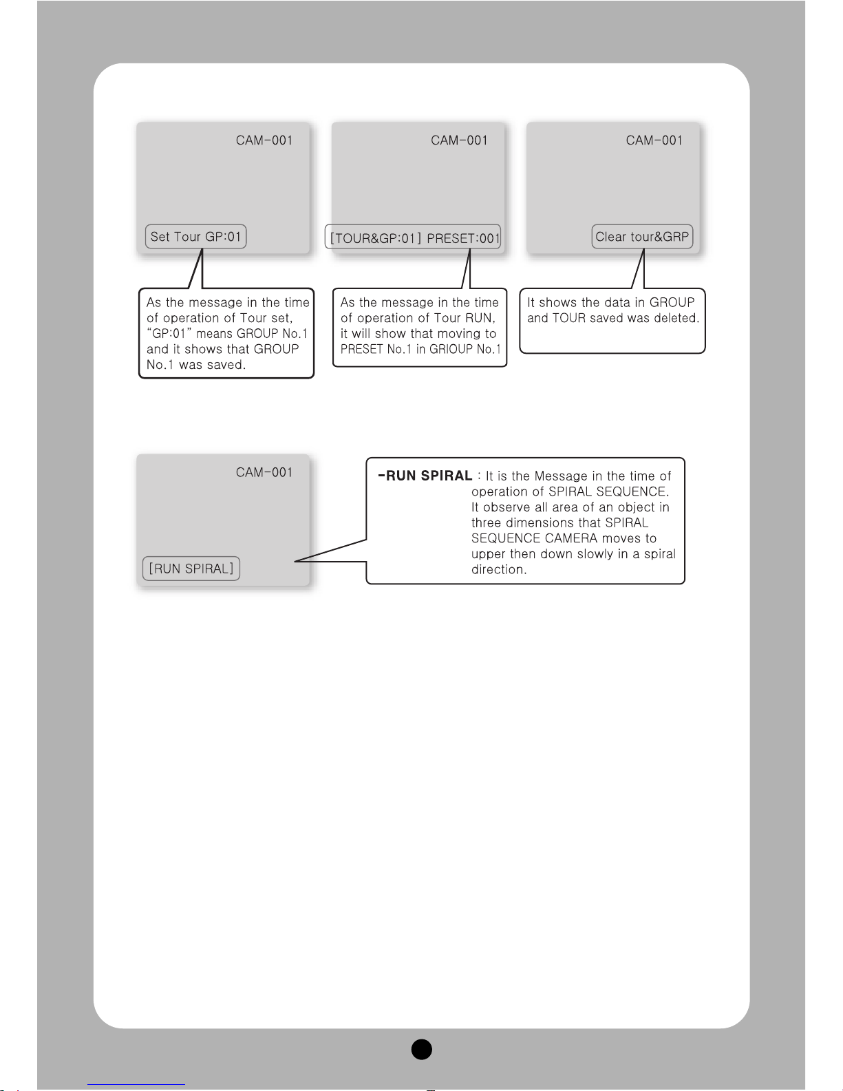
1. PRESET MESSAGE
Page 31
30
Page 32
31
Ⅵ.
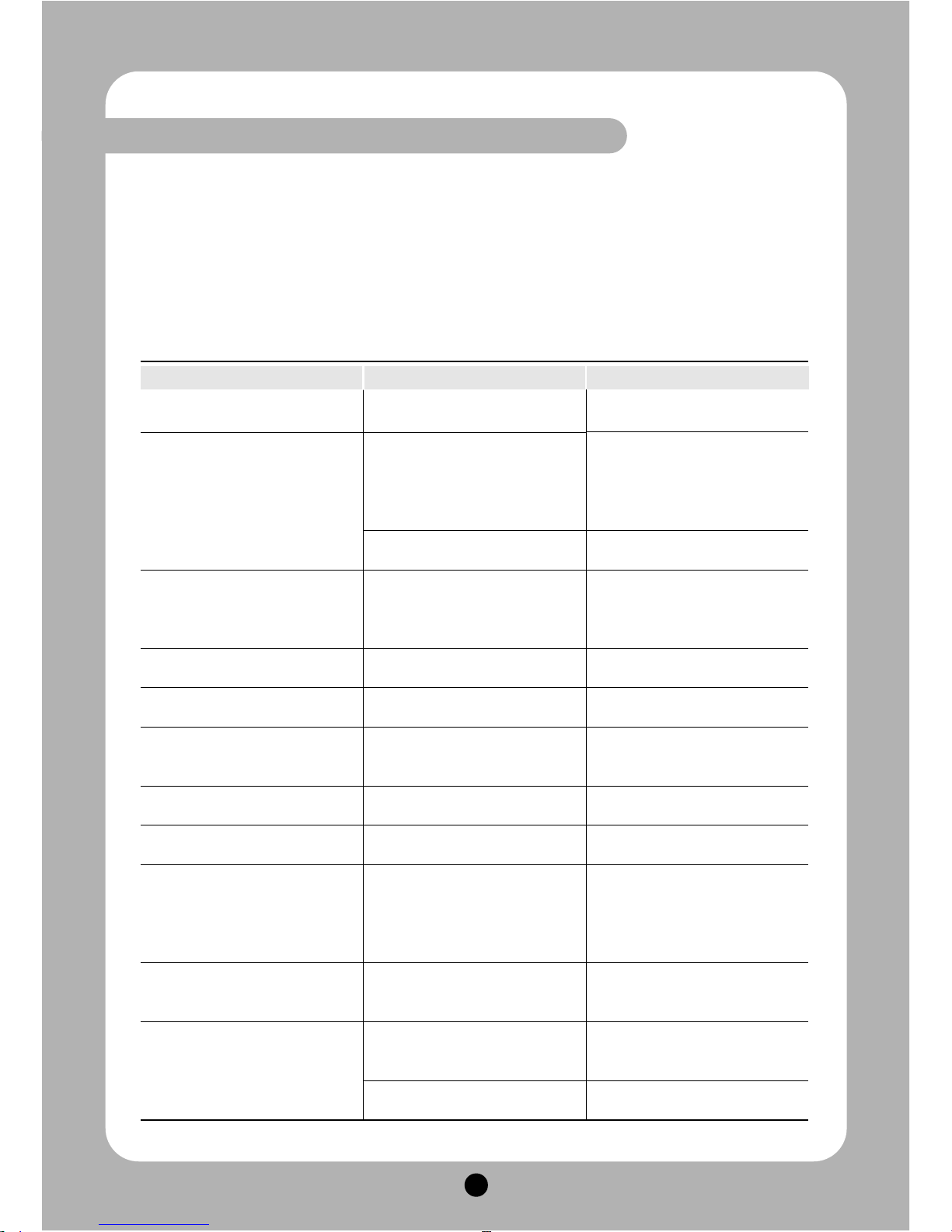
TROUBLE SHOOTING
1. You must turn off the power switch before installation of this equipment
2. Avoid installation places where it is the ultimate cold, hot, and humid.
3. Use a power supply of AC24V, 1.5A output.
4. Please be careful that you connect respective wires without mismatching in installation.
5. Check the controlled cable’s insulation connecting to exterior and supply to power sources.
6. Please keep the equipment from impact and strong rolling in installation or in use because
of the caution of troubles.
TROUBLE SHOOTING CHECK POINT MAINTENANCE
Power do not turn on
Power turned on but do not operate.
The acting of pan/tilt is not good.
Either it is not clean on screen or it is
appeared rolling TV lines on screen.
It is not focus on the object by
manual.
It is continuously appeared error
message of “P/T POSITION
ERROR”
It is continuously appeared error
message of “SORRY NOT MEMORY”
It does not alarm relay ON in active
alarm state.
Even if sensor is normal, it is
activated abnormal.
When it occurred alarm state, it is
not exactly presser position or
different.
When it activate alarm state, there is
no sign on the keyboard controller
Does the electric power supply into
the equipment normally?
In operating, Does the LED beside
power switch light to red?
Did you select to RS485 or RS422
exactly?
Did you turn on the ending terminal
register? (The ending terminal
resister can be switch on/off, if you
loose cover of dome.)
Is the power supply AC24V, 1.5A
output?
Did you change min. distance in the
set menu?
Did the under body of camera press
or put between others?
Did you set the related function?
Did you set ON the alarm relay in
the set mode?
Is it correct alarm active setting
status and sensor is either open or
close?
Did you set the preset in the set
mode?
Did you use the exclusive control
keyboard?
Yes, I do.
Check either LED is lit or not in the
connector part of back box.
•Check the connecting status of
data cable, if it is not lit.
•If it is lit, check address and
communication speed setting of
DIP switches.
Check the status at number 2 of
option DIP switches.
Switch on the ending terminal
resister of camera to be set in most
far away.
Change the adapter has higher
current charge than used adapter.
Change min. distance in the set
menu.
Get rid of something that press
camera, and check either camera is
rotating in softly or not.
Please refer to manual book and
setting the function you want
Please select on to enable alarm
relay in the set mode
Please set alarm active mode
setting as to correct to connect
status of sensor (it means either
sensor is open or close) in the set
mode.
Check setting status of the alarm
preset in the set mode.
It is need to use an exclusive control
keyboard so that the alarm sound is
activated on the controller
Please select on to enable alarm of
the related camera.
Page 33
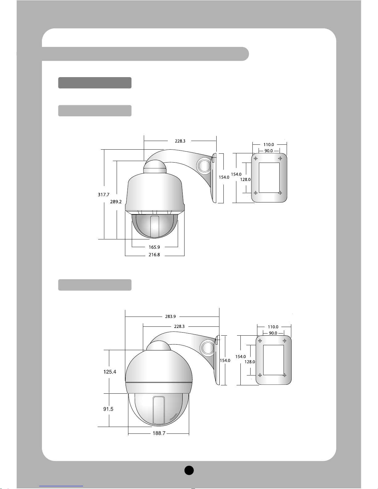
32
Ⅶ.
DIMENSIONS
Wall mount bracket
Outdoor Type
Indoor Type
Page 34
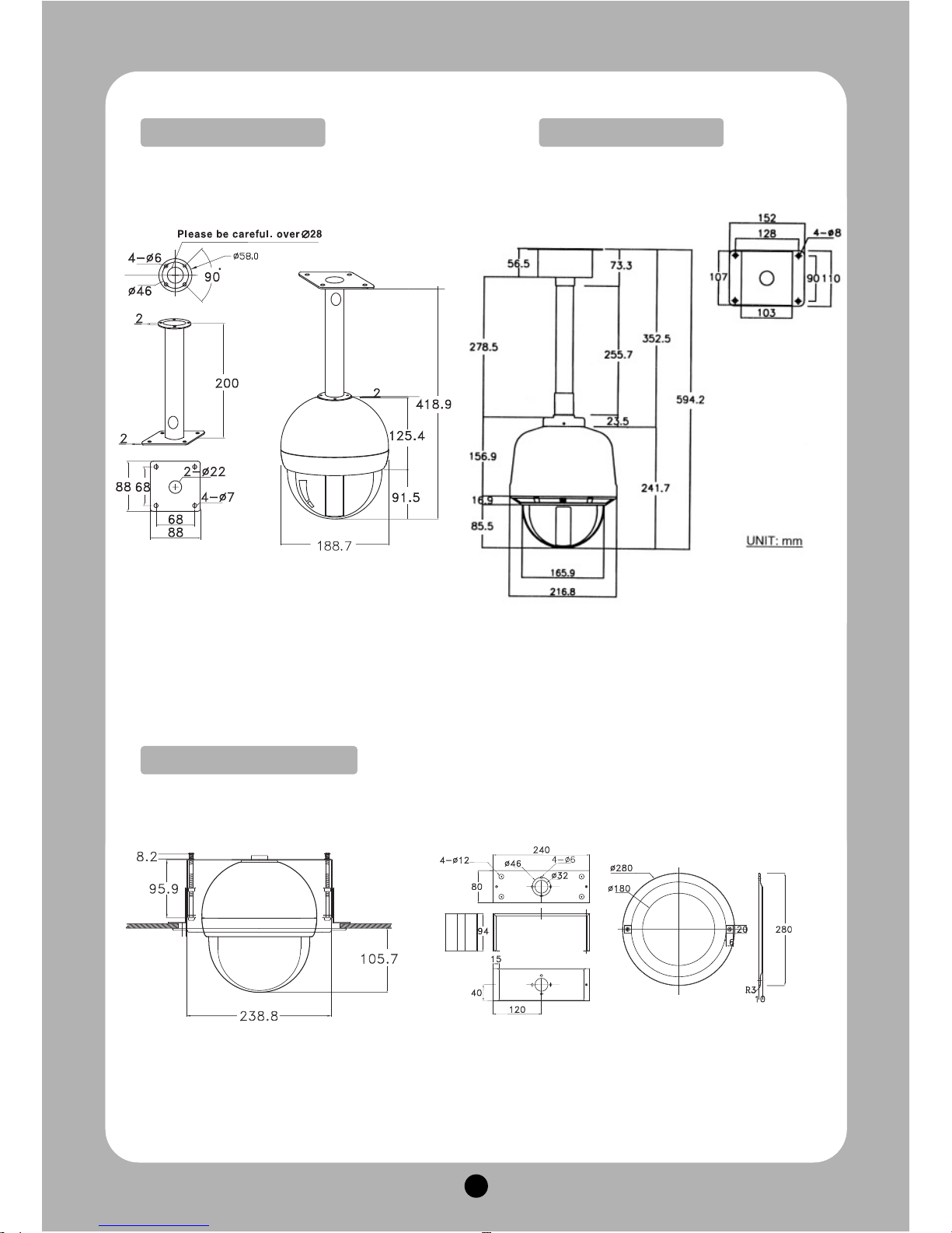
33
Outdoor Type
In-ceiling mount bracket
Indoor Type
Page 35
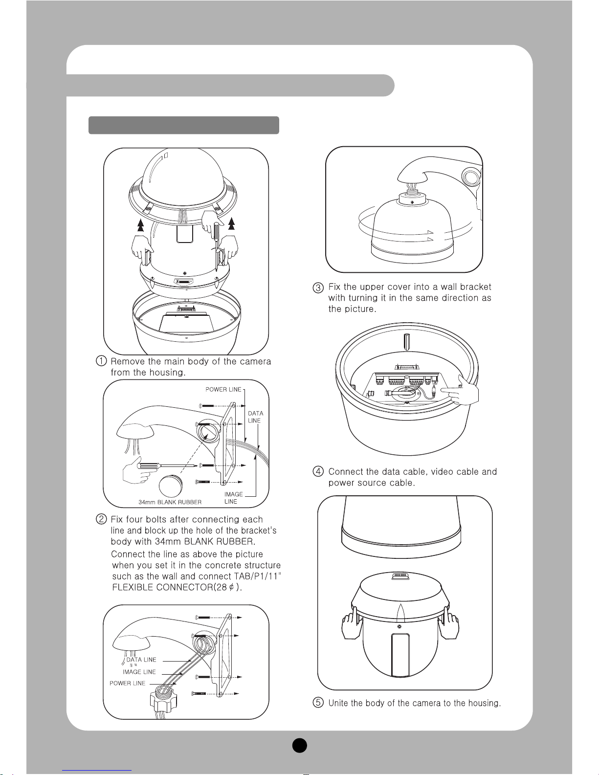
34
Ⅷ.
ASSEMBLY
DSC-30EWP Wall mount bracket
Page 36
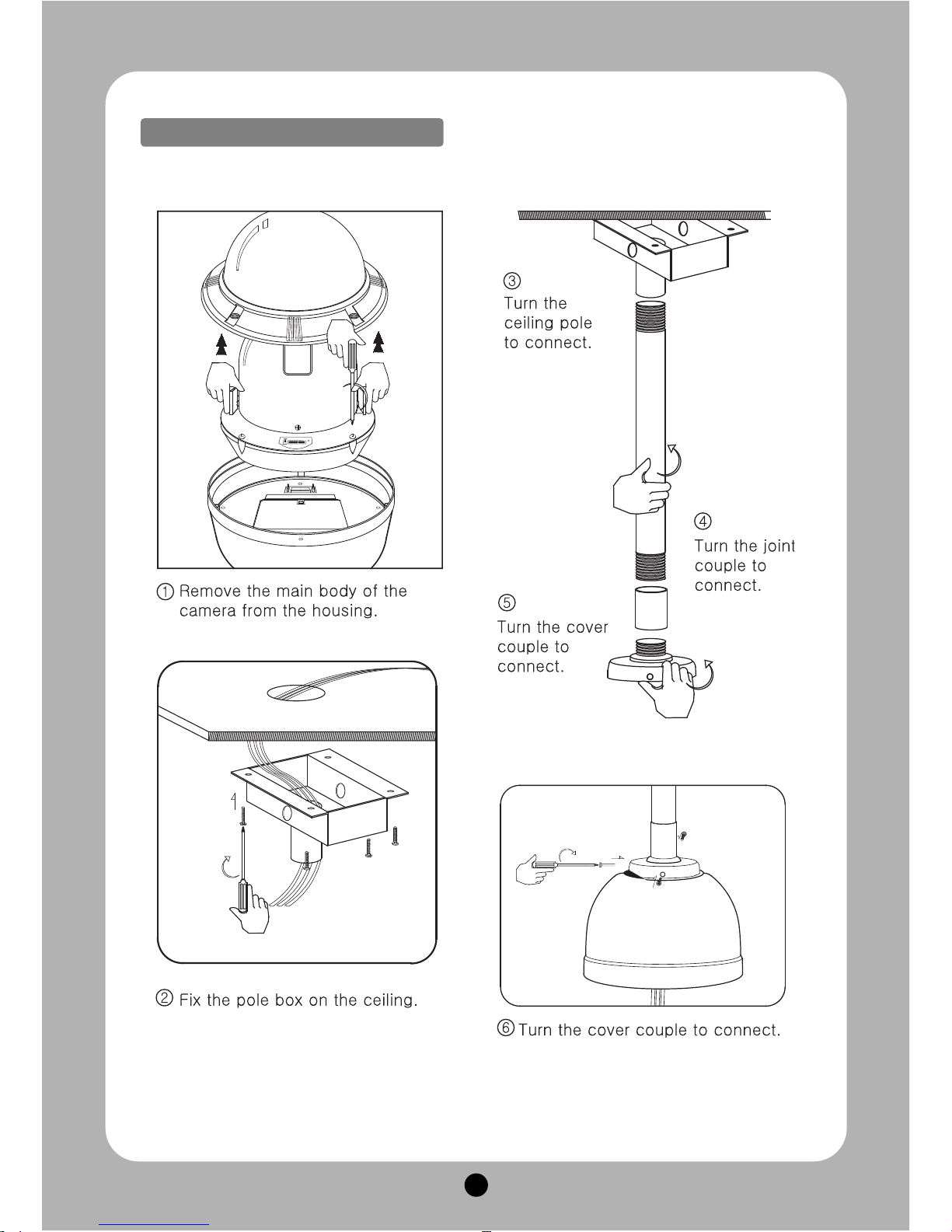
35
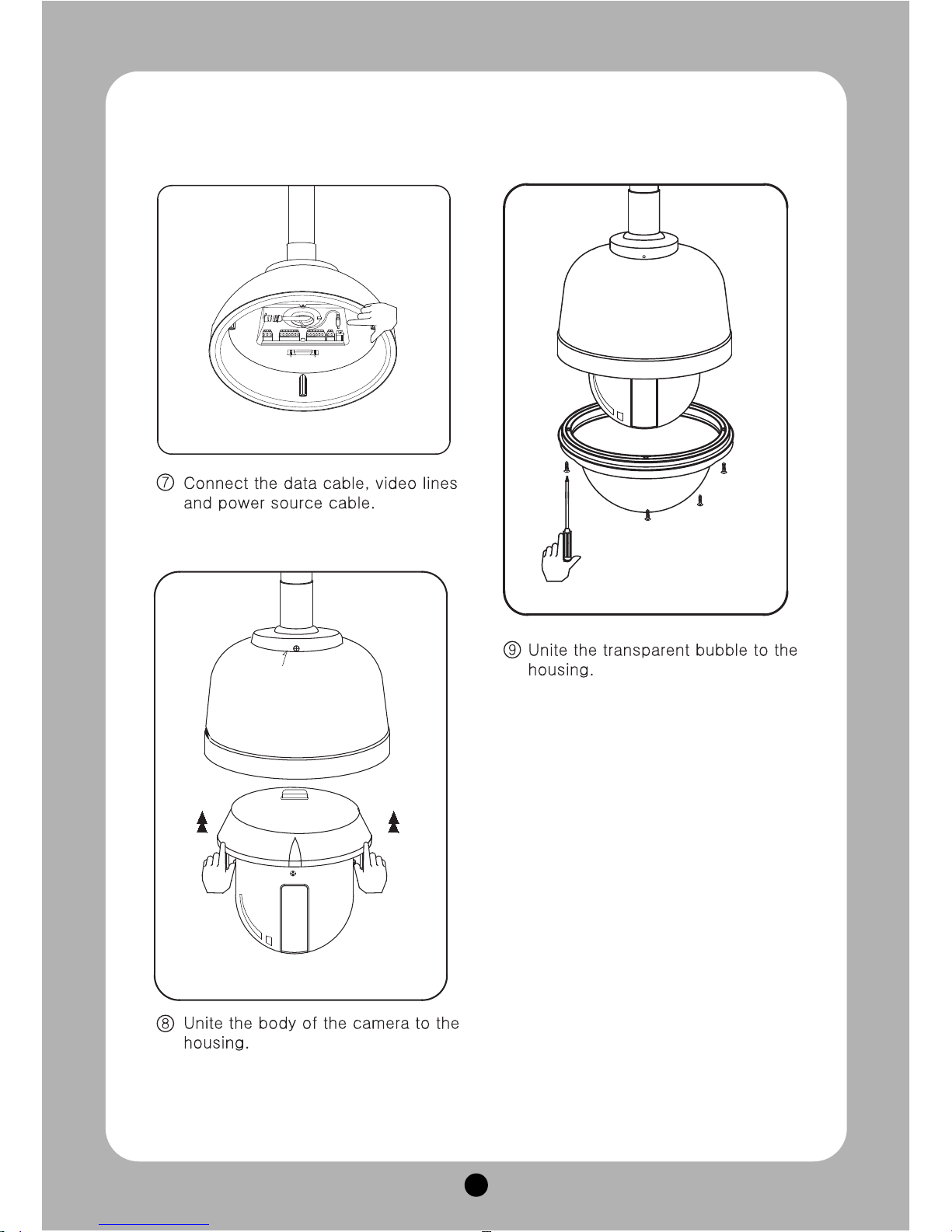
Assembly of outdoor dome with pole mount pendant
DSC-20EWP Wall mount bracket
Page 37
36
Page 38
37
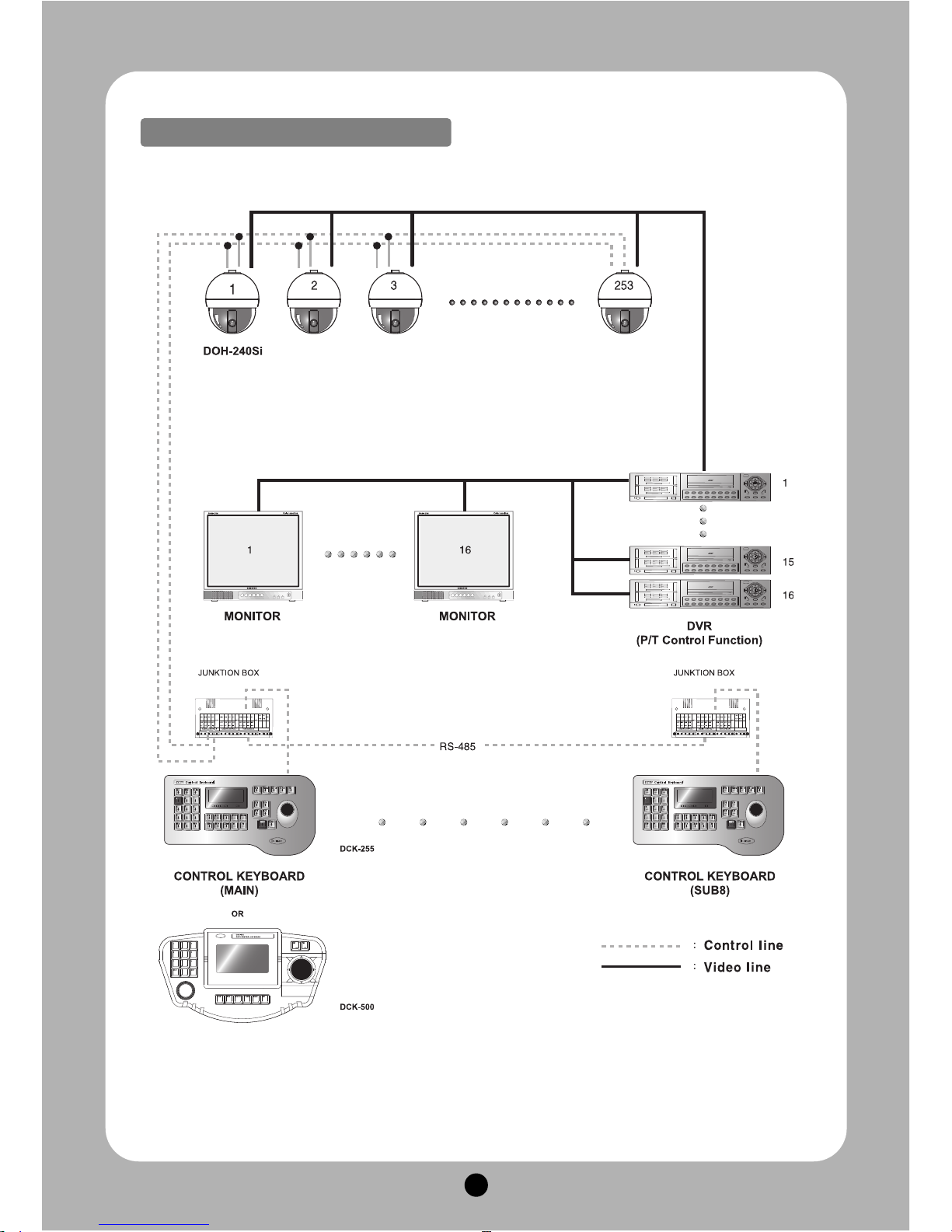
Main & Sub Keyboard configuration
Page 39
38
Ⅸ.
SPCIFICATIONS
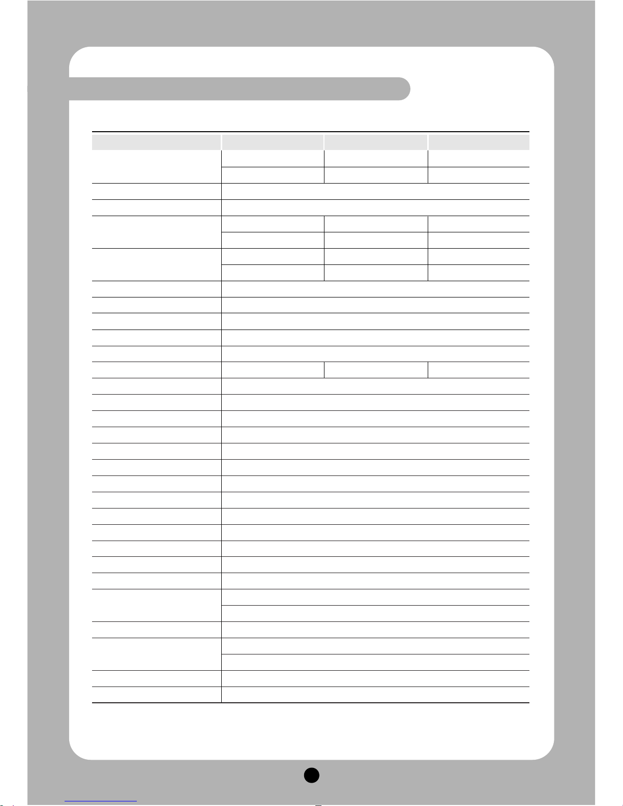
MODEL
27X Zoom 33X Zoom 37X Zoom
Image sensor
1/4" Sony Super HAD 1/4" Sony Super HAD 1/4" Sony Double
CCD CCD Density interline CCD
Effective pixels NTSC 768(H) × 494(V), PAL 752(H) × 582(V)
Horizontal resolution Color : 550 TVL, B/W 680 TVL
Lens (Digital Zoom)
27x Optical zoom(12x), 33x Optical zoom(12x), 37x Optical zoom(12x),
f=3.5-94.5mm f=3.5-115.5mm f=3.5-129.5mm
Angle of view
H : 55.5° ~2.24°, H : 55.5° ~1.77°, H : 55.5° ~1.59°,
V : 42.5°~1.79° V : 42.5°~1.33° V : 42.5°~1.19°
Minimum illumination 0.7 Lux , 0.1Lux(D&N), Min 0.00005Lux(DSS) / F1.6 (50IRE)
Luminance S/N ratio More than 52dB
Video output 1 Vp-p Composite video output 75
Ω
Focus mode Auto / Manual / Oneshot
SSNR Off / Low / Middle / High
WDR ××○
Back Light Control BLC / HLC
Shutter speed Auto / 1/120 ~ 1/120,000 sec
Sharpness control Level (0-10)
Stabilizer On/Off
Alarm in/out 4 Inputs / 1 Relay Output
Pan/Tilt angle 360° Endless / 92°
Preset point 250 Presets
Preset Speed Max 360°/sec (64 Levels)
Privacy zones masking 16 Zones
Operating temperature / -40°C ~ 50°C (-40°F ~ 122°F) (Outdoor Model) / Less than 90%RH
Operating humidity - 10°C ~ 50°C (-14°F ~ 122°F) (Indoor Model) / Less than 90%RH
Communiction system RS-485 / 422
Operating Fan/Heater Over than 45°C / Less than 5°C (Only Outdoor Model)
Dimensions
188.7mm(Diameter) × 216.9(Height)mm (Indoor Model)
216.8mm(Diameter) × 289.2(Height)mm (Outdoor Model)
Weight About 5.2Kg (Outdoor Model), About 3.1Kg (Indoor Model)
Construction
Aluminum body, Clear vandal bubble (PC) (Outdoor Model)
ABS body , Clear vandal bubble (PC) (Indoor Model)
Power consumption 18W (Max) Indoor Model / 21W (Max) Outdoor Model
Power supply AC24V, 60/50 Hz
Page 40

 Loading...