

Page 1

Petrol Powered Pressure Washers
User Manual
[Revision 1.0 May 2017]
READ THIS MANUAL CAREFULLY BEFORE USE – FAILURE TO DO SO MAY RESULT IN INJURY, PROPERTY
DAMAGE AND MAY VOID WARRANTY. • KEEP THIS MANUAL FOR FUTURE REFERENCE. • Products covered by
this manual may vary in appearance, assembly, inclusions, specifications, description and packaging.
The product is NOT supplied with engine oil, although traces of oil from the manufacturing
process may be present. It is essential to add adequate engine oil of the correct type to the
engine before use – see Checking and Changing Engine Oil. Failure to add engine oil will void the
product warranty.
E&OE © 2017 Jet-USA
Page 2

Petrol Powered Pressure Washers
E&OE © 2017 Jet-USA 2
Safety
Safety messages are designed to alert you to possible dangers or hazards that could cause death, injury or
equipment or property damage if not understood or followed. Safety messages have the following symbols:
You WILL be KILLED or
SERIOUSLY INJURED if you do
not follow instructions.
You CAN be KILLED or
SERIOUSLY INJURED if you do
not follow instructions.
You CAN be INJURED if you do
not follow instructions or
equipment damage may occur.
It is important that you read and
understand the instruction manual before
use and keep the manual in a safe place
for future reference. Safety information
presented here is generic in nature – some
advice may not be applicable to every
piece of equipment.
All safety precautions must be observed to
reduce the risk of personal injury when
operating the equipment.
The term "equipment" refers to your
product, be it electrical mains, battery or
petrol engine powered.
IMPORTANT – Handle the equipment
safely and carefully.
BEFORE USE - If you are not familiar with
the safe operation/handling of this
equipment, or are in any way unsure of any
aspect of suitability or correct use it for
your application, you should complete
training conducted by a person or
organization qualified in safe use and
operation of this equipment, including
fuel/electrical handling and safety.
WARNINGS
• Read all safety warnings and all
instructions. Failure to follow warnings
and instructions may result in electric
shock, fire and/or serious injury.
• Never run a combustion engine in
confined areas.
• Do not operate the equipment in
flammable or explosive environments,
such as in the presence of flammable
liquids, gases or dust. Engine and
equipment may create sparks or heat
that may ignite vapours, dust etc
• Keep clear of moving parts.
• This equipment may be a potential
source of electric shock if misused.
• Do not operate the equipment if it is
damaged, malfunctioning or is in an
excessively worn state.
• Do not allow others to use the
equipment unless they have read this
manual and are adequately trained.
• When using the equipment, basic
safety precautions detailed here must
always be followed to reduce the risk
of fire, electric shock, personal injury
and material damage.
• When wiring electrically powered
equipment, follow all electrical and
safety codes.
• Ensure all power sources conform to
equipment voltage requirements and
are disconnected before connecting
equipment.
General Work Area Safety
Work areas should be clean and well it.
Do not operate the equipment if
bystanders, animals etc are within
operating range of the equipment or the
general work area.
Personal Safety
Keep packaging away from children - risk
of suffocation! Operators must use the
equipment correctly. When using the
equipment, consider conditions and pay
due care to persons and property.
Prevent unintentional starting of the
equipment - ensure equipment and power
source switches are in the OFF position
before connecting or moving the
equipment. Do not carry equipment with
hands/fingers touching any controls.
Remove any tools or other items that are
not a part of the equipment from it before
starting or switching on.
Stay alert and use common sense when
operating equipment. Do not overreach.
Keep proper footing and balance at all
times. Do not use equipment when tired or
under the influence of drugs, alcohol or
medication. This equipment is not intended
for use by persons with reduced physical,
sensory or mental capabilities.
You must wear appropriate protective
equipment when operating, servicing, or
when in the operating area of the
equipment to help protect from serious
injury, including eye injury, inhalation of
toxic fumes, burns, and hearing loss.
Always wear eye protection. Protective
equipment such as respirators, non-skid
safety shoes, hard hat, hearing protection
etc should be used for appropriate
conditions. Other people nearby should
also wear appropriate personal protective
equipment. Do not wear loose clothing or
jewellery, which can be caught in moving
parts. Keep hair and clothing away from
the equipment.
If devices are provided for the connection
of dust extraction and collection facilities,
ensure these are connected and properly
used. Use of dust collection can reduce
dust-related hazards.
General Equipment Use and Care
Do not force the equipment. Use the
correct equipment for your application. The
correct equipment will perform better and
be safer within its design parameters. Do
not use the equipment if the ON/OFF
switch malfunctions – any equipment that
cannot be controlled with the ON/OFF
switch is dangerous and must be repaired.
Use the equipment and accessories etc. in
accordance with these instructions,
considering working conditions and the
work to be performed. Using the equipment
for operations different from those intended
could result in hazardous situations.
Before use, inspect the equipment for
misalignment or binding of moving parts,
loose components, damage or any other
condition that may affect its operation. If
damaged, have the equipment repaired by
an authorized service centre or technician
before use.
Always keep the equipment and
accessories (cutting tools, nozzles, bits
etc) properly maintained. Keep the
equipment, controls and handles dry and
free from dirt, oil and grease.
Store the equipment out of reach of
children or untrained persons. To avoid
burns or fire hazards, let the equipment
cool completely before transporting or
storing. Never place the equipment in
places where there are flammable
materials, combustible gases or
combustible liquids etc.
The equipment is not weatherproof, and
should not be stored in direct sunlight, at
high ambient temperatures or locations
that are damp or very humid.
Pressure Washer Use and Care
• The pressure washer creates very
high pressures that can puncture skin,
cause severe injury and/or poison
blood. Do not direct the high-pressure
spray at any person, animal, electrical
equipment, equipment or items that
can be damaged by high-pressure
water spray or the machine itself.
• Use only hoses, fittings and couplings
supplied or recommended by the
manufacturer.
• Do not allow any persons, animals etc
to be within 20m (60') of the
equipment when in use.
• Do not operate the pump without a
liquid source to draw in.
• Maintain the machine and hoses in
good operating condition.
• Operate the equipment on solid, level
surfaces only. Do not hold or suspend
the equipment by hoses or other
unstable means.
Page 3

Petrol Powered Pressure Washers
E&OE © 2017 Jet-USA 3
General Fuel Safety
Petrol/fuel/gasoline is extremely
flammable – keep clear of
naked flames or other ignition
sources.
• Do not spill fuel. If you spill fuel, wipe
it from equipment immediately – if fuel
gets on your clothing, change them
immediately
• Do not smoke near fuel.
• Always shut off the engine before
refuelling.
• Do not refuel a hot engine.
• Open the fuel cap carefully to allow
any pressure build-up in the tank to
release slowly.
• Always refuel in well ventilated areas.
• Always check for fuel leakage. If fuel
leakage is found, do not start or run
the engine until all leaks are fixed.
General Service Information
• Have the equipment serviced or
repaired at authorized service centres
by qualified personnel only.
• Replacement parts must be original
equipment manufacturer (OEM) to
help ensure that equipment safety is
maintained.
• Do not attempt any maintenance or
repair work not described in this
instruction manual.
• After use, the equipment and
components may still be hot – allow
the equipment to cool and disconnect
spark plugs and/or electrical power
sources and/or batteries from it before
making adjustments, changing
accessories or performing repair or
maintenance.
• Do not make adjustments while the
equipment is running.
• Perform all service related activities
under suitable conditions, such as a
workshop etc.
• Replace any worn, damaged or
missing warning labels immediately.
• Do not clean equipment with solvents,
flammable liquids or harsh abrasives.
DANGER
Running combustion engines in confined areas
CAN KILL IN MINUTES. Engine exhaust fumes
contain carbon-monoxide – a deadly gas that
you cannot smell or see.
NEVER run a combustion engine in confined
areas EVEN IF windows and doors are open.
ONLY run petrol engines OUTDOORS and away
from doors, windows and vents.
Do not operate the equipment in hazardous locations, such
as where there may be a risk of fire or explosions from
flammable liquids, gases or dust.
Do not operate the equipment in confined areas where
exhaust gases, smoke or fumes could reach dangerous
concentrations.
Do not refuel a combustion engine while it is running, on or
hot.
Never smoke while refuelling combustion engines or
handling flammable substances.
For generators, the electrical output is potentially lethal and
must only be connected to a fixed electrical installation by
an appropriately licensed person.
Be aware that the equipment may include hazardous
components, such as blades, hot surfaces and moving
parts.
Handle any flammable substance with extreme caution.
Page 4

Petrol Powered Pressure Washers
E&OE © 2017 Jet-USA 4
Table of Contents
Safety ............................................................................................................................................. 2
Table of Contents .......................................................................................................................... 4
Applicable Models ........................................................................................................................ 6
Parts Identification and Assembly ............................................................................................... 7
CX580 - Parts Identification and Assembly .................................................................................................. 7
CX600 - Parts Identification and Assembly .................................................................................................. 9
CX630 - Parts Identification and Assembly ................................................................................................ 11
CX660 - Parts Identification and Assembly ................................................................................................ 13
MX400 – Parts Identification and Assembly .............................................................................................. 16
TX870 - Parts Identification and Assembly ................................................................................................ 18
Pumps, Hoses and Fittings ................................................................................................ ........ 20
Pumps ........................................................................................................................................................ 20
Sealed .................................................................................................................................................. 20
Non-Sealed .......................................................................................................................................... 21
Hoses and Fittings ..................................................................................................................................... 21
Using Connectors ................................................................................................................................ 22
Nozzles ................................................................................................................................................ 23
Detergent System ...................................................................................................................................... 24
Assembly – CX630 and CX660 ........................................................................................................... 24
Engines – Parts Identification .................................................................................................... 25
Before Use Checklist .................................................................................................................. 26
Engine Oil ................................................................................................................................................... 26
Air Filter ...................................................................................................................................................... 26
Fuel ............................................................................................................................................................ 26
Pump Oil – Non-Sealed Pumps Only ......................................................................................................... 26
Pump Breather – Non-Sealed Pumps Only ............................................................................................... 27
Connecting High-Pressure Hoses .............................................................................................................. 27
Connecting the Water Supply .................................................................................................................... 28
Mains Water Supply............................................................................................................................. 28
Using the Machine to Draw Water ....................................................................................................... 28
Engine Starting ........................................................................................................................... 29
Manual/Pull Starting ................................................................................................................................... 29
Stopping the Engine ................................................................................................................................... 29
Environmental Considerations ................................................................................................................... 30
Altitude ................................................................................................................................................. 30
Temperature ........................................................................................................................................ 30
Pressure Washer Operation ....................................................................................................... 31
Using the Lance ......................................................................................................................................... 31
Page 5

Petrol Powered Pressure Washers
E&OE © 2017 Jet-USA 5
Maintenance ................................................................................................................................ 32
Maintenance Schedule ............................................................................................................................... 32
Checking and Changing Engine Oil ........................................................................................................... 33
Checking, Cleaning or Replacing the Air Filter .......................................................................................... 35
Air Filter Inspection and Cleaning ........................................................................................................ 35
Air Filter Removal/Installation .............................................................................................................. 35
Spark Plug .................................................................................................................................................. 36
Spark Plug Cleaning and Gap Checking ............................................................................................. 36
Spark Plug Removal/Installation .......................................................................................................... 36
Checking and Changing Pump Oil – Non-Sealed Pumps Only ................................................................. 37
Checking, Cleaning or Replacing Water Inlet and Detergent Strainers ..................................................... 38
Strainer Inspection and Cleaning ........................................................................................................ 38
Strainer Removal/Installation ............................................................................................................... 38
Checking, Cleaning or Replacing the Fuel Strainer ................................................................................... 39
Fuel Strainer Inspection and Cleaning ................................................................................................ 39
Fuel Strainer Removal/Installation ....................................................................................................... 39
Transportation and Storage ....................................................................................................... 40
Troubleshooting .......................................................................................................................... 41
Specifications ............................................................................................................................. 44
Service and Maintenance Record .............................................................................................. 45
Page 6

Petrol Powered Pressure Washers
CX580
CX600
CX630
CX660
MX400
TX870
Applicable Models
This manual applies to the following Jet-USA pressure washers:
E&OE © 2017 Jet-USA 6
Page 7

Petrol Powered Pressure Washers
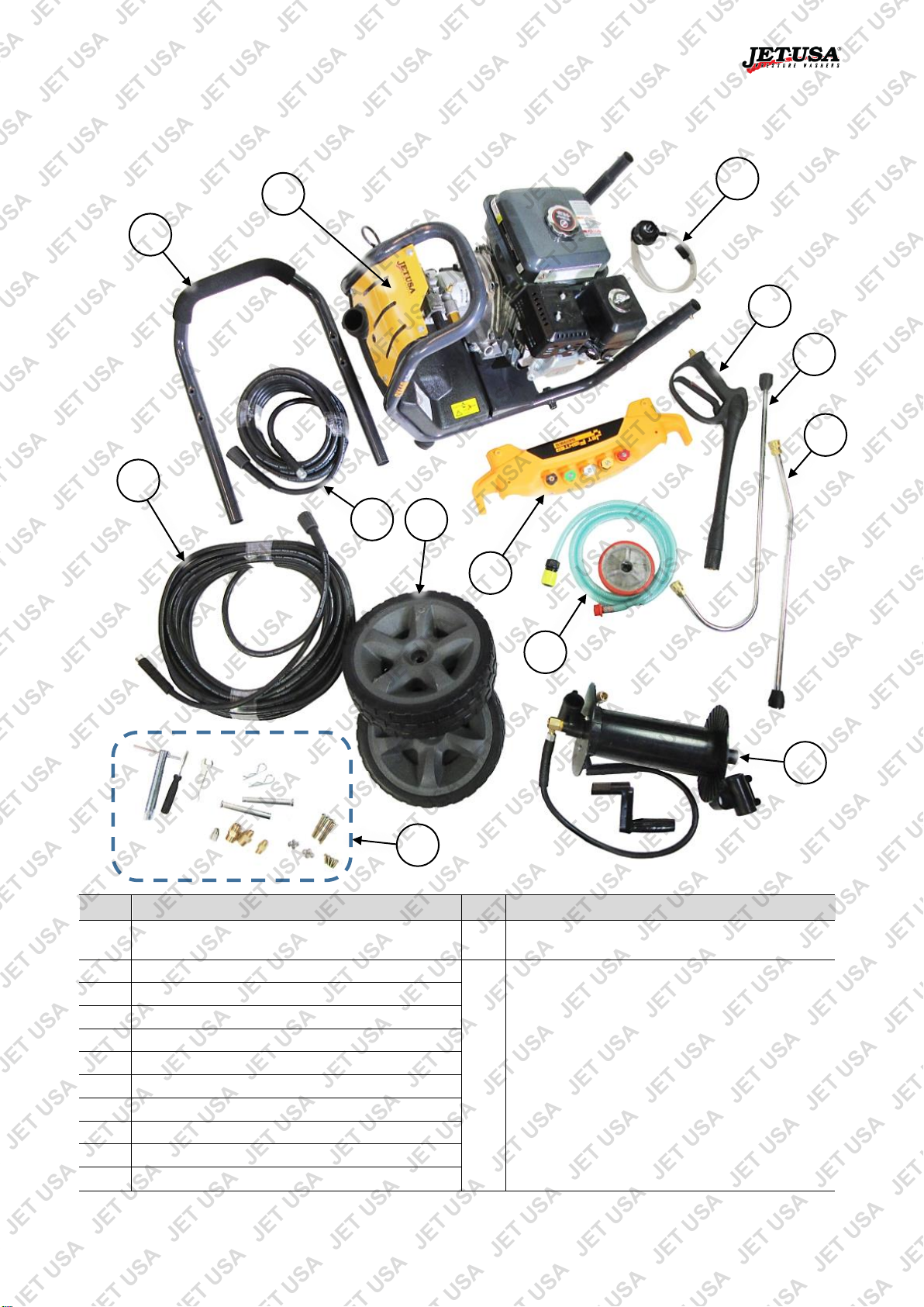
No.
Name
No.
Name
1
Frame / Engine / Pump Assembly
12
Fasteners / Fittings / Tools:
Wheel Axle (2)
M12 Nut (2)
M12 Washer (2)
M5x50 Screw (4)
M5 Nut (4)
M5 Washer (4)
M6x10 Screw (2)
M6 Extension Nut (2)
"Turbo" Nozzle Adaptor (may come preassembled)
5mm Allen Key (2)
4mm Allen Key
Spark Plug Tool
Pump Spares
2
Handle / Nozzles
3
Wheel (2)
4
Lance Bracket
5
Hose Bracket
6
Lance
7
Lance Extension
8
"Turbo" Nozzle (may be included, and adaptor
may be pre-assembled)
9
Pump Outlet Hose
10
Pump Inlet Hose (includes strainer)
11
Detergent Tube (includes strainer)
1 2 3
10 6 11 9 12 5 4 8 7
Parts Identification and Assembly
Pressure washers are supplied with minimal assembly required. Assembly is generally restricted to parts of
the machine frame (handle, wheels etc) and plumbing (hoses, fittings, lance, drum etc). For each model,
there are specific assembly instructions and listings of all included parts.
CX580 - Parts Identification and Assembly
E&OE © 2017 Jet-USA 7
Page 8

Petrol Powered Pressure Washers
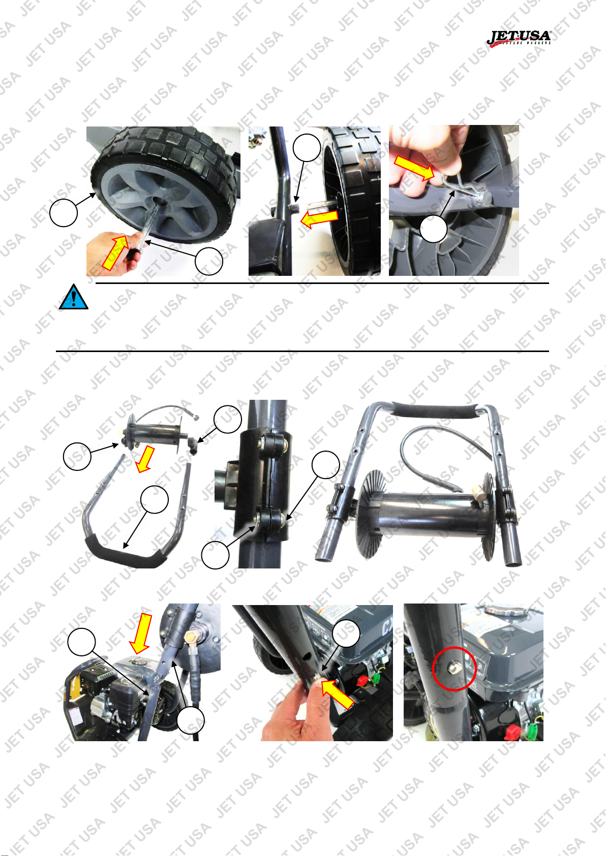
I
J
K
A C D
B
E
F
H G L
M M N
1. Insert the wheel axles (A) into the tubes (B) on the underside rear of the machine frame. Press the
spring-loaded pin (C) in to insert the axle and ensure that it "pops" through the hole in the tube (D).
2. Place a wheel (E) onto each axle, with the long hub (F) toward the frame. Secure each wheel with a M12
washer (G) and nut (H) and tighten (rotate right) with a suitable spanner.
3. Insert the handle (I), with nozzles facing the front of the machine, into the frame tubes (J). Insert an
extension nut (K) through the holes in the frame tubes and handle from the outside and secure on the
inside using an M6 screw (not shown). Tighten (rotate right) the fasteners using the two Allen keys.
4. Attach the lance bracket (L) to the right-hand side of the handle using 2 M5 screws (M), washers and
nuts (not shown). Tighten (rotate right) the fasteners using a suitable spanner and Allen key.
5. Attach the hose bracket (N) to the left-hand side of the handle using 2 M5 screws (M), washers and nuts
(not shown). Tighten (rotate right) the fasteners using a suitable spanner and Allen key.
The machine is now basically assembled. Refer to Pumps, Hoses and Fittings.
E&OE © 2017 Jet-USA 8
Page 9

Petrol Powered Pressure Washers
No.
Name
No.
Name
1
Frame / Engine / Pump / Handle / Nozzles /
Detergent Tank Assembly
7
Fasteners / Tools:
Wheel Axle (2)
"R" Clip (2)
Spark Plug Tool
2
Wheel (2)
3
Lance
4
Lance Extension
5
Pump Outlet Hose
6
Pump Inlet Hose (includes strainer)
1 3 6
7 5 4
2
CX600 - Parts Identification and Assembly
E&OE © 2017 Jet-USA 9
Page 10

Petrol Powered Pressure Washers
A C D B F
E
1. Insert a wheel axle (A) through each wheel (B).
2. Line up the hole (C) in the axle with the hole (E) in the frame axle tube (D), then push the axle into the
tube so holes (C and E) are aligned.
3. Insert a "R" clip (F) through the hole so the axle is secured.
The machine is now basically assembled. Refer to Pumps, Hoses and Fittings.
E&OE © 2017 Jet-USA 10
Page 11

Petrol Powered Pressure Washers
No.
Name
No.
Name
1
Frame / Engine / Pump / Nozzles / Detergent Tank
Assembly
7
Pump Inlet Hose (includes strainer)
2
Wheel (2)
8
Hose Hanger (includes nuts and washers)
3
Handle
9
Detergent Tube (includes strainer)
4
Lance
10
Fasteners / Tools:
Wheel Axle (2)
"R" Clip (2)
Spark Plug Tool
5
Lance Extension
6
Pump Outlet Hose
1 4 7
10 6 5
2 3 8
9
CX630 - Parts Identification and Assembly
E&OE © 2017 Jet-USA 11
Page 12

Petrol Powered Pressure Washers
A C B D E F G
H
1. Insert a wheel axle (A) through each wheel (B).
2. Push each axle into the frame axle tube (C).
3. Insert a "R" clip (D) through the hole in the axle, so the axle is secured.
4. Insert the handle (E) into the frame tubes (F). The handle can be inserted with the hand-hold bend facing
either way. Press the spring-loaded pins (G) in so the handle tube can pass over them. When the pins
"pop" through the holes in the handle, the handle is assembled correctly.
Insert the ends of the hose hanger (H), from the rear of the machine and with the "hooked" section facing up,
through the holes (I) in the handle. Secure the hanger with the nuts and washers. Tighten (rotate right) the
fasteners using a suitable spanner.
The machine is now basically assembled. Refer to Pumps, Hoses and Fittings.
E&OE © 2017 Jet-USA 12
Page 13
Petrol Powered Pressure Washers
No.
Name
No.
Name
1
Frame / Engine / Pump / Detergent Tank
Assembly
12
Detergent Tube (includes strainer)
2
Wheel (2)
13
Fasteners / Fittings / Tools:
Wheel Axle (2)
"R" Clip (2)
M6x50 Screw (4)
M6x15 Screw (4)
M6 Nut (4)
M6 Lock Nut (4)
Drain Clean Nozzle
½" Male to ½" Male Fitting
¼" Male to ¼" Male BSP Fitting
½" Male to ¼" Male Fitting
Spark Plug Tool
Screwdriver
Spanner
3
Handle
4
Lance
5
Lance Extension
6
Curved Lance Extension
7
Pump Outlet Hose
8
Extension Pump Outlet Hose
9
Nozzle Panel
10
Hose Reel / Brackets / Handle / Connection Hose
11
Pump Inlet Hose (includes strainer)
1
11
12
13 4 6
10 6 5
2 3 7
9
CX660 - Parts Identification and Assembly
E&OE © 2017 Jet-USA 13
Page 14
Petrol Powered Pressure Washers
A C B D E J K
F
G
H
I
E
1. Insert a wheel axle (A) through each wheel (B).
2. Push each axle into the frame axle tube (C).
3. Insert a "R" clip (D) through the hole in the axle, so the axle is secured.
The handle can be inserted with the hand-hold bend facing either way. Bear this in mind when you
assemble the hose reel to the handle, as the reel must be mounted so the pump connection
hose is on the left-hand side of the machine. Set out the handle and reel parts before assembling. In the
example images, the handle is being set up so the hand-hold bend is facing the rear of the machine. The
reel can be installed so the pump connection hose fitting and winder sits either in front or behind the handle.
4. Slide the reel brackets (F and G) up the handle (E) tubes approximately 150mm (6"). Secure the
brackets to the handle using 4 M6x15 screws (H) and lock nuts (I) – there are recessed in the brackets
for the nuts. Tighten (rotate right) the screws using the screwdriver.
5. Insert the handle (E) into the frame tubes (J). Press the spring-loaded pins (K) in so the handle tube can
pass over them. When the pins "pop" through the holes in the handle, the handle is assembled correctly.
E&OE © 2017 Jet-USA 14
Page 15

Petrol Powered Pressure Washers
Route pump
outlet hose
UNDER
engine on
left-hand side
Connect
hose to
pump outlet
Cabletie hose
to frame
Hose Routing – CX660 Only
The pump outlet hose to the hose reel must be routed as described below. This is to prevent it being
exposed to excessive engine exhaust heat that may cause damage to the hose.
1. During assembly, ensure that the hose reel is mounted with the handle on the right-hand side and the
pump hose on the left-side of the machine (when standing behind the machine and looking forward).
2. Route the pump-to-reel hose UNDER the engine, then connect it to the pump outlet.
3. Secure the hose with cable ties to the machine frame, then trim off excess cable-tie.
Tip: For a video tutorial regarding pump outlet hose routing, see
https://youtu.be/Cc8e8Y-mYwM or scan the "QR code".
The machine is now basically assembled. Refer to Pumps, Hoses and Fittings.
E&OE © 2017 Jet-USA 15
Page 16

Petrol Powered Pressure Washers
No.
Name
No.
Name
1
Frame / Engine / Pump Assembly
10
Fasteners / Fittings / Tools:
M5x30 Screw (4)
M5x35 Screw (2)
M5 Nut (6)
M5 Washer (12)
Inlet Hose Adaptor
Screwdriver
Spark Plug Tool
Spare O-rings and Inlet Strainer (may be included)
2
Lance
3
Lance Extension
4
Lance Bracket
5
Hose Bracket
6
Detergent Bottle Bracket
7
Pump Outlet Hose
8
Detergent Bottle Holder
9
Detergent Bottle and Tube
1 2 5
10
6 9 4 3 7
8
MX400 – Parts Identification and Assembly
E&OE © 2017 Jet-USA 16
Page 17

Petrol Powered Pressure Washers
A C D
B E F
H
C D G
C D G
I
1. Attach the detergent bottle bracket (A), with the hook facing up, to the front right of the machine frame
and secure using 2 M5x35 screws (B), 4 washers (C) and 2 nuts (D). Tighten (rotate right) the fasteners
using a suitable screwdriver and spanner. Slide the detergent bottle holder (E) on to the detergent bottle
bracket.
2. Attach the lance bracket (F) to the front left of the machine frame and secure using 2 M5x30 screws (G),
4 washers (C) and 2 nuts (D). Tighten (rotate right) the fasteners using a suitable screwdriver and
spanner.
3. Attach the hose bracket (H) to the front left side of the machine frame and secure using 2 M5x30 screws
(G), 4 washers (C) and 2 nuts (D). Tighten (rotate right) the fasteners using a suitable screwdriver and
spanner.
4. Slide the detergent bottle (I) into the holder.
The machine is now basically assembled. Refer to Pumps, Hoses and
Fittings for hose assembly information.
E&OE © 2017 Jet-USA 17
Page 18

Petrol Powered Pressure Washers
No.
Name
No.
Name
1
Frame / Engine / Pump Assembly
10
Fasteners / Fittings / Tools:
Wheel Axle (4)
M12 Nut (4)
Pump Vent Cap / Dipstick
Barbed Inlet Connector
"Turbo" Nozzle Adaptor (may come preassembled)
Spark Plug Tool
2
Wheel (4)
3
Lance
4
Lance Extension
5
Lance / Hose Bracket
6
"Turbo" Nozzle (may be included, and adaptor
may be pre-assembled)
7
Pump Outlet Hose
8
Pump Inlet Hose (includes strainer)
9
Detergent Tube (includes strainer)
1 2 5
10
6
9 4 3 7 8
TX870 - Parts Identification and Assembly
E&OE © 2017 Jet-USA 18
Page 19

Petrol Powered Pressure Washers
A
C
D B E
F G H
1. Insert the wheel axles (A) into the tubes (B) on the underside rear of the machine frame. Press the
spring-loaded pin (C) in to insert the axle and ensure that it "pops" through the hole in the tube (D).
2. Place a wheel (E) onto each axle, with the long hub (F) toward the frame. Secure each wheel with a M12
nut (G) and tighten (rotate right) with a suitable spanner.
3. Attach the lance / hose bracket (H) to the top right-hand side of the machine frame by inserting the legs
of the bracket through the holes in the frame and securing using 2 nuts (not shown). Tighten (rotate
right) the nuts using a suitable spanner.
The machine is now basically assembled. Refer to Pumps, Hoses and Fittings for hose assembly
information.
E&OE © 2017 Jet-USA 19
Page 20

Petrol Powered Pressure Washers
No.
Name
No.
Name
1
Pump Inlet
4
Pressure Release Valve
2
Pump Outlet
5
Output Pressure Adjustment Valve
3
Detergent Port
1
5 1 3
4
2 2 3
4 5 4 1 2
3
Pumps, Hoses and Fittings
The machine comes supplied with pump and components necessary for normal use. Some machines may
include extra or optional lance attachments, nozzles, extension hoses etc. The basic methods for connecting
hoses and using various fittings remains the same. Some information below may or may not apply explicitly
to your machine.
Pumps
The pump output pressure is set at the factory. There is no need to alter the output
pressure adjustment valve unless the pump includes a specific adjuster. Altering the
output pressure may damage the machine and void the product warranty.
There are two main pump types. Visually confirm which type of pump your machine has.
Sealed
The pumps are manufactured in a way that requires no maintenance. The pumps are oil-filled during
production and do not require breather caps, oil changes or have an oil sight glass or oil filler. Pump
appearance and features are:
E&OE © 2017 Jet-USA 20
Page 21

Petrol Powered Pressure Washers
No.
Name
No.
Name
1
Pump Inlet
5
Oil Level Sight Glass
2
Pump Outlet
6
Oil Drain Plug
3
Detergent Port
7
Output Pressure Valve – limited adjustment
4
Oil Filler / Breather Cap
7 2 4
1 6 5
3
Type A
Type B
Type C
Type D
7
Non-Sealed
The pumps are manufactured in a way that requires normal pump maintenance. The pumps are usually oilfilled during production, require a breather cap, pump oil changes and have an oil sight glass and/or dipstick,
oil drain and oil filler.
Hoses and Fittings
The machine comes with necessary hoses and fittings. The length, number of hoses and nozzles or
accessories may vary depending on model. Some parts, such as the "turbo head" may come pre-assembled.
It is recommended to use plumbers Teflon tape (not supplied) on all threaded
hose connections. To apply the tape, wrap it around the male thread of the
fitting several times – 5 wraps is generally sufficient. When wrapping, rotate the tape to
the right (clockwise) around the thread so it does not get unravelled when screwing the
connection in. • The thread type on some connectors may vary slightly – always check
the compatibility of the connectors before applying plumbers tape and making the final
connection. • Always tighten connections using suitable spanners (where applicable)
and ensure that the connections are secure.
The possible fittings are shown below. Not all models will come with all fittings.
• Type A – Used to connect an extension hose to the end of the lance.
• Type B – Used to connect an extension hose to the end of the standard hose.
• Type C – Used to connect the drain cleaning fitting to the end of a hose.
• Type D – Drain cleaning fitting – connects to a Type C fitting.
E&OE © 2017 Jet-USA 21
Page 22

Petrol Powered Pressure Washers
Item
Description
Item
Description
A
Standard Hose
F Extension Hose
B
Lance G
Type B Fitting
C
Lance Extension
H Type A Fitting
D
Nozzle I
Type C Fitting
E
"Turbo Head"
J Type D "Drain Cleaner" Fitting
1 2 3
The following image shows the possible combinations of hoses, fittings and nozzles.
Turbo-Head Assembly
If the "turbo head" and turbo-head is not assembled, 1) wrap the threaded part of the turbo-head adaptor
fitting with plumbers Teflon tape (not supplied), then 2) screw the adaptor into the turbo-head, then 3) use an
Allen key through the adaptor to tighten it firmly to the turbo-head.
Using Connectors
The connector used can be any of 3 types – screw type fittings as previously described, threaded collar type
fittings and "quick-connect types". The type of connectors supplied may vary.
Threaded Collar Type Connectors
1. Ensure the O-ring is correctly fitted and undamaged and that the
connectors are clean.
2. Insert the male connector into the female and when the threads engage,
firmly tighten (rotate right / clockwise) the collar by hand.
E&OE © 2017 Jet-USA 22
Page 23

Petrol Powered Pressure Washers
"Quick-Connect" Type Connectors
1. Ensure the connectors are clean.
2. Pull back on the knurled ring until the ball bearings are visible and hold it in this position, then insert the
male connector into the female. When the parts are fully connected, release the knurled ring.
Nozzles
The machine may come supplied with a variety of nozzles. Each nozzle is colour-coded for identification and
produces a different spray pattern for different tasks. Nozzle colours may vary – check each before use.
• Red – 0° spread. Highest possible pressure for difficult cleaning tasks
including stained concrete and paint removal. Not recommended for soft
materials, decking or automotive.
• Yellow – 15° spread. Very high pressure for heavy cleaning tasks including,
concrete, decking and paint removal. Not recommended for soft materials or
automotive.
• Green – 25° spread. High pressure for general cleaning tasks including
automotive.
• White – 40° spread. Moderate pressure for general cleaning larger surfaces.
• Black – 65° spread. Low pressure for general cleaning larger surfaces and when using detergent.
• "Turbo-Head" – High pressure cleaning larger surfaces. The design of the turbo-head provides a
"swirling" action to the spray that makes it a versatile general-purpose cleaning nozzle.
Nozzle Cleaning
Do NOT clean a nozzle whilst it is attached to the machine. Ensure that the engine is OFF
and the water supply is OFF before detaching a nozzle. • Use caution when cleaning a
nozzle to prevent damaging the nozzle orifice.
The machine may come with a nozzle cleaning wire which can be used if a nozzle becomes blocked.
Remove the nozzle from the machine and carefully insert the end of the wire into the nozzle hole to clear it.
E&OE © 2017 Jet-USA 23
Page 24

Petrol Powered Pressure Washers
Route
detergent tube
around righthand side
Detergent System
Do NOT use chlorine, bleach, tri-sodium phosphate, ammonia, acid-based, caustic, or
corrosive substances in the detergent system as these will damage the machine and may
damage the surface being cleaned. Use liquid car wash or similar mild detergents only. Use of non-
recommended substances in the detergent system will void the product warranty. • The use of
detergent requires the correct low-pressure nozzle to be used.
Some machines may be equipped with a detergent tank. Other types may have a detergent port on the
pump, however, require a separate container (not supplied) for the detergent. The "vacuum" created by
water flow through the pump enables the detergent to be drawn into the outlet flow. Some models may have
a detergent flow control on the detergent cap – rotate the cap as required.
Assembly – CX630 and CX660
Minor assembly is required for the detergent system. The unit comes with the detergent tank cap
and tube removed – it must be installed before use.
1. Insert the filter end of the detergent pickup tube through the filler and into the detergent tank.
2. Place the detergent tank cap onto the filler, with the arrow in the "12-o'clock" position.
3. Push the cap firmly against the filler, then rotate it right until the cap locks and the arrow is approximately
in the "2-o'clock" position.
4. Route the detergent output tube from the cap around the right-hand side of the machine (when standing
behind the machine and looking forward).
5. Push the pump end of the detergent output tube to the detergent port on the top of the pump.
E&OE © 2017 Jet-USA 24
Page 25

Petrol Powered Pressure Washers
No.
Name
No.
Name
1
Exhaust
7
Oil Filler/Dipstick (some models have 2)
2
Fuel Tank (fuel filler on top)
8
Oil Drain Plug (some models have 2)
3
Air Intake Assembly (filter inside)
9
Engine ON/OFF Switch
4
Choke
10
Starter Cord
5
Throttle
11
Spark plug (not visible)
6
Fuel Tap
12
Output Shaft (pump removed)
1 3 2 7 8 9 4 5 6
10
12
11
Engines – Parts Identification
It is strongly recommended that you familiarise yourself with all major components of the machine before
using it or performing any maintenance tasks.
Products detailed in this manual may vary in appearance, inclusions, description and packaging
from those shown or described. This section shows typical major components common to most
engines.
E&OE © 2017 Jet-USA 25
Page 26

Petrol Powered Pressure Washers
Before Use Checklist
Ensure that you carry out all procedures below before starting the engine or operating the
equipment. All procedures described are generic in nature and slight variations between
different models may exist. Failure to follow the checklist and carry out the procedures
correctly may result in making the product warranty void. The product is NOT supplied with engine oil,
although traces of oil from the manufacturing process may be present. It is essential to add adequate engine
oil of the correct type to the engine before use – see Checking and Changing Engine Oil. Failure to add
engine oil will void the product warranty.
Engine Oil
Four-stroke engines require engine oil in the crankcase for lubrication of internal components. Severe or
irreparable damage may occur if the engine is allowed to run without engine oil. The engine oil level requires
regular maintenance. Check the engine oil level and ensure that the oil level is at or just under the maximum
level indicator.
Always check the engine oil level before starting the engine. See Checking and Changing Engine Oil.
Air Filter
The air filter is used to prevent dirt and other particles from possibly entering the engine and causing internal
damage to it. The air filter requires regular maintenance.
Always check the air filter before starting the engine. See Checking, Cleaning and Replacing the Air Filter.
Fuel
Petrol/fuel/gasoline is extremely flammable – keep clear of naked flames or other ignition
sources. • The engine must be cool before refuelling.
Adequately fill the fuel tank with the correct fuel type.
• Use non-ethanol unleaded petrol (higher RON values will provide best engine performance). Do not use
old or contaminated fuel.
To fill or top up fuel:
1. Place the machine in an upright position on a flat and level surface.
2. Clean the machine around the fuel filler so that no dirt or other material enters the engine when the cap
is removed.
3. Remove (rotate left) the fuel filler cap.
4. Using a funnel, carefully fill the tank with fuel. Do not fill above the top of the strainer (if equipped) or
otherwise overfill the tank.
5. When finished, reinstall (rotate right) the fuel filler cap until firm. Wipe away any residual fuel from the
machine. If fuel has been spilt, move the pump away from the spillage before starting the engine.
Pump Oil – Non-Sealed Pumps Only
Water pumps require oil for lubrication of internal components. Severe or irreparable damage may occur if
the pump is used without oil. The pump oil for non-sealed pumps requires regular maintenance, however,
does come shipped with oil. Check the oil level and ensure that it is at or just under the maximum level
indicator.
Always check the pump oil level before starting the engine. See Checking and Changing Pump Oil.
E&OE © 2017 Jet-USA 26
Page 27

Petrol Powered Pressure Washers
A
B
Pump Breather – Non-Sealed Pumps Only
Do NOT operate the machine until the shipping plug has been removed and the vent / breather cap
is installed. Failure to do so may result in machine damage and will void product warranty.
For pumps that are not a "sealed unit" type there is a shipping plug on the pump that is used to prevent
pump oil (pre-filled at the factory) leaking during shipping. The shipping plug MUST be removed and
swapped for the vent / breather cap before using the machine.
1. Place the machine in an upright position on a flat and level surface.
2. Clean the machine around the shipping plug (A) so that no dirt or other material enters the pump when
the cap is removed.
3. Remove (rotate left) the shipping plug.
4. Ensure that the vent / breather cap is clean.
5. Insert the vent / breather cap (B) to the pump and firmly tighten (rotate right) by hand.
Connecting High-Pressure Hoses
Use the high-pressure hoses and connectors / fittings supplied with the unit ONLY. •
Ensure that all hoses and connectors / fittings are correctly installed and secure.
1. Assemble the high-pressure hoses, lance and fittings into the required configuration.
2. Attach a nozzle to the end of the lance extension.
3. Connect the free end of the high-pressure hose to the pump outlet connector. Some models may provide
a threaded collar or "quick-connect" fitting. Ensure that threaded types are firmly tightened.
E&OE © 2017 Jet-USA 27
Page 28

Petrol Powered Pressure Washers
Connecting the Water Supply
The machine must be connected to a water supply that can deliver sufficient water for pumping. Most
domestic applications will use a standard garden hose connected to the mains water supply. In cases where
no mains or gravity fed water supply is available, the machine can draw water from a suitable reservoir using
the supplied inlet hose and strainer.
When using a garden hose and mains water supply, it is recommended to run water through the
hose first to flush out any debris BEFORE connecting it to the pump inlet. • Do NOT use hot water
or water at temperatures above 40°C (104°F) as damage to the pump may result. Using hot water in the
machine may void the product warranty.
Mains Water Supply
1. Connect a standard garden hose to the water supply and
the pump inlet connector. Ensure that the connections are
secure.
2. Turn ON the water supply.
3. Squeeze the trigger on the lance. When a steady stream
of water is flowing from the nozzle, the machine is ready to
be used.
Using the Machine to Draw Water
The maximum length of the inlet hose is 5m (15'). Do NOT exceed this limit. • Do NOT use the inlet
hose without the strainer attached. • Do NOT allow the strainer end of the inlet hose to rest at the
bottom of the reservoir as it may allow contaminants into the pump. • When running the engine to suck water
into the pump, do NOT allow it to run for more than 60 seconds. • The pump suction procedure will require
repeating if the machine is switched OFF and / or air gets into the inlet hose. Running the pump "dry" for
longer than 60 seconds may permanently damage it and will void the product warranty.
1. Connect the supplied inlet hose to the pump inlet connector.
2. Place the free end of the inlet hose into the water reservoir.
3. Start the machine engine and run it at approximately half throttle. The pump will begin sucking in water.
4. Squeeze the trigger on the lance. When a steady stream of water is flowing from the nozzle, the machine
is ready to be used.
E&OE © 2017 Jet-USA 28
Page 29

Petrol Powered Pressure Washers
C
A D B
E
Video Tutorial:
Starting 4-Stroke Engines
Engine Starting
Before starting the engine, ensure that you have
followed all procedures described in the Before Use Checklist. The product is NOT supplied
with engine oil, although traces of oil from the manufacturing process may be present. It is essential to add
adequate engine oil of the correct type to the engine before use – see Checking and Changing Engine Oil.
Failure to add engine oil will void the product warranty. • Always wear suitable protective clothing and
equipment when using the machine. • Inspect the machine before each use and check for wear or damage.
If the machine is damaged, have it inspected and repaired at an authorized service centre before using it
again.
Different models may feature variations in design; for example, some have different engine types etc. The
following procedures and images are typical to all models, however, the position or appearance of controls
etc may vary. All major engine controls are identified on the machine by way of stickers or other markings.
Manual/Pull Starting
1. FUEL – Place the fuel tap (A) in the "ON" position.
2. CHOKE – If the engine is cold, place the choke (B) in
the "COLD" or "CLOSED" position. If the engine is
warm or the ambient temperature is high, place the
choke in the “RUN” or “OPEN” position.
3. IGNITION – Place the engine ON/OFF switch (C) in the
"ON" ("I") position.
4. THROTTLE – Place the throttle control (D) just off the
"SLOW" position.
5. START – Slowly pull out the starter cord (E) until you
feel it engage with the engine, then pull it out rapidly (use both hands if
necessary). The engine should start. Allow the starter cord to rewind slowly – do
not let it "snap" back.
6. WARM-UP – Allow the engine to warm-up and run smoothly. If choke is being
applied, place the choke (B) in the "RUN" or "OPEN" position.
7. THROTTLE – Adjust the throttle control (D) for the required engine speed and
pumping requirements.
If the engine does not start, repeat step 5 onward. If the engine fails to start after several attempts, refer to
Troubleshooting.
Stopping the Engine
Stopping in an Emergency
1. To stop the engine immediately, place the engine ON/OFF switch in the "OFF" position.
Stopping in Normal Use
1. Place the throttle control in the "SLOW" position.
2. Place the engine ON/OFF switch or key switch in the "OFF" position.
3. Place the fuel tap in the "OFF" position.
E&OE © 2017 Jet-USA 29
Page 30

Petrol Powered Pressure Washers
Environmental Considerations
Altitude
If the engine is being used in altitudes at or above 1500m (approximately 5000’), adjustments to the
carburettor may be required. This is because there is less oxygen in the air as altitude increases, which
effectively "enriches" the ratio of fuel to air going into the engine and the higher the altitude, the richer the
fuel mixture becomes. If the engine is being permanently operated at high altitude, it is recommended to
have an authorized service centre make the necessary carburettor adjustments. If the engine is used
occasionally at altitude (not extreme altitudes), no adjustments should be required, however, a slight
decrease in engine performance can be expected.
Temperature
If the engine is being used in extremely cold or hot
environments; for example, desert or snow conditions, the type
of engine oil may need to be changed to suit environmental
temperatures. Oil thickens as the temperature decreases and
thins as temperature increases, which means that if the engine
oil is not suited to the temperature its ability to properly lubricate
the engine may be affected. Use the following chart to determine
the correct engine oil:
E&OE © 2017 Jet-USA 30
Page 31

Petrol Powered Pressure Washers
A
B
Pressure Washer Operation
Use the high-pressure hoses and connectors / fittings supplied with the unit ONLY. • Ensure
that all hoses and connectors / fittings are correctly installed and secure. • Always hold the
lance with both hands to avoid recoil. • Do NOT use the machine whilst standing on a ladder. • Water may
flow from the pump pressure release valve (if fitted) when the engine is running but the spray action of the
machine is not being used – this is to protect the pump and is normal. • If the engine is running but the spray
action of the machine is not to be used for more than 2 minutes, switch the engine OFF. Leaving the
machine running without spraying for extended periods may damage the pump and / or other
components and will void the product warranty. • Highest effective water pressure occurs when the lance
trigger is first pulled. The pressure washer creates very high pressures that can puncture skin, cause severe
injury and/or poison blood. Do not direct the high-pressure spray at any person, animal, electrical equipment,
equipment or items that can be damaged by high-pressure water spray or the machine itself. • Do not allow
any persons, animals etc to be within 20m (60') of the equipment when in use. • Do not operate the machine
without a liquid source to draw in.
Be aware that once the engine is running, the pumping action of the machine activates. When the engine is
idling (slowest continuous running speed), the output water pressure is minimal. As you increase engine
speed (use the engine throttle control), the water pressure increases. Note the following recommendations:
• Operate the engine at a sufficient speed to provide the desired output pressure.
• Use the correct nozzle for the job. Nozzles that concentrate the water jet into a small area can gouge
and damage some surface materials.
• Before commencing the job, pressure clean a small test area to ensure that the surface will not be
damaged and the machine will clean the surface adequately.
• Uncoil the high-pressure hose(s) fully before using the machine.
• Use a sweeping and overlapping pattern to help ensure effective cleaning and coverage.
• When cleaning using detergents, always rinse off any residues afterward.
1. Assemble the high-pressure hoses, lance and fittings into the required configuration.
2. Attach a nozzle to the end of the lance extension.
3. Connect the high-pressure hose to the pump outlet connector.
4. Connect the machine to the water supply and turn the water supply ON.
5. Squeeze the lance trigger and allow any air in the hoses and pump to be ejected by the water supply
pressure. The water should flow freely before starting the engine.
6. Start the engine.
Using the Lance
The lance has a "trigger" (A) to start and stop spraying. The lance may feature a "lock" (B) that prevents the
trigger accidentally being pulled. To spray, release the lock (if fitted or engaged) and pull the trigger – the
spray action will continue while the trigger remains pulled. Release the trigger to stop the spray action.
E&OE © 2017 Jet-USA 31
Page 32

Petrol Powered Pressure Washers
Frequency – Whichever Comes First
Component/Task
Every Use
First Month or
20 Hours Use
Every 3 Months
or 50 Hours Use
Every 6 Months or
100 Hours Use
Every Year or
300 Hours Use
Engine Oil
Check
Replace
Replace
Oil Leaks
Check/repair as
necessary
Air Cleaner
Check
Clean and replace as necessary
Spark Plug
Check
Replace
Valve Clearance
Adjust as
necessary
Combustion
Chamber
De-coke as
necessary
Idle Speed
Check/adjust as
necessary
Fasteners
Check/tighten
as necessary
Fuel Tank
Flush and clean
Fuel Line
Replace as necessary
Fuel Filter
Clean and replace as necessary
Fuel Strainer
Check
* Pump Oil
Check
Replace
Maintenance
Running combustion engines in confined areas CAN KILL IN MINUTES. Engine
exhaust fumes contain carbon-monoxide – a deadly gas that you cannot smell or
see. NEVER run a combustion engine in confined areas EVEN IF windows and doors are open. ONLY run
combustion engines OUTDOORS and away from doors, windows and vents. • Petrol/fuel/gasoline is
extremely flammable – keep clear of naked flames or other ignition sources. • Do not have the engine
running during inspection and maintenance unless specifically required. • The engine should be cool enough
to touch before performing maintenance activities. • Ensure that the water supply is OFF and disconnected
from the machine and that all pressure has been released before performing any maintenance tasks. • Some
maintenance activities described may be beyond the scope of some users. For procedures that you are not
comfortable with or have the tools or experience for, have the unit serviced by a service centre or qualified
technician. • There may be slight variations between models to the images shown and the procedures
described here.
To keep the machine performing at optimal efficiency, regular checks and maintenance is required. Proper
care and maintenance ensures best performance and longest service life.
The maintenance schedule below specifies preventative maintenance checks and necessary maintenance
tasks and how often they should be performed. The schedule applies to multiple engines; some engines may
not include some components, so maintenance on those components is not applicable.
Harsh operating environments such as extreme temperatures, dust etc may necessitate more
frequent maintenance. • Maintenance frequencies are based on general factors including a
maximum use of approximately 300 hours per year. Apply common-sense when following the maintenance
schedule based on your actual use of the product. • Keep reasonable records of maintenance activities for
reference. Failure to follow the maintenance schedule, using incorrect or non-compatible accessories
or replacements parts, or general negligence may result in making the product warranty void.
Maintenance Schedule
* Models with non-sealed pumps only.
E&OE © 2017 Jet-USA 32
Page 33

Petrol Powered Pressure Washers
A B C D D
Checking and Changing Engine Oil
The product is NOT supplied with engine oil, although traces of oil from the manufacturing
process may be present. It is essential to add adequate engine oil of the correct type to the
engine before use. Failure to add engine oil will void the product warranty. • Always check engine oil
level when the machine is in an upright position on a flat and level surface. • Do not use used or
contaminated engine oils. • Use only engine oils of the correct type (see Specifications). • Perform the first oil
change within the first 20 hours of use. Subsequently, change the oil every 20 hours of use. • It is
recommended that the engine be warm, but not hot, when performing oil changes. When the oil is warm it
drains faster. • Using dirty or incorrect engine oil may cause engine damage and void any warranty. •
Always use suitable tools. • Always dispose of used oil in an environmentally responsible manner and
according to regulations. • Some engines feature oil level detection, which will prevent the engine being
started or automatically stop a running engine if there is insufficient oil. • Always check the oil level and
ensure is at or near the "MAX" indicator before using the machine. • Some models may have 2 oil drain
plugs and fillers on either side of the engine – it does not matter which one is used.
Four-stroke engines require engine oil in the crankcase for lubrication of internal components. Severe or
irreparable damage may occur if the engine is allowed to run without engine oil. The engine oil level requires
regular maintenance as per the maintenance schedule.
To check engine oil level:
1. Place the machine in an upright position on a flat and level surface.
2. Clean the machine around the oil filler cap (A) so that no dirt or other material enters the engine when
the cap is removed.
3. Remove the oil filler cap (rotate left) until fully unscrewed. For machines without a dipstick, the oil level is
determined by how close the oil is to the edge of the filler hole (B). For machines equipped with an oil
level dipstick:
a. Remove the dipstick (C) and wipe clean with a piece of cloth or paper.
b. Insert the dipstick into the oil filler but do not screw it in.
c. Remove and inspect the dipstick – the oil level is determined by where oil can be seen on it.
4. Ensure that the oil level is at or just under the "maximum". If the oil level is low, add additional oil until the
correct level is reached. If the oil level is too high, drain some oil until the correct level is reached.
5. When finished, re-install (rotate right) the oil filler cap until firm. Wipe off any residual oil from the
machine.
E&OE © 2017 Jet-USA 33
Page 34

Petrol Powered Pressure Washers
To change the engine oil:
1. Place the machine on a suitable work surface that is flat and level and have a container ready to catch
drained oil.
2. Clean the machine around the oil drain plug (D) and oil filler cap/dipstick so that no dirt or other material
enters the engine when the plug or cap is removed.
3. Unscrew (rotate left) and remove the drain plug and washer.
4. Tilt the machine and drain all oil from the engine. Once drained, allow the machine to sit level again.
5. Clean the drain plug and washer and then reinstall them. Screw in fully (rotate right) and firmly tighten.
6. Remove the oil filler cap (rotate left) until fully unscrewed. Wipe the oil level indicator clean with a piece
of cloth or paper.
7. Using a funnel, carefully add oil to the engine until the "maximum" level is reached. Double- check the oil
level (described above).
8. When finished, re-install (rotate right) the oil filler cap until firm. Wipe off any residual oil from the
machine.
E&OE © 2017 Jet-USA 34
Page 35
Petrol Powered Pressure Washers
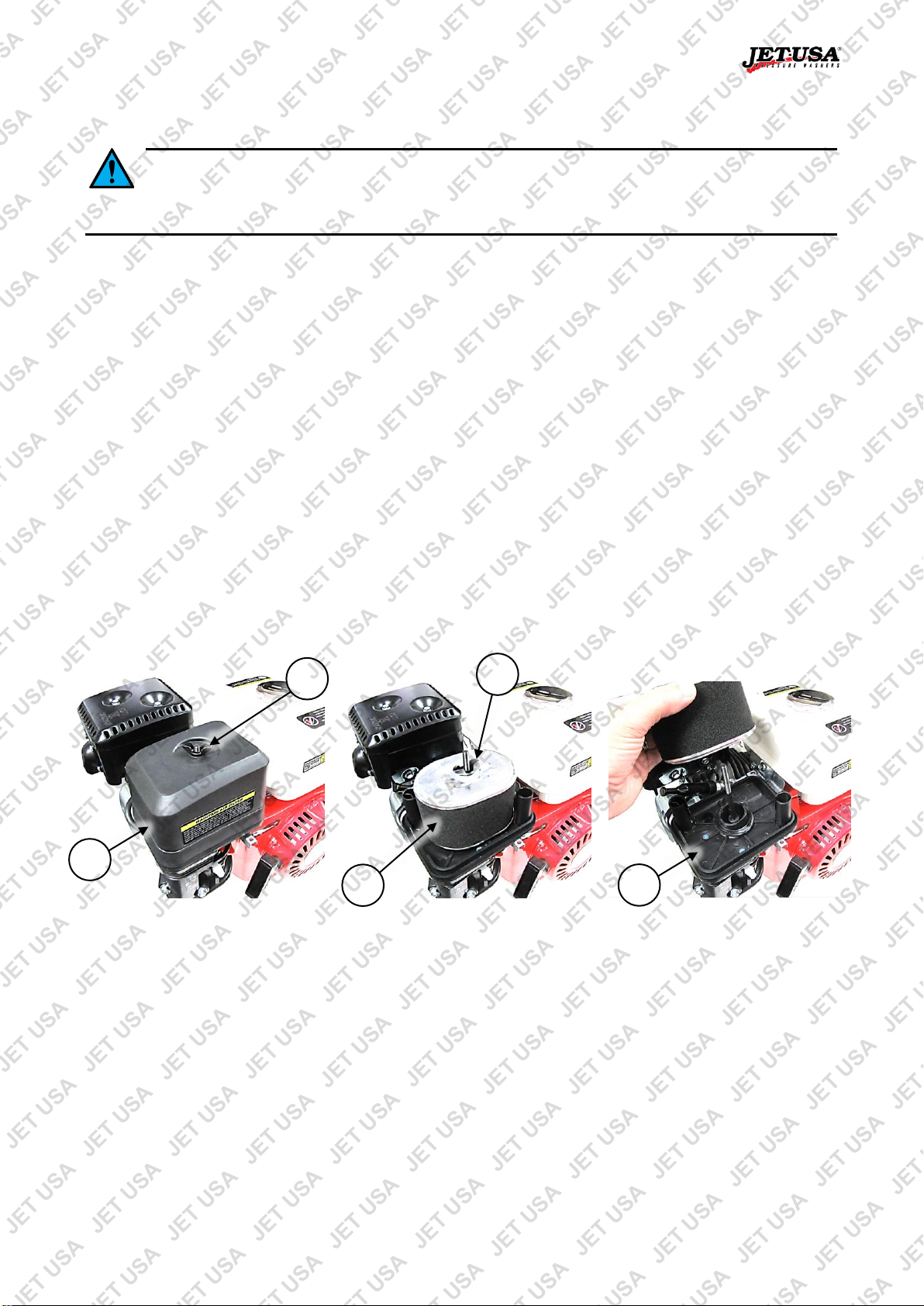
C
B
A
D
E
Checking, Cleaning or Replacing the Air Filter
Operating the machine without a functional air filter may cause severe engine damage and will void
any warranty. • A dirty or oil saturated air filter will restrict air flow, which can be mistaken as fuel
system problems. Check the condition of the air filter before adjusting engine idle speed, where applicable. •
If the air filter is damaged (torn, broken, disintegrating), replace it.
The air filter is used to prevent dirt and other particles from possibly entering the engine and causing internal
damage to it. The air filter requires regular maintenance as per the maintenance schedule.
Air Filter Inspection and Cleaning
Inspect the air filter for dirtiness and debris, damage etc. Clean or replace the filter element as necessary. To
clean air filters:
• For foam filters, wash the filter in warm water and mild detergent, then rinse and allow to dry.
• For paper filters, use compressed air to blow particles from it. The air should be blown from the engine
side of the filter.
• Clean all other air filter assembly components using water and mild detergent, then dry them.
• For foam filters, place a few drops of clean engine oil on the filter then squeeze it a few times to spread
the oil through the filter material and remove any excess oil.
Air Filter Removal/Installation
To remove the air filter:
1. Unscrew (rotate left) the wing nut (B) securing the air filter cover (C) and remove the cover from the air
intake assembly (A).
2. Unscrew (rotate left) the wing nut (D) and remove the filter element (E).
To install the air filter:
1. Re-install the filter element and ensure it is seated correctly on the air intake assembly.
2. Re-install (rotate right) the wing nut and tighten by hand so that the filter element is secure. Do not over-
tighten.
3. Re-install the filter cover and secure it with the wing nut (rotate right). Tighten the nut by hand. Do not
over-tighten.
E&OE © 2017 Jet-USA 35
Page 36

Petrol Powered Pressure Washers
A
B
B X A
B
A
C
Spark Plug
If the spark plug is damaged (cracked insulator, broken or eroded electrodes etc), replace it. •
Always use spark plugs of the correct "heat range" - see Specifications.
The spark plug is used to ignite the air/fuel mixture inside the engine. The spark plug has electrodes on one
end and an electrical terminal on the other. The spark plug requires regular maintenance.
Spark Plug Cleaning and Gap Checking
The spark plug should be checked and cleaned as per the maintenance schedule.
1. Remove any carbon deposits on the spark plug (A) electrodes (B) with a wire
brush.
2. Clean the spark plug threads and the electrical terminal (C) on the top.
To check and adjust the spark plug "gap":
1. Use "feeler" or "thickness" gauges (X) to measure the existing gap. The gauge
must drag a little when being slid between the electrodes (2) – this means the
measurement is fairly accurate.
2. Adjust the gap to within specification (see Specifications). If the gap needs to be
reduced, gently tap the electrode as required. If the gap needs to be increased,
use pliers to gently pull the electrode as required.
3. Measure the gap again and ensure it is within the specified range before re-installing the spark plug.
Spark Plug Removal/Installation
1. Pull the electrical lead (B) from the terminal on top of the spark plug (A).
2. Clean the area around the spark plug so that no dirt or other material can enter the engine when the
spark plug is removed.
3. Use the spark plug tool (C) to remove the spark plug (rotate left).
To re-install the spark plug:
1. Place the spark plug in its hole and screw it in (rotate right) until "finger tight".
2. Use the spark plug tool to tighten the spark plug approximately one quarter turn (do not over-tighten).
3. Place the electrical lead over the spark plug terminal and push it down so that it connects firmly with the
terminal
E&OE © 2017 Jet-USA 36
Page 37

Petrol Powered Pressure Washers
B
A
C
Checking and Changing Pump Oil – Non-Sealed Pumps Only
For machine that have unsealed pumps, it is necessary to maintain the pump oil. Sealed pumps do
not feature oil drains and fillers. Any attempt to service or alter a sealed pump may damage it
and void product warranty. • Suitable pump oils are 80W-90 / 85W-90 / SAE 90. Using dirty or incorrect
oil in the pump may damage it and void product warranty. • Always use suitable tools. • Always dispose
of used oil in an environmentally responsible manner and according to regulations. • Always check the oil
level and ensure is at or near the "MAX" indicator before using the machine. • Some models may have
2 oil level sight glasses – it does not matter which one is used
Water pumps require oil for lubrication of internal components. Severe or irreparable damage may occur if
the pump is used without oil. The pump oil for non-sealed pumps requires regular maintenance. The pump
oil requires regular maintenance as per the maintenance schedule.
To check pump oil level:
1. Place the machine in an upright position on a flat and level
surface.
2. View the current pump oil level through the oil sight glass (A).
Do not use the dipstick for checking oil level as the function is
more as a filler and breather cap than oil level gauge. The
centre of the sight glass is the indicator – the oil level should
be near the centre of the sight glass.
3. Ensure that the oil level is at or just under the "maximum". If
the oil level is low, add additional oil through the filler until the
correct level is reached - clean the machine around the oil
filler cap (B) so that no dirt or other material enters the pump
when the cap is removed, then remove the oil filler cap
(rotate left) until fully unscrewed. If the oil level is too high,
drain some oil until the correct level is reached.
4. When finished, re-install (rotate right) the oil filler cap until firm. Wipe off any residual oil from the
machine.
To change the pump oil:
1. Place the machine on a suitable work surface that is flat and level and have a container ready to catch
drained oil.
2. Clean the machine around the oil drain plug (C) and oil filler cap/dipstick so that no dirt or other material
enters the pump when the plug or cap is removed.
3. Unscrew (rotate left) and remove the drain plug and washer.
4. Tilt the machine and drain all oil from the pump. Once drained, allow the machine to sit level again.
5. Clean the drain plug and washer and then re-install them. Screw in fully (rotate right) and firmly tighten.
6. Remove the oil filler cap (rotate left) until fully unscrewed.
7. Using a funnel, carefully add oil to the pump until the "maximum" level is reached. Double- check the oil
level (described above).
8. When finished, re-install (rotate right) the oil filler cap until firm. Wipe off any residual oil from the
machine.
E&OE © 2017 Jet-USA 37
Page 38

Petrol Powered Pressure Washers
A B C D E
Checking, Cleaning or Replacing Water Inlet and Detergent
Strainers
Some machines may be fitted with water inlet strainers and/or detergent tube strainers. Dirty or
blocked strainers may restrict water or detergent flow, which can reduce performance and be
mistaken as other problems. Check the condition of any strainers before investigating for other faults, where
applicable. • If the strainer is no longer serviceable, replace it.
The strainers are used to prevent dirt and other particles from possibly entering the pump and causing
internal damage to it. The water inlet and detergent strainers (if fitted) require regular maintenance as per the
maintenance schedule.
Strainer Inspection and Cleaning
Inspect the water strainer for dirtiness and debris etc. Clean or replace the strainer as necessary. To clean
water strainers:
• Wash the strainer in clean water.
• If possible, use compressed air to assist in removing any blockages. For detergent strainers, blow air
into the strainer from where it connects to the tube.
Strainer Removal/Installation
To remove strainers:
1. Place the machine in a horizontal position on a flat and level surface.
2. For the water inlet strainer, remove (rotate left) the water inlet adaptor (A) from the pump inlet connector
(B).
3. Pull the water strainer (C) from the inside of the pump inlet connector.
4. For the detergent strainer, remove the detergent tank cap, then pull the detergent intake tube (D) from
the tank.
5. The detergent strainer (E) is installed on the end of the tube – to remove it, twist and pull it from the end
of the tube
To install strainers:
1. For the water inlet strainer, place it back into the pump water inlet connector. Ensure that you install it
with the conical section the same direction as it was removed.
2. Re-install (rotate right) the water inlet adaptor.
3. For the detergent strainer, firmly push the strainer onto the detergent intake tube.
4. Place the tube back inside the detergent tank – it should rest along the bottom of the fuel tank. Re-install
the detergent tank cap.
E&OE © 2017 Jet-USA 38
Page 39

Petrol Powered Pressure Washers
A
B
Checking, Cleaning or Replacing the Fuel Strainer
Some machines may be fitted with fuel strainers, installed in the fuel tank filler opening. If the fuel
strainer is no longer serviceable, replace it.
The fuel strainer is used to prevent dirt and other particles from possibly entering the fuel system and engine
and causing internal damage to it. The fuel strainer requires regular maintenance as per the maintenance
schedule.
Fuel Strainer Inspection and Cleaning
Inspect the fuel strainer for dirtiness and debris etc. Clean or replace the strainer as necessary. To clean fuel
strainers:
• Wash the strainer in clean solvent.
• If possible, use compressed air to assist in removing any blockages.
Fuel Strainer Removal/Installation
To remove the fuel strainer:
1. Place the machine in a horizontal position with the fuel filler cap facing up on a flat and level surface.
2. Remove the fuel tank cap (A) (rotate left).
3. Pull the strainer (B) from the tank filler opening.
To install the fuel strainer:
1. Place the fuel strainer into the fuel tank filler opening. If any other parts are used in the fuel tank filler
opening, ensure that they are installed correctly.
2. Re-install the fuel tank cap.
E&OE © 2017 Jet-USA 39
Page 40

Petrol Powered Pressure Washers
Transportation and Storage
Always ensure that the machine is cool enough to touch before transporting or
storing. • Petrol/fuel/gasoline is extremely flammable – keep clear of naked flames or
other ignition sources. • Always transport the machine with the fuel tap and engine ON/OFF switch in the
"OFF" position. • Ensure that the water supply is OFF and disconnected from the machine and that all
pressure has been released and drain the fuel tank before transportation or storage.
Preparing for Transport and Storage
• Drain the fuel system by allowing the engine to run until it stops.
• Ensure the fuel tap, engine ON/OFF switch (or key switch, if applicable) are in the "OFF" position.
• Ensure precautions are taken to prevent damage to the surrounding environment in the event that
any oil, fuel, or detergent leaks from the unit.
• Avoid exposing the equipment to direct sunlight, particularly during transportation.
• Ensure the equipment is secure and upright during transport.
• Store the unit in a dry, well-ventilated area and out of the reach of children.
Long Term Storage
Follow the normal procedures for storage, then:
• Drain the fuel system. It is advised to have the fuel tank as empty as possible before draining.
a. Unscrew (rotate left) the carburettor drain plug. Use a suitable container to catch the draining fuel,
and allow the fuel to drain. Store the drained fuel in a properly sealed container.
b. Re-install (rotate right) the carburettor drain plug and tighten.
• Remove the spark plug and put 30ml of clean engine oil into the cylinder. Pull the starter rope slowly to
distribute the oil. Re-install the spark plug.
• Cover the equipment to protect it.
E&OE © 2017 Jet-USA 40
Page 41

Petrol Powered Pressure Washers
Possible Fault
Action
Lack of fuel
Check that there is fuel in the tank and the fuel tap is in the "ON" position. • To further check
if fuel is reaching the carburettor, remove the carburettor drain plug and check if fuel drains.
Engine "OFF"
Ensure engine ON/OFF switch is in the "ON" position.
Water pressure build-up in pump
Squeeze and hold lance trigger until the water pressure is relieved before starting the
engine.
Carbon build-up on spark plug
Remove the spark plug and clean any carbon from the electrodes before re-installing it.
Spark plug faulty
Remove the spark plug, then reconnect the plug lead to it. Place fuel tap in the "OFF"
position and the engine ON/OFF switch in "ON" position. Touch the spark plug electrode to a
part of the engine crankcase, away from the spark plug hole, and attempt to start the engine
– a spark should be visible across the electrodes as the engine is rotated. If no spark is
visible, replace the spark plug.
Engine "flooded" with fuel
Place the choke in "HOT" or "RUN" position. Leave the ON/OFF switch in the "OFF" position.
Pull the starter cord several times to assist clearing excess fuel from engine before
attempting to start engine.
Not enough or too much engine oil
Check oil level and ensure that the level is at or just below the recommended maximum
level.
Possible Fault
Action
Blocked air filter
Check and clean the air filter.
Idle speed requires adjustment
Adjust idle speed until engine runs smoothly and at a reasonable speed when idling.
Troubleshooting
Running combustion engines in confined areas CAN KILL IN MINUTES. Engine
exhaust fumes contain carbon-monoxide – a deadly gas that you cannot smell or see.
NEVER run a combustion engine in confined areas EVEN IF windows and doors are open. ONLY run
combustion engines OUTDOORS and away from doors, windows and vents. • Petrol/fuel/gasoline is
extremely flammable – keep clear of naked flames or other ignition sources. The product is NOT supplied
with engine oil, although traces of oil from the manufacturing process may be present. It is essential to add
adequate engine oil of the correct type to the engine before use – see Checking and Changing Engine Oil.
Failure to add engine oil will void the product warranty. • Do not have the engine running during
inspection and maintenance unless specifically required. • The engine should be cool enough to touch before
performing maintenance activities. • Some maintenance activities described may be beyond the scope of
some users. For procedures that you are not comfortable with or have the tools or experience for, or if
problems persist after following all suggested actions, contact a service centre or qualified technician.
The following information may assist in identifying a problem and rectifying it.
Difficulty starting the engine.
Engine starts but does not idle.
E&OE © 2017 Jet-USA 41
Page 42

Petrol Powered Pressure Washers
Possible Fault
Action
No fuel or engine oil
Check fuel level and ensure adequate fuel is available. For some 4-stroke engines, an
engine oil sensor will automatically switch off the engine or prevent starting if a low engine oil
level is detected.
Overheating
Allow engine to cool before restarting. If possible, improve engine cooling, such as operating
in lower temperatures or in shade etc.
Carbon build-up on spark plug
Remove the spark plug and clean any carbon from the electrodes before re-installing it.
Carburettor blocked
Clean the carburettor.
Possible Fault
Action
Blocked air filter
Check and clean air filter.
Carbon build-up in engine and/or
entry to exhaust silencer
Remove the engine cylinder head and clean any carbon from the combustion chamber. For
the exhaust silencer, remove it and clean any carbon deposits from the exhaust entry port.
Carbon build-up on spark plug
Remove the spark plug and clean any carbon from the electrodes before re-installing it.
Carburettor blocked
Clean the carburettor.
Possible Fault
Action
Lack of water supply
Ensure inlet hoses connected correctly, are not blocked or kinked and that the water supply
turned ON sufficiently. If using machine to draw water, ensure inlet strainer is not blocked or
buried in mud etc. Ensure hose is not kinked or obstructed. Replace damaged hoses.
Water strainer obstruction
Clean strainers (if fitted).
Air leaks or damaged hose
Ensure all hoses are correctly connected, and that the connections are secure. Replace
unserviceable seals, hoses and fittings etc.
Air in pump
Remove lance extension from lance. Start the machine. When the water flow from the lance
is steady, air has been removed – stop engine, re-assemble lance then start engine.
Nozzle blocked or damaged
Unblock nozzle. If damaged, replace
Output pressure adjusted incorrectly
Have pump inspected and adjusted.
Pump or engine worn or damaged
Have machine inspected and repaired.
Possible Fault
Action
Trigger in "locked" position
Release trigger safety lock.
Difficulty restarting the engine after use or engine stops suddenly during use.
Reduced engine speed/power during use.
Water pressure low or irregular or operation rough / noisy.
Cannot operate lance trigger.
E&OE © 2017 Jet-USA 42
Page 43

Petrol Powered Pressure Washers
Possible Fault
Action
Worn output shaft seal
Have machine inspected and repaired.
Possible Fault
Action
No detergent available or incorrect
detergent
Ensure sufficient detergent is available. Ensure detergent is of a suitable type. Ensure
suction end of the detergent tube is submerged in detergent.
Detergent flow insufficient
Ensure detergent flow control (if applicable) is open sufficiently.
Detergent tube not connected or faulty
Ensure detergent tube is connected correctly at pump. Ensure tube is not, blocked, cracked
or damaged. Ensure suction end of tube is submerged in detergent.
Incorrect nozzle
Ensure that nozzle is suited to detergent use (low pressure nozzles).
Detergent tube strainer obstruction
Clean or replace strainer (if fitted).
Water in engine oil.
Detergent system not operating.
E&OE © 2017 Jet-USA 43
Page 44

Petrol Powered Pressure Washers
Engine Type
4-stroke, single cylinder
Fuel Type
Unleaded non-ethanol petrol
Fuel Tank Capacity
1.6l
Spark Plug Type
E6TC, F6TC
Spark Plug Gap
0.7 to 0.8mm (0.028 to 0.032”)
Valve Clearance
Inlet: 0.15mm ± 0.02mm (0.006” ± 0.001”)
Exhaust: 0.2mm ± 0.02mm (0.008” ± 0.001”)
Engine Oil Type
SAE 10W-30 automotive engine oil recommended for general use
Engine Oil Capacity
Approximately 0.4l (always check level)
Engine Type
4-stroke, single cylinder
Fuel Type
Unleaded non-ethanol petrol
Fuel Tank Capacity
3.6l
Spark Plug Type
F7TC, F7RTC
Spark Plug Gap
0.7 to 0.8mm (0.028 to 0.032”)
Valve Clearance
Inlet: 0.15mm ± 0.02mm (0.006” ± 0.001”)
Exhaust: 0.2mm ± 0.02mm (0.008” ± 0.001”)
Engine Oil Type
SAE 10W-30 automotive engine oil recommended for general use
Engine Oil Capacity
Approximately 0.6l (always check level)
Engine Type
4-stroke, single cylinder
Fuel Type
Unleaded non-ethanol petrol
Fuel Tank Capacity
6l
Spark Plug Type
F7TC, F7RTC
Spark Plug Gap
0.7 to 0.8mm (0.028 to 0.032”)
Valve Clearance
Inlet: 0.15mm ± 0.02mm (0.006” ± 0.001”)
Exhaust: 0.2mm ± 0.02mm (0.008” ± 0.001”)
Engine Oil Type
SAE 10W-30 automotive engine oil recommended for general use
Engine Oil Capacity
Approximately 1.1l (always check level)
Specifications
87cc
208cc / 210cc
450cc
E&OE © 2017 Jet-USA 44
Page 45

Petrol Powered Pressure Washers
✓
Date ✓ Date ✓ Date
✓
Date
✓
Date
Replace
Engine Oil
Replace Spark
Plug
Replace Air
Filter
Replace Fuel
Filter
Replace Fuel
Lines
Clean Fuel
Tank
Check/Adjust
Valve
Clearance
De-coke
Combustion
Chamber
Replace Pump
Oil
✓
Date ✓ Date ✓ Date
✓
Date
✓
Date
Replace
Engine Oil
Replace Spark
Plug
Replace Air
Filter
Replace Fuel
Filter
Replace Fuel
Lines
Clean Fuel
Tank
Check/Adjust
Valve
Clearance
De-coke
Combustion
Chamber
Replace Pump
Oil
Service and Maintenance Record
Use the following tables as a record of machine servicing and maintenance. Keeping accurate records will
help ensure better machine service life and may simplify fault diagnosis and any possible warranty claims.
Place a tick in the required box for either clean or replace with the date, as required.
E&OE © 2017 Jet-USA 45
Page 46
Petrol Powered Pressure Washers
Some experts believe the incorrect or prolonged use of almost any product could cause serious
injury or death. For information that may reduce your risk of serious injury or death, consult the
points below and additionally, the information available at www.datastreamserver.com/safety
• Consult all documentation, packaging and product
labelling before use. Note that some products feature
online documentation which should be printed and kept
with the product.
• Check product for loose / broken / damaged / missing
parts, wear or leaks (if applicable) before each use.
Never use a product with loose / broken / damaged /
missing parts, wear or leaks (if applicable).
• Products must be inspected and serviced (if applicable)
by a qualified specialist every 6 months assuming
average residential use by a person of average weight
and strength, above average technical aptitude, on a
property matching average metropolitan specification.
Intended use outside these guidelines could indicate the
product is not suitable for intended use or may require
more regular inspection or servicing.
• Ensure all possible users of the product have completed
an industry recognized training course before being
given access to the product.
• The product has been supplied by a general merchandise retailer that
may not be familiar with your specific application or your description of
the application. Be sure to attain third-party approval for your
application from a qualified specialist before use regardless of prior
assurances by the retailer or its representatives.
• This product is not intended for use where fail-safe operation is
required. As with any product (take an automobile, aircraft, computer
or ball point pen for example), there is always a small chance of
technical issues that needs to be repaired or may require replacement
of the product or a part. If the possibility of such failure and the
associated time it takes to rectify could in any situation inconvenience
the user, business or employee then the product is not suitable for
your requirements. This product is not for use where incorrect
operation or a failure of any kind, including but not limited to a
condition requiring product return, replacement, service by a technician
or replacement of parts could cause a financial loss, loss of employee
time or an inconvenience requiring compensation.
• If this item has been purchased in error after considering the points
above, simply contact the retailer directly for details of their returns
policy, if required.
©2017 Jet-USA. All rights reserved. No part of this document, including descriptive content, concepts, ideas,
diagrams or images may be reproduced or transmitted in any form or by any means, electronic or
mechanical, including photocopying, scanning or recording, or any information storage and retrieval system,
without express permission or consent from the publisher.
E&OE © 2017 Jet-USA 46
 Loading...