

Page 1
OWNER'S MANUAL
JPL-358 Pen Lathe
WMH TOOL GROUP
Consumer Woodwor ki ng Di vi sion
2420 Vantage Drive
Elgin, IL 60123
▪
Ph: 847-851-1000
E-mail : jet@wmhtoolgr oup. com M-708329 7/03
www.wmhtoolgroup.com
Fax: 1-800-543-3225
Copyright © WMH T ool Group
Page 2

This m anual has been prepared f or the owner and operator s of a JET JP L-358 Pen Lathe. It s purpose,
aside f rom l athe operat ion, i s to promot e safety t hrough the use of accept ed operating procedur es. To
obtain m ax i m um li f e and effi ci enc y f rom y our Pen Lat he, and t o aid i n usi ng the produc t safel y, read this
manual t horoughly and f ollow instructions carefully.
Warranty & Service
WM H Tool Group warrants every product it sells. If one of our tools needs serv ice or repair, one of our
Authorized Repai r Stations loc ated throughout the United States can give y ou quick serv ice.
In most cases, any one of these WMH Tool Gr oup Repair Stations can author ize warranty repair, assist
you in obtaining parts, or perform r outine maintenance and major repair on your JE T, Perform ax,
Powermati c or Wi lton tools.
For the nam e of an Authorized Repair Station i n y our area, call 1-800-274-6848.
More Informatio n
WM H Tool Group is consistently adding new products to the line. For complete, up-t o- date product
infor mation, check with your local WMH Tool Group distri butor or v isit wmhtoolgroup.com .
Limited Warranty
WM H Tool Group (including JET, P er formax, Powermat ic and Wilt on br ands) makes ever y effort to
assure that its products meet high quality and durability standards and warrants to the ori ginal retail
consumer/purc haser of our products that each product be free from defects in materials and
workmanship as follows: 1 YEAR LIMITED WARRANTY ON ALL PRODUCTS UNLESS SPECIFIED
OTHERWISE. Thi s warranty does not apply to defects due directly or indirect ly to misuse, abuse,
negligence or accidents, normal wear-and-tear, repair or alt er ations outside our fac ilities, or to a lack of
maintenance.
WMH TOOL GROUP LIMITS ALL IMPLIED WARRANTIES TO THE PERIOD SPECIFIED ABOVE,
FROM THE DATE T HE PRO DUCT WAS PURCHASED AT RETAIL. EXCEPT AS STATED HEREIN,
ANY IMPLIED WARRANTIES OR MERCHANT I B I LI TY AND FITNESS ARE EXCLUDED. SOME
STATES DO NOT ALLOW LIMI TATIONS ON HOW LONG THE IMPLIED WARRANTY LASTS, SO THE
ABOVE LIMITATION MAY NOT APPLY TO YO U. WMH TOOL GROUP SHALL IN NO EVENT BE
LIABLE FO R DE ATH, INJURI E S TO PERSONS OR PROPERTY, OR FOR INCIDENTAL,
CONTINGENT, SPECIAL, OR CONSEQUENTIAL DAMAGES ARISING FROM THE USE OF OUR
PRODUCTS. S OME STATES DO NOT ALLOW THE EXCLUSION OR LIMITATION OF INCIDENTAL
OR CONSEQUENTIAL DAMAGES, SO THE ABOVE LIMITATIO N OR EXCLUSION MAY NOT APPLY
TO YOU.
To take advantage of this warranty, the product or part must be ret ur ned for examination, postage
prepaid, to an Authorized Repair Station designated by our office. Proof of pur c hase date and an
explanat ion of t he c omplaint must accompany the merchandise. If our inspection di scloses a defect,
WM H Tool Group will either repair or replace the product, or r efund the purchase pri c e if we cannot
readily and quickly pr ovide a r epair or replacement, if you are willing to accept a refund. WMH Tool
Group will return repaired product or replacement at our expense, but if it is determ ined there is no
defect, or that the defect resulted from causes not within the scope of our warranty, then the user must
bear the cost of st or ing and returning the product. Thi s warranty gives you specific legal rights; you may
also have other rights, which vary from state to state.
WM H Tool Group sells through distributors only. WM H Tool Group reserves the right to eff ec t at any
tim e, without pri or notice, those al terations to parts, f ittings, and accessory equipment whic h they may
deem necessary f or any r eason whatsoever.
2
Page 3

WARNING
Read and understand owner’s manual before operating pen lathe.
This lathe is designed to turn wood or wood-li k e pr oduc ts only. Working with other mat er ials could resul t
in fire, injury, or damage to the workpiece.
Tighten all lock s before operating.
Remove loose wrenches, adjusting tools, cleaning rags from the tool before turning it on.
Do not use tool in a damp or wet locat ion, or expose to rain. Keep work area well lighted.
Don’t force the tool. It will do the job better and safer at the r ate for which it was designed.
Use the proper ext ensi on c or d. Make sure your extension cord is in good condition. When using an
extension cord, be sure to use one heavy enough to carry the cur r ent your product will draw. An
undersize cord will cause a drop in line voltage resulting in loss of power and overheating. For r uns up
to 25 feet , use an 18 AWG or larger gauge cord.
Wear proper apparel. Do not wear l oose clothing, nec k ties, rings, brac elets, or other jewelry which m ay
get caught in moving parts. Wear protec tive hair covering t o c ontain long hair.
Always use safety glasses. (Normal eyeglasses are only impact resistant; they are NOT safety glasses.)
Also use face or dust mask if the cutting oper ation is dusty.
Keep tools sharp and clean for best and safest performance.
Disconnect tool before servicing or when changing accessories.
Do not operate the t ool while under the infl uenc e of drugs or acohol.
Health hazards. Some dust created by power sanding, sawing, gr inding, drilling and other construction
activit ies contains chemicals known to cause cancer, birth def ec ts or other reproductive har m. Some
examples of these chemicals are:
* Lead from lead-based paint.
* Crystalline silica from bricks and cement and ot her masonry products.
* Arsenic and chromium from c hemically-treated lumber.
Your risk from these exposures varies, depending on how often you do this type of work. To reduce your
exposure to these chemicals, work in a well-ventilated area, and work with approved safety equipment,
such as those dust masks that are specifically designed to filt er out mic r oscopic particles.
3
Page 4

Specifications: JPL-358
Stock Number....................................................................................................................708329
Speeds (RPM)...........................................................................................................1600 & 3000
Pen Mandrel.........................................................................................................................MT-0
Swing Over Bed (in.)............................................................................................................3-1/2
Wor k ing Distance Bet ween Centers (in.) ..................................................................................... 8
Spindle T hread (T.P.I.) .....................................................................................................3/4 x 16
Headstock & Tailstock Spindle Bore ..................................................................................... MT-0
Toolrest Lengt h ( in.)............................................................................................................ 6-5/16
Motor......................................................................................................60W, 120V, 60Hz , 0.05A
Weight (lbs.–appr ox.) .............................................................................................................12.5
Optional Accessories Available
Chisels
5 Piece Mini Set................................................................................................................709163
3 Piece Pen Turning Set....................................................................................................709160
Pen Kits 24K Gold Titanium Gold
Twist Pen Kit....................................................................................709004.....................709010
Plunger Type Pencil Kit ....................................................................709005.....................709011
Mont Blanc Style Pen Kit..................................................................709006.....................709015
Mont Blanc Style Letter Opener........................................................709007.....................709013
Wood B lanks Exotic Hardwoods (5 piece)..........................................................................709021
Drill Bit 7mm......................................................................................................................709123
Wax Pen Finishing Kit.......................................................................................................709019
Insta-Cure Glue.................................................................................................................709020
Pens from the W oodlathe Book .........................................................................................709123
The specif ications i n this manual ar e giv en as general infor mation and ar e not binding. WMH T ool
Group reserves the right t o effec t, at any time and without pr ior notice, changes or alterat ions to parts,
fittings, and necessary equipment deemed nec essary for any reason whatsoever.
4
Page 5
Electrical Requirements
In the event of a malfunction or br eak down, grounding provides a path of least resistance for electric
current to r educ e the risk of electric shock. The JPL-358 Pen Lathe is equipped with an electric c or d
having an equipment-grounding conduct or and a gr ounding plug. T he plug must be insert ed into a
matching outlet that is properly installed and gr ounded in accordance with all local codes and ordinances.
Do not modi fy the plug provided. If it will not fit the outlet, hav e the proper outlet installed by a qualified
electrician.
Improper connection of the equipment-grounding conductor can result in a risk of electri c shock. The
conductor, with insulati on having an outer surface t hat is green with or without yellow stripes, is the
equipment -grounding conductor . If repair or replac ement of the electric cord or plug is necessary, do not
connect the equi pment-grounding conductor to a live terminal.
Check with a qualifi ed electric ian or serv ice personnel if the groundi ng instructions are not c ompletely
understood, or if in doubt as to whether the tool is proper ly grounded.
Use only three wire extension cords that have thr ee- pr ong gr ounding plugs and three-pole receptacles
that accept the tool’s plug. *
Repair or replace a damaged or worn cord i mmediately.
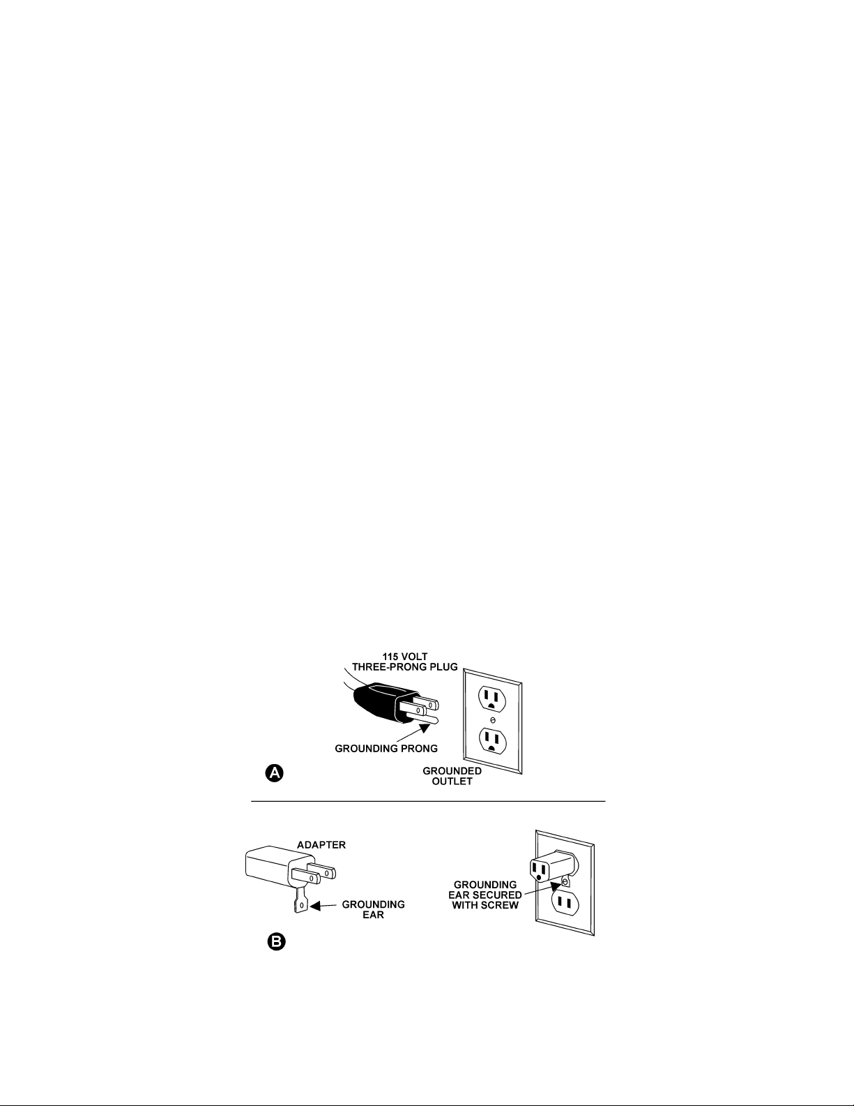
This tool is intended for use on a circuit that has an outlet like t he one in illustration A of Figure 1. The
tool has a grounding plug like the grounding plug in illustration A. A temporary adapter, which look s l ike
the adapter in illustration B, may be used to connect this plug to a two-pole receptacle, as shown in
illustration B, if a properly grounded outlet is not available. ** The temporar y adapter should only be used
until a pr operly grounded outlet can be instal led by a quali fied el ec trici an. The green colored r igid ear or
tab, extending from the adapter , must be connected to a permanent gr ound such as a properly grounded
outlet box.
* Canadian elect rical codes require extension cords to be certified SJT type or bett er .
** Use of an adapter in Canada is not acceptable.
Fig. 1
5
Page 6

Receiving
1. Remove contents from the box.
2. Inspect contents for shipping damage and report
damage, i f any, t o y our distributor.
3. Be sure to keep the box and packing m aterial
should you need to pack t he lathe for mov ing.
4. Do not clean the lathe with anyt hing other than a
damp cloth or a mi ld solv ent. Use of heavy
solvents, paint thinner, gasoline, etc. will
damage paint ed surfaces.
Contents of box (Fig. 2):
1 Lathe (A)
1 Knockout rod (B )
9 10mm B ushings (C)
1 Pen mandrel (D)
1 Live center (E)
1 Spur center (F)
3 Chisels – skew, parting, domed scraper (G)
1 Goggles
1 Owner’s manual
1 Warranty card
Assembly
The JPL-358 is fully assembled and comes ready t o
use right out of the box. However, it is good practice
to thoroughly check the tool for loose fasteners,
handles, etc. before use.
Four holes are provided in the base of the lathe for
bolting it to a table.
Adjustments
Tailstock
Turn handwheel (A, Fig. 3) clockwise to move
tailstock spindle forward; counterclockwise to retract
tailstock spindle. T o lock the spindle, use the lever
(B, Fig. 3).
Loosen the tailst oc k with the attached wrench (C,
Fig. 3) and slide tailstock to desired posi tion. Retighten with wrench.
6
Page 7

Tool Rest
Position the tool rest as close to the workpiece as
possible. It shoul d be sl ightly above the cent er line
of the workpiece.
Loosen the tool rest wit h the attached wrench (D,
fig. 4) and slide tool rest to desired posit ion. Retighten with wrench when finished with adjustment.
Adjust the height of t he tool rest by looseni ng the
lever (E, Fig. 4). Tighten the lever when f inished
adjusting. NOTE: The lever is spring loaded; simply
pull up on i t, rotate it on the pin, and release.
Switch Safety Feature
When the switch is in “off” posi tion, a part of the
switch can be pull ed out (Fig. 5) to prevent
accidental starting of the lat he. The piece must be
re-inserted before operati ng the lathe.
Belt Tension
1. To adjust tensi on of the dri ve belt, open the
cover by turning the knob ( A , Fig. 6) c lockwise.
2. Loosen the screw (C, Fig. 6) usi ng a hex
wrench.
3. Slide t he bearing (B, F ig. 6) left to i ncrease
tension, right to decrease tension.
Belt Replacement
1. To replace the drive belt, open the cover by
turning the k nob (A, Fig. 6) clockwise.
2. Loosen the screw (C, Fig. 6) usi ng a hex wrench
and slide the bearing (B, Fig. 6) to the right.
3. Remove the old belt and install new one around
the pulley s.
4. Re-tension the belt and close the cover.
7
Page 8
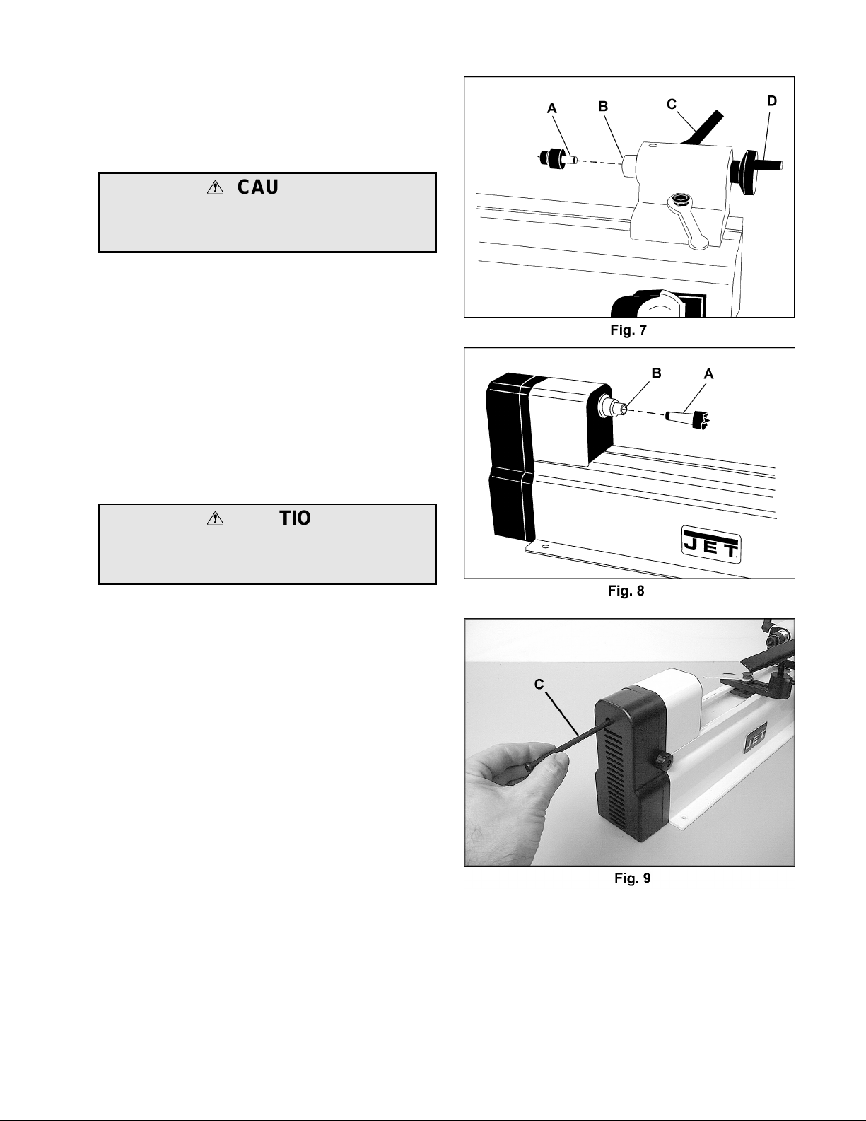
Installing & Removing Live Center
1. Clean the tapered shank of the live c enter (A,
Fig. 7) and the inside of the quill (B, Fig. 7) on
the tailstock.
CAUTION
Failure to clean the live center and quill can
result in separation of the two , which can result
in damage t o the workpiece and possible injury.
2. Install live center i nto the tailstock.
3. To remove the live center, l oosen l ever (C, Fig.
7), and turn handwheel (D, Fig. 7) c ounterclockwise until the live c enter ejects from the
quill.
Installing & Removing Spur Ce nter
1. Clean the shank of the spur center (A, Fig. 8)
and the inside of the headstock spindle (B, Fi g.
8).
CAUTION
Failure t o clean the spur center and spindle can
result in separation of the two , which can result
in damage t o the workpiece and possible injury.
2. Insert the spur center into the spindl e.
3. To remove the spur cent er , insert the knockout
rod (C, Fig. 9) through the hole as shown and
push out the spindle. NOTE: Use your other
hand to catch the spindle as it falls, t o pr event
damage to the tip.
8
Page 9

Installing Pen Mandrel
Screw the mandrel (A, Fig. 10) into the threads in
the headstock spindl e and place the other end on
the tip of the live c enter of the tailstock as shown.
The barrel( s) of a pen can be placed bet ween
bushings, and held snug on the m andr el by the
knurled nut ( B , Fig. 10).
If you ar e new to the practice of pen turni ng, a book
entitled “Pens from the Wood Lathe” (stock #
709123) will demonstrate techniques and tips on
turning, and is available from WMH Tool Group.
Complet e supplies for pen t ur ning are also offered –
see page 4.
9
Page 10

Parts Breakdown for JPL-358 Pen Lathe
10
Page 11

Parts List for JPL-358 Pen Lathe
Index Part
No. No. Description Size Quantity
............ JPL358-HA................... Headstock Assembly (Items 1 thru 8)..... ...............................................1
1.......... JPL358-101.................. Headstock ............................................. ...............................................1
2.......... BB-6003ZZ .................. Ball Bearing...........................................6003ZZ ...................................1
3.......... JPL358-103.................. C-Ring...................................................S-17........................................1
4.......... JPL358-104.................. Spindle Pulley........................................ ...............................................1
5.......... JPL358-105.................. End Cover............................................. ...............................................1
6.......... JPL358-106.................. Main Spindle.......................................... ...............................................1
7.......... BB-6003VV .................. Ball Bearing...........................................6003VV...................................1
8.......... TS-1521031 .................Socket Set Screw.................................. M4x0.7Px8..............................3
9.......... JPL358-109.................. Spur Center ........................................... ...............................................1
10........JPL358-110.................. Fl at Washer........................................... M6x16D ..................................3
11........JPL358-111.................. Connect P late........................................ ...............................................4
12........TS-1482061................. Hex Cap Screw...................................... M6x1.0Px30 ............................2
13........TS-1540041................. Hex Nut................................................. M6x1.0x30..............................2
14........TS-1502021................. Socket Head Cap Screw........................M5x0.8Px10............................1
15........TS-1550061................. Flat Washer...........................................M8 ..........................................1
16........BB-608ZZ ....................Ball Bearing ...........................................608ZZ.....................................2
17........JPL358-117.................. C-Ring...................................................S-8..........................................1
18........JPL358-118.................. Joint Plate ............................................. ...............................................1
19........JPL358-119.................. Pulley Cover.......................................... ...............................................1
20........JPL358-120.................. Knob...................................................... ...............................................1
21........TS-2284202................. Phillips Pan Head Machine Screw .........M4x0.7Px20............................1
22........TS-1550021................. Flat Washer...........................................M4 ..........................................1
23........TS-1541001................. Nylon Nut ..............................................M4x0.7P .................................1
24........TS-2285162................. Phillips Pan Head Machine Screw .........M5x0.8Px16............................5
25........JPL358-125.................. Motor Pulley.......................................... ...............................................1
26........JPL358-126.................. Poly-V Belt ............................................112H.......................................1
27........TS-2361041................. Lock Washer.........................................M4 ..........................................2
28........JPL358-128.................. Motor..................................................... ...............................................1
29........JPL358-129.................. Bed........................................................ ...............................................1
30........JPL358-130.................. Switch.................................................... ...............................................1
31........JPL358-131.................. Handl e Loc k .......................................... ...............................................2
32........JPL358-132.................. Tool Rest Base...................................... ...............................................1
33........JPL358-133.................. Fl at Washer........................................... M6x19D ..................................1
34........JPL358-134.................. Special Wrench..................................... ............................................... 2
35........JPL358-135.................. Bolt........................................................M6x1.0x25..............................1
36........JPL358-136.................. Tool Rest ............................................... ...............................................1
37........JPL358-137.................. Tailstock................................................ ...............................................1
38........JPL358-138.................. Cover ................................................... ...............................................1
39........JPL358-139.................. Cov er .................................................... ...............................................1
40........JPL358-140.................. Quill....................................................... ...............................................1
41........JPL358-141.................. Threaded Stud.......................................M6x1.0Px14............................1
42........JPL358-142.................. Lead S c r ew............................................ ...............................................1
43........JPL358-143.................. Bush...................................................... ...............................................1
44........JPL358-144.................. Copper Washer ..................................... ...............................................1
45........JPL358-145.................. Handwheel............................................. ...............................................1
46........TS-2331051................. Cap Nut.................................................M5x0.8....................................1
11
Page 12

Parts List for JPL-358 Pen Lathe (continued)
Index Part
No. No. Description Size Qty.
............ JPL358-LCK................. Live Center Kit (Items 47 thru 49).......... ...............................................1
47........JPL358-147.................. Live Center Body................................... ...............................................1
48........BB-626VV.................... Ball Bearing...........................................626VV..................................... 1
49........JPL358-149.................. Ti p......................................................... ...............................................1
50........JPL358-150.................. Power Cord............................................ ...............................................1
51........JPL358-151.................. Motor Cord............................................ ...............................................1
52........JPL358-152.................. Copper Plate ......................................... ...............................................1
53........TS-1532042................. Phillips Pan Head Machine Screw .........M4x0.7Px12............................2
54........JPL358-154.................. Star Washer ..........................................M4 ..........................................4
55........TS-1540021................. Hex Nut................................................. M4x0.7P ................................. 4
56........TS-1532032................. Pan Head Screw ....................................M4x0.7Px10............................2
57........JPL358-157.................. Clamp.................................................... ...............................................1
58........JPL358-158.................. Cov er .................................................... ...............................................1
59........TS-1533032................. Phillips Pan Head Machine Screw .........M5x0.8Px10............................4
60........JML-79.........................Goggles................................................. ...............................................1
............ JPL358-PMA................Pen Mandrel Assembly ( Items 61 thru 64) .............................................1
61........JPL358-161.................. Spacer................................................... ...............................................9
62........JPL358-162.................. Taper..................................................... ...............................................1
63........JPL358-163.................. Shaft...................................................... ...............................................1
64........JPL358-164.................. Lock Nut................................................ ...............................................1
65........JPL358-165.................. Knockout Rod........................................ ...............................................1
66........JPL358-166.................. Skew Chisel........................................... ...............................................1
67........JPL358-167.................. Parting Chisel........................................ ...............................................1
68........JPL358-168.................. Domed Scraper Chisel........................... ...............................................1
69........JPL358-169.................. Bolt........................................................M6x1.0x30..............................1
70........JPL358-170.................. L Plate................................................... ...............................................1
71........JPL358-171.................. JET Logo............................................... ...............................................1
72........JPL358-172.................. I.D Label................................................ ...............................................1
73........JPL358-173.................. Warning Label....................................... ...............................................1
12
 Loading...