

Page 1

This .pdf document is bookmarked
Operating Instructions and Parts Manual
JJP-10 BTO S 10" Joint er- P laner
WALTER MEIER (Manuf acturing) Inc.
427 New Sanford Road
LaVergne, Tennessee 37086 Part No. M- 707410
Ph.: 800-274-6848 Revision A1 12/09
www.walt er meier.c om Copyright © 2009 Walt er Meier (M anufacturi ng) Inc.
Page 2

W arranty and Service
Walter Meier (Manufacturing) Inc., warrants every product it sells. If one of our tools needs service or repair, one of our
Authorized Service Centers located throughout the United States can give you quick service. In most cases, any of these
Walter Meier Authorized Service Centers can authori ze warranty repair, assist you in obtaining parts, or perfor m routine
®
maintenance and major repair on your JET
1-800-274-6848.
MORE INFORMATION
Walter Meier is consistently adding new products to the line. For complete, up-to-date product infor mation, check with
your local Walter Meier distributor, or visit waltermeier.com.
WARRANTY
JET products carry a limited warranty which varies in duration based upon the product (MW stands for Metalworking, WW
stands for Woodworking).
WHAT IS COVERED?
This warranty covers any defects in workmanship or materials subject to the exceptions stated below. Cutting tools,
abrasives and other consumables are excluded from warranty coverage.
WHO IS COVERED?
This warranty covers only the initial purchaser of the product.
WHAT IS THE PERIOD OF COVERAGE?
The general JET warranty lasts for the time period specified in the product literature of each product.
WHAT IS NOT COVERED?
Three Year, Five Year and Lifetime Warranties do not cover products used for industrial or educational purposes.
Products with Three Year, Five Year or Lifetime Warranties that are used for industrial or education purposes revert to a
One Year Warranty. This warranty does not cover defects due directly or indirectly to misuse, abuse, negligence or
accidents, normal wear-and-tear, improper repair or alterations, or lack of maintenance.
HOW TO GET SERVICE
The product or part must be returned for e xamination, postage prepaid, to a location designated by us. For the na me of
the location nearest you, please call 1-800-274-6848.
You must provide proof of initial purchase date and an explanation of the complaint must acco mpany the merchandise. If
our inspection discloses a defect, we will repair or replace the product, or refund the purchase price, at our option. We will
return the repaired product or replacement at our expense unless it is determined by us that there is no defect, or that the
defect resulted from causes not within the scope of our warranty in which case we will, at your direction, dispose of or
return the product. In the event you choose to have the product returned, you will be responsible for the shipping and
handling costs of the return.
HOW STATE LAW APPLIES
This warranty gives you specific legal rights; you may also have other rights which vary from state to state.
LIMITATIONS ON THIS WARRANTY
WALTER MEIER (MANUFACTURING) INC., LIMITS ALL IMPLIED WARRANTIES TO THE PERIOD OF THE LIMITED
WARRANTY FOR EACH PRODUCT. EXCEPT AS STATED HEREIN, ANY IMPLIED WARRANTIES OR
MERCHANTABILITY AND FITNESS ARE EXCLUDED. SOME STATES DO NOT ALLOW LIMITATIONS ON HOW
LONG THE IMPLIED WARRANTY LASTS, SO THE ABOVE LIMITATION MAY NOT APPLY TO YOU.
WALTER MEIER SHALL IN NO EVENT BE LIABLE FOR DEATH, INJURIES TO PERSONS OR PROPERT Y, OR FOR
INCIDENTAL, CONTINGENT, SPECIAL, OR CONSEQUENTIAL DAMAGES ARISING FROM THE USE OF OUR
PRODUCTS. SOME STATES DO NOT ALLOW THE EXCLUSION OR LIMITATION OF INCIDENTAL OR
CONSEQUENTIAL DAMAGES, SO THE ABOVE LIMITATION OR EXCLUSION MAY NOT APPLY TO YOU.
Walter Meier sells through distributors only. The specifications in Walter Meier catalogs are given as general infor mation
and are not binding. Members of Walter Meier reserve the right to effect at any time, without prior notice, those alterations
to parts, fittings, and accessory equipment which they may dee m necessary for any reason whatsoever. JET
products are not sold in Canada by Walter Meier.
tools. For the name of an Authorized Service Center in your area call
®
branded
2
Page 3

Table of Contents
Warranty and Service................................................................................................................................2
Table of Contents .....................................................................................................................................3
Warnings..................................................................................................................................................4
Fea ture s ..................................................................................................................................................7
Spe cifi cation s ...........................................................................................................................................7
Optional Accessories ................................................................................................................................7
Shipping Contents ....................................................................................................................................8
Ass embly ............................................................................................................................................... 10
Jointer Setup .......................................................................................................................................... 12
Planer Setup .......................................................................................................................................... 12
Operating Controls.................................................................................................................................. 13
Adju s tmen ts ........................................................................................................................................... 15
Basic Operations .................................................................................................................................... 18
Mai nten ance .......................................................................................................................................... 22
Lu bri cati on ............................................................................................................................................. 22
Troubleshooting ...................................................................................................................................... 23
Parts ...................................................................................................................................................... 26
Electrical Connect io n .............................................................................................................................. 39
The specifications in this manual are given as general information and are not binding. Walter Meier
(Manufacturing), Inc. reserves the right to effect, at any time and without prior notice, changes or alterations to
parts, fitt ings, and accessory equipme nt deemed necessary f or any reason whats oever .
3
Page 4

Warnings
1. Read and understand t he entire owner's ma nual before at t empting assemb ly or oper ation.
2. Read and understand the war nings post ed on the machine and in this manual. Fa ilure t o comply with
all of these warnings may cause serio us injury.
3. Replace the warning labels if they become obscured or removed.
4. This Woodworking Jointer-planer is designed and intended for use by properly trained and
experienced personnel only. If you are not familiar with the proper and safe operation of a
woodw or king jointer or planer, do not use until proper tr aining and knowledge have been obtained.
5. Do not use this for other than its intended use. I f used for other purposes, Walter M eier disclaims any
real or implied warr anty and holds itself harmless f r om any injury that may result from that use.
6. Always wear approved safety glasses/face shields while using this woodworking jointer-planer.
Everyday eyeglasses o nly have impact r esist ant lenses; t hey are not safet y glasses.
7. Before operat ing this woodw orking joi nter-pla ner, r emove tie, ri ngs, wat ches and other jewelry, and
roll sleeves up past the elbows. Remove all loose clot hing and confine long hair. Non-slip footwear or
anti-skid floor str ips are r ecommended. Do not w ear gloves.
8. Wear ear pr otect or s (plugs or muffs) duri ng exte nded periods of oper at io n.
9. Some dust created by power sanding, sawing, grinding, drilling and other construction activities
contain chemicals k nown to cause cancer, birt h defects or ot her reproductive harm. Some e xamples
of these chemicals are:
• Lead from lead based paint.
• Crystalline silica from bricks, cement and other masonry products.
• Arsenic and chromium fr om chemically treated lumber.
Your risk of exposure varies, depending on how often you do this type of work. To reduce your
exposure to these chemicals, work in a well-ventilated area and work with approved safety
equipment, such as face or dust masks that are specifically designed to filter out microscopic
particles.
10. Do not operate this machine while tired or under the influence of drugs, alcohol or any medication.
11. Make cer t ain the switch is in the OFF position before connecti ng the machine t o t he power s ource.
12. Make cer t ain the machine is properly grounded.
13. Make all machine adjustme nts or maintenance with the machine unplugged from the power source.
14. Remove adjusting keys and wrenches. Form a habit of checking to see that keys and adjusting
wrenches are removed from the mac hine before tur ning it on.
15. Keep safety guards in place at all times when the machine is in use. If removed for maintenance
purposes, use extreme cautio n and replace t he guards immed iately.
16. Make sure the woodw or king jointer- planer is firmly secured to t he floor or benc h before use.
17. Check damaged parts. Before further use of the machine, a guard or ot her part that is damaged
should be carefully checked to determine that it will operate properly and perform its intended
function. Check for alignme nt of moving part s, binding of moving part s, break age of part s, mounting
and any other condit ions t hat may affect its oper ation. A guard or other part that is damaged s hould
be properly repaired or r eplaced.
18. Provide for adequate space surrounding work area and non-glare, overhead lighti ng.
19. Keep the floor around t he machine clean and free of sc r ap material, oil and grease.
4
Page 5

20. Keep visitors a saf e dist ance from the wor k ar ea. Keep children away.
21. Make your workshop child proof with padlocks, master switches or by removing start er keys.
22. Give your work undivided att ention. Looking aro und, carrying on a conversat ion and “horse-play” are
careless acts that can result i n serious injury.
23. Maintain a balanced stance at all t imes so that you do not fall or lean against the cutterhead or other
moving parts. Do not overreac h or use excessive for c e t o perfor m any machine operation.
24. Use the right tool at t he correc t speed and feed rate. Do not force a tool or at t achment to do a jo b f or
which it was not designed. The r ight t o ol will do t he job b e tter a nd sa fer.
25. Use recommended accessor ies; improper acc essor ies may be hazardous.
26. Maintain too ls with care. Keep knives sharp and clean for t he best a nd safest performance. Follow
instructions for lubricat ing and changi ng accessori es.
27. Turn off t he mac hine bef or e cleaning. Us e a br ush or co mpress ed air t o r emo ve c hips or debr is — do
not use your hand s.
28. Do not stand on the machine. Serio us injury co uld occur if the machine tips over.
29. Never lea ve the machine r unni ng unattended. Turn the power off and do not leave the machine until it
comes to a complete stop.
30. Befor e turni ng on machine, remove all extra equipme nt such as keys , wrenches, scrap, stock, and
cleaning rags aw ay from the machine.
31. Always use a hold-dow n or p ush block when s urfacing stock less t han 12" inches lo ng, or 3 i nches
wide, or 3 inc hes thick.
32. Do not perform joi nting oper ations on material shorter than 8", narrow er than 3/4" or less than 1/4"
thick.
33. The hands must never be closer t han 3 inches t o
the cutter head (see Figure).
34. Never apply pressure to stock directly over the
cutterhead. This may res ult in the stock tipp ing
into the cutterhead along with the operator's
fingers. Position hands away f r om extreme ends
of stoc k, and push thro ugh with a s moot h, even
motion. Never back workpiece t ow ar d the infeed
table.
35. To avoid kickback, the grain must run in the
same direction you are cutting. Before
attempting to joint, or plane, each work piece
must be caref ully examined for stock co ndition
and grain orientation.
5
Page 6

36. When w or king w ith a swirl grai n wood or burls, making it necessary t o plane against the grai n, use a
lesser depth of cut and a slow rate of feed.
37. Move the hands in an alternate motion from back to front as the work continues through the cut. Never
pass the hands direct ly over the cutter knife. As one hand approaches the knives remove it f rom the
stock in an arc motion and place it back on the stock in a position beyond the cutter knife (Fig. 18).
38. At all times hold the stock f irmly.
Familiarize yourself with the following safety notices used in this manual:
This means that if precautions are not heeded, it may result in minor injury and/or
possible machine damage.
This means that if pr ecautions are not heeded, it may result in serious injury or possibly
even death.
- - SAVE THESE I NSTRUCTI ONS - -
Read and understand the entire contents of this manual before attempting
assembly or operation! Failure to comply may cause serious injury!
6
Page 7
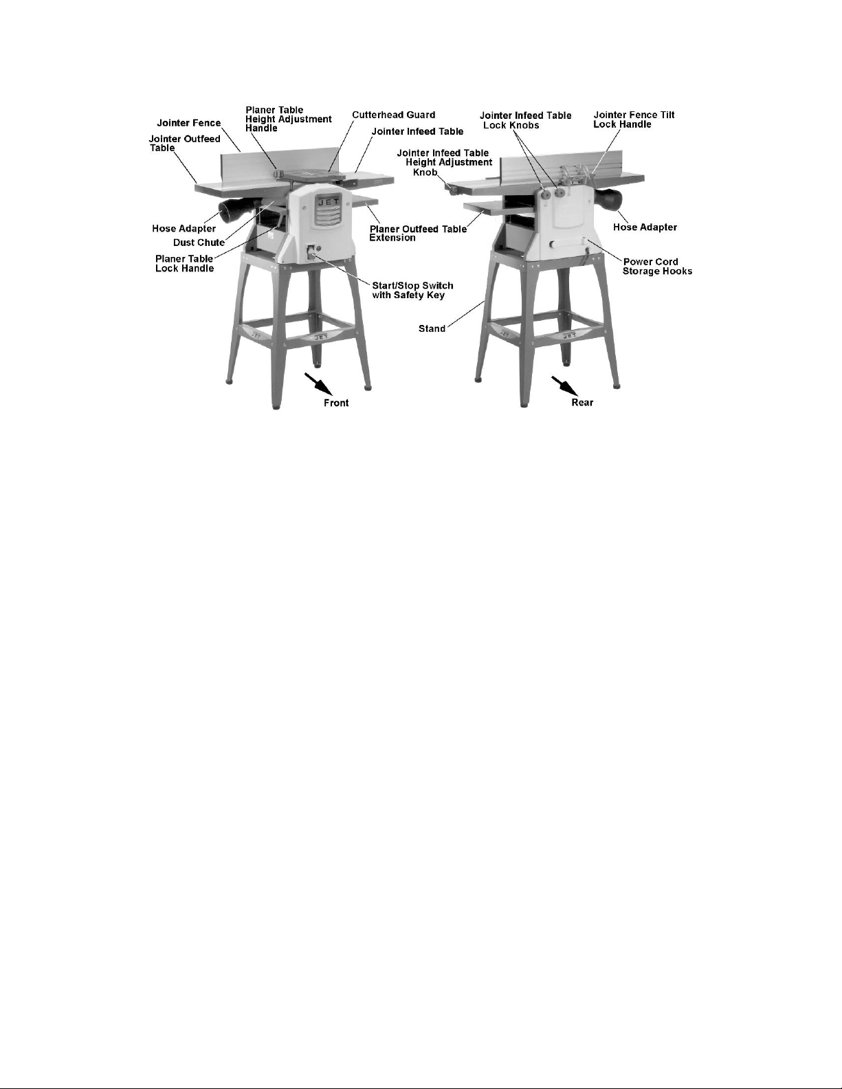
Features
Features
Specifications
Model number .................................................................................................................. J JP-10B TOS
Stock number ........................................................................................................................... 707410
Cutterhead speed ................................................................................................................... 9000rpm
Number of knives................................................................................................................................ 2
Cutter knife length...................................................................................................................... 10-1/4"
Cutter knife thickness .................................................................................................................. 0.060"
Dust port diameter ............................................................................................................... 2-1/2" or 4”
Jointer table ....................................................................................................................... 36" x10-1 /4 ”
Max stock removal .......................................................................................................................... 1/8”
Max cutting width ............................................................................................................................. 10"
Fen ce ................................................................................................................................ 4-7/8" x 25”
Fence tilt .............................................................................................................................. 90°- 45° R
Fence positive stop ................................................................................................................ 90° , 45° R
Planer table ................................................................................................................. 10-3/ 4" x 10-1/2"
Planer capacity
Maximum cutting thickness ........................................................................................................ 4-1/2"
Max depth of cut ........................................................................................................................... 5/64”
Min length of work piece.....................................................................................................................6"
Feed rate ................................................................................................................................19. 5 f pm
Motor
Voltage ................................................................................................................... 120V, 60Hz, 13A
Switch ...................................................................................... Toggle switch with overload prot ec t ion
Overall Dimensions (LxWxH) ............................................................................... 37-1/2" x 18-1/2" x 44"
Net weight ................................................................................................................................... 74 lbs
Optional Accessories
Stock No. Description
707411 10" Jointer / Planer Blades
709207 13" Roller Support Stand
7
Page 8
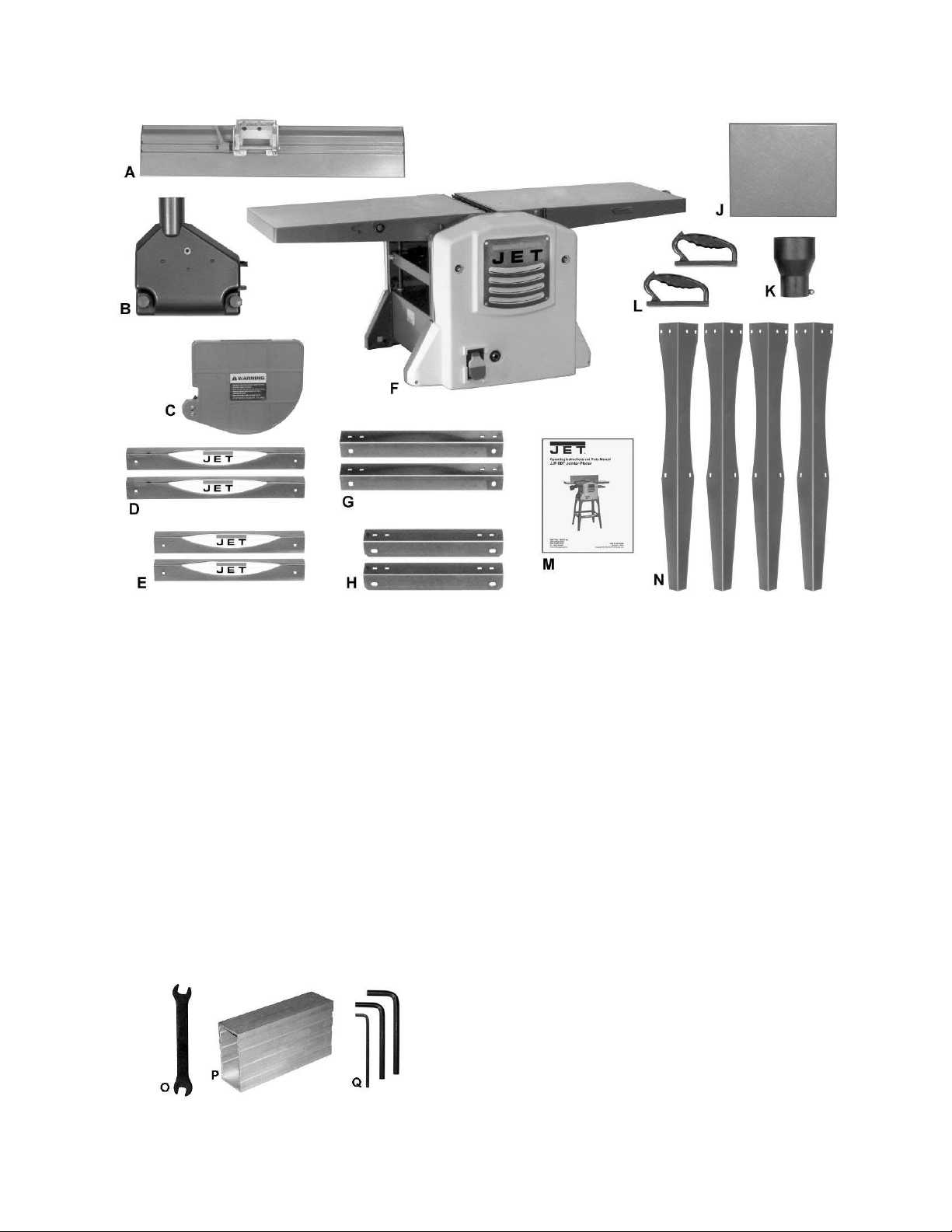
Shippi ng Cont ents
Figure 1 – Contents of the Mai n Carton
Unpacking
Remove all contents from the shipping carton.
Do not discard the carton or packing material
until your Model JJP-10BT Jointer-Planer is
assembled a nd is running satisfact or ily.
Compare the conte nts of the cart on against the
list of parts in Contents of Shipping Container
(below). The letter identification in the list
corresponds to t he items s hown at rig ht. This is
your key for identifying the parts used
throughout the Assembly section for easy
reference.
Remove the prot ective coating t hat is app lied to
the table with a house hold grease and spot
remover.
Contents of t he M ain Cart on
01 Jointer Fence (A)0
01 Dust Chute (B)
01 Cutter head Guard (C)
02 Long Support Plate( D)
02 Short Support Plate ( E)
01 Jointer-Planer (F)
02 Long Stand Top Support ( G)
02 Short St and Top Support ( H)
01 Planer Outfeed Table E xtension (J)
01 2-1/2" to 4" Hose Adapter (K)
02 Push Block (L)
01 Owner's Ma nual (M)
04 Stand Leg (N)
Tools Included
Figure 2 – Tools Included
01 8/10mm Ope n-e nd Wrench (O)
01 Knife Sett ing Gauge (P)
01 3, 5, 6mm hex wrenches (set of 3) (Q)
8
Page 9
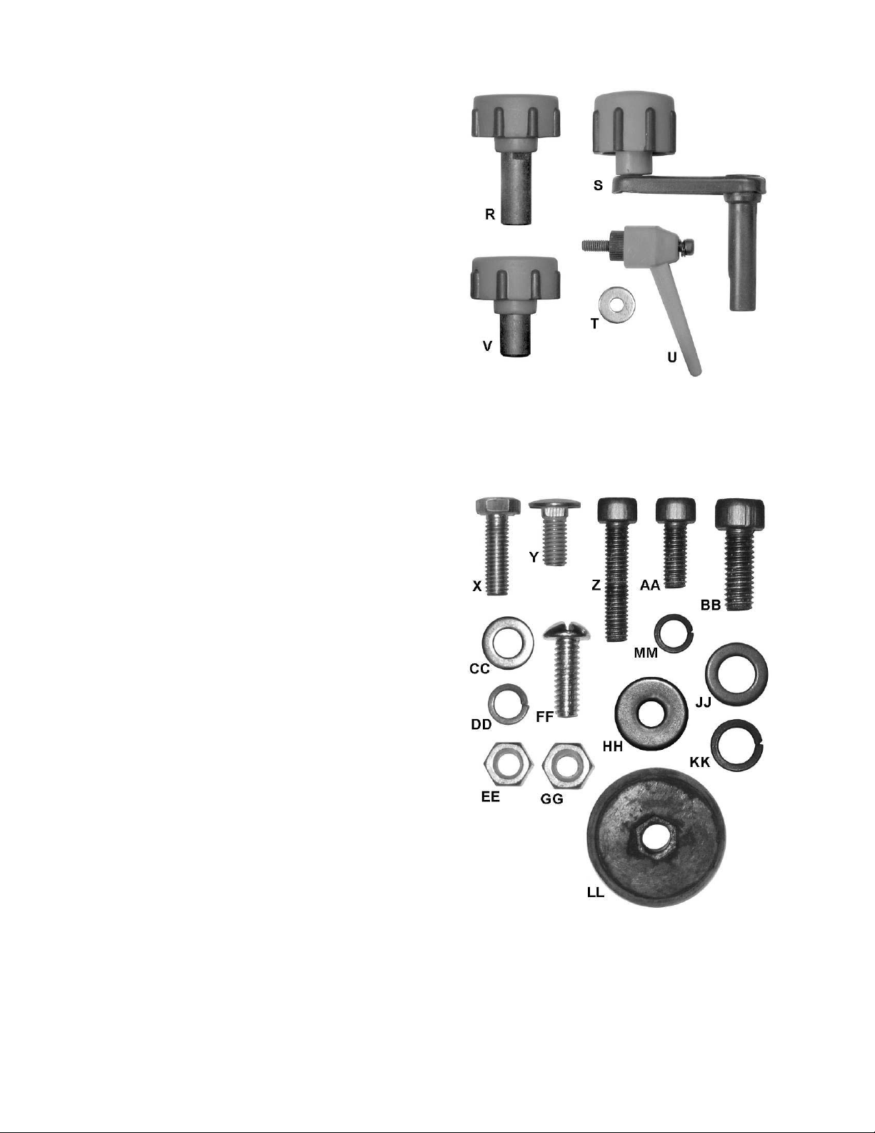
Knobs and Handles
01 Lock Knob (R)
01 He i ght Adj ust Handle (S)
01 Lock Handle ( U)
01 Flat Washer (T)
01 Lock Knob (V)
Figure 3 – Knobs and Handl es
Hardware
04 Hex Cap Screw( X)
24 Carriage Bolt (Y)
02 Socket Head Cap Screw ( Z)
03 Sock et Head Cap Screw ( AA)
04 Sock et Head Cap Screw ( BB)
28 Flat Washer (CC)
24 Lock Washer (DD)
28 Hex Nut (EE)
02 Pan Head Machi ne Screw ( FF)
02 Hex Nut (GG)
03 Flat Washer (HH)
04 Flat Washer (JJ )
04 Lock Washer (KK)
04 Rubber Foot ( LL)
02 Lock Washer (M M )
Figure 4 – Har dware ( actual siz e)
9
Page 10
Assembly
For assembly convenience, the item letter
designators used t hrougho ut the Assembly section
are the same as those used to identify shipping
content and hardware components on pages 8–9.
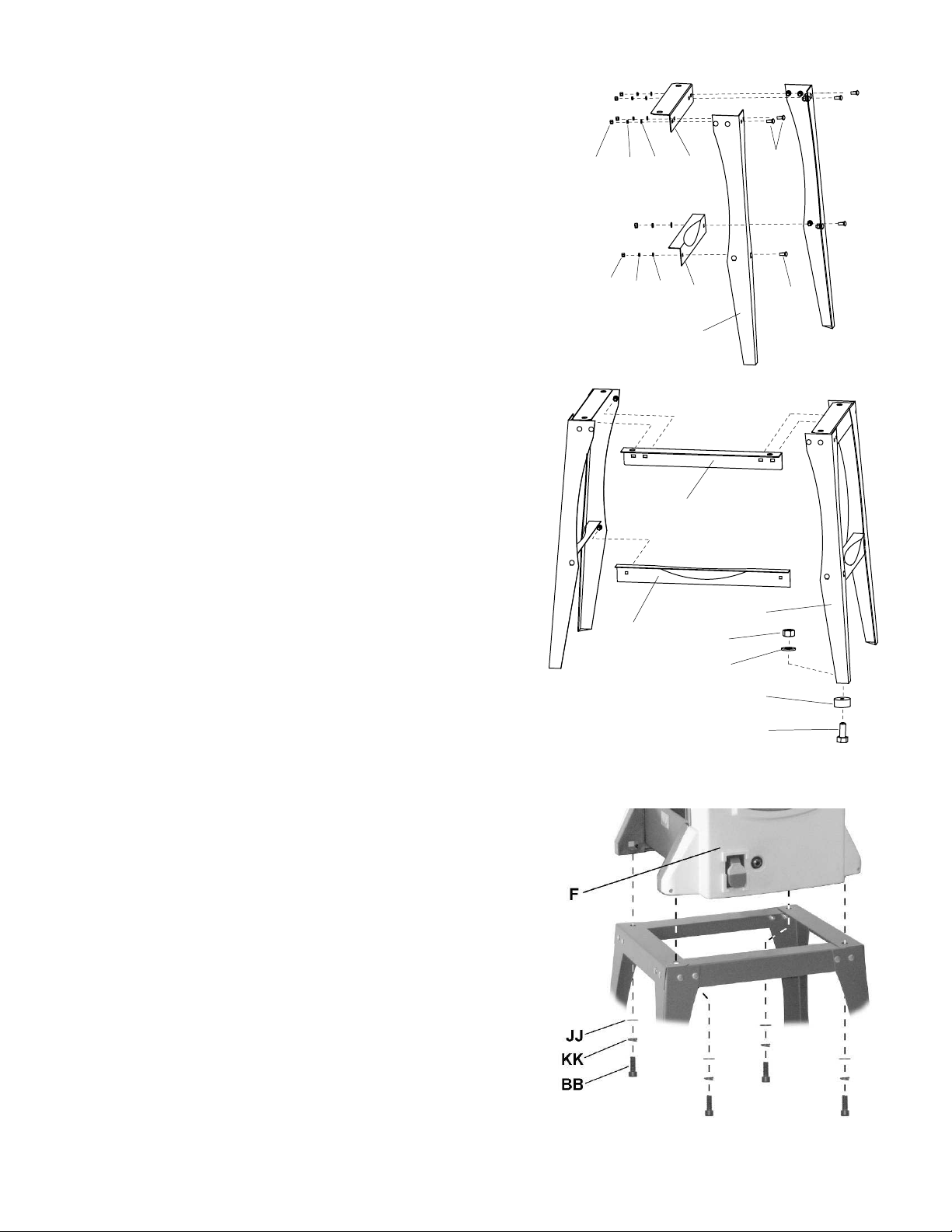
Stan d Assembly
Referring to Figure 5:
1. Select two legs (N),one shor t stand top s upport
(H) and one short support plate (E).
2. Attach one end of the stand top support (H) to the
top of the first leg with two carriage bolts (Y), flat
washers (CC), lock washers (DD) and hex nuts
(EE). Attach the other end of the stand top
support (H) to the second leg in the same
manner. Hand-tighten only at this time.
3. Attach a support plate (E) to each leg (N) in the
same manner with two carriage bolts (Y), flat
washers (CC), lock washers (DD) and hex nuts
(EE). Hand-tighten only at this time.
4. Repeat steps 1–3 using the remaining legs,
short stand top support and support plat e.
EE
EE
DD
DD
CC
CC
H
E
N
G
Y
Y
5. Complete the stand construction by attaching
long stand top supports (G) and long support
plates (D) to the leg assemblies co nstructed in
steps 1–4. Hand-tighten all hardware only at t his
time.
6. Place a r ubber foot (LL) on a hex cap screw (X),
then insert t he threaded end of the screw through
the opening on the bottom of the leg.
7. Secure with fla t wa s h er (CC) and hex nut (EE).
8. Attach r ubber feet t o r emai ni ng legs i n t he sa me
manner.
9. Place sta nd upright. E nsure that the stand is on
a level s urface a nd all f our legs are contact ing
the surface.
10. Tighte n all hex nuts w ith t he 10mm wrench (O )
provided.
M ou nting Joi nter-Planer to St and
Referring to Figure 6:
1. Place the Jointer-Planer (F) onto the assembled
stand and secure with 4 each socket head cap
screws (BB), l ock washers (KK), and fl a t wa s h er s
(JJ).
2. Tighten all socket head cap screws (BB) with
the 5mm hex wrench (Q) provided.
B
D
EE
CC
LL
X
Figure 5
Figure 6
10
Page 11
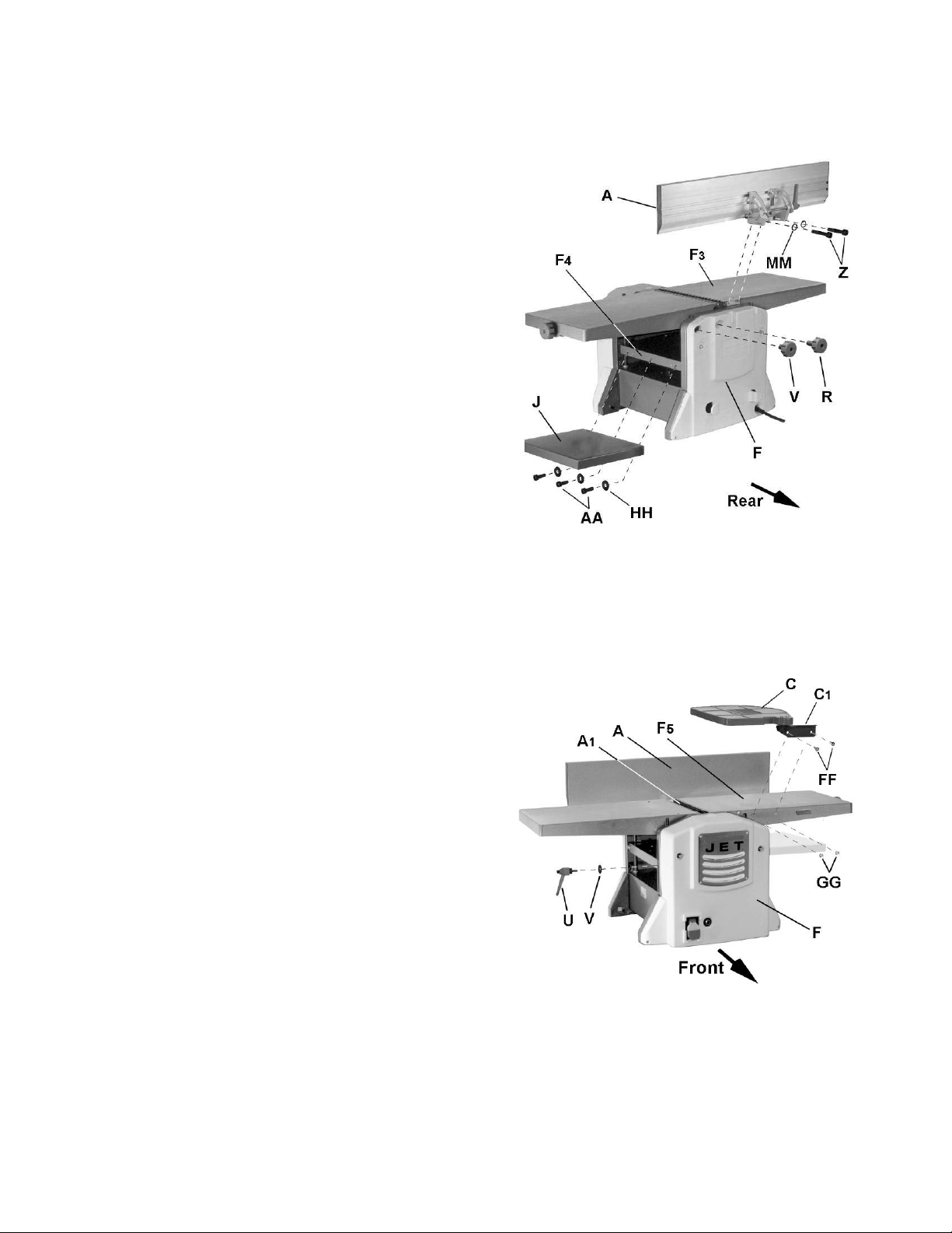
Joi nter-Planer Assemb ly
Referring to Figure 7:
Fence
1. Attach jointer fence (A) to back of jointer outfeed
table (F3) wit h two each socket head cap screws
(Z) and lock washers (MM). Tighten screws with
5mm hex wrench (provided).
Lock Knobs
The JJP-10BT Jointer-Planer comes equipped with
two lock knobs to secure the positi on of the joi nter
infeed table.
2. Install jointer infeed table lock k nobs (V, R).
Note: The shaft length of each lock knob (refer
to Figure 3) are diff er ent. Be sure to install eac h
in the correct location.
Exten sion Table
3. Attach the planer o utfeed extensi on table (J) to
the main planer table (F4) with three each
socket head cap screws (AA) and flat washer s
(HH). Tighten screws with 5mm hex wrench.
Exten sion Tabl e A dj ustment
Two setscrews located underneath the extension
table (J ) ar e used t o adjust the heig ht positio n of the
outer (protruding) edge, which must be slightly
higher than the main planer table (F4) in order to
minimize snipe (see Avoidi ng Sni pe on page 21).
4. Using a 4mm hex wrench (provided), turn
setscr ews slightly clockwise to raise t he table or
counterclockwise to low er t he table.
Lock Handle
Figure 7
Referring to Figure 8:
Attach pla ner ta ble lock handle (U) and flat washer (T).
Cutterhead G uar d
5. Install cutterhead guard (C) by securing the
bracket (C1) to the side of the jointer infeed
table (F5) with two each pan head machine
screws (FF) and hex nuts (GG).
Important: It is extremely important that spring
action causes the cutterguard ( C) to retrac t against
the fence (A), concealing the cutterhead (A1). If
spring return tension is not enough, adjust the spring
located on the cutterhead pivot shaft acc or di ngly.
Figure 8
11
Page 12
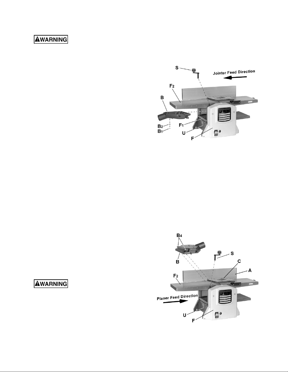
Jointer Setup
Disconnect mach ine from power
source before making any adjustments. Failure
to comply may cause serious injury.
Referring to Figure 9:
1. Loosen lock handle (U).
2. In st all planer tabl e height adj ustment handle (S) .
3. Turn handle (S) counterclockwise and lower
planer table (F1) all the w a y .
4. Remove hex nu t (B1) and flat washer (B2) fro m
dust chute (B).
5. Orient the dust chute (B) as shown and install
into the infeed opening.
Position the chute (B) such that the two
positioning keys and one threaded positioning
screw underneat h the c hute mes hes with three
positioning holes o n the table (F1).
6. Raise the table (turn handle S clockwise) until
the dust chute (B) is held firmly in place
between t he planer inf eed table (F1) and jointer
outfeet table (F2). Do not overtighten.
7. Tighten lock handle (U).
Step 8 is optional.
8. Furt her secure the d ust chute by reinstalling the
hex nut (B1) and flat washer (B2) from
underneath the planer infeed table (F1).
9. Remove handle (S).
Figure 9
Important: Dust chute (B) must be proper ly i nstalled in
both Jointer setup and Planer setup. If improper
installation fails to activate a micro-switch, the machine
will n ot st art.
Planer Setup
If the machine is currently set up for jointer
operation, re move the dust chute (B, Fig. 9). Refer
to the Join te r Setup sect ion above.
Referring to Figure 10:
1. Swing cutterguard (C) away from fence (A),
which will e xpose t he cutte rhead.
Cutterhead knives are
dangerously sharp. Use extreme caution when
working around them. Failure to comply may
cause serious injury .
2. Orient the dust chu te (B) as show n. Install o nto
the jointer outfeed table (F2) and secure by
tightening l oc k knobs (B4).
Figure 10
12
Page 13

Operating Controls
Disconnect mach ine from power
source before making any adjustments. Failure
to comply may cause serious injury.
Power
Plug power cord into outlet.
Referring to Figure 11:
Start/Stop
Pull the red switch (A) out to start. Push in to stop.
Safety Key
Removing the safety key (B) will render the
start/stop switch inoperable. The machine can
continue to operate without the key, but upon
stopping cannot be r est arted until it is reinstalled.
Rese t Swit ch
If t he machine sho uld come to a n unexpect ed stop
during operation due to overload or jammed workpiece, etc. :
1. Set the start/stop switch (A) set to stop (pushed
in).
2. Momentarily press, t hen release the reset switch
(C).
3. Restart machine.
Planer Controls and Adjustments
Referring to Figure 12:
Table Lock
Turn the lock handle (A) counter clockw ise t o r elease
and permit table adjustment. Turn the lock ha ndle
(A) clockwise to secure the planer table (D) in its
selected positio n.
Table Height Adjustment
The planer table height is set as f ollows:
1. Unlock the table lock (A).
Figure 11
2. Install the removeable adjustment handle (C)
onto the shaft (B).
3. Rotate the adjustment handle (C) clockwise to
raise the planer table (D), counterclockwise to
lower.
Each revolution of the adjustment handle (C) results
in a 3/32" up or down movement of the table (D). A
scale indicates t he amount of table travel. The pointer
(E) indicates the table position on the scale relative to
the cutterhead.
Figure 12
13
Page 14

Joi nter Cont rols and Ad justmen t s
Refer to Figure 13.
Infeed Tabl e Hei ght Adj ustment
Two lock knobs (F) and a height adjustment knob
(E) control t he height adj ustment of t he infeed tabl e
(D).
To adjust:
1. Loosen lock knobs (F).
2. Turn the height adjustment knob (E) clockwise
to raise the i nf eed table (D) or counter-clockwise
to lower the table.
The amount of table adj ustment can be read o n
the scale (C).
3. Tighten the l ock knobs (F).
Note: A depth of cut of 1/16" or less is recom-
mended.
Cutterhead G uar d
Properly positio ned, t he cu tterhead guard (A) should
rest against the fence (B1).
Fence Bevel Adjustment
The fence (B2) can be tilted backward (G) up to 45°
(that is, f or a total included angle of 135° f rom table
surface) as f ollows:
1. Loosen lock handle (J).
2. Tilt the fence (B2) back to the desired angle up
to 135 degrees (G). Or you can place your
beveled reference piece on the table and
against the fence, adjusting the fence until the
angle of the fence matches the bevel of your
gauge piece.
3. Tighten the l ock handle (J).
Figure 13
14
Page 15

Adjustments
Cutt erhead Kni f e Adjust ment
Cutterhead knives are
dangerously sharp! Use extreme caution when
inspecting, removing, sharpening or replacing
knives into the cutterhead. Failure to comply
may cause serious injury!
Determining if adjustment is necessary:
1. Disconnect machi ne from the power s ource.
2. Remove the cutterhead guard.
Referring to Figures 14 and 15:
Note: To rotat e t he c utterhead the cutter head pulley
must be turned. T his req uires r emo ving t he panel o n
the front of the cabinet for access.
3. Rotate the cutterhead (E) until one knife is i n t he
12 o'clock positio n. The 12 o'clock position is the
highest point a b lade w il l reach in the cutting ar c
(C, Fig. 15) .
4. Place the knife setting gauge (J) on the outfeed
table (F). One end of the gauge should be
positioned over the cutting knife (C) towards the
near the end of the blade (G).
Use care when handling the knife
setting gauge near the blades to prevent damage.
Note the position of the knife blade wit h respect
to the gauge, the n move the ga uge to the other
side of the table towards the fence (H) and
again note the position of the knife blade with
respect to the gauge.
The blade must be at the same heig ht at each
end and m ust also be at the same heig ht as the
outfeed table (bot t om of gauge). If t his is not t he
case, adjustment is required as follows:
Adj ustment procedure
Figure 14
C
B
A
D
E
5. Slightly loosen seven gib lock screws (A) by
turning into the lock bar (B), clockwise as
viewed fr om the infeed tabl e (K).
6. Adjust the blade height by turning jack screws
(D) upon which the blade rests. To lower the
blade, turn the screw clockwise. To raise, turn
the screw counter- clockwise.
7. When the blade is at the proper height, alternately
tighten the seven gib lock screws (A).
Repeat steps 3 – 7 to adjust the remaining blade.
Note: The most common cause for unsatisfactory
cutting perfor mance is improperly set k nives. Many
aftermarket devices are avaialable to further assist
in the accurate setting of knives.
Figure 15
15
Page 16

Repl aci ng Cut t er Knives
Disconne ct machine fro m power
source before making any adjustments. Failure
to comply may cause serious injury.
1. Disconnect machi ne from the power s ource.
2. Remove the cutterhead guard.
Cutterhead knives are
dangerously sharp. Use extreme caution when
inspecting, removing, sharpening, or replacing
knives into the cutterhead. Failure to comply
may cause serious injury.
Referring to Figures 14 and 15 (page 15):
3. Turn all seve n gib lock screws (A) into the lock
bar (B) by turning in a clockwise direction as
viewed fr om the infeed tabl e (K).
4. Carefully remove the cutter knife (C) and lock
bar (B).
5. Repeat for the remaining knife.
6. Thoro ughly clea n all surfaces of the cutter head,
knife slots and lock bars of any dust or debris.
7. Insert the first replacement knife (C) into the
knife slot, making sure it faces the proper
direction.
8. Insert lock bar (B) and tighten just enough to
hold in place.
9. Repeat for other the remaining blade.
Following installation, the knives must be adjusted
as described in Cutterhead Knive Adjustment on
page 15.
Joi nter Fence Adjust ment
Referring to Figure 16:
The jointer fence (A) ca n be adj usted f r om a full forw ar d
position (90º to t able, cor responding to a scale readi ng
of 0º) t o a f ull back-t ilted position of 13 5 º (s cal e r eading
of 45 º).
If sett ing to ma ximum pos itions do not st op the fence at
0º or 90º, make adjustments as follows:
Fence 90º Adjustment
1. Loosen lock handle (H) and bring fence fully
forward. Using a square, determine if t he fence is
90º to the table.
If adjustment is required:
2. Loosen jam nut (E) a nd adjust stop screw (D) in or
out until a fenc e postion of 90º with respect to the
table is achieved.
3. Secure the jam nut (E).
Check the scale i ndication. If t he indicator ( C) does not
point to zero:
4. Loosen screw (B), adjust accordingly, then retighten
screw.
Fence 45º Adjustment
Verify that the fence and scale indication is accurate at
90º as outlined in Fence 90º Adjustment abo ve.
1. Loosen lock handle (H) and set the fence all the
way back. Using a sq uare, det ermine if the fence is
135º to the table.
If adjustment is required:
2. Loosen jam nut (G) and adj ust stop screw (F) in or
out until a fe nce post ion of 135º w it h respect to the
table is achieved. Note: The screw head stops
against the fence mounting bracket .
3. Secure the jam nut (G).
16
Figure 16
Page 17

Belt Replacement
Refer to Figure 17 when installing or replacing the
the feed-roller (A) or cutterhead drive (D) belts.
Disconne ct machine fro m power
source before making any adjustments. Failure
to comply may cause serious injury.
Feed-rol l er Bel t Replacement
Cutterhead knives are
dangerously sharp. Use extreme caution when
replacing any belt. Contact with cutterhead
knives will cause serious in jury.
1. Remove the f r ont pa nel. This is the panel where
the Start/Stop switch is located.
2. Remove feed-roller belt (A) from pulley (B) while
manually rotating pulley (C).
When this is accomplished, belt will fall away
from pulley (C).
3. Loop the new belt around pulley (C), then
around pulley (B) while ma nually rot ating pulley
(C).
4. When installed, continue to manually rotate
pulley (C) and verify that be lt is properly seat ed
on both pulleys.
5. Replace front cover.
Cutterhead D r i ve Belt Repl acement
Cutterhead knives are
dangerously sharp. Use extreme caution when
replacing any belt. Contact with cutterhead
knives will cause serious in jury.
The cutterhead drive belt should seldom if ever,
require replace ment. Fo llow t he proce dure be low if,
however, t he belt should require replacement.
1. Remove the feed-roller belt as described in
Feed-rol ler Belt Replacement above.
2. Remove the bottom portion of the cutterhead
drive belt (D) from pulley (E) while manually
rotating pulley (F).
Figure 17
4. Install new belt by first feeding the lower loop
downward behi nd the gear ( H) and pulley (C). This
will properly position the lower loop of the belt in
close proximity t o pulley (E).
5. Slide t he top loop of the belt aro und and past pulley
(B), sliding it underneath and past chain (G); then
loop around pulley (F).
6. Loop belt around pulley (E) while ma nually r otat ing
pulley (F).
Use extreme caution to avoid
contact with cutt er head knives whi le perf orm ing t his
step. Contact with cutterhead knives will cause
ser io u s injur y .
Use extreme caution to avoid
contact with cutt erhead k nives whi le perform ing
this step. Contact with cutterhead knives will
cause serious injury .
3. Remove top portion of belt (D) from pulley F,
then work it under the chain and past pulley B to
remove completely.
7. M anually rotate p ulley (F) t o ver ify that t he grooves
in the belt are properly meshed with t he grooves on
both pulleys.
This completes t he cutter head drive belt i nstallation.
8. Replace the feed-roller belt (Feed-roller Belt
Replacement section steps 3–5).
17
Page 18

Basic Operations
Hand pla cement
Dust Collection
Before initial operation, the machine must be
connected to a dust collector.
Important: If a dust collection system is not
used, t he qualit y o f your cut will s uffer s e ver e ly .
Initial Startup
After the assembly and adjustments are
complete t he pla ner is ready to be t ested. Plug
in and start the machine. Keep your finger on
the Stop button in case of a problem. The
machine should run smoothly with little or no
vibration or rubbing noises. Investigate and
correct the source of any problems before
further operatio n.
DO NOT attempt to inves-
tigate or adjust the pl aner while it is running.
Wait until the machine is turned off,
unplugged a nd all work ing parts have co me
to a complete standstill.
Always wear ANSI-approved
safety glasses or goggles when operating
equipment.
Never pass hands directly
over the cutt er head.
Referring to Figure 18:
At the start of the cut, the left hand holds the
workpiece firmly against the infeed table and
fence w hile the right ha nd pushes the workpiece
in a smooth, even motion towar d t he cutter head.
After t he cut is under way, the new surface r es t s
firmly on the outfeed table. The left hand is
transferred to the outfeed side (Figure 18) and
presses down on this part of the workpiece, at
the same time maintaining flat contact with the
fence. The right hand presses the workpiece
forward and before the right hand reaches the
cutterhead it should be moved to the work on
the outfeed table.
Surfac ing
The purpose of surfacing on a jointer is to
produce one flat surface (Figure 19). The ot her
side can then be milled to precise, final
dimensions on a t hickness planer res ulting i n a
board that is smoot h and flat on bot h sides a nd
each side parallel to t he other.
!
If the wood to be jointed is cupped or
bowed, place the concave side down, and
take light cuts until the surface is flat.
Changing Mode of Operation
When changing the operating mode (planer to
jointer and back) t he machine must be turned off,
unplugged, and come to a complete stand-still.
To change the mode of operation, see sections
Jointer Se tu p and Planer Setup on page 12.
Joi nter Operations
Correct operat i ng position
The operator must be positioned offset to the
infeed table (Fig ure 18).
Figure 18
!
Never s urface pieces shorter t han 12 inches
or thinner tha n 3/8 inch wit hout the use of a
special work holding fi xture.
!
Never s urface pieces thinner t han 3 inches
without the use of a push block.
!
Cuts of appr oximately 1/ 16" or less at a t ime
are recom me nded, which pro vides f or bet t er
control over the material being surfaced.
More passes c an t hen be made to reac h t he
desired depth.
Figure 19
18
Page 19

Di re ction of Grain
Avoid feeding work into the jointer against the
grain (Figure 20).
Figure 20
This may result in chipped and splintered edges.
Feed with the gra in to obt ain a sm ooth s urface,
as shown in Figure 21.
Edge Jointi ng
Jointing (or edging) is t he process of cr eating a
finished, flat edge surface that is suitable for
joinery or finishing (Figure 22). It is also a
necessary step prior t o ripping stock t o width on
a table saw.
!
Never edge a board that is less than 3
inches wide, l ess than 1/4 inch t hick, or 12
inches long, without usi ng a push block.
!
When edging wood wider than 3 inches lap
the fingers over the top of the wood,
extending them back over the fence such
that they will act as a s top for the hands in
the event of a kickback.
When workpiece is twice the
length of the jointer inf eed or out f eed t able
use an infeed or outf eed suppor t .
To edge:
1. Make sure the fence is set to 90°. Double
check it with a square.
2. Inspect stock for soundness and grain
direction (refer to Direction of Grain on
previous page).
Figure 21
Figure 22
3. If the board is bowed (curved), place the
concave edge down on the infeed table.
4. Set the infeed table for a cut of approximately 1/16 inch.
5. Hold the st ock firmly against t he fence a nd
table, f eed the stock slowly a nd evenly over
the cutterhead.
19
Page 20

Beveling
Beveling an edge is the same operatio n as edge
jointing, except that the fence is tilted to a
specified angle.
!
Make cert ain material be ing beveled is over
12 inches lo ng, mor e t han 1/4 inch thick and
1 inc h wide.
To bevel:
1. Use a bevel ga uge to determine t he desired
angle. Then set the fence to the same angle.
2. Inspect stock for soundness and grain
direction (refer to Direction of Grain on
previous page).
3. Set the infeed table for a cut of
approximately 1/ 16.
4. If the board is bowed (curved), place the
concave edge down on the infeed table.
5. Feed the stock through the cutterhead,
making sure the face of the stock is
completely flat against the fence and the
edge is making solid contact on the infeed
and outfeed tables (Fig ure 23).
For wood wider than 3 inches – hold with
fingers close together near the top of the
stock, lapping over the board and exte nding
over the fence.
For wood less than 3 inches wide – use
beveled push blocks and apply pressure
toward the fence. Keep fingers near top of
push block.
Several passes may be req uired to achieve f ull
bevel.
lowering the planer table (D, Fig. 12) using the
adjustable handle (C, Fig. 12).
!
The quality of thickness p laning depe nds on
the operator's judgment about the depth of
cut.
!
The depth of cut depends on the width,
hardness, dampness, grain direction and
grain structure of t he wood.
!
The maximum thickness of wood that can be
removed in one pass is 5/64" for planing
operations on workpieces up to 5-1/2” wide.
The workpiece must be positioned away from
the center tab on the rollercase to cut 1/8”.
!
The maximum thickness of wood that can be
removed in one pass is 1/16” for planing
operations o n work pieces fr om 5-1/2” up to
10" wide.
!
For optimum planing performance, the dept h
of cut should be less than 1/16”.
!
The board should be planed with shallow
cuts until t he work has a level si de. Once a
level surface has been created, flip the
lumber and create parallel sides.
!
Plane alternate s ides unti l the desired t hickness is obtained. W he n half of the tot al cut
has been taken from each side, the board
will have a uniform, moisture content and
additional drying will not c ause it to warp.
!
The depth of c ut should be shallow er when
the workpiece is wider.
!
When planing hardwood, take light cuts or
plane the wood in thin widths.
!
Make a test cut wit h a test piece and verify
the thickness produced.
Figure 23
Planer Operatio ns
Dept h of Cut
Thickness planing refers to the sizing of lumber to
a desired thickness while creating a level surface
parallel to the opposite side of the board. Board
thickness that the pla ner will pr oduce is indicate d
by the scale (see Table Height Adjustment on
page 13). Preset the planer to the desired
thickness of the finished workpiece using the
gauge. The depth-of- cut is adjusted by raising or
!
Check the accuracy of the test cut before
working on the finished product.
Precautions
!
A thickness planer is a precision woodworking machine and should be used on
quality lumber only.
!
Do not plane dirty boards; dirt and small
stones are abrasive and will wear out the
blade.
!
Remove nails a nd stapl es. Use the planer t o
cut wood only.
!
Avoid knots. Heavily cross-grained wood
makes knots hard. Knots can come lose a nd
jam the blade. Any article that encounters
planer blades may be forcibly ejected from
the planer creati ng a risk of injury.
20
Page 21

Preparing t he W ork
!
A thickness planer works best when the
lumber has at least one flat s urf ace. Use a
jointer to cr eat e a flat surface.
!
Twisted or severely w arped boards ca n ja m
the planer. Rip the lumber i n half t o reduce
the magnitude of t he warp.
!
The work should be fed i nto the planer in t he
same direction as the grain of the wood.
Sometimes t he wood w ill change direct ions
in the midd le of t he board. I n such cases, if
possible, cut t he board in the middle so t he
grain direct io n is correct.
4. Slide t he workpiece into the infeed side of
the planer until the infeed roller begins to
advance the workpiece.
5. Let go of the workpiece and allow the
automatic feed t o advance the workpiece.
6. Do not push or p ull on the workpiece. Move
to the rear and rece ive the planed lumber by
grasping it in the same manner that it was
fed.
To avoid the risk of injury
due to kickbacks, do not stand directly in
line with the front or r ear of the planer.
Do not p lane a board that is
less than 6" long. It is recommended that
when planing short boards you butt them
end to end to avoid kickback and reduce
snipe.
Feeding the W ork
The planer is supplied with planer blades
mounted in the c utterhead. Feed direc tion is left
to right (see Figure 10). The planer feed is
automatic; it will vary slightly depending on the
type of wood.
Preparation:
!
Feed rate refers to the rate at which the
lumber travels thro ugh the planer.
!
The operator is respo nsible for aligning t he
wo r k s o it will feed properly.
!
Raise or lower the table to get the depth of
cut desired.
!
The s urfac e t hat t he pla ner pro duce s w ill be
smoother if a shallower depth of cut is used.
!
Stand on the front side of the machine.
7. Do not grasp any portion of the board that
has not gone past the infeed r ol ler.
8. Repeat this operation on all of the boards
that need to be the same thickness.
Avoiding Sni pe
Snipe refers t o a depression at either end of the
board caused by an uneven force on the
cutterhead w hen t he work is e ntering or leavi ng
the planer.
Snipe will occur when the boards are not
supported prop erly or w hen o nly o ne feed roller
is in contact with the work at the beginning or
end of the cut.
Precautions for avoiding snipe:
!
Push the board up while feeding the work
until the outfeed roller st ar t s advancing it.
!
Move to the rear and receive the planed
board by pushi ng it up when the i nfeed roller
looses contact with the board.
!
When planing more t han one board of t he
same thickness, butt t he boards toget her to
avoid snipe.
!
Boards longer than 24” should have
additional support from free standing
material stands. These can be purchased
from JET – Stock # 709207. See Optional
Accessories on page 7.
Planing:
1. Position the workpiece with the face to be
planed on top.
Note: Feed direction is left to right (see
Figure 10).
2. Turn the planer on.
3. Rest the boar d end on t he i nfeed side of t he
table and direct the board into the planer.
!
Make shallow c uts. Snipe is more app arent
when deeper cuts are taken.
!
Feed t he work i n the directio n of the grain.
Work fed against the grain will have
chipped, splintered edges.
21
Page 22

Maintenance
the stone's surface is flush with the knife
bevel.
Blad e Care
Blades are extr emely sharp!
Use caution when cleaning
or changing. Failure to comply may cause
ser io u s injur y !
!
The condition of the blades will affect the
precision of the cut. Observe the quality of
the cut that the machine prod uces to check
the condition of the blades.
!
Dull blades will tear, rather than cut the
wood fibers and produce a fuzzy
appearance.
!
Raised grain will occur when dull blades
pound on wood that has varying de nsity. A
raised edge will also be pr oduced where the
blades have been nicked.
When gum and pitch collect on the blades,
carefully remove wit h a strong solvent. Failure to
remove gum and pitch build up may result in
excessive frict ion, blade wear and overheating.
When blades become d ull, t ouch up blades. See
Sharpening the Knives.
6. Keep the cutterhead from rotating by
grasping t he cutt erhead p ulley w hile s lidi ng
the stone back and forth across t he table.
7. Take t he same amount of passes f or all two
blades.
When the blades have been sharpe ned and still
are not cutting efficiently, trying to touch up the
blades f urther will o nly ca use the formatio n of a
second beveled edge. When this starts to
happen, it is time to replace blades w ith another
set. It is recommended t o keep a second set of
blades on hand so that they may be installed
while the first set is being professionally
sharpened.
Figure 24
Sharpenin g the Knives
Blades are extremely sharp! Use caution
when handling. Failure to
comply may cause serious
injury!
1. Disconnect the machine from the power
source.
2. Remove the blade guard and belt cover.
3. To protect the infeed table from scratches,
partially cover the sharpening stone with
paper (Figure 24).
4. Lay the stone on the infeed t able.
5. Lower the infeed table and turn the
cutterhead by t urning t he cutter head pulley.
The infeed table height is set proper ly when
Lubrication
!
Use a good grade of light grease on the
steel adjust ing screws located i n t he raisi ng
and lowering mechanisms of the work
tables.
The cutterhead ball bearings are lifetime
lubricated a nd need no further care.
22
Page 23

Troubleshooting
Alig
Performance Troubleshooting – Jointer
Trouble Probable Cause Remedy
Finished st ock is
concave on back
end.
Finished st ock is
concave on front end.
Chip out. Cutting against t he grain. Cut with the grain whenever possible.
Fuzzy grain.
Cutterhead slows
while operating.
Knife is higher than outfeed table.
Outfeed table is higher t han knife.
Dull knives. Sharpen or replace knives.
Feeding workpiece too fast. Use slower rate of feed.
Cutting too deeply. Make shallower cuts.
Knots, imperfections in wood.
Wood has high moist ure content.
Dull knives. Sharpen or replace knives/inser ts.
Feeding workpiece t oo quickly, or
applying too much pressure to
workpiece.
Align cutterhead kni ves with outf eed
table. See Cutterhead Knife
Adjustment o n page 15.
Align cutterhead kni ves with outf eed
table. See Cutterhead Knife
Adjustment o n page 15.
Inspect wood closely for
imperfections; use different stock if
necessary.
Allow wood to dr y or use different
stock.
Feed more slowly, or apply less
pressure to w or kpiece.
“Chatter” marks on
workpiece.
Uneven knife marks
on workpiece.
Set knives properly as described in
Knives incorrectly set.
Feeding workpiece t oo f ast .
Cutting too deeply. Make shallower cuts.
Knives are nicked, or out of
alignment.
the Cutterhead Knife Adjus tment on
page 15. Check that knife slots are
clean and free of dust or debris.
Feed workpiece slow ly and
consistently.
n knives per the Cutterhead Knife
Adjustment o n page 15. Replace
nicked knives.
23
Page 24

Performance Troubleshooting – Planer
Adj
Trouble Probable Cause Remedy
Snipe
Note: Snipe can be
minimized but not
eliminated
Fuzzy Grai n
Torn Grain
Rough/Raised Grain
Rounded, glossy
surface
Inadequate support of long boards. Support long boards with exte nsion
rollers.
Dull knives. Sharpen knives.
Lumber not butted proper ly. Butt end to end each piece of stock
as they pass through.
Planing wood w ith high moisture
content.
Dull knives. Sharpen or replace.
Too heavy a cut. Adjust proper dept h of cut
Knives cutting against gr ai n. Cut along the grain.
Dull knives. Sharpen knives.
Dull knives. Sharpen knives.
Too heavy a cut. Adjust proper dept h.
Moisture content too high. Remove high moisture content from
Dull knives. Sharpen or replace knives.
Feed speed too slow. Increase speed.
Remove high moisture content from
wood by dry ing.
wood by dry ing.
Uneven dept h of cut
side to side.
Board thickness does
not match depth of
cut scale.
“Chatter” marks on
workpiece.
Cutting depth too shallow. Increase depth.
Planer bed rough or dirty. Clean pitch and resid ue, and wax
planer table.
Surface of feed r ollers clogged. Clear residue chips off of rollers.
Knife incorrectly set. Adjust knives.
Depth of cut scale incorrect .
Knives incorrectly set.
Cutting too deeply. Make shallower cuts.
ust depth of cut scale.
Set knives properly as described in
the Cutterhead Knife Adjus tment on
page 15. Check that knife slots are
clean and free of dust or debris.
24
Page 25

M echanical Troubl eshooting – P laner/Jointer
Adj
Trouble Probable Cause Remedy
Mac hi n e will
not start/
restar t or
repeatedly
trips circuit
breaker or
blows fuses.
No inco m ing
power.
Planer frequently
trips.
Building cir cuit
breaker t r ips or
fuse blows.
Motor failure. If electric motor is suspect, have a qualified electrician test the
Dust chute not
seated proper ly
on either Jointer
Infeed or Planer
Table
1. Verify unit is connected t o pow er and Start / St op switch is in the
Start position (see Power on page 13) .
2. Verify unit is co nnected to power. Set the St art/ Stop sw itch to
the Stop positio n, depress a nd release t he reset switch, t hen
reset the Start/Stop switch to the Start positio n (see Power on
page 13).
One cause of overloading trips, which are not electrical in nature,
is too heavy a cut. The solution is to take a lighter cut.
Verify that planer is on a circuit of cor r ect size. If circuit size is
correct , t here is probably a loose electrical lead.
motor for function or take the machine to a service center and
have it tested.
ust the dust chute, making sure that the key on the dust chute
depresses t he micro-switch on machi ne.
25
Page 26

Parts
Ordering Repl acement P art s
To order par t s or reach our service depar t me nt, call 1-800-274- 6848 between 7:30am a nd 5:30pm (CST) ,
Monday through Friday. Having t he Model Number and Serial Number of your machi ne availabl e when
you call
Joi nter/Pl aner – Parts List
Note: Parts without part numbers are for refer ence only and cannot be purchased individually.
Index No. Part No. Descript ion Size Qty
1 .............. JJP8BT-1 ................C hain Support Bracket ........................................................................ 1
2 .............. JJP8B T -2 ................S p rocke t ............................................................................ ................ 1
3 .............. JJP 8BT-3 ................E -Cli p...............................................................Ø6 ............................. 1
4 .............. TS-2361051 ............Lock Wash er ....................................................M5 ........................... 42
5 .............. TS-1540031 ............Hex Nut............................................................M5 ............................. 9
6 .............. TS-1550031 ............Flat Wash er......................................................M5 ........................... 22
7 .............. JJP8BT-7 ................Corner Sprocket ................................................................................. 4
8 .............. JJP10BT-8 ..............Chain ................................................................................................. 1
9 .............. JJP10BT-9 ..............Base .................................................................................................. 1
10 ............ JJP8BT-10 ..............Infeed Pointer Label ............................................................................ 1
11 ............ TS-1502031 ............Socket Head Cap Screw ...................................M5x12........................ 3
12 ............ JJP8BT-12 ..............Driven Lead Screw ............................................................................. 3
13 ............ JJP8BT-13 ..............Drive Lead Screw ............................................................................... 1
14 ............ JJP 1 0 B T-14 ............Extension Tab le .................................................................................. 1
15 ............ TS-1503021 ............Socket Head Cap Screw ...................................M6x10........................ 3
16 ............ JJP8BT-16 ..............Crank Arm Bushing ............................................................................. 1
18 ............ JJP 1 0 B T-18 ............Mai n Tabl e ......................................................................................... 1
19 ............ JJP8BT-19 ..............Crank Arm.......................................................................................... 1
20 ............ JJP8BT-20 ..............Guide Rail .......................................................................................... 2
21 ............ TS-1503041 ............Socket Head Cap Screw ...................................M6x16........................ 4
23 ............ JJP8BT-23 ..............Knob Screw ........................................................................................ 1
24 ............ JJP8BT-24 ..............Knob .................................................................................................. 1
25 ............ JJP8BT-25 ..............Lockin g Handle................................................................................... 2
27 ............ TS-1532032 ............Pan Head M achi ne Screw .................................M4x10........................ 3
28 ............ TS-2361041 ............Lock Washer ....................................................M4 ............................. 3
29 ............ JJP8BT-29 ..............Pointer ............................................................................................... 1
31 ............ TS-1540021 ............Hex Nut............................................................M4 ............................. 2
32 ............ JJP8BT-32 ..............Cord Clamp ........................................................................................ 1
33 ............ TS-1532052 ............Pan Head M achi ne Screw .................................M4x16........................ 2
34 ............ JJP8BT-34 ..............Cover ................................................................................................. 2
35 ............ JJP8BT-35 ..............Rear Support ...................................................................................... 1
36 ............ JJP8BT-36 ..............Self-Tapping Screw ..........................................ST4 .2x 10 ................. 10
37 ............ JJP 8B T-37 ..............S cal e ................................................................................................. 1
38 ............ TS-1502011 ............Socket Head Cap Screw ...................................M5x8 ....................... 13
39 ............ JJP8BT-39 ..............Power Cord Protector.......................................................................... 1
40 ............ JJP8BT-40 ..............Rear Sup port Cover ............................................................................ 1
41 ............ JJP8BT-41 ..............Pin ..................................................................................................... 2
42 ............ JJP8BT-42 ..............Self-Tapping Screw ..........................................ST4 .2x 20 ................... 4
43 ............ JJP8BT-43 ..............Power Cord ........................................................................................ 1
44 ............ JJP 8B T-44 ..............S crew ................................................................................. ............... 2
45 ............ JJP8BT-45 ..............Spring ................................................................................................ 2
46 ............ TS-1550031 ............Flat Washer......................................................M5 ............................. 4
47 ............ TS-2331051 ............Cap Nut ...........................................................M5 ............................. 4
48 ............ JJP8BT-48 ..............Th read Lock B ushing .......................................................................... 4
49 ............ TS-1540031 ............Hex Nut............................................................M5 ............................. 2
26
Page 27

Joi nter/Pl aner – Parts List
Index No. Part No. Descript ion Size Qty
50 ............ JJP8BT-50 ..............Outfeed Table Spacer ......................................................................... 4
51 ............ JJP8BT-51 ..............Infeed Table Spacer............................................................................ 4
52 ............ JJP8BT-52 ..............Bearin g .............................................................................................. 1
53 ............ JJP8BT-53 ..............Spring ................................................................................................ 2
54 ............ JJP 8 B T-54 ..............B ushing Bloc k .................................................................................... 5
55 ............ JJP8BT-55 ..............Spring ................................................................................................ 1
56 ............ JJP 1 0 B T-56 ............Ro ller ................................................................................................. 2
57 ............ 707411....................Knife .................................................................................................. 2
59 ............ JJP8BT-59 ..............Pin ..................................................................................................... 4
60 ............ JJP 1 0 B T-60 ............Kn ife Gib ............................................................................................ 2
61 ............ JJP 8B T-61 ..............S crew ................................................................................. ............. 14
62 ............ JJP 1 0 B T-62 ............Cu tte r hea d ............................................................................. ............ 1
63 ............ TS-1540041 ............Hex Nut............................................................M6 ............................. 6
64 ............ JJP 1 0 B T-64 ............Outfeed Table .................................................................................... 1
65 ............ TS-1550021 ............Flat Washer......................................................M4 ............................. 3
66 ............ TS-1501041 ............Socket Head Cap Screw ...................................M4x12........................ 2
67 ............ JJP8BT-67 ..............Fence Support .................................................................................... 1
68 ............ TS-1550041 ............Flat Washer......................................................M6 ............................. 8
69 ............ TS-2361061 ............Lock Washer ....................................................M6 ............................. 9
70 ............ TS-1482021 ............Hex Cap Screw ................................................M6x12........................ 2
71 ............ JJP8BT-71 ..............Fence Bracket .................................................................................... 1
72 ............ JJP 8B T-72 ..............S crew ................................................................................. ............... 2
73 ............ TS-1503061 ............Socket Head Cap Screw ...................................M6x25........................ 2
74 ............ JJP8BT-74 ..............Washer .............................................................................................. 6
75 ............ JJP8BT-75 ..............Lockin g Nu t ........................................................................................ 2
76 ............ JJP8BT-76 ..............Angle Pointer...................................................................................... 1
77 ............ JJP8BT-77 ..............Pin ..................................................................................................... 1
78 ............ JJP8BT-78 ..............Shaft .................................................................................................. 1
79 ............ JWBS10OS-110 ......Carriage Bolt ....................................................M6x16........................ 1
80 ............ JJP8BT-80 ..............Hex Cap Screw ................................................M4x15........................ 2
81 ............ JJP8BT-81 ..............Angle Marked Fence Support .............................................................. 1
82 ............ JJP 1 0 B T-82 ............Fe nce ................................................................................................ 1
83 ............ JJP 1 0 B T-83 ............Ho s e Adapter ..................................................................................... 1
84 ............ JJP 1 0 B T-84 ............Kn o b .................................................................................................. 2
85 ............ JJP 1 0 B T-85 ............Du s t Ch ute ......................................................................................... 1
86 ............ JJP8 BT-3 ................E-C li p...............................................................Ø6 .............. ............... 2
87 ............ JJP8BT-87 ..............Pointer ............................................................................................... 1
88 ............ JJP8BT-88 ..............Infeed Direction Label ......................................................................... 1
89 ............ TS-1533042 ............Pan Head M achi ne Screw .................................M5x12........................ 3
90 ............ JJP8BT-90 ..............Knob .................................................................................................. 1
91 ............ JJP 1 0 B T-91 ............Ad justing Rod ..................................................................................... 1
92 ............ TS-1541031 ............Nylon Insert Lock Nut .......................................................................... 2
93 ............ JJP 1 0 B T-93 ............Sh a ft .................................................................................................. 1
94 ............ JJP 8B T-94 ..............B rack et .............................................................................................. 1
95 ............ JJP 8B T-95 ..............Cu sh ion Bl ock .................................................................................... 1
96 ............ JJP 1 0 B T-96 ............Cu tte r head Guard ............................................................................... 1
97 ............ TS-2245081 ............Flat Head Screw ...............................................M5x8 ......................... 2
98 ............ JJP8BT-98 ..............Post ................................................................................................... 1
99 ............ JJP8BT-99 ..............Spring ................................................................................................ 1
100 .......... JJ P 8 BT-1 0 0 ............S upport Bracket .................................................................................. 1
101 .......... TS-1534052 ............Pan Head Machine Screw .................................M6x16........................ 2
102 .......... JJ P 8 BT-1 0 2 ............R e ta ining Ring .................................................................................... 1
103 .......... TS-2361081 ............Lock Washer ....................................................M8 ............................. 2
104 .......... TS-1504051 ............Socket Head Cap Screw ...................................M8x25........................ 2
107 .......... JJ P 1 0 BT-1 0 7...........Sh ield ....................................................................................... ......... 1
108 .......... JJ P 1 0 BT-1 0 8...........Sh aft .................................................................................................. 1
27
Page 28

Joi nter/Pl aner – Parts List
Index No. Part No. Descript ion Size Qty
109 .......... JJ P 8 BT-1 0 9 ............Wa she r ............................................................................................ 29
110 .......... JJ P 8 BT-1 1 0 ............Anti-Kic kb a c k Finger ......................................................................... 56
111 .......... JJ P 8 BT-1 1 1 ............Be a r ing Cover .................................................................................... 1
112 .......... JJ P 8 BT-1 1 2 ............Be a r ing .............................................................................................. 1
113 .......... JJ P 8 BT-1 1 3 ............Fro nt Su pport ..................................................................................... 1
114 .......... JJ P 8 BT-1 1 4 ............Cut Depth Scal e Label ........................................................................ 1
115 .......... JJ P 8 BT-1 1 5 ............Sp r ing ................................................................................................ 1
116 .......... TS-1502021 ............Socket Head Cap Screw ...................................M5x10........................ 6
117 .......... JJ P 8 BT-1 1 7 ............Switch Mount...................................................................................... 1
118 .......... JJ P 8 BT-1 1 8 ............Switch ................................................................................................ 1
119 .......... JJ P 8 BT-1 1 9 ............Pu lle y................................................................................................. 1
120 .......... JJ P 8 BT-1 2 0 ............Be lt .................................................................................................... 1
121 .......... JJ P 8 BT-1 2 1 ............Sp a c e r ............................................................................................... 1
122 .......... JJ P 8 BT-1 2 2 ............Sp r o ck e t .................................................................................... ........ 2
123 .......... JJP8BT-123 ............Socket Head Cap Screw ...................................M6x15........................ 2
124 .......... JJ P 8 BT-1 2 4 ............D rive Ch a in ................................................................................. ....... 1
125 .......... JJ P 8 BT-1 2 5 ............Gea r .................................................................................................. 1
126 .......... JJ P 8 BT-1 2 6 ............Pu lle y................................................................................................. 1
127 .......... TS-1533062 ............Pan Head Machine Screw .................................M5x20........................ 3
128 .......... JJ P 8 BT-1 2 8 ............Ke y .................................................................................................... 1
129 .......... JJ P 8 BT-1 2 9 ............Be lt .................................................................................................... 1
130 .......... JJ P 8 BT-1 3 0 ............Sh a ft .................................................................................................. 2
131 .......... JJ P 8 BT-1 3 1 ............Fro nt Su pport Cover ........................................................................... 1
132 .......... JJ P 8 BT-1 3 2 ............JE T Na mepl a te................................................................................... 1
133 .......... JJ P 8 BT-1 3 3 ............Ke y .................................................................................................... 1
134 .......... JJ P 8 BT-1 3 4 ............Wa she r .............................................................................................. 1
135 .......... JJ P 8 BT-1 3 5 ............Sp r o ck e t .................................................................................... ........ 1
136 .......... JJ P 8 BT-1 3 6 ............Square Sp a c e r ............................................................................... .... 1
137 .......... JJ P 8 BT-1 3 7 ............Gea r .................................................................................................. 1
138 .......... JJ P 8 BT-1 3 8 ............Gea r Bra c k e t ...................................................................................... 1
139 .......... JJ P 8 BT-1 3 9 ............Sp r ing ................................................................................................ 1
140 .......... JJ P 8 BT-1 4 0 ............Ke y .................................................................................................... 1
141 .......... JJ P 8 BT-1 4 1 ............Pan Head Machine Screw .................................M3x18........................ 2
142 .......... TS-2361031 ............Lock Washer ....................................................M3 ............................. 2
143 .......... TS-1550011 ............Flat Washer......................................................M3 ............................. 2
144 .......... JJ P 8 BT-1 4 4 ............Wi re Clamp ........................................................................................ 1
145 .......... JJ P 8 BT-1 4 5 ............Wi re ................................................................................................... 1
146 .......... JJ P 8 BT-1 4 6 ............Moto r Pul ley ....................................................................................... 1
147 .......... JJ P 8 BT-1 4 7 ............Sc re w ................................................................................................ 1
148 .......... JJ P 8 BT-1 4 8 ............Br a ck e t .............................................................................................. 1
149 .......... JJ P 8 BT-1 4 9 ............Wa she r .............................................................................................. 1
150 .......... TS-2361081 ............Lock Washer ....................................................M8 ............................. 1
151 .......... JJP8BT-151 ............Socket Head Cap Screw ...................................M8x15........................ 1
152 .......... JJ P 8 BT-1 5 2 ............Moto r ................................................................................................. 1
153 .......... JJ P 8 BT-1 5 3 ............C ov e r ................................................................................................. 2
154 .......... JJ P 8 BT-1 5 4 ............Sta r Washe r .....................................................M4 ............................. 1
155 .......... JJ P 8 BT-1 5 5 ............Str a i n Relief ....................................................................................... 2
156 .......... JJ P 8 BT-1 5 6 ............Switch Box ......................................................................................... 1
157 .......... TS-1533032 ............Pan Head Machine Screw .................................M5x10........................ 2
158 .......... JJ P 8 BT-1 5 8 ............Overl oad Switch ................................................................................. 1
159 .......... JJ P 8 BT-1 5 9 ............Switch Box Cover ............................................................................ ... 1
160 .......... JJ P 8 BT-1 6 0 ............Se lf-Tapping Screw ..........................................S T4.2 x 15 ................... 4
161 .......... JJ P 8 BT-1 6 1 ............N ut .................................................................................................... 1
162 .......... JJ P 8 BT-1 6 2 ............On/Off Swi tc h ..................................................................................... 1
................ JJP 8 B T-162-1 .........Switch Safety Key (not shown) ............................................................ 1
163 .......... JJ P 8 BT-1 6 3 ............Sh a ft .................................................................................................. 1
28
Page 29

Joi nter/Pl aner – Parts List
Index No. Part No. Descript ion Size Qty
164 .......... JJ P 1 0 BT-1 6 4...........Infeed Table ....................................................................................... 1
165 .......... TS-1521051 ............Set Screw ........................................................M4x12........................ 2
166 .......... ...............................Cord Clamp ........................................................................................ 1
167 .......... ...............................Moto r Housin g .................................................................................... 1
168 .......... JJ P 8 BT-1 6 8 ............Br ush Hol d e r ...................................................................................... 2
169 .......... JJ P 8 BT-1 6 9 ............Br ush ................................................................................................. 2
170 .......... JJ P 8 BT-1 7 0 ............Br ush Ca p .......................................................................................... 2
171 .......... ...............................Be a r ing .............................................................................................. 1
172 .......... ...............................Indu cto r .............................................................................................. 1
173 .......... ...............................Sta to r Insu lati on Pan........................................................................... 1
174 .......... ...............................Ar m atu re ............................................................................................ 1
175 .......... ...............................Stator ................................................................................................. 1
176 .......... ...............................Sta to r Insu lati on Pan........................................................................... 1
177 .......... ...............................Se lf-Tapping Screw ..........................................S T5x56 ...................... 2
178 .......... JJ P 8 BT-1 7 8 ............Fa n .................................................................................................... 1
179 .......... ...............................Be a r ing .............................................................................................. 1
180 .......... JJ P 8 BT-1 8 0 ............Moto r Co ver ................................................................................. ...... 1
181 .......... JJ P 8 BT-1 8 1 ............Switch Box Fa c e pla te ......................................................................... . 1
182 .......... JJ P 8 BT-1 8 2 ............Ja c k Sc re w......................................................................................... 4
183 .......... JJ P 8 BT-1 8 3 ............R ivet ................................................................Ø3x10 ........................ 4
185 .......... JJ P 8 BT-1 8 5 ............Lo c k Shaft 1 ....................................................................................... 1
186 .......... JJP10BT-186...........Fence End Cover 1 ............................................................................. 1
187 .......... JJP10BT-187...........Fence End Cover 2 ............................................................................. 1
188 .......... JJ P 8 BT-1 8 8 ............Lo c k Shaft 2 ....................................................................................... 1
189 .......... JJ P 1 0 BT-1 8 9...........R o d ................................................................................................... 2
................ 708815....................Push Block (not shown)....................................................................... 2
................ JJP 8 B T-KS G ...........Knife /Blade Sett i ng Gauge (not show n) ................................................ 1
29
Page 30

10" JOINTER-PLANER ASSEMBLY DRAWING INDEX
30
Page 31

Planer Tabl e Assembly
31
Page 32

Motor
Fro nt Frame Assembly
143
32
Page 33

Chai n Drive Assemb ly
Fro nt Cover Assembly
33
Page 34

Cutt erhead Gu ard Assembly
Dust Cover Assembly
34
Page 35

Joi nter Inf eed Table Assemb ly
Joi nter Outfeed Tabl e Assembly (10")
35
Page 36

Cutt er Head/Feed Roller Assembl y
Joi nter Fence Assembly
36
Page 37

Rear Fra m e and Cover Assembly
37
Page 38

Joi nter/Pl aner Stand
Index No. Part No. Descript ion Size Qty
1 .............. JJP10BT-901...........Stand Top Support, Short .................................................................... 2
2 .............. JJP10BT-902...........Leg .................................................................................................... 4
3 .............. JJP10BT-903...........Support Plate, Long ............................................................................ 2
4 .............. JJP10BT-904...........Support Plate, Short............................................................................ 2
5 .............. JJP10BT-905...........Stand Top Support, Long .................................................................... 2
6 .............. TS-1540041 ............Hex Nu t............................................................M6 ........................... 24
7 .............. TS-2361061 ............Lock Wash er ....................................................M6 ........................... 24
8 .............. TS-1550041 ............Flat Wash er......................................................M6 ........................... 24
9 .............. 708315-63 ...............Carriage Bolt ....................................................M6x 12...................... 24
10 ............ TS-1540041 ............Hex Nut............................................................M6 ............................. 4
11 ............ TS-1550041 ............Flat Washer......................................................M6 ............................. 4
12 ............ JJP10BT-912...........Rubber Foot ....................................................................................... 4
13 ............ TS-1482041 ............Hex Cap Screw ................................................M6x20........................ 4
14 ............ TS-1550061 ............Flat Washer......................................................M8 ............................. 4
15 ............ TS-2361081 ............Lock Washer ....................................................M8 ............................. 4
16 ............ TS-1504041 ............Socket Head Cap Screw ...................................M8x20........................ 4
38
Page 39

Electrical Connection
0.33uF/275V
Start
Stator
Stator
C
Rotor
Rotor
Stop
M
1~
E
(Yellow and green wire)
Power Switch
Switch
Power Cord Plug
Overload Switch
L
N
Outlet
E
39
Page 40

WALTER MEIER (Manuf acturing) Inc.
427 New Sanford Road
LaVergne, Tennessee 37086
Phone: 800-274-6848
www.waltermeier.com
40
 Loading...