

Page 1
Operating Instructions and Parts Manual
Hydraulic Stacker
Model JHS-2200A
JET
427 New Sanford Road
LaVergne, Tennessee 37086 Part No. M-140531
Ph.: 800-274-6848 Revision B2 08/2014
www.jettools.com Copyright © 2014 JET
Page 2

1.0 Warranty and Service
JET® warrants every product it sells against manufacturers’ defects. If one of our tools needs service or repair, please
contact Technical Service by calling 1-800-274-6846, 8AM to 5PM CST, Monday through Friday.
Warranty Period
The general warranty lasts for the time period specified in the literature included with your product or on the official
JET branded website.
• JET products carry a limited warranty which varies in duration based upon the product. (See chart below)
• Accessories carry a limited warranty of one year from the date of receipt.
• Consumable items are defined as expendable parts or accessories expected to become inoperable within a
reasonable amount of use and are covered by a 90 day limited warranty against manufacturer’s defects.
Who is Covered
This warranty covers only the initial purchaser of the product from the date of delivery.
What is Covered
This warranty covers any defects in workmanship or materials subject to the limitations stated below. This warranty
does not cover failures due directly or indirectly to misuse, abuse, negligence or accidents, normal wear-and-tear,
improper repair, alterations or lack of maintenance.
Warranty Limitations
Woodworking products with a Five Year Warranty that are used for commercial or industrial purposes default to a
Two Year Warranty. Please contact Technical Service at 1-800-274-6846 for further clarification.
How to Get Technical Support
Please contact Technical Service by calling 1-800-274-6846. Please note that you will be asked to provide proof
of initial purchase when calling. If a product requires further inspection, the Technical Service representative will
explain and assist with any additional action needed. JET has Authorized Service Centers located throughout the
United States. For the name of an Authorized Service Center in your area call 1-800-274-6846 or use the Service
Center Locator on the JET website.
More Information
JET is constantly adding new products. For complete, up-to-date product information, check with your local distributor
or visit the JET website.
How State Law Applies
This warranty gives you specific legal rights, subject to applicable state law.
Limitations on This Warranty
JET LIMITS ALL IMPLIED WARRANTIES TO THE PERIOD OF THE LIMITED WARRANTY FOR EACH PRODUCT.
EXCEPT AS STATED HEREIN, ANY IMPLIED WARRANTIES OF MERCHANTABILITY AND FITNESS FOR A
PARTICULAR PURPOSE ARE EXCLUDED. SOME STATES DO NOT ALLOW LIMITATIONS ON HOW LONG AN
IMPLIED WARRANTY LASTS, SO THE ABOVE LIMITATION MAY NOT APPLY TO YOU.
JET SHALL IN NO EVENT BE LIABLE FOR DEATH, INJURIES TO PERSONS OR PROPERTY, OR FOR
INCIDENTAL, CONTINGENT, SPECIAL, OR CONSEQUENTIAL DAMAGES ARISING FROM THE USE OF OUR
PRODUCTS. SOME STATES DO NOT ALLOW THE EXCLUSION OR LIMITATION OF INCIDENTAL OR
CONSEQUENTIAL DAMAGES, SO THE ABOVE LIMITATION OR EXCLUSION MAY NOT APPLY TO YOU.
JET sells through distributors only. The specifications listed in JET printed materials and on official JET website are
given as general information and are not binding. JET reserves the right to effect at any time, without prior notice,
those alterations to parts, fittings, and accessory equipment which they may deem necessary for any reason
whatsoever. JET
Product Listing with Warranty Period
90 Days – Parts; Consumable items; Light-Duty Air Tools
1 Year – Motors; Machine Accessories; Heavy-Duty Air Tools; Pro-Duty Air Tools
2 Year – Metalworking Machinery; Electric Hoists, Electric Hoist Accessories
5 Year – Woodworking Machinery
Limited Lifetime – JET Parallel clamps; VOLT Series Electric Hoists; Manual Hoists; Manual Hoist
Accessories; Shop Tools; Warehouse & Dock products; Hand Tools
NOTE: JET is a division of JPW Industries, Inc. References in this document to JET also apply to JPW Industries,
Inc., or any of its successors in interest to the JET brand.
®
branded products are not sold in Canada by JPW Industries, Inc.
2
Page 3

2.0 Table of contents
Section Page
1.0 Warranty and Service ..................................................................................................................................... 2
2.0 Table of contents ............................................................................................................................................ 3
3.0 About this machine and manual ..................................................................................................................... 3
4.0 Safety warnings .............................................................................................................................................. 4
5.0 Specifications ................................................................................................................................................. 5
6.0 Setup and assembly ....................................................................................................................................... 6
7.0 Operation ....................................................................................................................................................... 6
8.0 Maintenance ................................................................................................................................................... 6
9.0 Troubleshooting JHS-2200A Hydraulic Stacker ............................................................................................ 7
10.0 Replacement Parts ....................................................................................................................................... 7
10.1.1 JHS-2200A Mast Assembly – Exploded View ....................................................................................... 8
10.1.2 JHS-2200A Mast Assembly – Parts List ................................................................................................ 9
10.2.1 JHS-2200A Pump Assembly – Exploded View ................................................................................... 11
10.2.2 JHS-2200A Pump Assembly – Parts List ............................................................................................ 12
3.0 About this machine and manual
The hydraulic stacker is designed to prevent lifting injuries by providing a stable, mobile lifting device for
moderate to heavy loads. It is ideal for use in confined areas or narrow aisles.
Your hydraulic stacker is simple and easy to operate, using either the hydraulically operated foot pedal or the
pallet truck style handle for additional leverage. Durable smooth rolling nylon load wheels and large diameter
swivel casters make the hydraulic stacker easy to maneuver. Caster brakes are standard to prevent movement.
It features a hydraulic pump with automatic overload protection, and heavy-duty welded steel frame, and with
regular maintenance will provide years of dependable service.
This manual is provided by JET covering the safe operation and maintenance procedures for the JET Model
JHS-2200A Hydraulic Stacker. This manual contains instructions on installation, safety precautions, general
operating procedures, maintenance instructions and parts breakdown.
If there are questions or comments, please contact your local supplier or JET. JET can also be reached at our
web site: www.jettools.com.
Retain this manual for future reference. If the stacker transfers ownership, the manual should accompany it.
Read and understand the entire contents of this manual befor e attempting assembly
or operation! Failure to comply may ca use serious injury!
3
Page 4
4.0 Safety warnings
1. Read and understand all warnings and operating instructions before attempting to use the stacker.
2. Replace warning labels if they become obscured or removed.
3. Do not exceed rated capacity. Excessive load can cause tipping or loss of control.
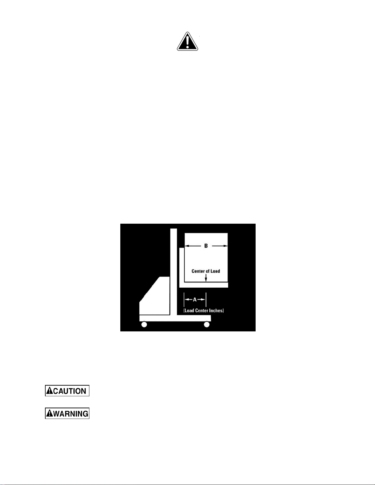
4. Do not exceed load center capacity of stacker. Load center is measured horizontally from back of forks or
platform. See Figure 1. The load center (A) is 20-inches on the JHS-2200A Stacker.
5. Overall length of load must never be more than twice the load center capacity.
6. Do not allow anyone to sit or ride on fork, or enter area beneath forks.
7. Always keep fingers, hands and feet clear of forks and mast when lowering load.
8. Always secure load before raising or moving the stacker.
9. Do not allow more than half of load to extend beyond load center of stacker.
10. Always keep load close to mast.
11. Do not transport load in raised position.
12. Use on level, smooth, finished floors only. Do not use on uneven or sloping floors.
13. Pull pump release lever slowly to allow load to descend in a controlled manner.
14. Always use genuine factory replacement parts only.
15. Failure to comply with all of these warnings may result in tipping, loss of control and load, damage to
hydraulic stacker, personal injury and/or property damage.
Figure 1
Familiarize yourself with the following safety notices used in this manual:
This means that if precautions are not heeded, it may result in minor injury and/or possible
machine damage.
This means that if precautions are not heeded, it may result in serious injury or possibly even
death.
4
Page 5

5.0 Specifications
Model number ............................................................................................................................... JHS-2200A
Stock number ...................................................................................................................................... 140531
Capacities and forces:
Load capacity ....................................................................................................................... 2200lb (998k g)
Pallet capacity .................................................................................................. 48” x 40” (1219 x 1016mm)
Load center ............................................................................................................................. 20” (508mm)
Maximum lift height ............................................................................................................... 62” (1575mm)
Minimum fork height .............................................................................................................. 2-3/4” (70mm)
Handle force required at maximum load ................................................................................... 85 lb (39kg)
Turning radius ............................................................................................................... 360°/50” (1 270mm)
Handle strokes to maximum height (no load / max. load) ................................................................ 44 / 86
Foot pedal strokes to maximum height (no load / max. load) ........................................................... 30 / 60
Dimensions:
Fork size ........................................................................... 42”L x 5-1/4”W x 2-1/4”H (1067 x 133 x 57mm)
Overall fork width (min./max.) .......................................................................... 11” / 27-1/2” (279 / 700mm)
Outrigger width .......................................................................................................................... 4” (102mm)
Outrigger height .................................................................................................................... 3-1/2” (90mm)
Outrigger inside width (min./max.) ........................................................... 34-1/4” / 50-1/2” (870 / 1283mm)
Outrigger outside width (min./max.) ................................................................... 42” / 58-3/4” (1067 / 1492)
Stacker overall size ............................................................. 62”L x 42”W x 78”H (1575 x 1067 x 1981mm)
Wheels:
Load wheel material and size ................................................ Black nylon / 5”OD x 3-1/4”W (127 x 83mm)
Caster material and size .........................................................Poly/Aluminum / 7”OD x 2”W (178 x 51mm)
Caster locks ............................................................................................................................................yes
Net weight ................................................................................................................................ 528 lb (240kg)
Shipping weight ........................................................................................................................ 558 lb (253kg)
The specifications in this manual were current at time of publication, but because of our policy of continuous
improvement, JET, reserves the right to change specifications at any time and without prior notice, without incurring
obligations.
5
Page 6

6.0 Setup and assembly
Number in parentheses refers to corresponding
number in parts breakdown.
1. Remove all packing material from stacker.
2. To assemble forks, remove one of the snap
rings (#5). Tap fork shaft out (#6). Forks to be
assembled must come from the same crate as
the mast.
3. Align holes in forks (#1) with holes in carriage
(#4) and tap fork shaft through carriage and
fork holes.
4. Reinstall snap ring (#5) to hold fork shaft in
place.
5. Be sure assembled forks are even and
parallel. Use adjusting screws (#3) if correction
is needed.
6. To assemble outrigger legs, make sure legs to
be assembled come from the same crate as
the mast.
7. Insert outrigger legs (#24A and #24B) into tube
openings in bottom of mast (#18). Align holes
in legs with holes in mast to enable legs to be
equal distance from mast. Legs should slide
into tube openings easily without force.
NOTE: Make sure the proper leg is inserted on
the correct side. (The beveled edge near the
wheel will face upward.) If the mast does not
stand vertical after assembling the legs, flip the
legs over and switch sides.
8. Fasten legs with four screws, four lock
washers four flat washers, and four hex nuts
(#25-27, and 33). Tighten hex nuts firmly.
9. IMPORTANT: The hydraulic cylinder comes
with a shipping plug installed (#106). Before
operating the stacker, remove this shipping
plug and install breather plug (included in
packaging provided with stacker) in its place.
Do not exceed rated load and
load center capacities. Excessive load can
cause tipping or loss of control. Use on
finished, smooth and level floors only; do not
use on slopes.
7.0 Operation
1. Insert both forks evenly and completely under
load. Load must be distributed equally on both
forks and centered toward the mast. Do not
allow more than half the load to extend beyond
load center. Do not lift load with fork tips only
and do not lift unstable or loose load.
2. Press the foot pedal or push the pump handle
downwards (handle lever must be in lower
position) to raise the forks by one stroke.
Continue to pump the pedal, or handle, until
desired height is reached. Do not exceed
maximum lifting height.
3. To lower forks, pull the pump release lever on
handle slowly to allow the load to lower in a
cautious and controlled manner.
4. To move stacker with load, lower forks
carefully. Use both hands with a firm grip to
push and steer the stacker on level, smooth
finished floors only. Keep all people clear from
stacker while lifting, lowering and moving load.
When not in use, do not allow
heavy loads to remain on the forks for an
extended period of time. Always lower forks
when not in use.
8.0 Maintenance
For optimum performance, the drive chain (#37)
should be lubricated with chain oil regularly.
Always store the hydraulic stacker without load,
and forks in lowest position.
Periodically check oil level in cylinder. Replenish as
needed with hydraulic jack oil through the oil plug
(#106)
Keep pivot points and metal-to-metal contact points
lubricated.
6
Page 7

9.0 Troubleshooting JHS-2200A Hydraulic Stacker
Number in parentheses refers to corresponding number in parts breakdown, section 10.1.1
Trouble Probable Cause Remedy
Fork will not lift to
maximum height.
Fork will not rise.
Fork cannot be
lowered.
Hydraulic fluid leak.
Hydraulic oil level is low. Fill with hydraulic oil.
Oil level is low, or oil is too viscous. Fill with oil, or change oil.
Oil has impurities. Change oil.
Hex nut (#62) is too high, keeping the
pumping valve open.
Air in hydraulic pump.
The lifting piston is deformed, resulting
from overloading.
The fork was kept in high position for
extended period, resulting in rusting
and jamming of the exposed piston rod.
Adjustment nut (#62) not in correct
position.
Fork frame and roller sprocket are
jammed.
Sealing parts worn or damaged. Replace parts.
Some parts cracked or worn. Replace parts.
Adjust hex nut properly.
Release air from system by pulling up
pump release lever, then pumping
handle up and down several times.
Replace piston.
Keep fork in lowest position when not in
use. Keep piston well lubricated.
Adjust nut properly.
Correct jam; replace bearing if
necessary.
The fork descends
without the release
valve working.
Release valve unable to close properly
due to impurities in hydraulic oil.
Hydraulic system cracked or bored. Inspect and replace the waste parts.
Air in the oil.
Seal parts worn or damaged in
hydraulic pump.
Adjustment nut (#62) not in correct
position.
Replace with new oil.
Release air from system by pulling up
pump release lever, then pumping
handle up and down several times.
Replace worn or damaged parts.
Adjust nut properly.
10.0 Replacement Parts
To order parts or reach our service department, call 1-800-274-6848 Monday through Friday (see our website
for business hours, www.jettools.com). Having the Model Number and Serial Number of your machine available
when you call will allow us to serve you quickly and accurately.
7
Page 8

10.1.1 JHS-2200A Mast Assembly – Exploded View
8
Page 9

10.1.2 JHS-2200A Mast Assembly – Parts List
Index No Part No Description Size Qty
1 ................ JHS2200-1 ................ Fork.......................................................................... ...................................... 2
3 ................ JHS1100-2 ................ Adjusting Screw ....................................................... ...................................... 2
4 ................ JHS2200A-4 .............. Mounting Plate ......................................................... ...................................... 1
5 ................ JHS2200A-5 .............. Snap Ring ................................................................ 30mm ............................ 6
6 ................ JHS2200A-6 .............. Fork Shaft ................................................................ ...................................... 1
7 ................ SB-14MM .................. Steel Ball.................................................................. 14mm ............................ 4
8 ................ JHS2200A-8 .............. Steel Ball Housing ................................................... ...................................... 4
9 ................ JHS2200A-9 .............. Snap Ring ................................................................ 62mm ............................ 4
10 .............. BB-6206ZZ ................ Ball Bearing ............................................................. 6206-2Z ........................ 4
11 .............. JHS2200A-11 ............ Guide Roller ............................................................. ...................................... 4
12 .............. JHS1100-13A ............ Rubber G rip Handle ................................................. .............. ........................ 2
13 .............. TS-1551041 .............. Lock Washer ............................................................ 6mm ............................ 16
14 .............. TS-1503021 .............. Socket Head Cap Screw ......................................... M6x10 ......................... 16
15 .............. TS-1551061 .............. Lock Washer ............................................................ 8mm .............................. 2
16 .............. TS-1504011 .............. Socket Head Cap Screw ......................................... M8x10 ........................... 2
17 .............. JHS2200-17 .............. Bar ........................................................................... ...................................... 1
18 .............. JHS2200-18 .............. Mast ......................................................................... ...................................... 1
19 .............. JHS1100-17 .............. Snap Ring ................................................................ 20mm ............................ 4
20 .............. JHS2200-20 .............. Front Wheel Axle ..................................................... ...................................... 2
21 .............. JHS1100-18 .............. Dust Cap .................................................................. ...................................... 8
22 .............. BB-6204ZZ ................ Ball Bearing ............................................................. 6204-2Z ...................... 10
23 .............. JHS1100-20 .............. Front Wheel ............................................................. ...................................... 2
24A ............ JHS2200-24A ............ Left Outrigger Leg .................................................... ...................................... 1
24B ............ JHS2200-24B ............ Right Outrigger Leg ................................................. ...................................... 1
25 .............. TS-154010 ................ Hex Nut .................................................................... M16 ............................... 4
26 .............. TS-155110 ................ Lock Washer ............................................................ 16mm ............................ 4
27 .............. JHS2200A-27 ............ Hex Head Bolt.......................................................... M16x140 ....................... 4
28 .............. TS-1550031 .............. Flat Washer ............................................................. 5mm .............................. 6
29 .............. TS-1551031 .............. Lock Washer ............................................................ 5mm .............................. 6
30 .............. TS-1502031 .............. Socket Head Cap Screw ......................................... M5x12 ........................... 6
31 .............. JHS2200-31 .............. Steel Fence ............................................................. ...................................... 1
32 .............. TS-2310181 .............. Hex Nut .................................................................... M18 ............................... 4
33 .............. TS-155010 ................ Flat Washer ............................................................. 16mm ............................ 4
34 .............. JHS1100-35 .............. Chain ....................................................................... 05B-1x15mm ................ 2
35 .............. JHS1100-59 .............. Chain Wheel ............................................................ ...................................... 2
36 .............. JHS1100-11 .............. Snap Ring ................................................................ 47mm ............................ 2
37 .............. JHS1100-60 .............. Chain W heel Brack et ............................................... ...................................... 1
38 .............. JHS1100-61 .............. Spring Pin ................................................................ Ø8x50mm ..................... 1
39 .............. TS-1503021 .............. Socket Head Cap Screw ......................................... M6x10 ........................... 1
40 .............. TS-1490051 .............. Hex Cap Screw ........................................................ M8x30 ........................... 2
41 .............. TS-1541031 .............. Nylon Lock Hex Nut ................................................. M8 ................................. 4
42 .............. JHS1100-65 .............. Roller ....................................................................... ...................................... 1
43 .............. JHS1100-42 .............. Foot Pedal ............................................................... ...................................... 1
44 .............. JHS2200A-44 ............ Rubber G rip ............................................................. ...................................... 1
45 .............. JHS2200A-45 ............ Clevis Pin ................................................................. 8x40mm ........................ 1
46 .............. JHS2200A-46 ............ Cotter Pin ................................................................. 2.5x12mm ..................... 1
47 .............. JHS1100-45 .............. Roller Pin ................................................................. ...................................... 1
48 .............. JHS1100-46 .............. Bushing .................................................................... 1715 .............................. 1
49 .............. JHS1100-47 .............. Roller ....................................................................... ...................................... 1
50 .............. JHS1100-51 .............. Roller Axle ............................................................... ......
51 .............. JHS2200A-51 ............ Spring Pin ................................................................ 4x10mm ........................ 2
52 .............. JHS1100-49 .............. Bushing .................................................................... 1608 .............................. 2
53 .............. JHS1100-50 .............. Foot Lever................................................................ ...................................... 1
54 .............. JHS2200A-54 ............ Snap Ring ................................................................ 16mm ............................ 3
55 .............. JHS1100-52 .............. Spring Pin ................................................................ Ø4x22mm ..................... 2
56 .............. JHS1100-53 .............. Roller ....................................................................... ...................................... 1
57 .............. JHS1100-54 .............. Lever ........................................................................ ...................................... 1
58 .............. JHS1100-55 .............. Spring Pin ................................................................ Ø6x30mm ..................... 1
.................. JHS2200A-RCA ........ Release Chain Assembly (includes #59 thru 61) ..... ...................................... 1
................................ 1
9
Page 10

Index No Part No Description Size Qty
59 .............. JHS2200A-59 ............ Release Rod ............................................................ ...................................... 1
60 .............. JHS2200A-60 ............ Chain ....................................................................... ...................................... 1
61 .............. JHS2200A-61 ............ Anchor Bolt .............................................................. ...................................... 1
62 .............. TS-1541011 .............. Nylon Lock Hex Nut ................................................. M5 ................................. 1
63 .............. JHS1100-56A ............ Handle ..................................................................... ...................................... 1
64 .............. JHS1100-57 .............. Blocking Spring ........................................................ ...................................... 1
65 .............. JHS2200A-65 ............ Spring ...................................................................... ...................................... 1
66 .............. JHS1100-58 .............. Spring Pin ................................................................ Ø4x30mm ..................... 3
67 .............. JHS1100-66 .............. Shaft ........................................................................ ...................................... 1
68 .............. JHS1100-64 .............. Handle Pin ............................................................... ...................................... 1
69 .............. JHS2200A-69 ............ Bushing .................................................................... 18x16x15mm ................ 2
70 .............. JHS2200A-70 ............ Ball Bearing ............................................................. 32906 ............................ 2
71 .............. BB-6005 .................... Ball Bearing ............................................................. 6005 .............................. 2
72 .............. JHS2200A-72 ............ Hex Nut ................................................................... M18 ............................... 4
73 .............. JHS2200A-73 ............ Dust Cap .................................................................. ...................................... 2
74 .............. JHS1100-75 .............. Foot Brake ............................................................... ...................................... 2
75 .............. JHS1100-76 .............. Stop Lug .................................................................. ...................................... 2
76 .............. TS-1550061 .............. Flat Washer ............................................................. 8mm .............................. 4
77 .............. JHS2200A-77 ............ Anchor Bolt .............................................................. ...................................... 2
78 .............. JHS2200A-78 ............ Hex Cap Screw ........................................................ M14x15 ......................... 4
79 .............. TS-2361141 .............. Lock Washer ............................................................ 14mm ............................ 4
80 .............. TS-155009 ................ Flat Washer ............................................................. 14mm ............................ 4
81 .............. JHS1100-83N ............ Wheel Axle............................................................... ...................................... 2
82 .............. JHS1100-85N ............ Wheel....................................................................... ...................................... 2
83 .............. JHS1100-44 .............. Spring Pin ................................................................ Ø3x30mm ..................... 1
84 .............. JHS1100-63 .............. Shaft ........................................................................ ...................................... 1
85 .............. JHS1100-69 .............. Spring ...................................................................... ...................................... 1
129 ............ TS-1540081 .............. Hex Nut .................................................................... M12 ............................... 4
130 ............ TS-1492051 .............. Hex Cap Screw ........................................................ M12x50 ......................... 4
131 ............ JHS2200A-131 .......... Bushing .................................................................... ...................................... 2
132 ............ JHS1100-72A ............ Wheel Cover ............................................................ ...................................... 2
.................. PT2748J-JET ............ JET Logo Label ....................................................... 2-5/8” x 7-1/2” ............... 2
.................. JHS2200A-ID ............ ID/Warning Label ..................................................... ...................................... 1
.................. JWS-FW .................... Fork W arning Label ................................................. ...................................... 2
.................. JWS-LCW ................. Load Center Warning Label ..................................... ...................................... 1
10
Page 11

10.2.1 JHS-2200A Pump Assembly – Exploded View
11
Page 12

10.2.2 JHS-2200A Pump Assembly – Parts List
Index No Part No Description Size Qty
.................. JHS2200A-PA ........... Pump Assembly (includes #86-133) ........................ ........................................
86 .............. JHS1100-86 .............. Bolt........................................................................... ...................................... 1
87 .............. JHS1100-87 .............. Spring Cap ............................................................... ...................................... 1
88 .............. JHS1100-88 .............. Spring ...................................................................... ...................................... 1
89 .............. JHS1100-89 .............. Dust Seal * ............................................................... 20x28x6mm .................. 1
90 .............. JHS1100-90 .............. U-Ring * ................................................................... 20x28x5mm .................. 1
91 .............. JHS1100-91A ............ Pump Housing (serial # 12040001 and higher) ....... ...................................... 1
.................. JHS1100-91 .............. Pump (serial # previous to 12040001) ..................... ...................................... 1
92 .............. JHS2200A-92 ............ Plunger Pis ton ......................................................... ...................................... 1
93 .............. SB-4MM .................... Steel Ball.................................................................. 4mm .............................. 2
94 .............. JHS1100-96 .............. Spring ...................................................................... ...................................... 1
95 .............. JHS1100-95 .............. Adjusting Screw ....................................................... ...................................... 2
96 .............. JHS1100-94 .............. Spring ...................................................................... ...................................... 1
97 .............. JHS1100-98 .............. Back-Up Ring * ........................................................ 18x24x1.25mm ............. 1
98 .............. JHS1100-99 .............. U-Ring * ................................................................... 18x25x5mm .................. 1
99 .............. JHS1100-110 ............ Washer * .................................................................. ...................................... 1
100 ............ JHS1100-111 ............ Dust Seal * ............................................................... 32x40x5.5mm ............... 1
101 ............ JHS1100-112 ............ Cover ....................................................................... ...................................... 1
102 ............ JHS1100-113 ............ O-Ring * ................................................................... 63x3.55mm ................... 1
103 ............ JHS1100-114 ............ O-Ring * ................................................................... 31.5x3.55mm ................ 1
104 ............ JHS1100-115 ............ U-Ring * ................................................................... 32x40x5.5mm ............... 1
105 ............ JHS1100-116 ............ Ram Piston .............................................................. ...................................... 1
106 ............ JHS1100-117 ............ Oil Plug .................................................................... M8x10 ........................... 1
107 ............ JHS2200A-107 .......... Pump Body .............................................................. ...................................... 1
108 ............ SB-6MM .................... Steel Ball.................................................................. 6mm .............................. 2
108A .......... SB-7MM .................... Steel Ball.................................................................. 7mm .............................. 1
109 ............ JHS1100-120 ............ Spring Base ............................................................. ...................................... 1
110 ............ JHS1100-121 ............ Spring ...................................................................... ...................................... 1
111 ............ JHS1100-122 ............ Adjusting Screw ....................................................... ...................................... 1
112 ............ PT2748J-101B-8 ....... O-Ring * ................................................................... 11.8x2.65mm ................ 1
113 ............ JHS1100-123 ............ Relief Plug ............................................................... ...................................... 1
114 ............ JHS2200A-114 .......... Bushing .................................................................... ...................................... 1
115 ............ JHS2200A-115 .......... Spring ...................................................................... ...................................... 1
116 ............ JHS2200A-116 .......... Valve Stem .............................................................. ...................................... 1
117 ............ JHS1100-107 ............ O-Ring * ................................................................... 13.2x2.65mm ................ 2
118 ............ JHS2200A-118 .......... Valve Housing ......................................................... ...................................... 1
119 ............ TS-1540061 .............. Hex Nut .................................................................... M8 ................................. 1
120 ............ JHS2200A-120 .......... Coupler .................................................................... ...................................... 1
121 ............ JHS2200A-121 .......... Spring ...................................................................... ...................................... 1
122 ............ JHS2200A-122 .......... Valve Stem .............................................................. ...................................... 1
123 ............ JHS2200A-123 .......... O-Ring * ................................................................... 7.5x1.8mm .................... 2
124 ............ JHS2200A-124 .......... O-Ring * ................................................................... 19x2.65mm ................... 1
125 ............ JHS2200A-125 .......... Release Plug ........................................................... ...................................... 1
126 ............ JHS2200A-126 .......... Cam ......................................................................... ...................................... 1
127 ............ JHS1100-43A ............ Spring Pin ................................................................ Φ8x45mm ..................... 1
128 ............ JHS2200A-128 .......... Screw ....................................................................... M8x50 ........................... 1
133 ............ JHS2200A-133 .......... O-Ring * ................................................................... 5.7x1.9mm .................... 2
.................. JHS2200A-RK ........... Pump Repair Kit (includes items marked with *)...... .............................
...........
12
 Loading...