

Page 1

OWNER'S MANUAL
JDS-12B Benchtop 12” Disc Sander
(708432K shown with optional stand 708438 and Canister Filter 708434)
JET P.O. BOX 1349 Phone: 253-351-6000
WMH Tool Gr oup Auburn, W A 98071- 1349 Fax: 1-800-274-6840
www.wmhtoolgroup.com e-mail jet@wmhtoolgroup.com M-708433 05/02
Page 2

This manual has been prepared for t he owner and operators of a JDS-12B Sander . Its purpose, aside
from machine operation, is to promote safety through the use of accepted correct operating and
maint enance procedures. Completely r ead the safety and m aintenance i nstructions bef ore operati ng or
servi cing the mac hine. To obtai n maxi mum life and effic iency from your JET Sander, and to aid in using
the machine safely, r ead this manual thoroughly and f ollow instructions carefully.
Warranty & Service
The WMH Tool Gr oup warrant s every product it sells. If one of our tools needs servic e or r epair, one of
our Authorized Repair Stations located throughout the United St ates can give y ou quick serv ice.
In most cases, any one of these W M H Tool Group Repai r S tations can authorize warranty repair, assist
you in obtai ning parts, or perform rout ine maint enanc e and major repair on your JET, P erform ax, Wilt on,
or Powermatic tools.
For the nam e of an Authorized Repair Stat ion in your area, please call 1-800-274- 6848, or visit
www.wmhtoolgroup.com
More Information
Remember , the WMH Tool Group is consistently adding new products to the li ne. For complete, up-todate product i nformation, check with your local WMH T ool Group distributor, or visit
www.wmhtoolgroup.com
WMH Tool Group Warranty
The WMH Tool Gr oup ( including P er formax, Wilton and P owermatic brands) makes every effort to
assure that its product s meet high quality and durability standards and war r ants to the origi nal retail
consumer/purc haser of our products that each product be fr ee from defects in materials and
workmanship as follow: 1 YEAR LIMI T E D WARRANTY O N ALL PRO DUCTS UNLESS SPECIFIED
OTHERWISE. This War r anty does not apply to defects due direct ly or indi r ec tly to m isuse, abuse,
negligence or accidents, normal wear-and-tear, r epair or alter ations outside our f ac ilities, or to a lack of
maintenance.
THE WMH TO O L GROUP LIMIT S ALL IMPLIED WARRANTIES TO THE PERIOD SPECIFIED ABOVE,
FROM THE DATE THE PRODUCT WAS PURCHASED AT RETAIL. EXCEPT AS STATED HEREIN,
ANY IMPLIED WARRANTIES OR MERCHANTIBILITY AND FITNESS ARE EXCLUDED. SOME
STATES DO NOT ALLOW LIMITATIONS ON HOW LONG THE IMPLIED WARRANTY LASTS, SO
THE ABOVE LIMITATION MAY NOT APPLY TO YOU. T HE WMH TOOL GROUP SHALL IN NO
EVENT BE LIABLE FOR DEATH, INJURIES TO PERSONS OR PROPERTY, OR FOR INCIDENTAL,
CONTINGENT, SPECIAL, OR CONSEQUENTIAL DAMAGES ARISING FROM THE USE OF OUR
PRODUCTS. S OME STATES DO NOT ALLOW THE EXLUSION OR LIMITA TION OF I NCIDENTAL
OR CONSEQUENTIAL DAMAGES, SO THE ABOVE LIMITATION OR EXCLUSION MAY NOT APPLY
TO YOU.
To take advantage of this warranty, the produc t or part must be returned for examinat ion, postage
prepaid, to an A uthorized Repair S tation designated by our office. Proof of purchase date and an
explanat ion of the c omplaint must accompany the merchandise. If our i nspect ion discloses a defect, we
will either repair or replace the product, or refund the purchase pric e if we cannot readily and quickly
provide a repair or replacement, if you ar e willing to accept a refund. We will return repai r ed product or
replacement at JET’S expense, but if it i s deter mined there is no defect, or that the defec t resulted f r om
causes not within the scope of JET’S warranty, then the user must bear t he c ost of storing and ret ur ning
the product. This warranty gives you specif ic legal rights; you may also have other rights which vary
from state to state.
The WMH Tool Gr oup sel ls through distri butors only. Mem ber s of the WMH Tool Gr oup r eserve the
right to effec t at any time, without prior notice, those alterati ons to par ts, fittings, and accessory
equipment whi c h they may deem nec essary for any reason whatsoever.
2
Page 3

WARNING
Wear eye protection.
Always keep guards in place an d in prop er operating condition. Do not operate the machine
without the guards for any reason.
This disc sander is intended to be used with wood and wood products only. Use of this disc
sander and a dust collector with metal products is a potential fire hazard.
Support the workpiece adequately at all times during operati on; maintai n control of the work at
all times.
This disc sander is designed and intended for use by properly trained and experienced
personnel only. If you are not familiar with the proper and safe operation of a disc sander, do
not use until proper training and knowledge has been obtained.
• REMOVE ADJUSTING KEYS AND WRENCHES. Form a habi t of checking to see that keys and
adjusting wrenches are removed from the machine before turning it on.
• KEEP THE WORK AREA CLEAN. Cluttered areas and benches invite accidents.
• DON’T US E IN A DANGEROUS ENVIRONMENT. Don’t use power tools in damp or wet locati ons,
or expose them to rain. Keep work area well light ed.
• KEEP CHILDREN AWAY. Al l visitors should be kept a saf e distance from the work area.
• MAKE THE WORKSHO P KIDPROOF with padlocks, master swatches, or by r emoving starter keys.
• DON’T FORCE THE M ACHINE. It will do the job better and safer at the rate for which i t was
designed.
• USE THE RIGHT TOOL. Don’t force a machine or attachment to do a job for which it was not
designed.
• USE THE PROPER EXTENSION CORD. Make sure your extension cord is in good condition.
When usi ng an extension cord, be sure t o use one heavy enough to carr y the current your machine
will draw. An under sized cord will cause a drop in the line voltage resulting in power loss and
overheating. The t able following shows the correct size to use depending on the cord length and
nameplat e ampere rati ng. If i n doubt, use the next heavier gauge. Remember , the small er the
gauge number, t he heavier the cord.
Volts Total Length of Cord in Feet
120V 25 50 100 150
16 16 14 12
• WEAR PROPER APPAREL. Do not wear loose clothing, gloves, neckties, rings, bracelets, or other
jewelry which may get caught i n mov ing parts. Nonslip footwear is recom mended. Wear protective
hair covering to c ontain long hair .
• ALWAYS USE SAFETY GLASSES. Also use face or dust masks if the c utting operation is dusty.
Ever y day eyeglasses only have impact r esi stant lenses; they are not safety glasses.
• DON’T OVERREACH. Keep proper f ooting and balance at all ti mes.
• MAINTAIN T OOLS WITH CARE. Keep tools sharp and clean for best and safest performance.
Follow i nstr uc tions for l ubricating and c hanging accessories.
AWG
3
Page 4

• ALWAYS DISCONNECT THE MACHINE FROM THE POWER SOURCE BE FORE SERVICI NG.
• REDUCE THE RISK OF UNINTENTIONAL STARTING. Make sure the switch is i n the off position
before pl ugging in.
• USE RECOMMENDED ACCESSORIES. The use of acc essories and attachments not
recommended by JET m ay c ause hazards or r isk of injury to persons.
• NEVER STAND ON A MACHINE. Serious injury could occur if the machine is tipped.
• CHECK DAMAGED PARTS. Before furt her use of the machine, a guard or other part that is
damaged should be carefully c hec k ed to determine that it will operate properly and perf or m its
intended function - chec k for ali gnment of moving parts, binding of moving parts, breakage of parts,
mounti ng, and any other conditions that may affec t its operation. A guard or other part that is
damaged should be properly repaired or replaced.
• NEVER LEAVE THE MACHINE RUNNING UNATTENDED. TURN PO WER O F F. Don’t leave the
machine until i t comes to a com plete stop.
• SOME DUST CREATED by power sanding, sawing, grinding, drilling and other construction activities
contains chemicals known to cause cancer, birth defec ts or other reproductive harm. Some
examples of these chem icals are:
• Lead from lead based paint
• crystalline silica from bricks and cement and other masonry products, and
• arsenic and chromium from chemically-treated lumber.
• Your risk from those ex posures varies, dependi ng on how often you do this ty pe of work. To reduce
your exposure to these chemical s: work in a well ventilated area, and work with approved safety
equipment , such as those dust masks that are specifically designed to filter out microscopi c par ticles
• DO NOT oper ate tool while under the influence of drugs, alcohol or any m edication.
• AVOID kickback by sanding in accor danc e with directional arrows. Sand on downward side of disc.
Sanding on the upward side could cause the workpiece to fly up causing i njury.
• SAND with the grain of the wood.
• DO NOT sand pi ec es of material that are too small to be safely supported.
• WHEN sanding a lar ge workpiece, provide additional support at t able height.
• ADDITIONAL INFORMATION regarding the safe and proper oper ation of t his product is available
from the National Safety Counc il, 1121 Spring Lake Drive, Itasca, IL 60143-3201, in the Accident
Prev ention Manual for Industrial Operati ons and al so i n the safety Data Sheets provi ded by the NSC.
Please also refer to the Am er ican National Standards Institute ANSI 01.1 Safety Requirements for
Woodworking Machinery and t he U.S. Departm ent of Labor OS HA 1910.213 Regulations.
• SAVE THESE INSTRUCTIONS refer to them often and use them to instruct others.
4
Page 5
Grounding Instructions
Caution: This tool must be grounded while in use to protect the operator from electric shock.
In the event of a malf unc tion or breakdown, groundi ng pr ovides a path of least resistance for electric
current to r educ e the risk of electric shock. This tool is equipped with an elect r ic cord having an
equipment -grounding conductor and a gr ounding plug. The plug must be plugged into a matc hing outlet
that is properly installed and grounded in accordance with all local codes and ordinances.
Do not modi fy the pl ug pr ovided. If it will not fit the outlet, have the proper outlet installed by a qualified
electrician.
Improper connection of the equipment-grounding conduct or c an r esul t in a risk of electric shock. The
conductor, with insulation having an out er surface that is green with or without yellow stripes, is the
equipment -grounding conductor. If repair or replacement of t he electric c or d or plug is necessary, do not
connect the equi pment-groundi ng c onduc tor to a li ve terminal.
Check with a qualified electrician or service personnel if the grounding instructions are not c ompletel y
understood, or if in doubt as to whether t he tool is properl y gr ounded. Use only three wire extension
cords that have three-prong grounding plugs and three-pole r ec eptacles that accept the tool’s plug.
Repair or replace a damaged or worn cord immedi ately.
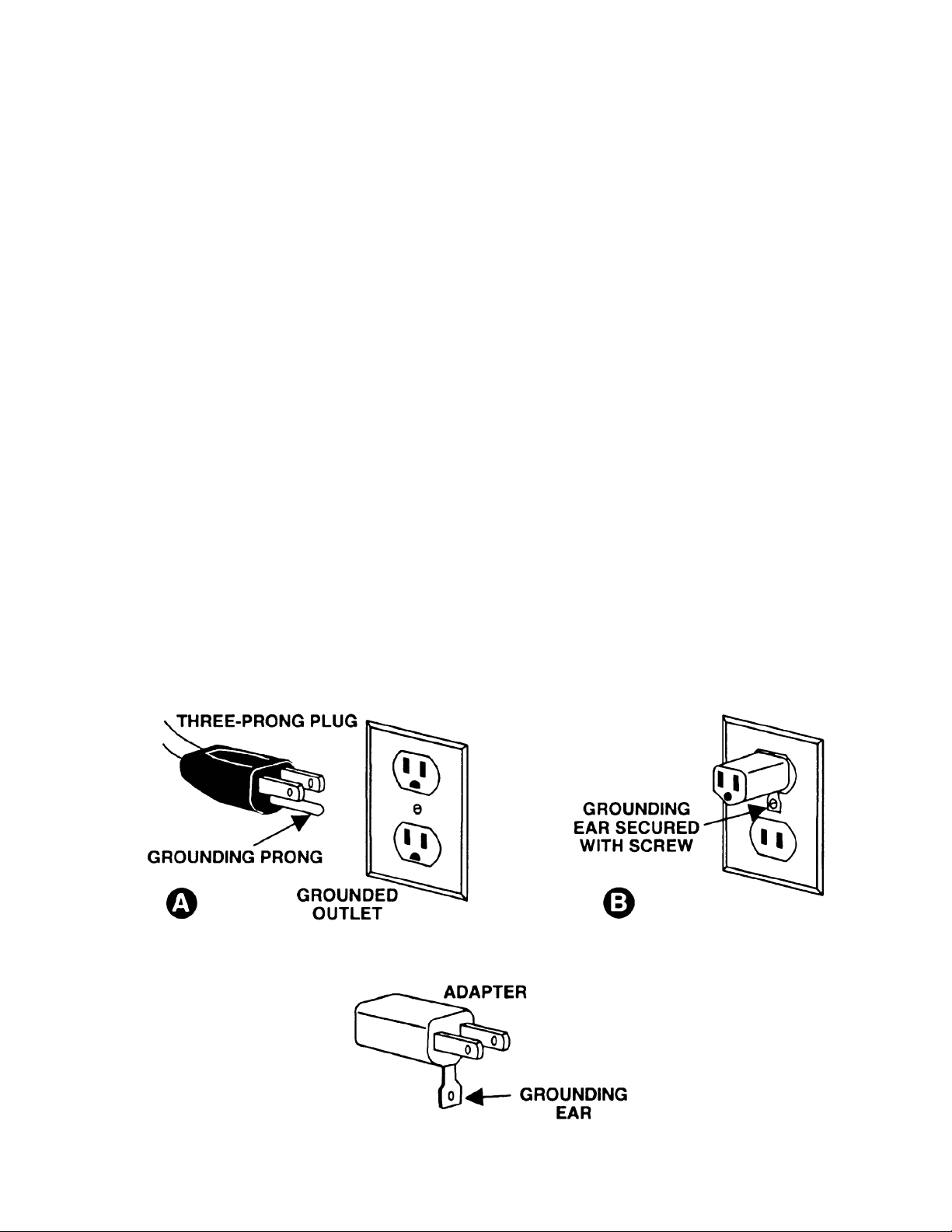
115 Volt Operation
As received from the factory, your sander is ready to run at 115 volt operation. This sander, when wired
for 115 volt, is intended for use on a circuit that has an outlet and a plug that look s l ike the one illustrated
in (A). A temporary adapter, which looks l ike the adapter as illustrated in (B), may be used to connect
this plug to a two-pole receptacl e, as shown in (B) if a proper ly grounded outlet is not av ailable. The
temporary adapter should only be used until a properly gr ounded outlet can be inst alled by a qualified
electrician. T his adapter is not applicable in Canada. The green colored rigid ear, lug, or tab,
extendi ng from the adapter, must be c onnec ted to a permanent gr ound such as a properly grounded
outlet box, as shown in (B).
5
Page 6
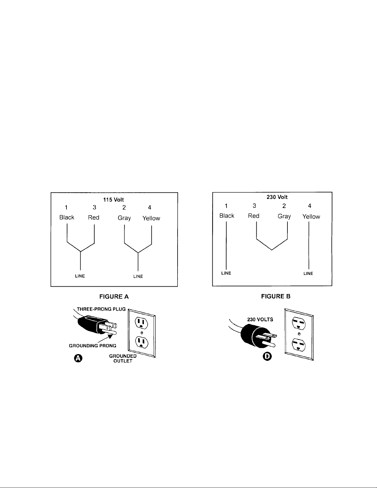
230 Volt Operation
If 230V, single phase operation is desired, the following instr uc tions must be followed:
1. Disconnect the machine from the pow er source.
2. This JET sander is supplied with four motor leads that ar e c onnec ted for 115V operation, as shown in
Figure A. Reconnect these four motor leads for 230V operation, as shown in Figure B.
3. The 115V attachment plug (A), supplied with the sander, must be replaced wit h a UL/CSA listed plug
suitable for 230V operati on ( D) . Contact your local Authorized JET Service Cent er or qualified
electrician f or pr oper pr oc edures to install the plug. The sander must comply with all l oc al and
national c odes after the 230 volt plug is installed.
4. The sander with a 230 v olt plug should onl y be c onnected to an outlet havi ng the same configuration
(D). No adapter is available or should be used with the 230 volt plug.
Important: In all c ases (115 or 230 volts), make certain the receptacl e in question is properly grounded.
If you ar e not sure, have a r egistered electr ician check t he r eceptacle.
6
Page 7

Specifications JDS-12B
Stock Number................................................................................................................................708433
Disc Diameter.......................................................................................................................................12”
Table Tilt......................................................................................................................15° Up - 45° Down
Dust Chute Diameter..............................................................................................................................4”
Disc Tabl e .................................................................................................................16-3/8" W x 9-3/4” D
Motor..............................................................................................................1 HP, 115/230V, 60Hz, 1P h
Impeller.................................................................................................................................9” x 1-13/16”
Overall Dimensions...........................................................................................21” W x 25-5/8" D x 21” H
Net Weight (approx.) ....................................................................................................................100 Lbs.
Table of Contents
Warranty .................................................................................................................................................2
Warnings ....................................................................................................................... .......................3-4
Grounding Instructions.............................................................................................................................5
115V Operati on .......................................................................................................................................5
230V Operati on .......................................................................................................................................6
Specifications..........................................................................................................................................7
Table of Contents....................................................................................................................................7
Contents of the Shipping Carton..............................................................................................................8
Tools Required for Assembly & A djustment .............................................................................................8
Unpacking ...............................................................................................................................................8
Stand Assembly ( optional accessory).......................................................................................................9
Sander Assembly.....................................................................................................................................9
Table Adjustment...................................................................................................................................10
Sanding Disc Replacement....................................................................................................................10
Center Point ..........................................................................................................................................11
Brake.....................................................................................................................................................11
On/Off Switch........................................................................................................................................11
Lubrication.............................................................................................................................................11
Motor.....................................................................................................................................................11
Dust Collection ......................................................................................................................................11
Canister Filter (optional accessory)........................................................................................................12
Cleaning the fil ter............................................................................................................................12
Optional Accessories.............................................................................................................................12
Troubleshooting.....................................................................................................................................13
Parts Breakdowns & Parts List..........................................................................................................14-17
Wiring Diagram .....................................................................................................................................18
The specif icat ions in thi s manual are giv en as general inf ormat ion and are not bindi ng. T he W MH Tool
Group reserves the right to ef fect, at any tim e and without prior notice, changes or alt erations to parts,
fittings, and accessory equipment deemed nec essary for any reason whatsoever.
7
Page 8

Contents of the Shipping Carton
JDS-12B Benchtop Sander
1. Sander
1. Sanding Disc
1. Table
1. Miter Gauge
1. Inlet
1. Inlet Gasket
1. Owner's Manual
1. Warranty Card
Hardware Kit
4. Hex Head Bolt M 10x40
8. Flat Washer M10
4. Lock Washers M10
4. Hex Nut M10
4. Hex Head Bolt M 6x16
1. Center Point
1. Right Angle Hex W r enc h 3mm
1. Filler Bar
1. Socket Head Cap Screw M5x 8
OS-12DS Stan d (optional accessory)
4. Stand Legs
4. Stand Supports
Hardware Kit
16. Carr iage Bolt M8x16
16. Hex Nut M8
CF-12DS Canist er Filter (optional accessory)
1. Canister Filter
1. Plastic Elbow
1. Grounding Wire
Tools Required for Assembly &
Adjustments
1. 13mm Wrench or socket
1. Combination Square
(708432K shown with optional stand 708438 and
Canister Filter 708434)
WARNING
Read and understand the entire contents of
this manu al before attemp t ing assembly or
operation of the disc sander!
Failure t o comply may cause serious inj ury!
Unpacking
1. Remove all contents from the shipping
carton(s).
2. Report any damage to your distri butor.
3. Do not discard any shipping material until
the sander has been assembled and is
running properly.
8
Page 9

Stand Assembly (optional accessory)
1. Match the hole patterns in the stand legs
with the hole patterns in the stand supports.
Mount the legs to the outside of the supports
using sixteen M8x16 carriage bolts and
sixteen M8 flange lock nuts, figure 1. Do
not tighten until the stand has been
assembled and is sitting level on the floor.
2. Bolt the sander to the stand with four
M10x40 hex cap bolts, eight M10 flat
washers, four M10 lock washers and four
M10 hex nuts
Sander Assembly
1. Mount the sander to JET’s open stand with
four M10x40 hex head bolts, eight M10 flat
washers, four lock washers, and four hex
nuts. Tight en the nuts t o secure the sander
to the stand.
Note: If you are going to use the sander as
a benchtop unit mount the sander to the
workbench with the suppli ed bolts.
2. Unscrew the knob (A, Fig. 2), remove the
washer (B, Fig. 2) and the trunnion holder
(C, Fi g. 2). Repeat f or opposi te side.
3. Lift the t able ( D, F i g. 2) i nt o positi on and set
on top of t he spl it pins and threaded shaft.
4. Reinstall the trunnion holder, washer and
knob. Repeat for opposite side.
5. Make sure the trunni on and trunnion holder
engage and tighten t he k nob.
6. Place the gasket (E, Fig. 3) against the
sander base and mount the i nlet port (F, Fi g.
3) to the sander with four M6x16 hex cap
bolts (G, Fig. 3).
Warning
Avoid kickback by sanding in accordance
with directional arrow. Sand on downward
side of disc. Sanding on the upward side
could cause the workp iece to fly up causing
injury! Failure to comply may cause serio us
injury!
9
Page 10

Table Adjustment
The table stops have been set-up at the f ac tory .
However, if you run into a problem, or want to
check the table follow the below listed steps.
1. Loosen lock knobs (B, Fig. 4) and mov e t he
table to the 90 degree position. Tighten
knobs and place a square (A, Fig. 4) agai nst
the table and di sc. The square should rest
flat against the table and disc.
2. If adjustment is needed move the table so
that it rests 90 degrees from the table, and
loosen the hex nut (D, Fig. 5) and tighten
the set screw (C, Fig. 5) unti l it cont acts t he
table surface. Tighten hex nuts. This will
properly adjust the 90-degree stop.
3. Loosen t he l ock knobs (F , F ig. 5) and t i lt the
table up just enough to pivot the stop (E, Fig.
5) out of the way.
4. Ti lt the table down until it hi ts the 45 degree
stop (G, Fig. 5). Tighten lock knobs, and
check the table with a combination square.
5. If adjustm ent is needed, loosen the hex nut
(H, Fig. 5) and adjust the socket head cap
screw (G, Fig. 5) unt il it contac ts the table.
Tighten hex nuts.
6. Always maintain a gap of approximately
1/16” between the table edge, and disc. If
adjustment is necessary loosen hex cap
bolts (I, Fig. 5) and move the table into
position. Tighten hex c ap bolts.
7. The table tilts between 15° up - 45° down by
loosening the lock knobs and tilting the table
to the desired angle. Tighten the knobs.
8. If you want to tilt the table up you need to
pivot the stop (E, Fig. 5) out of the way.
Sanding Disc Replacement
1. Disconnect machine from the power
source.
2. Remov e the knobs (J, Fig. 6), washers (K,
Fig. 6), and trunnion holders (L, Fig. 6)
followed by the table assembl y ( M , Fig. 6).
3. Remove old sanding disc by striping from
wheel. Use a cleaner and putty knife to
remove the residue. Make sure the disc
plate is clean and dry.
4. Press the new disc firmly int o place.
10
Page 11

Center Point
The center point (A, Fig. 7) provided with the
sander can be used for sanding circles. Slide
the center point into the miter slot that is
perpendicular to the sanding disc. The radi us of
the desired circle should be the distance from
the center point to the sanding disc. Lock the
center point in position by tightening the set
screws. Cut the wood to the approximate
diameter and press on to the center point.
Rotate the wood until the desired results are
achieved.
Filler Bar
The f iller bar (H, Fig. 7) should be added when
sanding small workpieces. Secur e in pl ace with
the socket head cap screw (I, Fi g. 7) . When not
using the filler bar thread the socket head cap
screw (I, Fig. 7) in the tapped hole as a stop.
Brake
After you have t urned t he sander “OF F” y ou can
press the brake (B, Fi g. 7) to slow, or stop the
sanding disc.
On/Off Switch
The machi ne can be t urned “O N” by m oving t he
switch (D, Fig. 8) to the “UP” posi tion. The k ey
(E, Fig. 8) can be r em ov ed when the m achi ne i s
in the “OFF” position. With the key removed
the switch will not operate.
Lubrication
You may need to lubricate the trunnion, and
trunnion hol der (G, Fig. 8) if the table does not
tilt smoothly.
Motor
Make frequent i nspecti ons of the m ot or f an c over,
and blow out (with low pressure air hose) or
vacuum any accumulation of foreign material in
order to maintain normal mot or ventilation.
WARNING
All electrical connections must be done by
a qualif ied electrici an. All adjust ments or
repairs must be done with the sander
disconnected from th e power source,
unplugged. Failure to comply may result in
serious injury!
The JDS-12B disc sander is rated 115V/230V,
Prewired 115V.
If you want t o run the JDS- 12B on 230V refer to
the wiring diagram found on the inside of the
switch box cover (F, Fig. 8).
Before hooking up to the power source, make
sure that the switch is in the off position.
Dust Collection
The disc sander has a built in f an designed to
suck the saw dust away from the sanding disc
and exhaust through the inlet (C, Fig. 7). For
best results hook the sander to JET’s optional
accessory canister filter (#708434).
The sander can also be attached to a dust
collector using a 4” diameter hose and clamp.
JET of fers a wide v ar iety of hoses, adapters and
dust collec tors.
11
Page 12

Canister Filter (optional accessory)
1. Remove the inlet port that came with the
sander.
2. Mount the plastic elbow (A, Fig. 9) to the
sander using the same hardware (B, F ig. 9)
from the inlet port.
3. Connect the filter (C, Fig. 9) to the elbow
and turn counter-cl ockwise so that i t loc ks in
place.
WARNING
Static electricity will build up in the filter
during operation. The filter ground must be
attached to the machine ground, and to the
filter. Failure to comply may result in
fire/loss of property, or personal injury!
4. Remove the screw (D, Fig. 9) from the
sander base. Attach the end of the
grounding wire to the screw and thread back
in to the base.
5. Attach the grounding clip (E, Fig. 9) to the
metal part of the filter. This will prevent
static electricity from building up in the filter .
Cleaning the Filter
CAUTION
Wearing a part icle mask/respirator for
protection against fine dust particles during
cleaning is highly recommended.
Clean the canister filter frequently to keep the
sander’s perform anc e at its optimum. T o c lean:
1. Disconnect the machine from th e power
source.
2. Take of f the gr ounding cli p and remov e t he
filter (C, F ig. 9) by turning clockwise.
3. Empty the contents into an appropriate
container.
4. The filter can be cleaned with a low
pressure air hose. Blow f rom t he outside of
the filter to clean the dust particles. For
best results check and empty the filter
frequently.
5. Install the filter and reattach the grounding
clip.
Optional Accessories
708438: Open Stand
708434: Canister Filter
57620025: JET St ik Abrasive Belt and Disc
Cleaner.
Dust Coll ect ors and Accessories see a JET
Distributor.
JDS-12B Sanding Disc PSA Aluminum Oxide
“J” Weight Cl oth Back.
12” 36 Grit 50 Grit 60 Grit
Stock
Number
Master
Carton
12” 80 Grit 100 Grit 120 Grit
Stock
Number
Master
Carton
57698525 57698650 57698750
25 50 50
57698850 57698950 57699050
50 50 50
12
Page 13

Troubleshooting
Trouble Possible Cause Solution
Sander will not start
Sanding disc does not come
up to speed
Machine vi brates excessively
1. Sander unplugged fr om wall
or motor
2. Fuse blown or circui t breaker
tripped
3. Cord damaged
1. Extension cor d too light or
too long
2. Low current
1. Stand or base on uneven
surface
1. Check all plug connections
2. Replace fuse or reset c ircuit
breaker
3. Replace cord
1. Replace with adequate siz e
and length cord
2. Contact a quali fied
electrician
1. Adjust stand or base so that
it rests evenly on the floor
2. Bolt down
Sanded edge not square
Sanding marks on wood
1. Table not square to sanding
disc
1. Work held still
2. Wrong grit sanding disc
3. Feed pressure too great
4. Sanding against the gr ain
1. Use a square to adjust table
to sanding disc
1. Keep workpiece moving
2. Use coarser grit f or stoc k
removal and fine grit for
finish sanding.
3. Never force workpiece
4. Sand with the grain
13
Page 14

Disc Sander Breakdown
14
Page 15

Parts List For The JDS-12B Benchtop Disc Sander
Disc Sander
Index Part
No. No. Description Size Qty
1..........612131......................... Guard Base........................................... ...............................................1
2..........MH612001 ...................Motor.....................................................1 HP, 1Ph 110V/220V............. 1
............ JDS12B-MFC............... Motor Fan Cover (not shown)................ ............................................... 1
............ JDS12B-MF.................Motor Fan (not shown)........................... ...............................................1
............ JDS12B-CS..................Centrifugal Switch (not shown)............... ............................................... 1
............ JDS12B-CC.................Capacitor Cover (not shown) ................. ...............................................1
............ JDS12B-JBC................ Junction Box Cover (not shown) ............ ...............................................1
............ JDS12B-SC..................Starting Capacitor (not shown)............... 200M FD, 125VAC.....................
............ JDS12B-RC.................Running Capacit or (not shown)..............10uF, 250V ...............................
3..........KS050565 .................... Key........................................................5x5x65....................................1
4..........994534......................... On/Off Switch........................................ ...............................................1
5..........998621......................... Strai n Relief........................................... ...............................................1
6..........IC100001 .....................Power Cord............................................ ...............................................1
7..........TS-1551071 ................. Spring Washer.......................................M8 ..........................................4
8..........SJ080400..................... Pan Head Socket Bolt............................ M8x20.....................................4
9..........612132......................... Fan Blade..............................................9”............................................1
10........ 612133......................... Parti tion................................................. ...............................................1
11........ SF069200 ....................Pan Head Bolt w/Flange........................M6x8.......................................5
12........ 612134......................... Sanding Disc......................................... ...............................................1
13........ SS060200 .................... Set Screw..............................................M6x8.......................................1
14........ 612113......................... Washer.................................................. ...............................................1
15........ SM089400.................... Countersunk Head Bolt..........................M8x16.....................................1
16........ 57698525.....................12” Disc Sandi ng P aper 36 Grit ............. .............................................25
............ 57698650.....................12” Disc Sandi ng P aper 50 Grit ............. .............................................50
............ 57698750.....................12” Disc Sandi ng P aper 60 Grit ............. .............................................50
............ 57698850.....................12” Disc Sandi ng P aper 80 Grit ............. .............................................50
............ 57698950.....................12” Disc Sandi ng P aper 100 Grit............ .............................................50
............ 57699050.....................12” Disc Sandi ng P aper 120 Grit............ .............................................50
17........ 612136......................... Front Cover ........................................... ...............................................1
18........ SF069200 ....................Pan Head Bolt w/Flange........................M6x8.......................................5
19........ TS-1504071 ................. Socket Head Cap Screw........................M8x35.....................................1
20........ TS-1540061 ................. Hex Nut.................................................M8 ..........................................1
21........ TS-1550061 ................. Fl at Washer...........................................M8x18.....................................1
22........ 612038......................... Trunnion Holder (A)............................... ...............................................1
23........ PS062600 .................... Spring Pin..............................................6x26........................................4
24........ SS081200 .................... Set Screw..............................................M8x60 .....................................2
25........ TS-1550061 ................. Fl at Washer...........................................M8x18.....................................2
26........ 612098......................... Knob...................................................... M8 ..........................................2
27........ 612052......................... Trunnion Holder (B)............................... ...............................................1
28........ 612135......................... Tabl e..................................................... ...............................................1
29........ 612046......................... Trunnion................................................ ...............................................2
30........ TS-1551061 ................. Lock Washer .........................................M8 ..........................................4
31........ TS-1490021 ................. Hex Head Bolt .......................................M8x16 .....................................4
32........ 612010......................... Locating Block....................................... ...............................................1
33........ PS053600 .................... Spring Pin..............................................5x36........................................1
34........ TS-1540041 ................. Hex Nut.................................................M6 ..........................................1
35........ TS-1523071 ................. Set Screw..............................................M6x25.....................................1
36........ 612116......................... Brake..................................................... ...............................................1
37........ 612118......................... Brake Fixed Base.................................. ...............................................1
38........ PS042600 .................... Spring Pin..............................................4x26........................................1
39........ SP040200 .................... Pan Head Bolt .......................................M4x10.....................................3
15
Page 16

Index Part
No. No. Description Size Qty
40........ 612140......................... Spri ng.................................................... ...............................................1
41........ WF051210...................Flat Washer...........................................M5x12.....................................1
42........ 612115......................... Stop Handle........................................... ...............................................1
43........ TS-1491061 ................. Hex Head Bolt .......................................M10x40...................................4
44........ TS-1550071 ................. Fl at Washer...........................................M10x20 ...................................8
45........ TS-1551071 ................. Lock Washer .........................................M10.........................................4
46........ TS-1540072 ................. Hex Nut.................................................M10.........................................4
47........ 612137......................... Packing ................................................. ...............................................1
48........ 612145......................... Inlet.......................................................4”............................................ 1
49........ TS-1482031 ................. Hex Head Bolt .......................................M6x16 .....................................4
50........ 612099......................... Sponge.................................................. ...............................................1
51........ TS-1551021 ................. Lock Washer .........................................M4 ..........................................2
52........ AB198101 .................... Miter Gauge Assembly .......................... ...............................................1
53........ AB612143 .................... Circle Gauge Assembly (A S M ) .............. ...............................................1
57........ 612117......................... Sponge Gasket ...................................... ...............................................1
58........ SP059200 .................... Pan Head Bolt .......................................M5x8.......................................1
59........ WE050000................... Star Washer..........................................M5 ..........................................1
60........ 612171......................... Filler Bar................................................ ...............................................1
61........ TS-1502011 ................. Socket Head Cap Screw........................M5x8.......................................1
* ..........JDS12B-HK.................. Hardware Kit (not shown)....................... .................................................
............ JDS12B-WL................. Warning Label (not shown).................... .................................................
............ JDS12B-ID................... I.D. Label (not shown)............................ .................................................
............ JDS12B-JL................... JET Label (not shown)........................... .................................................
Optio nal Accessory
54........ 612147......................... Elbow .................................................... ...............................................1
55........ 331022......................... Filter...................................................... ...............................................1
56........ 331033......................... Grounding Clip ...................................... ...............................................1
16
Page 17

Open Stand Breakdown (optional accessory)
JDS-12B Stand Assembly (optional accessory)
Index Part
No. No. Description Size Qty.
1..........612141............................. Stand Leg ...................................................... ...................................4
2..........612142............................. Stand Support ............................................... ...................................4
3..........SC089400........................ Carriage Bolt ................................................. M8x16 ......................16
4..........NF081300 ........................ Flange Lock Nut............................................ M8............................16
* ..........OS12DS-HK.....................Hardware Kit (not shown)............................... .....................................
17
Page 18

Wiring Diagram
18
 Loading...