

Page 1
.lET
EQUIPMENT& TOOLS
OPERATOR'S MANUAL
JDP-20VS-1/3 Drill Press
JETEQUIPMENT&TOOLS,INC.
A WMH -Walter Meier Holding Company
(JDP-20VS-3 shown)
Po. BOX1349
Auburn, WA 98071-1349
253-351-6000
Fax253-939-8001
No. M-354201 1/98
Page 2
Important Information
1-YEAR
LIMITED WARRANTY
JET offers a one-year limited
warranty on this product
REPLACEMENT PARTS
Replacement parts for this tool are available directlyform JET Equipment& Tools.
To place an order, call 1-800-274-6848. Pleasehavethe following informationready:
1. Visa, MasterCard,or DiscoverCard number
2. Expiration date
3. Partnumber listedwithin this manual
4. Shipping address other than a PostOffice box.
REPLACEMENT PART WARRANTY
JET Equipment & Tools makesevery effort to assurethat parts meet highquality and durability standards
and warrants to the original retail consumer/purchaserof our parts that each such part(s) to be free from
defects in materials andworkmanship for a period of thirty (30)days from the date of purchase.
PROOF OF PURCHASE
Please retain your dated sales receipt as proofof purchaseto validate the warranty period.
LIMITED TOOL AND EQUIPMENTWARRANTY
JET makes every effort to assure that its products meet high quality and durability standards and warrants to the
original retail consumer/purchaser of our products that each product be free from defects in materials and
workmanship as follows: 1 YEAR LIMITED WARRANTY ON THIS JET PRODUCT. Warranty does not apply to
defects due directly or indirectlyto misuse,abuse, negligenceor accidents, repairs or alterations outside our facilities
or to a lackof maintenance. JET LIMITS ALL IMPLIEDWARRANTIES TO THE PERIODSPECIFIEDABOVE FROM
THE DATE THE PRODUCT WAS PURCHASED AT RETAIL. EXCEPT AS STATED HEREIN, ANY IMPLIED
WARRANTIES OR MECHANTABILITY AND FITNESS ARE EXCLUDED. SOME STATES DO NOT ALLOW
LIMITATIONS ON HOW LONG THE IMPLIED WARRANTY LASTS, SO THE ABOVE LIMITATION MAY NOT
APPLY TO YOU. JET SHALL IN NO EVENT BE LIABLE FOR DEATH, INJURIES TO PERSONS OR PROPERY
OR FOR INCIDENTAL, CONTINGENT, SPECIALOR CONSEQUENTIALDAMAGES ARISING FROMTHE USE OF
OUR PRODUCTS. SOME STATES DO NOT ALLOW THE EXCLUSION OR LIMITATION OF INCIDENTAL OR
CONSEQUENTIAL DAMAGES, SO THE ABOVE LIMITATION OR EXCLUSION MAY NOT APPLY TO YOU. To
advantage of this warranty, the product or part must be returned for examination, postage prepaid, to an
take
authorized service station designated by our Auburn office. Proof of purchase date and an explanation of the
complaint must accompany the merchandise. If our inspection discloses a defect,JET will either repair or replace the
product or refund the purchase price, if we cannot readily and quickly provide a repair or replacement, if you are
willing to accept such refund. JET will returnrepaired product or replacementat JET's expense, but if it is determined
there is no defect, or that the defect resultedfrom causes not within the scope of JET's warranty, then the user must
bear the cost of storing and returning the product. This warranty gives you specific legal rights, and you have other
rights, which vary, from state to state.
JET Equipment &Tools. P.O. Box 1349, Auburn, WA98071-1349 . (253) 351-6000
Page 3
it WARNING
For your own safety, read the operator's manual before operating the drill press.
Wear eye protection.
Do not wear gloves, neckties, long sleeves, jewelry, or loose clothing that may become caught in
moving parts. Long hair must be contained.
Clamp the workpiece or brace it against the column to prevent rotation.
Use the recommended speed for drill accessories and workpiece materials.
.
KEEP GUARDS IN PLACE and inworking order.
.
KEEP ALL BODY PARTSAWAY FROMMOVING PARTS. Avoid placingany part of your body
near belts,cutters, gears, etc.
.
REMOVE ADJUSTING KEYSAND WRENCHES. Forma habitof checking to see that keys and
adjusting wrenches are removedfrom the machinebeforeturning it on.
.
KEEP THE WORK AREA CLEAN. Clutteredareas and work benches invite accidents.
.
DON'T USE IN A DANGEROUSENVIRONMENT. Don't use powertools in damp or wet locations,
or exposethem to rain. Keepwork areawell lighted.
.
KEEP CHILDREN AWAY. All visitors should be kept a safedistance from thework area.
.
MAKE THE WORKSHOP KIDPROOFwith padlocks, master swatches, or by removingstarter keys.
.
DON'T FORCETHE MACHINE. Itwill do the job better and saferat the rate for which it was
designed.
.
USE THE RIGHT MACHINE. Don't force a machineor attachmentto do a job for which it was not
designed.
.
USE THE PROPER EXTENSIONCORD. Makesure your extension cord is in good condition. When
using an extension cord, be sure to useone heavy enoughto carry the currentyour machine will
draw. An undersized cord will cause a drop in the line voltage resulting in power lossand
overheating. If in doubt, use the next heaviergauge. Remember,the smaller the gauge number, the
heavier the cord.
.
WEAR PROPER APPAREL. Do not wear loose clothing, gloves, neckties,rings, bracelets, or other
jewelry which mayget caught in moving parts. Non-slipfootwear is recommended. Wear protective
hair covering to contain long hair.
.
ALWAYS USE SAFETY GLASSES. Also use face or dust masks ifthe cutting operation is dusty.
Everyday eyeglasses only have impact resistant lenses;they are not safety glasses.
.
DON'T OVERREACH. Keep proper footing and balanceat alltimes.
.
MAINTAIN TOOLS WITH CARE. Keeptools sharpand clean for the best and safest performance.
Follow instructions for lubricatingand changingaccessories.
1
Page 4
.
ALWAYSDISCONNECTTHEMACHINEFROMTHEPOWERSOURCEBEFORESERVICING.
.
REDUCETHE RISK OF UNINTENTIONALSTARTING. Make sure the switch is in the off position
before plugging in.
.
NEVER STAND ON A MACHINE. Serious injurycould occur ifthe machinetipped or if the drill bit is
unintentionally contacted.
.
CHECK DAMAGED PARTS. Beforefurther use of the machine,a guard or other part that is
damaged should be carefully checkedto determine that it will qperate properlyand perform its
intended function - checkfor alignment of movingparts, binding of movingparts, breakage of parts,
mounting, and any other conditions that mayaffect itsoperation. A guardor other part that is
damaged should be properly repairedor replaced.
.
NEVER LEAVE THE MACHINERUNNING UNATTENDED. TURN POWEROFF. Don't leave the
machine until it comesto a complete stop.
Further reading on theseand other safetyinformationcan befound in the publication Safety
Requirements for the Construction,Care, and Useof Drilling, Milling, and Boring Machines (ANSI B11.8
1983) published byThe American NationalStandards Institute. Orderthis publicationfrom:
The American National Standards Institute
1430 Broadway
NewYork, New York 10018
ANSI B11.8-1983, Section 5.1 states that "it shall bethe responsibilityof the employerto provide, and
ensure the use of, a guard, guardingdevice, awareness barrier, awareness device, or shield..." To assist
employees and machine users indesigning point of operationsafeguardingfor a specific machine
application, the Occupational Safety and HealthAdministrationoffers a booklettitled Concepts and
Techniquesof Machine Safeguarding (O.S.H.A.publication#3067). Order this publication from:
The Publications Office - O.S.H.A.
U.S. Department of Labor
200 Constitution Ave, NW
Washington DC 20210
2
Page 5
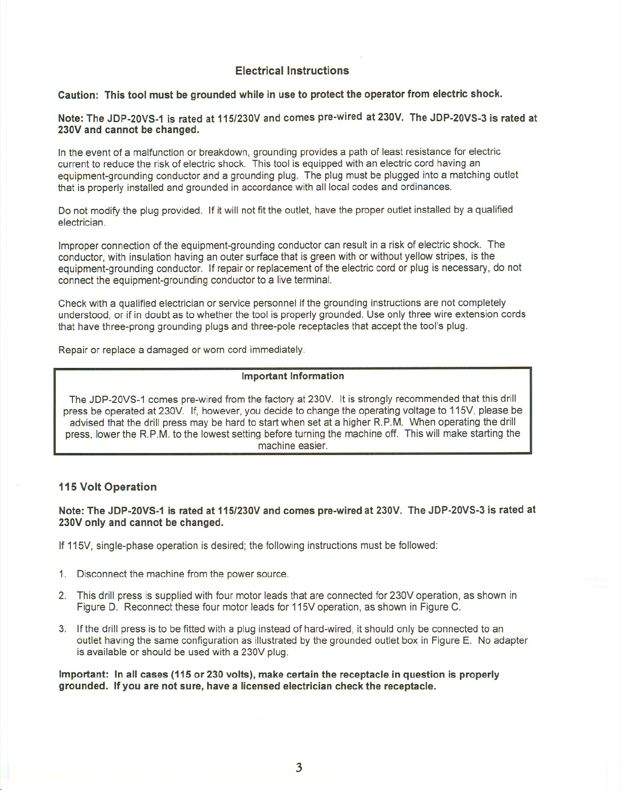
Electrical Instructions
Caution: This tool must be grounded while in use to protect the operator from electric shock.
Note: The JDP-20VS-1 is rated at 115/230V and comes pre-wired at 230V. The JDP-20VS-3 is rated at
230Vand cannot be changed.
In the event of a malfunction or breakdown, grounding providesa pathof leastresistance for electric
current to reduce the risk of electricshock. This tool isequippedwith an electric cord havingan
equipment-grounding conductor and a grounding plug. The plug must be plugged into a matchingoutlet
that is properly installed and grounded in accordancewith all localcodes and ordinances.
Do not modifythe plug provided. If itwill notfit the outlet, havethe properoutlet installed by a qualified
electrician.
Improper connection of the equipment-groundingconductor can result in a risk of electric shock. The
conductor, with insulation having an outer surface that isgreen with orwithout yellow stripes, is the
equipment-grounding conductor. If repairor replacementof the electriccord or plug is necessary,do not
connect the equipment-grounding conductorto a live terminal.
Check with a qualified electrician or service personnel if the grounding instructions are not completely
understood, or if in doubt as to whetherthe tool is properlygrounded. Use only three wire extension cords
that have three-prong grounding plugs and three-pole receptaclesthat acceptthe tool's plug.
Repair or replace a damaged or worn cord immediately.
Important Information
The JDP-20VS-1
press be operated at 230V. If, however,you decide to changethe operatingvoltage to 115V, please be
advised that the drill press may be hardto start when setat a higher R.P.M. When operating the drill
press, lower the R.P.M. to the lowestsetting before turning the machineoff. This will make starting the
comes pre-wiredfrom the factory at 230V. It is strongly recommendedthat this drill
machineeasier.
115 Volt Operation
Note: The JDP-20VS-1 is rated at 115/230Vand comes pre-wired at 230V. The JDP-20VS-3 is rated at
230Vonly and cannot be changed.
If 115V,single-phase operation isdesired; the following instructionsmust befollowed:
1. Disconnect the machinefrom the powersource.
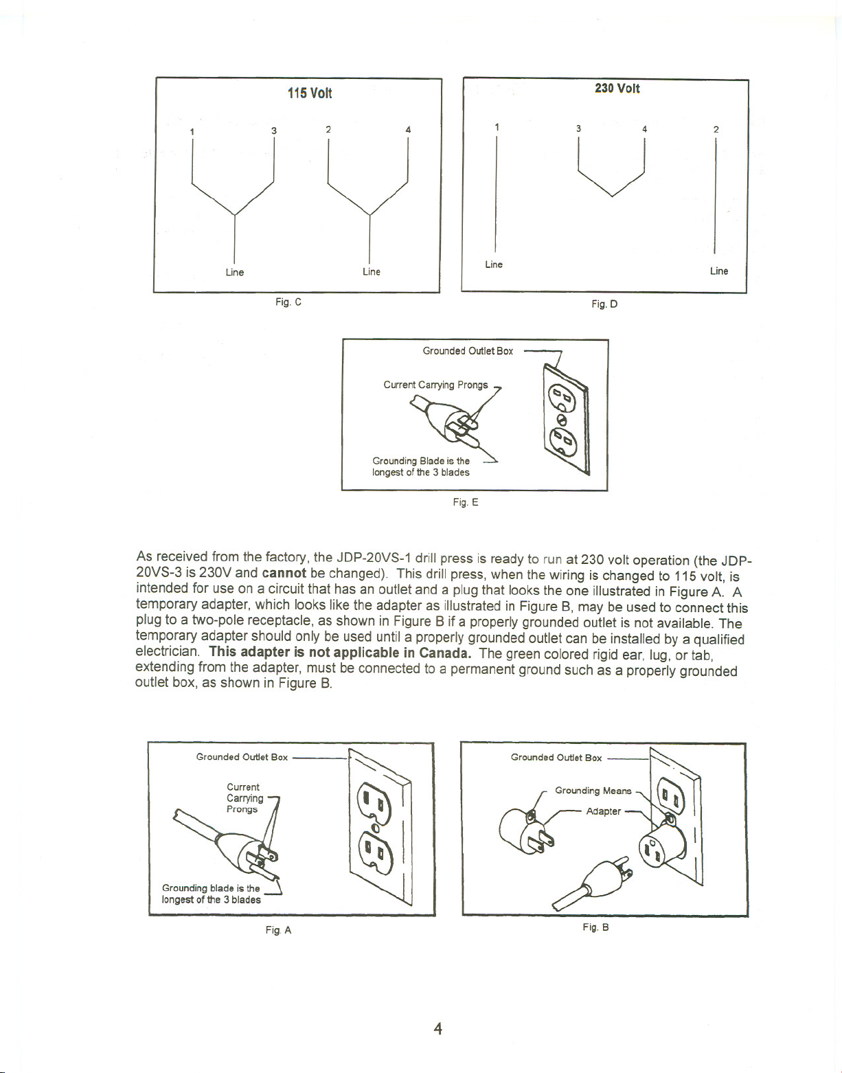
2. This drill press is supplied with four motor leads that are connected for 230V operation,as shown in
Figure D. Reconnect these four motor leadsfor 115Voperation, as shown in Figure C.
3. Ifthe drill press is to befitted with a plug insteadof hard-wired,it should only be connected to an
outlet having the same configuration as illustratedby the groundedoutlet box in Figure E. No adapter
is available or should be usedwith a 230V plug.
Important: Inall cases (115 or 230 volts), make certain the receptacle in question is properly
grounded. Ifyou are not sure, havea licensed electriciancheck the receptacle.
3
Page 6
115Volt
230Volt
Line
3
Fig. C
2
4
3
24
v
Fig. E
Line
Line
Fig. D
Line
Grounded Outlet Box
C"".~
GroundingBla~
longest of the 3 blades
As received from the factory, the JDP-20VS-1 drill press is ready to run at 230 volt operation (the JDP-
20VS-3 is230V and cannot be changed). This drill press,when thewiring is changed to 115volt, is
intendedfor use on a circuit that hasan outlet and a plug that looksthe one illustrated in FigureA. A
temporary adapter, which looks like the adapter as illustrated in Figure 8, may be usedto connect this
plug to a two-pole receptacle,as shown in Figure8 if a properly grounded outlet is not available. The
temporary adapter shouldonly be used until a properlygrounded outletcan be installed by a qualified
electrician. This adapter is not applicable in Canada. The green colored rigidear, lug, or tab,
extending from the adapter, must beconnected to a permanentgroundsuch as a properly grounded
outlet box, as shown in Figure 8.
Grounded Outlet Box
Grounding Means
~ Ad,p'oc-\,",
Grounding blade is the
longest of the 3 blades
Fig. A
fl
Fig.B
4
Page 7
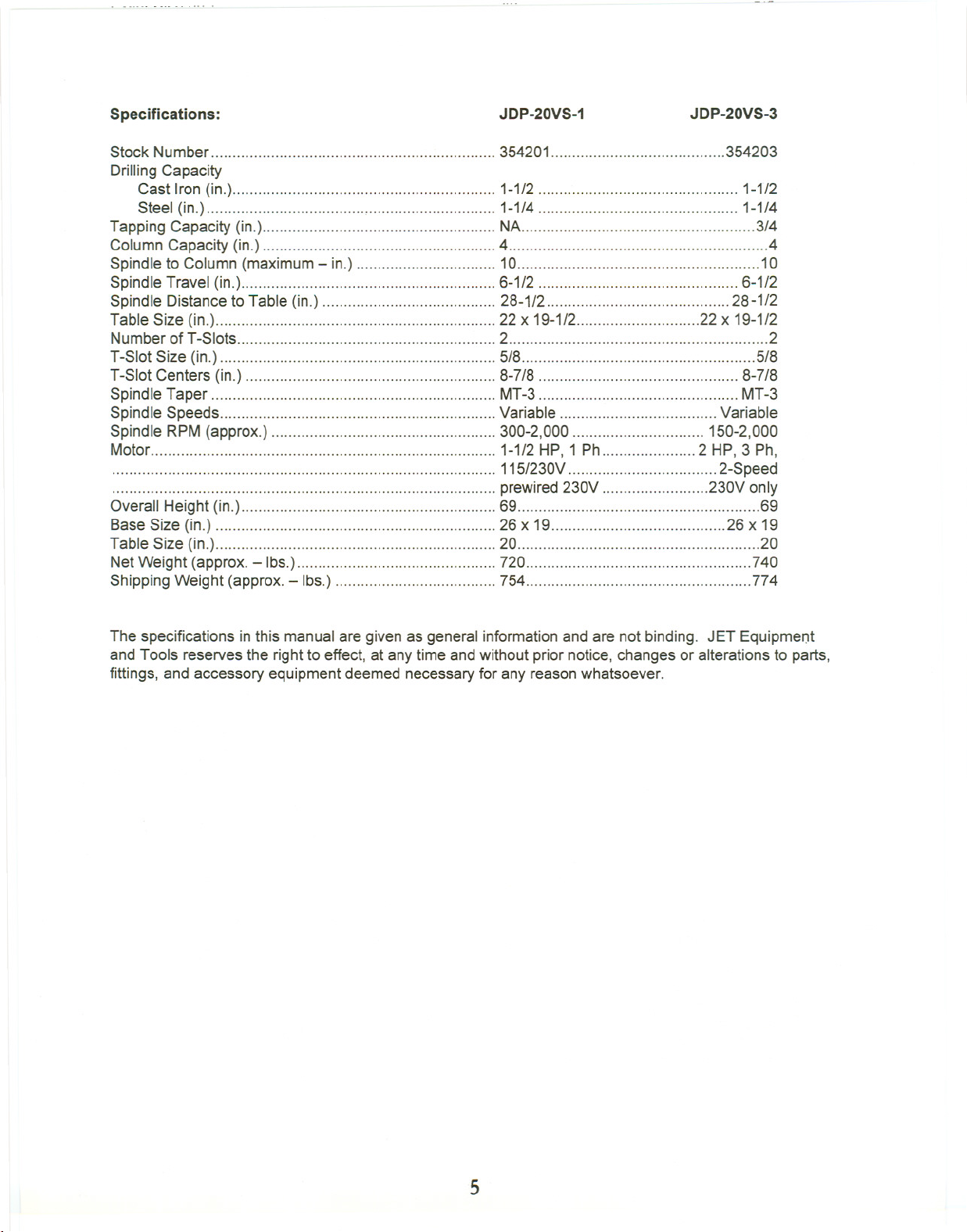
Specifications:
JDP-20VS-1
JDP-20VS-3
Stock Number... 354201 .354203
Drilling Capacity
Cast Iron (in.) 1-1/2 1-1/2
Steel (in.) , 1-1/4 1-1/4
Tapping Capacity (in.) NA 3/4
Column Capacity (in.) 4. 4
Spindle to Column (maximum- in.) 10 10
Spindle Travel (in.) 6-1/2 6-1/2
Spindle Distance to Table (in.) " 28-1/2 28-1/2
Table Size (in.) 22 x 19-1/2 22 x 19-1/2
Number of T-Slots 2 2
T-Slot Size (in.) 5/8 .5/8
T-Slot Centers (in.) 8-7/8 8-7/8
Spindle Taper MT-3 MT-3
Spindle Speeds Variable Variable
Spindle RPM (approx.) 300-2,000 150-2,000
Motor 1-1/2 HP, 1 Ph 2 HP, 3 Ph,
115/230V 2-Speed
prewired230V .230V only
Overall Height (in.) 69 .69
Base Size (in.) 26 x 19 26 x 19
Table Size (in.) 20 .20
Net Weight (approx. - Ibs.) 720 740
Shipping Weight (approx.-Ibs.) 754 774
The specifications in this manual are given as general information and are not binding. JET Equipment
and Tools reservesthe right to effect, atany time and without prior notice, changes or alterationsto parts,
fittings, and accessory equipment deemed necessaryfor any reasonwhatsoever.
5
Page 8
Unpacking and Clean-Up
1. Finish removing the shipping crate.
2. Remove the skid from under the press.
3. Remove the protective coating from all rust
protected surfaces with a soft cloth moistened
with kerosene or a mild solvent. Do notuse
acetone, gasoline, or paintthinner. Thesewill
damage painted surfaces.
4. To prevent rust, apply a thin coat of pastewax to
the table.
Installation
The drill press must be located in a dry, well lighted
area with adequate room on all sides ofthe
machine. The floor must be level andthe drill press
must rest solidly on the floor. The most accurate
and vibration free operation will require the drill
press to be bolted to the floor. While this is not
absolutely necessary, it is highly recommended.
Place shims near the three bolt holes to level the
drill press, if necessary. Equal pressure should be
applied to all three nuts when tightening to prevent
distorting the base.
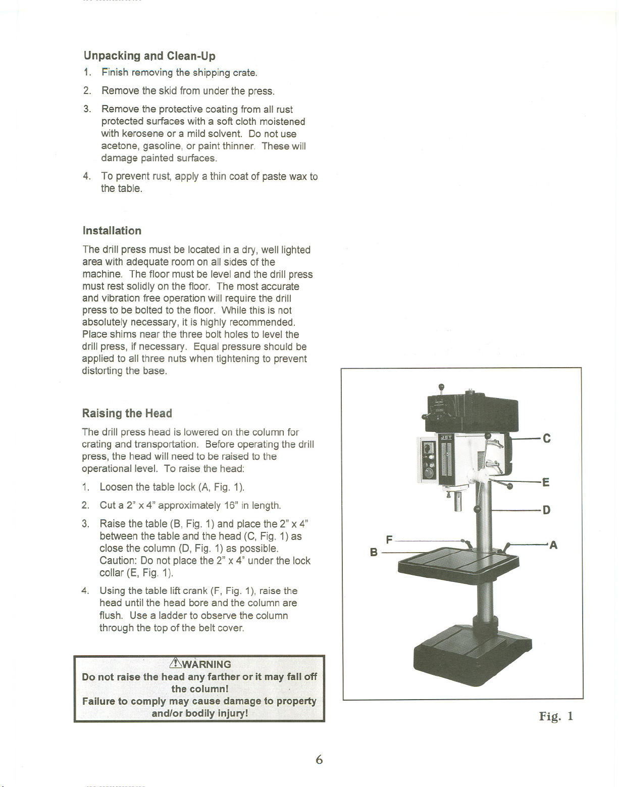
Raising the Head
The drill press head is loweredon thecolumn for
crating and transportation. Before operatingthe drill
press, the head will need to be raisedto the
operational level. To raise the head:
1. Loosen the table lock (A, Fig. 1).
2. Cut a 2" x 4" approximately 16" in length.
3. Raise the table (B, Fig. 1) and placethe 2" x 4"
between the table and the head (C, Fig. 1) as
close the column (D, Fig. 1)as possible.
Caution: Do not placethe 2"x 4" under the lock
collar (E, Fig. 1).
4. Using the table liftcrank (F, Fig. 1), raise the
head untilthe head bore and the column are
flush. Use a ladder to observethe column
through the top of the belt cover.
Failure to co
c
E
D
F
B
A
Fig. 1
6
Page 9
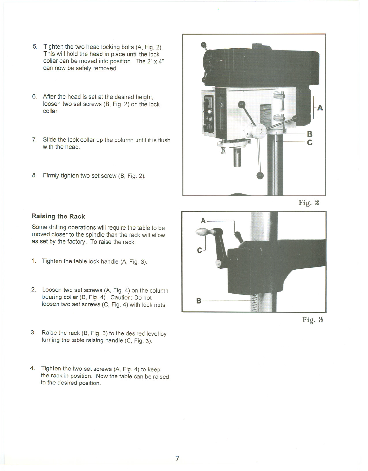
5. Tighten the two head locking bolts (A, Fig.2).
This will hold the head in place untilthe lock
collar can be moved into position. The 2" x 4"
can now be safely removed.
6. After the head is set at the desired height,
loosen two set screws (8, Fig.2) onthe lock
collar.
7. Slidethe lock collar up the column until it is flush
with the head.
8. Firmly tighten two set screw (8, Fig.2).
B
C
Fig. 2
Raising the Rack
Some drilling operationswill require the table to be
moved closer to the spindle than the rackwill allow
as set by the factory. To raise the rack:
1. Tighten the table lock handle (A, Fig.3).
2. Loosen two set screws (A, Fig. 4) on the column
bearing collar (8, Fig.4). Caution: Do not
loosen two set screws (C, Fig. 4) with lock nuts.
3. Raisethe rack (8, Fig. 3) to the desired level by
turning the table raising handle (C, Fig.3).
4. Tighten the two set screws (A, Fig. 4) to keep
the rack in position. Now the table can be raised
to the desired position.
A
c
B
Fig. 3
7
Page 10

ControlPanel- JDP-20VS-3
High-Low Switch (A, Fig. 5) - the center positionis
neutral. Turn to the right to selectthe lowmotor
speed. Turn to the left to selectthe highmotor
speed.
Drill Tap Switch (8, Fig. 5) - the center positionis
the off position. Push the switchto the left for the
drill function. Push the switchthe right for thetap
function.
Power Indicating Lamp (C, Fig.5) - indicates
power to the main panelwhen lit. This lampwill only
light up inthe drill or tap mode.
A
B
C
D
E
F
Fig. 5
Motor Start Button (D, Fig. 5) - activatesthe motor
in the drill or tap mode.
Tap Return Button (E, Fig. 5) - reverses the
spindle rotation and the tapwithdraws. Works only
in the tap mode.
Emergency Stop Button (F, Fig.5) - disconnects
the powerto the motor. Resetthe buttonby turning
90°.
Control Panel - JDP-20VS-1
On-Off Switch - turns power to the machineon and
off.
Changing Spindle Speeds
To change spindle speeds,turn the handwheel (A,
Fig.6) until the pointer shows the desiredspeed.
Speeds are approximate.
A
Fig. 6
Adjusting the Depth Stop for Drilling
Adjust the zero reading on the scale by:
1. Lower the quill to the bottomof itsstroke by
turning the handle (A, Fig.7) counter-clockwise
until it stops and hold in that position.
2. Turn the knurled knob(8, Fig. 7) untilthe pointer
reads zero. .
3. To set the depth stop, turn the knurled knob (8,
Fig. 7) to the desired setting. The quill will now
only advance to this setting.
BJf~
A
Fig. 7
8
Page 11

Adjusting the Depth Stop for Tapping
(JDP-20VS-3 only)
To adjust the depth stopfor tapping,follow the
instructions for adjusting the depthstop for drilling.
The major differences in the tap mode are two
micro-switches. One micro-switchautomatically
reverses (counter-clockwise) the spindle direction at
a predetermineddepth. The other micro-switch
forwards (clockwise) the direction of the spindle
once it is fully retracted.
Spindle Preparation
Thoroughly clean the inside of thespindle with a soft
dry cloth. Also clean any taper or arborto be used
in the spindle. If these are not kept clean, the taper
or arborwill not "seat" properly in the spindle and
may drop out unexpectedly.
Installing Drill Chuck Arbors or Taper Drill
Bits
1: Disconnect the machinefrom the powersource.
2. Make sure the spindle bore and thearbor or drill
bit is clean.
3. Place a protective piece of scrap wood onthe
table.
4. Raise the tableto approximately8" to 10" below
the spindle.
5. Insert the Morse Taper 3taper bit or chuck arbor
into the spindle. If the taper bit or chuck arbor
has a tang, turn the bit or arbor until the tang
engages the slot inside the spindle.
6. Lower the spindle with the handle assembly and
seat the taper bit or chuck arbor with pressure
on the handle assembly.
Removing Taper Drills or Chuck Arbors
1. Disconnect the machinefrom the powersource.
2. Place a protective piece of scrap wood onthe
table.
3. Raisethe table to approximately 8"to 10"below
the spindle.
4. Lower the spindle to expose the slots in the
spindle wall.
5. Insert the drift key intoone ofthe spindleslots
and tap gently until the drill bit or chuck arbor
loosens and falls out
9
Page 12
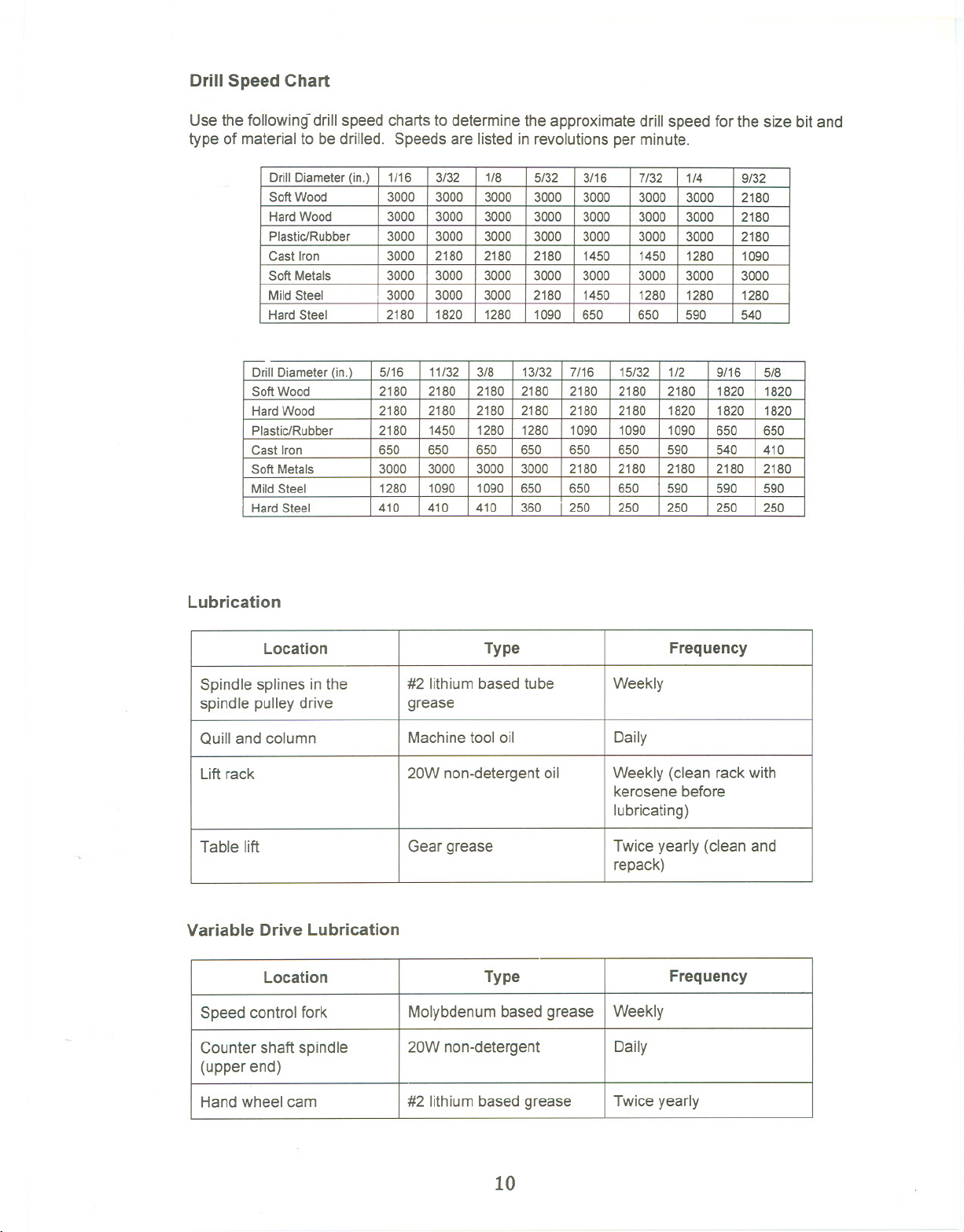
Drill Speed Chart
Use the following-drill speed charts to determinethe approximate drill speed for the size bit and
type of material to bedrilled. Speeds are listedin revolutions per minute.
-
Drill Diameter (in.)
Soft Wood
Hard Wood 2180 2180 2180 2180 2180 2180 1820 1820 1820
Plastic/Rubber 2180 1450 1280 1280 1090 1090 1090 650 650
Cast Iron 650 650 650 650 650 650 590 540 410
Soft Metals
Mild Steel 1280 1090
Hard Steel
Lubrication
Drill Diameter (in.)
Soft Wood 3000 3000 3000 3000 3000 3000
HardWood 3000 3000 3000
Plastic/Rubber 3000 3000 3000 3000 3000 3000 3000 2180
Cast Iron 3000 2180 2180
Soft Metals 3000 3000 3000 3000 3000
Mild Steel 3000 3000 3000 2180
Hard Steel 2180 1820 1280 1090 650 650
1/16
5/16 11/32 3/8 13/32 7/16 15/32 1/2 9/16 5/8
2180 2180 2180 2180 2180 2180 2180
3000 3000 3000 3000 2180 2180 2180 2180
410 410 410 360 250 250 250 250
3/32 1/8 5/32
3000
2180 1450 1450
1090 650 650 650
3/16
3000 3000 3000 2180
1450 1280
7/32 1/4
3000 2180
1280 1090
3000
3000 3000
1280 1280
590 540
590 590 590
9/32
1820 1820
2180
250
Location
Spindle splines inthe
spindle pulley drive
Quill and column
Lift rack
Table lift
#2 lithiumbasedtube
grease
Machinetool oil
20W non-detergentoil Weekly (clean rack with
Gear grease
Type Frequency
Variable Drive Lubrication
Location
Speed control fork
Molybdenumbased grease Weekly
Type
Counter shaft spindle 20W non-detergent
(upper end)
Handwheel cam
#2 lithiumbased grease
Weekly
Daily
kerosene before
lubricating)
Twice yearly (clean and
repack)
Frequency
Daily
Twice yearly
10
Page 13
t(76 6
JDP-20VS-1/3 HeadAssembly
30
3
50
51
1"
I ",
I
I
I
I 24
I
i 25
I 31
I
I
! 26
I
~
~
28 ~
27
21
20
19
19
19
20
11
Page 14

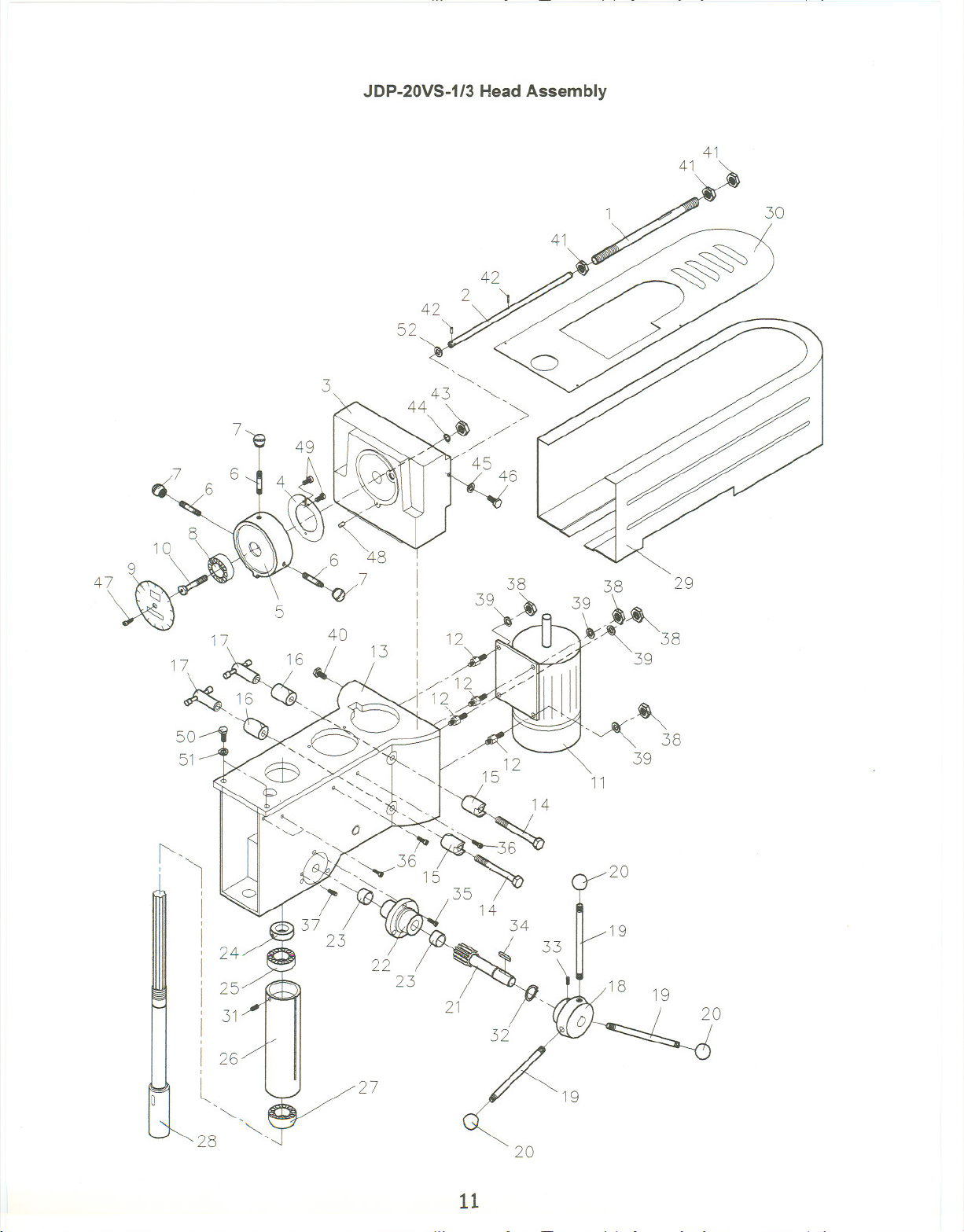
JDP-20VS-1/3 Head Assembly
Index Part
No. No.
1 70-1507 , Push Rod Tube 1
2 70-1509 Push Rod 1
3 70-1508 Spindle Cover 1
4 70-1516 CarnSpring 1
5 70-1512 Hub 1
6 70-1515 Handle 3
7 70-1515-1 Ball 3
8 A-632 Ball Bearing 1
9 71-1610 SpeedDial 1
10 70-1513 Bolt 1
11 70-1901 Motor (JDP-20VS-1 only) 1-1/2 HP, 1Ph 1
70-1903 Motor (JDP-20VS-3only) 2HP, 3Ph 1
12 71-1009 Motor Mount Bolt 4
13 71-1001B Head 1
14 70-1026B LockScrew 2
15 70-1019B HeadLock 2
16 70-1020B HeadLock 2
17 70-1022 Lock Handle 2
18 70-1407B Hub 1
19 70-1408 Handle 3
20 70-1408-1 Ball 3
21 70-1401B Piriion 1
22 71-1402B PinionSupport 1
23 71-1402-1 Bushing 2
24 71-1004B Nut 1
25 BB-62062 Ball Bearing 1
26 71-1003B... QuilL.. 1
27 BB-5206 Ball Bearing 1
28 71-1002B Spindle 1
29 70-1014 Belt Cover 1
30 70-1014-1 Top Plate 1
31 TS-0267031 Set Screw 1/4x 5/16 1
32 JDP20VS-32 Snap Ring R25 1
33 TS-0270021 Set Screw 5/16 x 5/16 1
34 JDP20VS-34 Key 6 x 6 x 30 1
35 JDP20VS-35 Pan Head Screw 1/4x 3/4 3
36 JDP2:0VS-36 Pan HeadScrew 1/4 x 1/2 4
37 TS-0270101 Set Screw 5/16x 1-1/4 2
38 TS-0561031 Hex Nut 3/8 4
39 TS-0680041 Washer 3/8 4
40 TS-0051011 HexCapBolt 5/16x 1/2 2
41 TS-0561072 Hex Nut 5/8-18UNF 3
42 JDP20VS-42 Pin 3 x 18 2
43 TS-0561052 Hex Nut 1/2-20UNF 1
44 TS-0720111 SpringWasher 1/2 1
45 TS-0680041 Washer 3/8 1
46 TS-0051051 HexCap BoiL 5/16 x 1 2
47 JDP20VS-47 HexSocket Cap Screw 1/4x 1/4 1
48 JDP20VS-48 Pin 5 x 20 1
Description
Size
Qty.
12
Page 15

JDP-20VS-1/3 Head Assembly (continued)
49 .. .JDP20VS-49 Screw... ... 3/16 x 3/8 ...3
50 TS-0061041 HexCap BoiL 7/16 x 1-1/4 3
51 TS-0680051 SpringWasher 7/16 , 2
52 JDP20VS-52 Washer , , , , , ., 1
13
Page 16
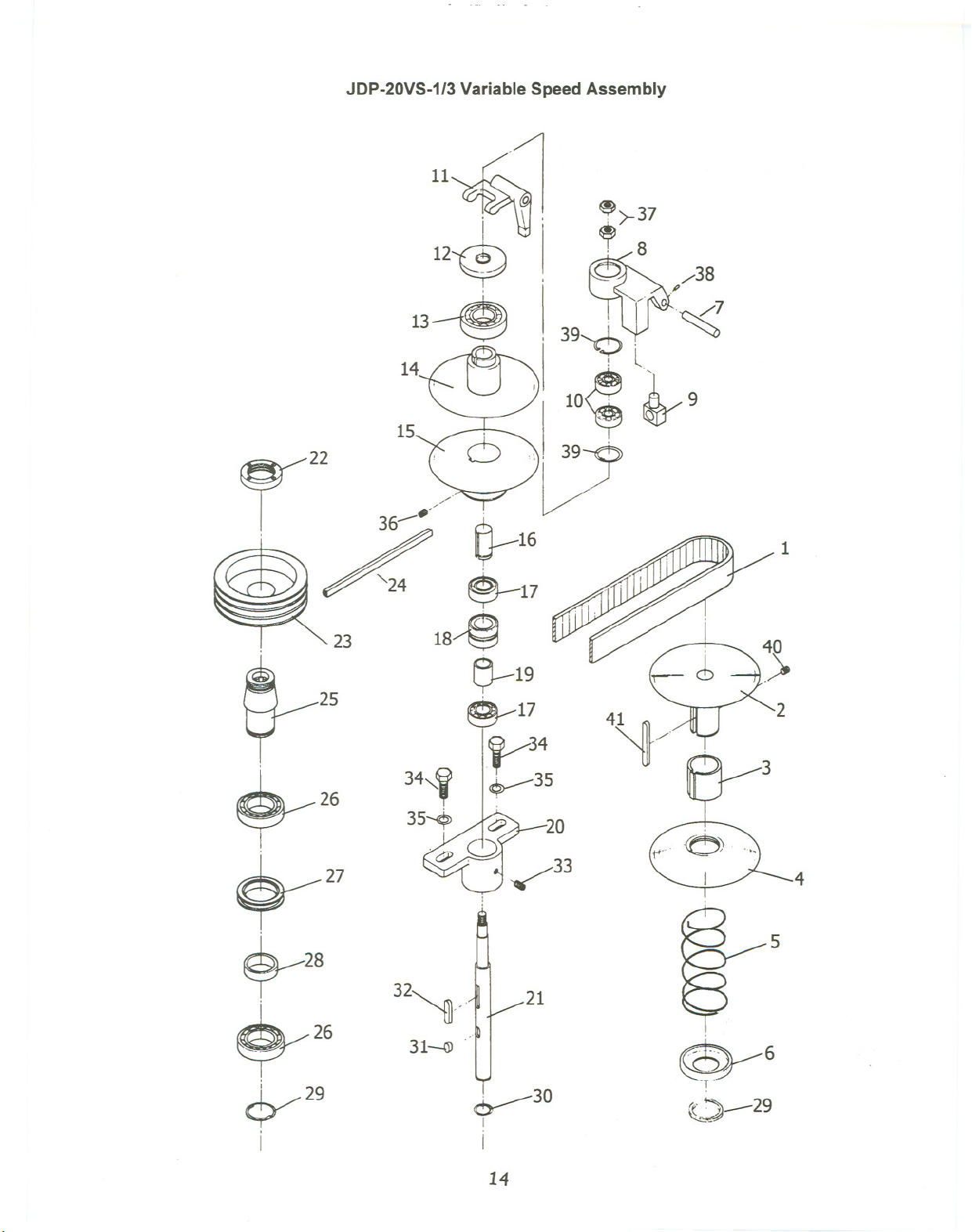
JDP-20VS-1/3 Variable Speed Assembly
11~ ~>-37
~~ ,8
12$ ~./38
13--@J . 39~~~
14.'/ ~~ ~I
15~1 .
22 -~~y
r 36~. ~16
;/ ~ - -<'"
~24 ~17 . ~i
0 ~
23
25
18/~
~19
. 17
~34
~35
! l
,
10, 9
~. .
~
~
1
$-26
~27
$--28
~26
~29
I
32~..
31~
~30
I
I
20
4
21
~--6
~F
",.'~
1S:.4-- 29
14
Page 17
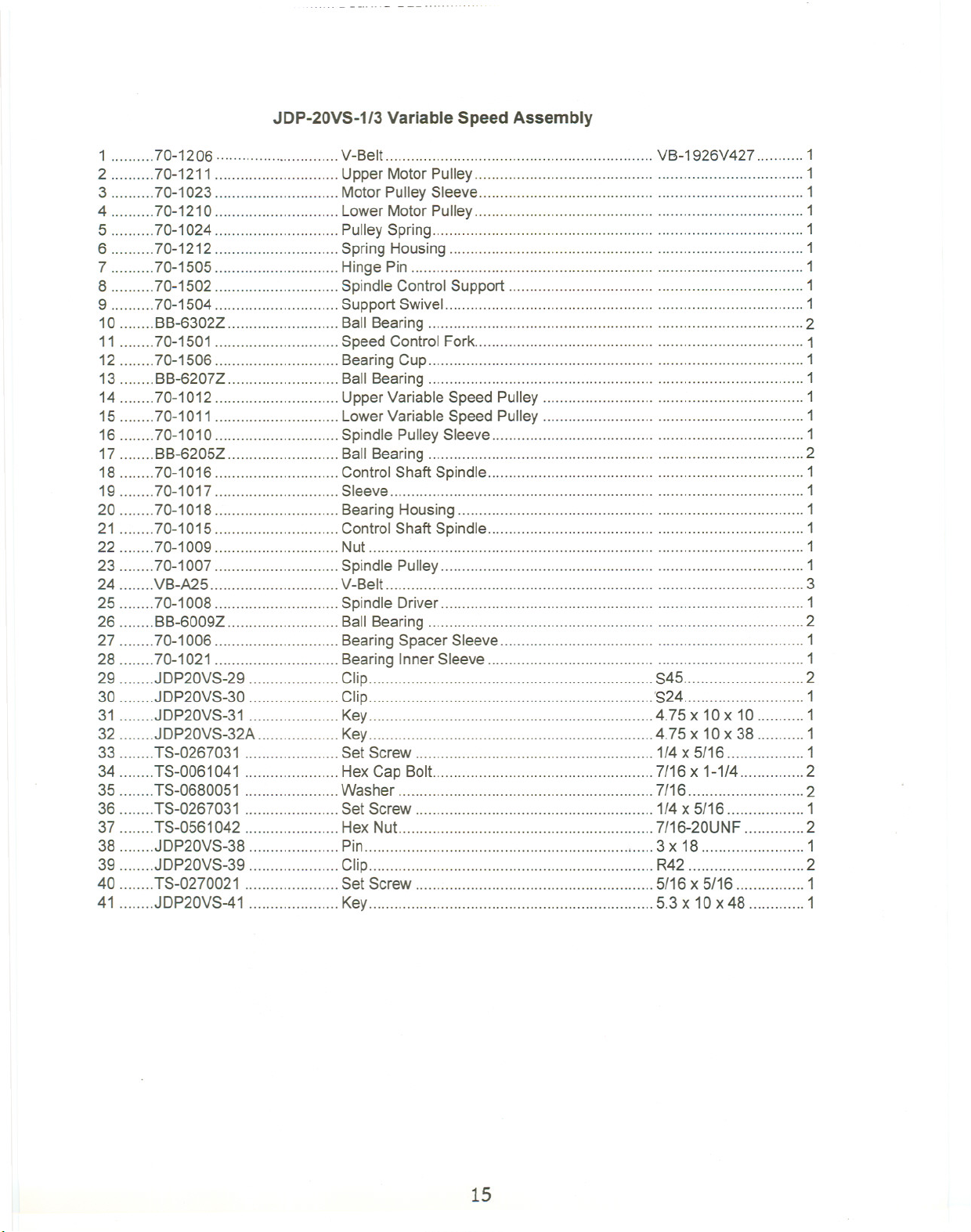
JDP-20VS-1/3 Variable Speed Assembly
1 70-1206 V-Belt VB-1926V427 " 1
2 70-1211 UpperMotorPulley 1
3 70-1023 MotorPulleySleeve 1
4 70-1210 LowerMotorPulley 1
5 70-1024 PulleySpring 1
6 70-1212 SpringHousing 1
7 70-1505 HingePin 1
8 70-1502 SpindleControlSupport 1
9 70-1504 Support Swivel 1
10 BB-6302Z Ball Bearing ... '''' '''''''''''''''''' 2
11 70-1501 Speed ControlFork 1
12 70-1506 BearingCup .. 1
13 BB-6207Z BallBearing 1
14 70-1012 UpperVariableSpeed Pulley 1
15 70-1011 LowerVariable Speed Pulley 1
16 70-1010 Spindle PulleySleeve 1
17 BB-6205Z BallBearing 2
18 70-1016 ControlShaft Spindle 1
19 70-1017 Sleeve 1
20 70-1018 BearingHousing 1
21 70-1015 ControlShaft Spindle 1
22 70-1009 Nut 1
23 70-1007 Spindle Pulley 1
24 VB-A25 V-Belt 3
25 70-1008 Spindle Driver 1
26 BB-6009Z BallBearing 2
27 70-1006 BearingSpacer Sleeve 1
28 70-1021 BearingInnerSleeve 1
29 JDP20VS-29 ." Clip S45 2
30 JDP20VS-30 Clip 'S24 1
31 JDP20VS-31 Key 4.75 x 10 x 10 1
32 JDP20VS-32A Key 4.75 x 10 x 38 1
33 TS-0267031 Set Screw 1/4x 5/16 1
34 TS-0061041 HexCap BoiL 7/16 x 1-1/4 2
35 TS-0680051 Washer 7/16 2
36 TS-0267031 Set Screw 1/4x 5/16 1
37 TS-0561042 Hex Nut.. 7/16-20UNF 2
38 JDP20VS-38 Pin 3 x 18 1
39 JDP20VS-39 Clip R42 2
40 TS-0270021 Set Screw 5/16 x 5/16 1
41 JDP20VS-41 Key 5.3 x 10 x 48 1
15
Page 18
16
16
Page 19

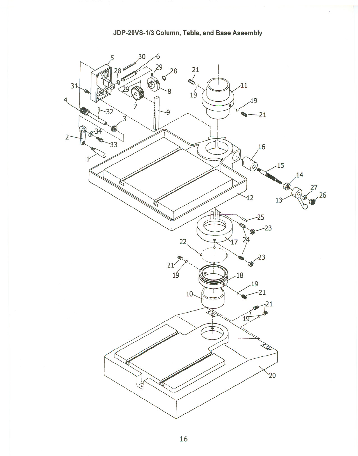
JDP-20VS-1/3 Column, Table, and Base Assembly
1 70-3008 Handle 1
2 70-1306 LiftCrank 1
3 BB-51102 ... Thrust Bearing 1
4 70-1302 Worm Shaft ... 1
5 71-1301 Gear Box 1
6 70-1305 Worm Gear Shaft 1
7 71-1302 ...Gear ... 1
8 70-1303 Worm Gear 1
9 71-3003 Gear Rack.. ... ... .. 1
10 71-3005 Column 1
11 70-1008 Collar 1
12., 71-2001 Table 1
13 71-2005 Lock Handle "'"'''''' 1
14 71-2004 Table Lock NuL 1
15 71-2003 Table LockScrew 1
16 71-2002 Table Lock 1
17 70-2005 Bearing Ring 1
18 70-2004 Collar 1
19 70-2006 Bushing 6
20 .. :.71-3001 .. Base ... ... ... ... ............ . 1
21 TS-0272021 Set Screw 7/16 x 7/16 6
22 SB-3/8 Steel Bal! 39
23 TS-0561021 Hex Nut 5/16 2
24 TS-0270091 '''''''''''''''''''''' Set Screw 5/16 x 1 2
25 JDP20YS-25 Pin 4 x 40 1
26 TS-0561031 """"""""""" Hex Nut 3/8"""""""""""""'" 1
27 TS-0680041 Washer. ... ... 3/8 1
28 JDP20YS-28 Clip R15 2
29 TS-0267021 Set Screw 1/4x 1/4 2
30 JDP20YS-30A Key 5 x 5 x40 1
31 TS-0208081 Hex Socket Cap Screw 5/16 x 1-1/2 4
32 JDP20YS-32B Pin 6 x 30 1
33 TS-0208021 Hex Socket Cap Screw 5/16 x 1/2 1
34 TS-0680031 .. Washer 5/16 1
17
Page 20

JDP-20VS-1/3 Depth Stop and Control Box Assembly
18
Page 21

JDP-20VS Depth Stop and Control Box Assembly
1 71-1601 On-OffSwitch(JDP-120VS-1only) 1
2 70-17630 LimitBlock 2
3 71-1704 LimitSupport .., 2
4 71-1703 LimitGuide 1
5 70-1611B Scale , 1
6 70-1612B StrokeStopBracket " 1
7 71-1706 Tapping ControlNut 1
8 50-1610 Depth Indicator 1
9 70-1606B Screw 1
10 50-1606 Micro-Dial 1
11 50-1615 Screw Support 1
12 70-1404B.. Spring 2
13 70-141OB Spring Protector 2
14 71-1609B Bracket 1
15 .50-1607 ., Knob 1
16 71-1701 Control Box(JDP-20VS-3only) 1
JDP-20VS-3CB ControlBoxComplete (JDP-20VS-3only) 1
17 E-001 Power IndicatorLight(JDP-20VS-3only) 1
18 E-101 High-LowSwitch(JDP-20VS-3only) 1
19 E-102 Start Button(JDP-20VS-3only) 1
20 E-103 ...Drill-TapSwitch 1
21 E-104 Return Switch. ... ... 1
22 .. E-106 Emergency StopSwitch 1
23 JDP20VS-23
24 TS-0561072 Hex Nut 5/8-18UNF 1
25 ... TS-0270101 .. Set Screw 5/16 x 1-1/4 2
Pin 3 x20 1
26 TS-0208071 HexSocketCapScrew 5/16x 1-1/4 1
27 JDP20VS-27 Screw 3/16x 1/2 4
28 JDP20VS-28A Pin 3x 12 1
29 TS-0270111 SetScrew 5/16
x 1-1/2 2
30 TS-0561021 HexNuL 5/16 2
31 TS-0267021 .. Set Screw ... ... ... ... ... ... 1/4"x1/4" 1
32. ... ... .JDP-20VS-32.. ... ... ... ... ... Round Head Screw... ... ... ... ... ... M3xO.5 1
33 TS-0680011 Washer 1/4" 1
34 .JDP-20VS-34 Limite Plate 1
19
Page 22
Electrical Panel Components (JDP-
20VS-3)
10
[£]
9
CL-4L
[ill
8
C-11 L
8
Fu
2A
7
I
0
I r
1
0 V.
24V.
1
1
I
Transformer
r
r 1
220V
380V.
440V .
.0
. 1
6
1- I
I
I
I
9
15. 11
S S T -L R1 S1 T1 -L 0, 1, 7, 8, 9 , 10, 12, 13, 15, 16,
Low
W2
S1
U2
Switch
V2
Hi
U1
W1
9
6
R1
V1
T1
1
/'
~
2
3
Tap Drill
9l8Ti2
@] Light G:1' 12
7l6T7
~4
~
5
20
Page 23

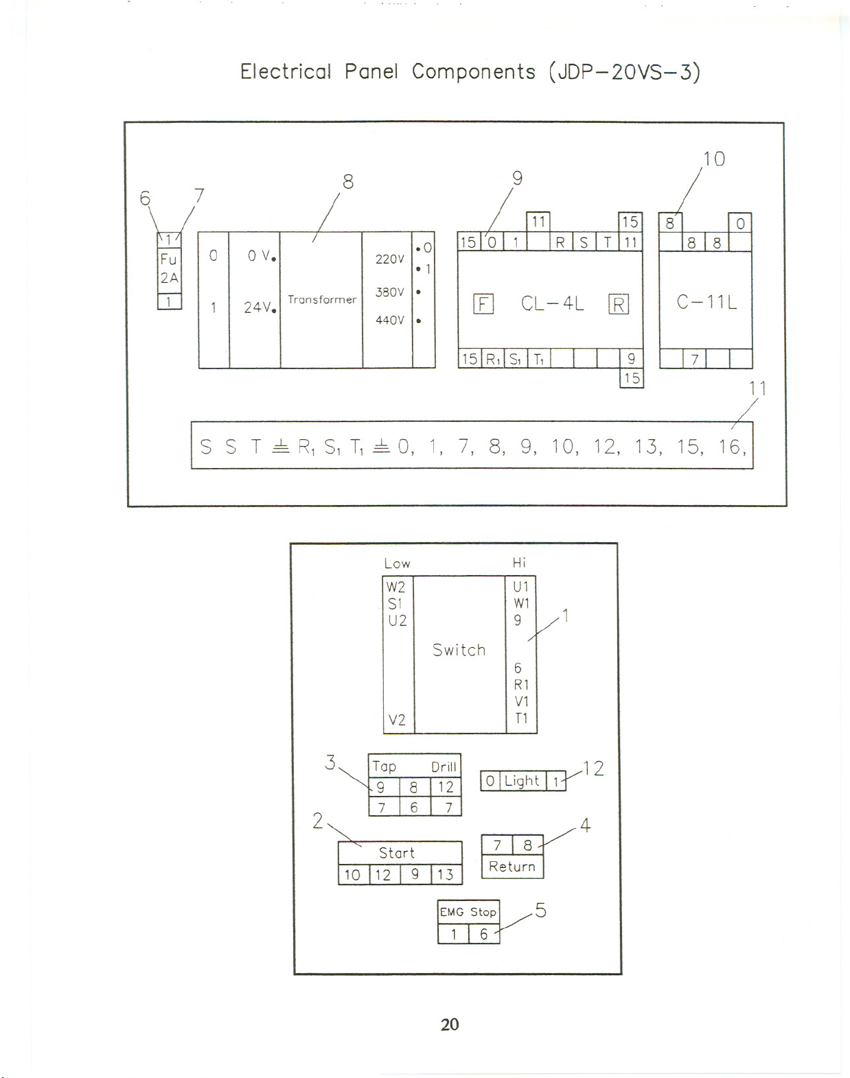
Electrical Panel Components (JDP-20VS-3 only)
1 E-101 High-LowSwitch 1
2 E-102 Start Button 1
3 E-103 ""'"'''''''''''''''' Drill-TapSwitch ; 1
4 E-104
; ReturnSwitch : 1
5 E-106 EmergencyStop Switch 1
6 E-013 :': Fuse(2AMP) 1
7 E-014 FuseSeat ..; ,....,.1
8 E-111 Transformer 1
9 E-016 MagneticStarter (CL-4L) '.1
10 E-015 MagneticStarter (C-11L) 1
11 E-110 Terminal Relay 1
12 """" E-001 Light(24v) . '. 1
2~
Page 24

R
s
T
TC220V
MR
I\J
I\J
T1 51 R1
W2 V2 U2 W 1 V1 U1
MF
2A
AC24V
a
I 0
~
EMG Stop C
r---
I Drill
I 0-
S I Off
.
TAP
4P18P Start
CS I
I
6 , .. 0 .
12
J 6
LS1 Return
0--2.2...0 I ,
I
I
~
(
J
3 D
-L 8
R
S
9
SR
I : Lo-
I I
c::b :
I 0
--L t:::J
MR
E
I
13 LS2
Page 25

Page 26

/
Page 27

Page 28

 Loading...