

Page 1
This .pdf document is bookmarked
Operating Instructions and Parts Manual
10” x 16” Horizontal Band Saw
Models J-7020, J-7040
WALTER MEIER (Manuf acturing) Inc.
427 New Sanford Road
LaVergne, Tennessee 37086 Part No. M- 414472
Ph.: 800-274-6848 Revision B 03/2012
www.walt er meier.c om Copyright © 2012 Walt er Meier (M anufacturi ng) Inc.
Page 2
1.0 Warranty and Service
Walter Meier (Manufacturing) Inc., warrants every product it sells. If one of our tools needs service or repair, one of
our Authorized Service Centers located throughout the United States can give you quick service. In most cases, any
of these Walter Meier Authorized Service Centers can authorize warranty repair, assist you in obtaining parts, or
perform routine maintenance and major repair on your JET® tools. For the name of an Authorized Service Center in
your area call 1-800-274-6848.
MORE INFORMATION
Walter Meier is consistently adding new products to the line. For complete, up-to-date product information, check with
your local Walter Meier distributor, or visit waltermeier.com.
WARRANTY
JET products carry a limited warranty which varies in duratio n based upon the product (MW = Metalworking, WW =
Woodworking).
WHAT IS COVERED?
This warranty covers any defects in workmanship or materials subject to the e xceptions stated below. Cutting tools,
abrasives and other consumables are excluded from warranty coverage.
WHO IS COVERED?
This warranty covers only the initial purchaser of the product.
WHAT IS THE PERIOD OF COVERAGE?
The general JET warranty lasts for the time period specified in the product literature of each product.
WHAT IS NOT COVERED?
Five Year Warranties do not cover woodworking (WW) products used for commercial, industrial or educational
purposes. Woodworking products with Five Year Warranties that are used for commercial, industrial or education
purposes revert to a One Year Warranty. This warranty does not cover defects due directly or indirectly to misuse,
abuse, negligence or accidents, normal wear-and-tear, improper repair or alterations, or lack of maintenance.
HOW TO GET SERVICE
The product or part must be returned for examination, postage prepaid, to a location designated by us. For the name
of the location nearest you, please call 1-800-274-6848.
You must provide proof of initial purchase date and an explanation of the complaint must accompany the
merchandise. If our inspection discloses a defect, we will repair or replace the product, or refund the purchase price,
at our option. We will return the repaired product or replacement at our expense unless it is determined by us that
there is no defect, or that the defect resulted from causes not within the scope of our warranty in which case we will,
at your direction, dispose of or return the product. In the event you choose to have the product returned, you will be
responsible for the shipping and handling costs of the return.
HOW STATE LAW APPLIES
This warranty gives you specific legal rights; you may also have other rights which vary from state to state.
LIMITATIONS ON THIS WARRANTY
WALTER MEIER (MANUFACTURING) INC., LIMITS ALL IMPLIED WARRANTIES TO THE PERIOD OF THE
LIMITED WARRANTY FOR EACH PRODUCT. EXCEPT AS STATED HEREIN, ANY IMPLIED WARRANTIES OR
MERCHANTABILITY AND FITNESS ARE EXCLUDED. SOME ST ATES DO NOT ALLOW LIMITATIONS ON HOW
LONG THE IMPLIED WARRANTY LASTS, SO THE ABOVE LIMITATION MAY NOT APPLY TO YOU.
WALTER MEIER SHALL IN NO EVENT BE LIABLE FOR DEATH, INJURIES TO PERSONS OR PROPERTY, OR
FOR INCIDENTAL, CONTINGENT, SPECIAL, OR CONSEQUENTIAL DAMAGES ARISING FROM THE USE OF
OUR PRODUCTS. SOME STATES DO NOT ALLOW THE EXCLUSION OR LIMITATION OF INCIDENTAL OR
CONSEQUENTIAL DAMAGES, SO THE ABOVE LIMITATION OR EXCLUSION MAY NOT APPLY TO YOU.
Walter Meier sells through distributors only. The specifications in Walter Meier catalogs are given as general
information and are not binding. Members of Walter Meier reserve the right to effect at any time, without prior notice,
those alterations to parts, fittings, and accessory equipment which they may deem necessary for any reason
whatsoever. JET® branded products are not sold in Canada by Walter Meier.
2
Page 3

2.0 Table of contents
Section Page
1.0 Warranty and Service ............................................................................................................................................ 2
2.0 Table of contents ................................................................................................................................................... 3
3.0 Safety Warnings..................................................................................................................................................... 4
4.0 About this machine and manual ............................................................................................ ............................... 6
5.0 Specifications ......................................................................................................................................................... 6
6.0 Ma chine setup........................................................................................................................................................ 8
6.1 Un crating and spotting ...................................................................................................................................... 8
7.0 Electrical connections............................................................................................................................................ 8
8.0 Operating instructions ........................................................................................................................................... 8
8.1 Controls .............................................................................................................................................................. 8
8.2 Setting blade speed ........................................................................................................................................... 8
8.3 Raising/lowering saw head ............................................................................................................................... 9
8.4 Controlling the cut: Hydraulic feed control ....................................................................................................... 9
8.5 Evaluating cutting efficiency ............................................................................................................................ 10
8.6 Blade selection................................................................................................................................................. 10
8.7 Blade break-in procedures .............................................................................................................................. 10
9.0 Work setup ........................................................................................................................................................... 10
9.1 Securing workpiece for square cuts ............................................................................................................... 10
9.2 Adjusting vise for angle cuts ........................................................................................................................... 10
9.3 Installation and adjustment of work stop........................................................................................................ 11
10.0 Starting the Saw ........................................................................................................ ........................................ 11
10.1 Coolant flow ................................................................................................................................................... 12
10.2 Coolant mixture and quantity ........................................................................................................................ 12
11.0 Adjustments ....................................................................................................................................................... 12
11.1 Blade tracking adjustment............................................................................................................................. 12
11.2 Factory or field procedure ............................................................................................................................. 12
11.3 Blade guide bearing adjustment ................................................................................................................... 13
11.4 Test cutting to verify adjustment accuracy .................................................................................................. 14
11.5 Limit switch adjustment ................................................................................................................................. 14
12.0 Maintenance....................................................................................................................................................... 14
12.1 Cleanin g ......................................................................................................................................................... 14
12.2 Lubrication ...................................................................................................................................................... 15
12.3 Changing blades ............................................................................................................................................ 15
12.4 Changing drive belt........................................................................................................................................ 15
12.5 Replacing drive motor ................................................................................................................................... 16
12.6 Adjusting counterbalance spring .................................................................................................................. 16
12.7 Replacing drive wheel ................................................................................................................................... 16
12.8 Replacing idler wheel or idler bearing .......................................................................................................... 16
12.9 Adjusting blade guides .................................................................................................................................. 16
12.10 Replacing carbide blade guide ................................................................................................................... 17
12.11 Replacing guide bearings ........................................................................................................................... 17
12.12 Replacing blade edge bearings .......................................................................................... ........................ 17
12.13 Replacing wire brush................................................................................................................................... 17
13.0 Tr oublesh ootin g the J-7020/7 040 Band Saws ................................................................................................ 18
14.0 Replacement Parts ............................................................................................................................................ 19
14.1. 1 Base (J-7020/7040) – E xploded Vi ew ...................................................................................................... 20
14.1.2 Base (J-7020/7040) – Parts List............................................................................................................... 21
14.2. 1 Head (J-7020/7040) – E xploded Vi ew ...................................................................................................... 24
14.2. 2 Head (J- 7020/7040) – Parts List .............................................................................................................. 25
15.0 Electrical Connections....................................................................................................................................... 28
15.1 El ectrical Connect ions – si ngle pha se only (model J-7020) ...................................................................... 28
15.2 El ectrical Connect ions – t hree phase only (model J-7040) ........................................................................ 29
3
Page 4

3.0 Safety Warnings
General Cautions
- Misuse of this machine can cause serious injury.
- For safety, the machine must be set up, used and
serviced properly.
- Read, understand and follow the instructions in the
operator’s and parts manual which was shipped
with your machine.
When setting up the machine:
- Always avoid using the machine in da mp or poorly
lighted work areas.
- Always be sure the machine is securely anchored
to the floor or the work bench.
- Always keep the machine guards in place.
- Always put the st art switch in the “OFF” position
before plugging in the machine.
When using the machine:
- Never operate the machine with safety guards
missing.
- Always wear safety glasses with side shields (See
ANSI Z87.1)
- Never wear loose clothing or jewelry.
- Never overreach; you may slip and fall into the
machine.
- Never leave the machine running while unattended.
- Always shut the machine off when not in use.
When servicing the machine:
- Always unplug the machine from the electrical
power before servicing.
- Always follow the instructions in the operators and
parts manual when changing accessory tools or
parts.
- Never modify the machine without consulting
Walter Meier (Manufacturing) Inc.
You — the stationary power tool user — hold the key
to safety.
Read and follow these simple rules for best results
and full benefits from your machine. Used properly,
JET machinery is among the best in design and
safety. However, any machine used improperly can
be rendered inefficient and unsafe. It is mandatory
that those who use our products be properly trained in
how to use them correctly. They should read and
understand the Operator’s and Parts Manual as well
as all labels affixed to the machine. Failure in
following all of these warnings can cause serious
injuries.
Gene ra l Mach inery Warn i ngs
1. Always wear protective eye wear when operating
machinery. Eye wear shall be impact resistant,
protective safety glasses with side shields which
comply with ANSI Z87.1 specifications. Use of
eye wear which does not comply with ANSI Z87.1
specifications could result in severe injury from
the breakage of the eye protection.
2. Wear proper apparel. No loose clothing or jewelry
which can get caught in moving parts. Rubber
soled, nonslip, footwear is recommended for best
footing.
3. Do not overreach. Failure to maintain a proper
working position can cause you to fall into the
machine or cause your clothing to get caught —
pulling you into the machine.
4. Keep guards in place and in proper working
order. Do not operate the machine with the
guards removed.
5. Avoid dangerous working environments. Do not
use stationary machine tools in wet or damp
locations. Keep work areas clean and well lit.
6. Special electrical precautions should be taken
when working on flammable materials.
7. Avoid accidental starts by being sure that the
start switch is in the “OFF” position before
plugging in the machine.
8. Never leave the machine running while
unattended. The machine shall be shut off
whenever it is not being used.
9. Disconnect the electrical power before servicing,
whenever changing accessories or when general
maintenance is done on the machine.
10. Maintain all machine tools with care. Follow all
maintenance instructions for lubricating and the
changing of accessories. No attempt shall be
made to modify or have makeshift repairs done to
the machine. This not only voids the warranty but
also renders the machine unsafe.
11. If there is any risk of tipping or sliding, the
machinery must be anchored to the floor.
12. Secure your work. Use clamps or a vise to hold
your work, when practical. It is safer than using
your hands and it frees both hands to operate the
machine.
13. Never brush chips away while the machine is in
operation.
14. Keep work area clean. Cluttered areas invite
accidents.
15. Remove adjusting keys and wrenches before
turning the machine on.
16. Use the right tool. Don’t force a tool or
attachment to do a job for which it was not
designed.
17. Use only recommended accessories and follow
manufacturer’s instructions pertaining to them.
Page 5

18. Keep hands in sight and clear of all moving parts
A
and cutting surfaces.
19. All visitors should be kept at a safe distance from
the work area. Make your workshop co mpletely
safe by using padlocks, master switches, or by
removing starter keys.
20. Know the tool you are using; its application,
limitations, and potential hazards.
General Electrical Cautions
This machine should be grounded in accordance with
the National Electrical Code and local codes and
ordinances. The work should be done by a qualified
electrician. The machine should be grounded to
protect the user from electrical shock.
Wi re Sizes
CAUTION: For circuits that are a great distance fro m
the electrical service box, the wire size must be
increased in order to deliver ample voltage to the
motor. To minimize power losses and to prevent
motor overheating and burnout, the use of wire sizes
for branch circuits or electrical extension cords
according to the following table is recommended:
Conductor
length
240 volt lines 120 volt lines
0-50 feet No. 14 No. 14
50-100 feet No. 14 No. 12
Over 100 feet No. 12 No. 8
WG (American Wire Gauge) number
Safet y Inst ruc tions on Sawing Systems
1. Always wear leather gloves when handling
saw blade. The operator shall not wear gloves
when operating the machi ne.
2. All doors shall be closed, all panels replaced,
and other safety guards in place prior to the
machine being started or opera ted.
3. Be sure that the blade is not in contact with the
workpiece when the motor is started. The
motor shall be started and you should allow
the saw to achieve full speed before bringing
the saw bl ade into contact with the workpiece.
4. Keep hands away from the blade area.
5. Remove any cut off piece carefully while
keeping y our hands free of the blade a rea.
6. Saw must be stopped and electrical supply
must be cut off before any blade replacement
or adjustment of blade support mechanism is
done, or before any attempt is made to change
the drive belt s or before a ny per iodic ser vice or
maintenance i s perfor m ed on the saw.
7. Remove all loose items and unnecessary
workpieces from the area before starting
machine.
8. Bring adjustable saw guides and guards as
close as pos sible t o the workpiece.
9. Always wear protective eye wear when
operating, servicing, or adjusting machinery.
Eyewear shall be impact resistant, protective
safety glasses with side shields complying with
ANSI Z87.1 specifications. Use of eye wear
which does not comply with ANSI Z87.1
specifications could result in severe injury
from br eakage of eye prot ection.
10. 10. Nonslip footwear and safety shoes are
recommended.
11. Wear ear protectors (plugs or muffs) during
extended per iods of operation.
12. The workpiece, or part being sawed, must be
securely clamped before the saw blade enters
the workpiece.
13. Remove cut off pieces carefully, keeping
hands away from saw blade.
14. Saw must be stopped and electrical supply
disconnected before reaching into cutting area.
15. Avoid contact with coolant, especially guarding
your eyes.
Familiarize yourself with the following safety notices used in this manual:
This means that if precautions are not heeded, it may result in minor injury and/or possible
machine da ma ge.
This means that if precautions are not heeded, it may result in serious injury or possibly even
death.
5
Page 6

4.0 About this machine and manual
The JET Models J-7020 and J-7040 Horizontal Cut-Off Band Saws are ruggedly built, precision-oriented
machines designed for either wet or dry applications. The 2-horsepower motor along with the worm gear
reduction drive train in an oil bath, transmits smoot h and positive power to th e blade. This drive sy stem coupled
with the recirculating coolant system keeps the blade running cool and true, which results in longer blade life.
The blade guide system has adjustable six-point contact using a combination of bearing and carbide blocks.
The vise is a rapid acting, three j aw design.
This manual is provided by Walter Meier (Manufacturing) Inc. covering the safe operation and maintenance
procedures fo r the J- 70 20 and J- 7 04 0 Ho r izontal B a nd Saws . T hi s m an ual c o ntains instr uc t ions o n i ns t allat ion,
safety precautions, general operating procedures, maintenance instructions and parts breakdown. Your
machine has been designed and constructed to provide years of trouble-free operation if used in accordance
with the instructions as set forth in this document.
If there are questions or comments, please contact your local supplier or Walter Meier. Walter Meier can also
be reached at ou r web sit e: www .walt ermeier.com.
Retain this manual for fut ure reference. If the machine transfer s ownersh ip, th e m anual sh ould accompany it.
Read and understand the entire contents of this manual before attempting assembly
or operation! Failure to comply may cause serious injury!
5.0 Specifications
Model number ......................................................... J-7020 ..................................... J-7040 ............................... J-7040-4
Stock number......................................................... 414472 .................................... 414478 ..................................414499
Motor and electricals:
Main motor type...................................................... ......totally enclosed fan cooled, induction ....................................
Horsepower ...................................... 1-1/2 HP (1.1kW) ........................... 2HP (1.5kW) ......................... 2HP (1.5kW)
Phase .................................................................. single .............................................. 3 ............................................3
Voltage .......................................................... 115/230V ................................ 230/460V .............................. 230/460V
(prewired 230V) (prewired 230V) (prewired 460V)
Cycle .................................................................... 60Hz ....................................... 60Hz ..................................... 60Hz
Listed FLA (full load amps)............................. 22A/11A ........................................... 6A ......................................... 3A
Start capacitor .................................. 300MFD 250VAC ............................................. -- ........................................... --
Run capacitor .........................................40μF 250VAC ............................................. -- ........................................... --
Starting amps ............................................... 80A / 40A ......................................... 26A ....................................... 13A
Running amps (no load) .............................. 15A / 7.6A ........................................... 8A ......................................... 4A
Power cord length .................................................. 6 ft. .......................................... 6 ft. ........................................6 ft.
Power plug installed ................................................. no ............................................ no ..........................................no
Power transfer ....................... belt and stepless pulleys .........belt and stepless pulleys ...... belt and stepless pulleys
Motor speed ................................................ 1720 RPM ............................... 1720 RPM .............................1720 RPM
Recommended circuit size
Sound emission ................................................... 80 dB ...................................... 80 dB .................................... 80 dB
Coolant pump:
Horsepower ...........................................1/8HP (0.1kW) ........................ 1/8HP (0.1kW) ...................... 1/8HP (0.1kW)
Phase .................................................................. single .............................................. 3 ............................................3
Voltage .......................................................... 115/230V ................................ 220/440V .............................. 220/440V
Listed FLA (full load amps)............................ 0.5/0.25A .................................. 0.2/0.1A ................................ 0.2/0.1A
Speed ................................................. 2850/3400 RPM ...................... 2850/3400 RPM ....................2850/3400 RPM
Cycle .................................................................... 60Hz ....................................... 60Hz ..................................... 60Hz
Flow rate.....................................................1 gal. p/min ............................. 1 gal. p/min ........................... 1 gal. p/min
1
subject to local/national electrical codes
1
............................ 30A/15A ......................................... 15A ....................................... 10A
6
Page 7

Speeds and capacities:
Blade speed ............................... variable 100-350 fpm .............. variable 100-350 fpm ............ variable 100-350 fpm
Round capacity at 90-degrees .................10” (255mm) ........................... 10” (255mm) ......................... 10” (255mm)
Round capacity at 45-degrees .................10” (255mm) ........................... 10” (255mm) ......................... 10” (255mm)
Rectangular capacity at 90-degrees...... 7”x16”/10”x10” ........................ 7”x16”/10”x10” ...................... 7”x16”/10”x10”
Rectangular capacity at 45-degrees............. 6-1/2”x11” ............................... 6-1/2”x11” ............................. 6-1/2”x 11”
Coolant reservoir capacity ................................... 8 gal. ....................................... 8 gal. ..................................... 8 gal.
Dimensions:
Blade size ............................................... 1x0.035x130” .......................... 1x0.035x130” ........................ 1x0.035x130”
Blade wheel diameter ...............................14” (360mm) ........................... 14” (360mm) ......................... 14” (360mm)
Bed height from floor ......................... 23-1/2” (597mm) ..................... 23-1/2” (597mm) ................... 23-1/2” (597mm)
Floor space required ........................... 75-1/2”x33”x41” ...................... 75-1/2”x 33”x41” .................... 75-1/2”x33”x41”
(1918x838x1042mm) (1918x838x1042mm) (1918x838x1042mm)
Bed working surface ............................. 17-1/2”Wx24”L ........................ 17-1/2”Wx24”L ...................... 17-1/2”Wx24”L
(445x610mm) (445x610mm) (445x610mm)
Overall size........................................ 79”Lx31”Wx41”H .....................79”Lx31”Wx41”H .................. 79”Lx31”Wx41”H
(2007x788x1042mm) (2007x788x1042mm) (2007x788x1042mm)
Shipping crate ................................... 76”Lx30”Wx46”H .....................76”Lx 30”Wx46”H .................. 76”Lx30”Wx46”H
(1931x762x1170mm) (1931x762x1170mm) (1931x762x1170mm)
Materials:
Bed and motor support ....................................cast iron .................................. cast iron ................................ cast iron
Blade wheels ...................................................cast iron ................................. cast iron ................................ cast iron
Bow frame .............................................................steel ........................................ steel ...................................... steel
Stand .....................................................................steel ........................................ steel ...................................... steel
Blade guides.......................carbide blocks/ball bearing ..... carbide blocks/ball bearing ... carbide blocks/ball bearing
Weights:
Net weight .......................................... 927 lb (420.5kg) ...................... 927 lb (420.5kg) ....................927 lb (420.5kg)
Shipping weight ..................................... 973 lb (441kg) ......................... 973 lb (441kg) .......................973 lb (441kg)
.
The specifications in this manual were current at time of publication, but because of our policy of continuous
improvement, Walter M eier (Manufacturing) Inc., reserves the ri ght to change speci fications at any time and wi thout
prior notice, without incurring obligations.
7
Page 8
6.0 Machine setup
The saw delivered to you has been adjusted at the
factory. A number of test pieces have been cut
using the saw to verify the accuracy of cutting.
Therefore, the only setup operations required
before releasing the saw for service are spotting
the saw and establishing the electrical connections
to the motor.
6.1 Un crat i ng and spotti ng
Spot the saw where it makes the most sense for
the operations you will probably be doing. If you
are going to be doing cut-off work on very long
pieces of stock, allow plenty of room for the stock,
and the infeed and outfeed supports. Remove the
saw f rom the ship ping skid and dis card any holddown devices that were used to secure the saw to
the skid.
7.0 Electr ic al co n nect i on s
NOTE: Local codes take precedence over
recommendations.
8.0 Operating instructions
8.1 Controls
The operating controls for the saw are provided in
a control panel on the left side of the machine. The
control panel is mounted on a pivoting tube. The
pivoting tube allows the operator to position the
control panel in a convenient location.
JET recommends that any
wiring involving hard wiring of the saw to a
branch, or any change of voltage supplied to
the motor be performed by a licensed
electrician.
Observe the following when connecting to the
power source (wiring diagrams are shown in
secti on 15.0):
1. Make sure the saw is disconnected from the
power source, or that the fuses have been
removed or breakers tripped in the circuit in
which the saw will be connected. Place a
warning placard on the f use or circuit breaker
to pr event a ccidental electrical shock .
2. If you are instal ling th e m otor power cor d int o a
receptacle, make sure to use the appropriate
plug.
3. If you are using hard-wired connections to a
junction box, connect the wires in the box, and
close th e box.
4. In stall the fuses or r eset t he break e r.
5. The saw is now ready for service.
It is recomm ended that the single phase band saw
(model J-7020), when operated on 115 v o lt power,
be connected to a dedicated 30 amp circuit with a
30 amp circuit breaker or time-delay fuse marked
“D”. When operated on 230 volt power, use a
dedicated 15 amp circuit with a 15 amp circuit
breaker or ti m e-delay fuse marked “D”.
It is recommended that the three phase band saw
(model J-70 40) on 230 volt power b e connect ed to
a dedicated 15 amp circuit with a 20 amp circuit
breaker or time-delay fuse marked “D”; and for 460
volt power, a dedicated 10 amp circuit with a 20
amp circuit breaker or time- delay fuse mark ed “D”.
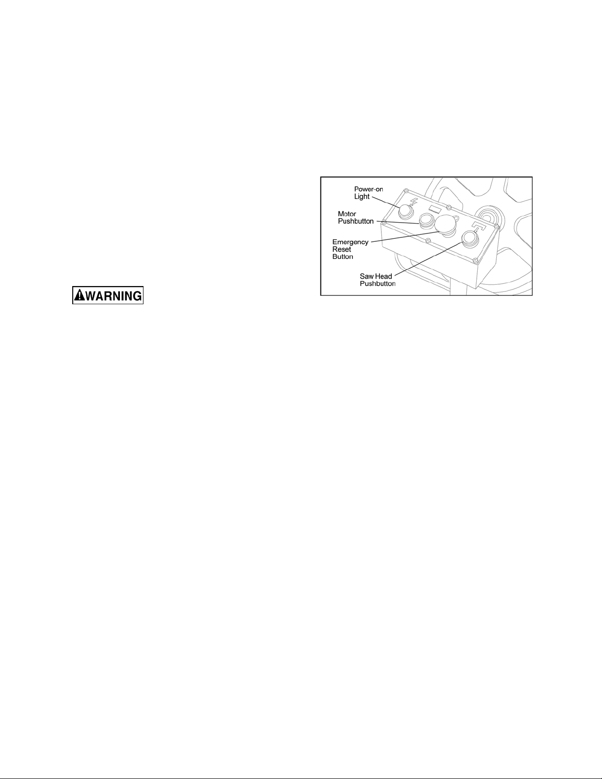
Figur e 1: Control panel
1. A power-on light is provided on the left side of
the control panel. The power-on light indicates
when power is connected to the machine.
2. An emergency stop button is provided on the
control panel. The emergency stop button
provides a means to rapidly cut off electrical
power.
3. The saw motor pushbutton switch starts the
saw motor and the E-stop button stops the
saw motor.
4. A green pushbutton switch is provided to the
right of the emergency stop pushbutton. The
pushbutton opens an electro-magnetic valve in
the hydraulic cylinder circuit. Opening the
valves a llows t he saw head to move downward
and put the saw blade in contact with the
workpiece.
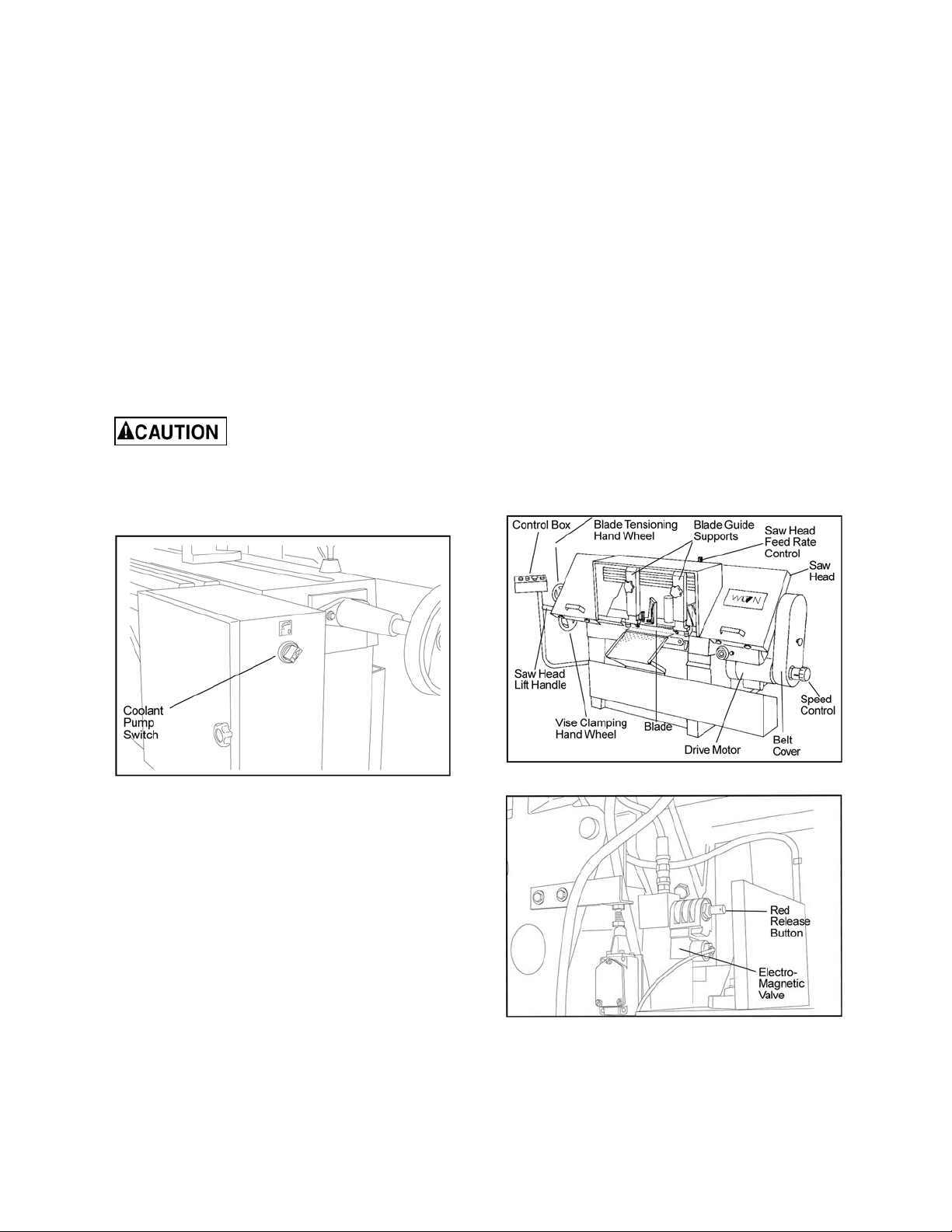
5. A red release button on the electro-magnetic
valve provides a means to lower the saw head
when power to the machine has been
disconnected (see Figure 4) .
6. The rate at which the saw head moves
downward is controlled by a hydraulic feed
rate control located on the top, rear of the saw
head (see Figure 3).
7. A coolant pump switch is provided on the
electrical equipment box on the back of the
machine (see figur e 2).
8.2 Set t ing blade speed
1. The blade speed is controlled by an
adjustment mechanism on the right end of the
saw. Speed increases when the adjustment
8
Page 9
knob is turned counterclockwise. Speed
decreases when the knob i s turned clockwise.
2. A placard on the drive belt guard provides
recommended speeds for v arious ma teria ls.
3. A speed indicator is provided on the barrel of
the adjustment mechanism. The indicator
provides speed indications in feet per minute
and meters per minute. (The meters per
minute values are shown in parenthesis on the
indicator.)
4. The feed rates on the placard are expressed in
me ters pe r minute . The f eed rate grad uatio ns
available on the indicator may not match the
recommended feed rate. An approximate
speed may therefore be required. For
example, to set a speed rate of 25 meters per
minute, the indicator would be set about
midway between 21 meters-per-minute and
the 30 meter s-per- m inute gr aduation s.
To change speed, the saw
motor must be ope rating.
5. Turn the speed adjustment knob to the desired
rate setting as determined by the material
being cut.
8.4 Controlling the cut: Hydraulic
feed contro l
The weight of the saw arm provides all the force
needed to move the saw blade through the
workpiece. In fact, if the full weight of the arm is
allow ed to make the cut, rapid bl ade wear and poor
cutting accuracy will result. A hydraulic feed control
is provided that gives the operator a means to
control the speed and efficiency of cut ting.
The hydraulic cylinder is attached between the saw
base and the saw head. The hydraulic cylinder
resi sts movement of t he saw head in th e downward
direction. However, the hydraulic cyl inder offers no
resi stance when the saw head is ra ised upward.
The amount of downward force can be controlled
by using the feed rate control valve. When the
valve is opened slightly, the saw head will move
downward. The further the valve is opened, the
fast er the saw head will mov e downward.
The feed control is adjusted by the operator until
the saw is operating efficiently. This is usually
determined by observing the chip formation. (See
section 8.5, Evaluating cutting efficiency, fo r more
information.)
Figur e 2: Coolant pump swit ch
8.3 Rai si ng/lo wering saw head
1. Lift the saw head using the handle on the far
left side of the saw head.
2. To lower the saw head, press the green
pushbutton on the right side of the control
panel.
3. To adjust the feed rate, adjust the feed rate
control valve knob on the top of the saw head
(see Fi gure 3) .
4. To lower the saw head with power off, pull and
turn the red knob (manual override) on the
elect ro-magnetic valve ( see Figur e 4).
Figur e 4: Lowering head with p ower off
Figur e 3: Controls
9
Page 10
8.5 Evaluating cut ting effici ency
Is the blade cutting efficiently? The best way to
determine this is to observe the chips formed by
the cut ting blade.
If the chip formation is powdery, then the feed rate
is much too light, or the bla de is dull.
If the chips formed are curled, but colored — that
is, eith er blue or straw-colored fr om heat gen erated
durin g the cut — then th e feed rat e is too h igh.
If the c hips are sli ghtl y cu rle d and ar e not c o lor ed
by heat — the blade is sufficiently sharp and is
cutting at its most efficient rat e.
8.6 Blade selecti on
The cut-off saw is provided with a saw blade that is
adequate for a variety of cut-off jobs on a variety of
common materials. A 4/6 vari tooth bi-metal blade
(5674011) and a 6/10 vari tooth bi-metal blade
(5674021) are ava il able from JET.
See sect. 8.2, Setting blade speed, for the
recommended speeds for various materials. These
selections , whi le appropriate for many shop cutting
needs, do not encompass the wide variety of
blades of special configuration (tooth pitch and set)
and special alloys for cutting unusual or exotic
materials.
A c oar se b lad e co uld be us ed fo r a s ol id st eel b ar
but a finer tooth blade would be used on a thin-wall
tube. In general, the blade choice is determined by
the thickness of the material; the thinner the
materi al, the finer the tooth pitch.
A minimum of three teeth should be on the wor k
piece at all times for proper cutting. The blade
and workpiece ca n be damaged if t he teet h are
so far apart that they straddle the wor kpiece.
For very high production on cutting of special
materials, or to cut hard-to-cut materials such as
stainless steel, tool steel, or titanium, you can
ask your industrial distributor for more specific
blade recommendat ions. Also, the supplier w ho
provides the workpiece material should be
prepared to provide you with very specific
instructions regarding the best blade (and
coolant or cutting fluid, if needed) for the
material and shape supplied.
1. Clamp a round section workpiece in the vise.
The workpiece should be 2 inches or larger in
diameter.
2. Set the saw on low speed. Start the cut with a
very light feed rate.
3. When the saw has completed 1/3 of the cut,
increase the feed rate slightly and allow the
saw to complete the cut.
4. K eep the sam e hydr aulic cylind er s etting and
begin a second cut on the same or similar
workpiece.
5. When the blade has completed about 1/3 of
the cut, increase the feed rate. Watch the chip
formation until cutting is at its most efficient
rate and allow the saw to complete the cut
(see sect. 8.5, Evaluating blade efficiency).
The bl ade is no w cons ide red read y fo r regul ar
service.
9.0 Work setup
9.1 Securing wo rkpiece fo r square
cuts
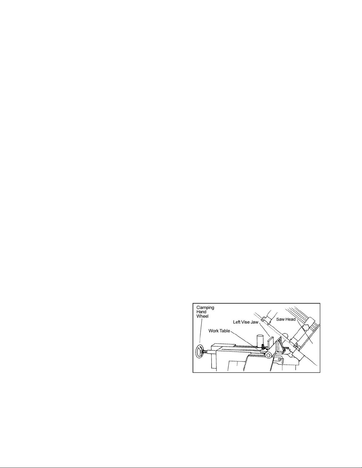
1. Raise the saw head (refer to Figure 5).
2. Slide the left vise jaw f ar enough to the left to
allow the workpi ece to be pla ced in t he vise.
3. Place the workpiece on the work table. If the
workpiece is long, provide support at the other
end. It may also be necessary to provide
additional downward clamping to hold the
workpiece securely on the work table.
4. Turn clamping hand wheel clockwise to clamp
the workpiece in position against the fixed
(right) vise jaw.
5. After completing the cut, turn the clamping
hand wheel counterclockwise and slide the left
jaw away from th e workpiece.
8.7 Bl ade break-in procedures
New blades are very sharp a nd, therefore, have
a tooth geometry which is easily damaged if a
careful break-in procedure is not followed.
Consult the blade manufacturer’s literature for
break-in of spec ific blades o n specific materials.
However, the following procedure will be
adequate for br eak- in of JET-supplied blades on
lower alloy ferrous materials.
Figure 5: Securing workpiece
9.2 Ad justing vise for an gl e cuts
1. Referring to Figure 6, loosen the angle locking
screw and the pi vot screw on the le ft vise jaw.
2. Turn the locking handle on the round, anglesetting block counterclockwise to unlock the
10
Page 11

block. Slide the block until the pointer on the
block is aligned with desired angle (see Figure
7). Tighten the locking handle to set the angle.
3. Set the workpiece in the vise. Put the front end
of the workpiece against the corner of the right
vise jaw. Put the rear end of the workpiece
against the angle-setting block.
4. Turn clamping hand wheel clockwise until the
left vise jaw is parallel with the workpiece.
Tighten the pivot screw and angle locking
screw on the left vise jaw. Clamp the
workpi ece in position.
5. After completing the cut, turn the clamping
hand wheel counterclockwise and slide the left
jaw away from th e workpiece.
Figur e 6: Adjust ing vise
2. Ti ghten “wi ng” scr ew to secur e rod in place.
3. I nstall the stop post in the channel on the back
of the stop L-bracket. Install the locking lever
in the threaded hole in the stop post. Snug-up
the locking lever.
4. Install the locking knob in the hole in the side
of th e stop L-bra cket.
5. Slide the assembled stop L-bracket onto the
stop rod. Position the stop post against the
work piece and tighten the knob in the stop Lbracket. The stop post can be moved left or
right as required to place it against the work
piece.
10.0 Startin g th e Saw
Never operate saw without
blade cover s in place and se cured.
Make sure blade is not in
co ntact with work piece wh en m otor is star ted.
Do not drop the saw head on workpiece or
forc e saw blade through the workpiece.
1. Raise the saw head. With the saw motor off,
pull the red release button on the electromagnetic valve and check the rate at which the
saw he ad lower s .
Figur e 7: Angle setting b lock
9.3 Installation and adjustment of
wo rk st op
Figure 5: The w ork st op is used to set up the
saw fo r mak ing m ultip le c uts o f t he sam e le ngt h
(see figure 8). I nstal l and adjust t he wor k stop
as follows:
Figur e 8: Work stop
1. I nsert the end of the stop rod in the hole in the
fron t ri ght side of the work table.
2. Raise sa w head. Push in r ed release but ton.
3. Clamp the workpiece in the vise. (See Figure
9 for ex amples of w orkpieces in the vise.)
4. Be sure the blade is not in contact with the
Figur e 9: Placing w orkpi eces in vise
workpi ece when the motor is star ted.
11
Page 12

5. Start t he mo tor and allow t he saw to c om e up
to speed.
6. Slowly set the saw down onto the workpiece.
Adjust cutting speed with feed rate control
valve.
7. DO NOT DROP THE SAW HEAD OR FORCE
THE CUT. Let the weight of the saw head
provide the cutting force.
8. The saw will auto maticall y shut of f at the end
of the cut.
10.1 Coolant flow
The coolant pump must be
submerged before o p erating to prevent d am age
to t he pum p.
1. The blade guides are fitted with coolant
fittings. Coolant is provided to the fittings
thro ugh interc onnec ting tub ing . The co olant is
dispensed directly onto the saw blade.
2. Adjust the coolant flow valves on the top, rear
of the saw head as required to provide the
desired flow. The flow should be no more than
the blade can draw into the workpiece by
blade movement.
3. The coolant flow can be stopped in two ways:
1) By using the coolant pump switch on the
elect rica l equi pm ent box, or
2) By closing the coolant flow valves on the
top, rear of the saw h ead.
To change the blade, refer to sect. 12.3, Changing
blades. To adjust blade tracking, refer to the
following procedures.
11.1 Bl ad e t racking adjust ment
Blade tracking has been tested at the factory.
Adjustment is rarely required when the blade is
used properly or if the blade is correctly welded.
(See Figure 10 for location of blade tracking
adjustment screws.)
Figur e 10: Blade track ing and tensionin g
11.2 Factory or field procedure
1. Raise the saw head enough to allow the saw
motor to operate.
2. Loosen four knobs securing the blade cover.
Lift the cover and swing it backward.
3. Remove the blade guard mounted on the left
blade gui de support.
10.2 Coolant mixture and quantity
The general purpose coolant is a mixture of water
soluble oil and water. Mix one part of soluble oil
(TR IM SOL ) to t e n part s of wate r (one quart o il , ten
quarts of water). Eleven quarts of coolant are
required for th e coolant pu m p to operate properly .
There are numerous coolants on the market that
are formulated for special applications. Consult
your local distributor for details in the event you
have a long range production task, or are required
to cut some of the more exotic materials.
11.0 Adjustments
The efficient operation of the cut-off saw is
dependent upon the condition of the saw blade. If
the performance of the saw begins to deteriorate,
the first item that you should ch eck is th e blade.
If a new blade does not restore the machine’s
cutting accuracy and quality, refer to sect. 13.0,
Troubleshooting (or the blade manufacturer’s
guide) for c ond itions to c onside r and ad justme nts
that can be m ade to increase the life of the blade.
4. Remove b oth blade guide bearing bra ckets.
NOTE: Maintain proper tension at all times
using the blade tensio ning mechanism.
5. Loosen the center locking screws in all three
hex adjustment screws on the blade tensioning
mechanism (see Figure 10).
While performing the
following, keep the blade
from rubbing excessively on the shoulder of
the wheel. Excessive rubbing will damage the
wheel and/or the blade.
6. Start the saw. Slowly turn the single hex
adjustment screw at the rear of the tracking
me chanis m to tilt the idle r whee l. Do no t turn
either of the other two adjustment screws.
Turn the adjustment screw until the blade is
touchi ng the shoul der of th e idler w heel.
NOTE: Turning the screw inward causes the blade
to move toward the shoulder of the wheel. Turning
the screw outward causes the blade to move away
from t he shoul der.
7. Turn the single hex adjustment screw so the
blade sta rts t o m ove away from the shoulder of
wheel – then turn the single hex adjustment
12
Page 13

screw in the other direction so the blade stops,
then moves slowly tow ard the sh oulder .
Keep fingers clear of blade
and wheel to avoid injury.
8. Turn t he single hex adjustment screw to stop
the motion of the blade on the wheel as it gets
closer to the wheel shoulder. Put a 6-inch
length of paper between the blade and the
wheel as shown in Figure 11. The paper
should not be cut as it passes between the
wheel shoul der and the bla de.
Turn the single hex adjustment screw a
9.
small amount. Repeat the insertion of the
paper between the wheel shoulder and the
blade until the paper is cut in two pieces.
13. Install the two blade guide bearing brackets.
Position the guides so the bearings just touc h
the bla de.
14. In stall the left blade guard.
15. Close the saw head cover. Tighten all four
knobs.
11.3 Bl ad e guide bearing adjustment
Proper adjustment of the blade guide bearings is
critical to efficient operation of the cut-off saw. The
blade guide bearings are adjusted at the factory.
They should rarely require adjustment. When
adjustment is required, adjust immediately. Failure
to maintain proper blade adjustment may cause
seri ous blade da m age or inaccurat e cuts.
It is always better to try a new blade when cutting
performance is poor. If performance remains poor
after changing the blade, make the necessary
adjustments.
If a new blade does not correct the problem, check
the blade guides for proper spacing. For most
efficient operation and maximum accuracy, provide
0.001 inch clearance between the blade and the
guide bearings. The bearings will still turn freely
with this clearance. If the clearan ce is incorrect, the
blade may track off the dri ve wheel.
Figure 11: Checking blade-to-wheel clearance
using paper strips
NOTE: Y ou may have to repeat the check wit h
the paper several times bef or e the blade a nd t he
shoulder cuts the paper into tw o pieces. Do not
hurry the adjustment. Patience and accuracy
here will pay off with better, more accurate,
quieter cutting and much longer machine and
blade life.
10. When the paper is cut, turn the hex adjustment
screw slightly in the counterclockwise
direction. This assures that the blade is not
touchi ng the shoul der of th e w heel.
11. Shut off the saw.
Check the blade to make sur e
the welded section is the same thi ckness as the
rest of the blade. If the blade is thicker at the
weld, the guide bearings may be damaged.
If required, adjust the guide bearings as follows:
1. The inner guide bearing is mounted on a
concentr ic bushin g and cannot be adjusted.
2. The outer guide bearing (closest to the
operator) is mounted on an eccentric bushing
and can be adjusted.
3. Hold the bushing wi th a 3/4-inch wrench and
loosen the center locking screw with an Allen
wrench (see Figure 12).
12. Hold the hex adjustment screws with a wrench
and tighten the center locking screws. Make
sure the hex adjustment screws do not move
while tightening the center screws.
Figur e 12: Adjustment of guide bearings
13
Page 14

Figur e 13: Blade- to-bearing orientat ion
4. Position the bearing by turning the bushing.
Set the clearance at approximately 0.001 inch.
(The blade should be in a vertical position
between t he bearings. (See Fi gure 13.)
5. Tighten the center locking screw with an Allen
wrench while holding the eccentric bushing in
posit ion with the 3/4- inch wrench.
6. Use the same procedure to adjust the other
guide bear ing.
7. When the adjustment is correct, the guide
bearings should rotate freely with slight
pressur e of the finger (wi th the bl ade stopped).
8. Adjust bla de-edge beari ngs so they just tou ch
the back edge of the blade (see Figure 18).
11.4 T est cuttin g to verify ad justmen t
accuracy
Test cuts can be used to determine whether or not
you have adjusted the blade accurately. Use 2inch ro und bar sto c k to p e rf o rm thes e te s t cuts, as
follows:
sho uld b e no mo re than 0 .003 inch, per side,
per i nch of stock diameter.
Figur e 14: Cutting a te st disc
11.5 L i mit swi t ch ad justmen t
1. The limit switch is provided to shut off the saw
motor when the workpiece is cut th rough.
2. To set the limit switch, loosen the jam nut on
the lim it swi tch stop ( Figure 15).
3. Adjust the stop as required and retighten jam
nut.
1. With the bar stock securely clamped in the
vise, make a cut through the bar stock. (See
Figure 14.)
2. Mark the top of the bar stock.
3. Move the bar stock about 1/4-inch past the
blade so you can begin a second cut.
4. Rotate the bar stock 180 degrees so the mark
you made is now at the bottom of the cut .
5. Mak e a cut through the bar st ock.
6. Use a micrometer to measure the thickness
variation of the disk you have cut from the bar
stock. Measure at the top and bottom of the
disk.
7. The saw blade can be considered correctly
adjusted when the variation measure is no
more than 0.012 inch across the face of the
disk.
8. If you do not have a piece of 2-inch bar stock
available for a test cut, use a larger diameter
test piece rather than a smaller one. The
maximum thickness variation on any test piece
Figur e 15: Limit switch adjustm ent
12.0 Maintenance
12.1 Cleaning
1. Clean off any preservative on machine
surfaces.
2. A fte r cleaning , co at the machine d s urface s of
the cut-off saw with a medium consistency
machine oil. Repeat the oil coating process at
least every six months.
14
Page 15

3. C lean up acc umul ate d s aw c utt ing s af te r use .
Make sure the le ad scre w is kept free of saw
cuttings and other materi al that would cause
damage.
4. Clean the chip sludge from the coolant tank.
The frequency should be determined by how
often the saw is used.
12.2 Lubrication
Lubrica te th e follow ing components at the specified
frequ encies a nd using th e lubri cants as defined:
1. Ball bearings: the bearings are lubricated and
sealed—periodic lubrication is n ot required.
2. Blade guide bearing: The bearings are
lubricated and sealed—lubrication is not
required. Inspect periodically.
3. Idler wheel bushing: The bearings are
lubricated and sealed—lubrication is not
required. Inspect periodically.
4. Lead screw bearing housing: Lubricate with
light oil monthly (see exploded figure, section
14.1.1).
5. Lead screw: Lubricate with light oil monthly
(see exploded figure, section 14.1. 1).
6. Hydraulic cylinder pivot: Lubricate with light oil
every 6 months (see exploded figure, section
14.1.1).
7. Blade tension screw: Lubricate with grease
every 6 months (see exploded figure, section
14.2.1).
8. Blade brush bearing: Lubricate with light oil
monthly (see expl oded figure, section 14.2. 1).
9. Gear box: check oil on ce a year.
10. Change coolant on a frequency appropriate to
the type of coolant being used. Oil based
coolants can sour. Refer to the coolant
supplier’s instructions for change frequ ency.
11. Coolant tank: Clean every 6 months or as
required.
12.3 Changing blades
1. Turn the blade tensioning hand wheel
clockwise to relieve tension on the blade.
Loosen the blade enough to remove the blade
from the idler and drive wheels. Remove the
blade from b etween the bla de guides.
2. Install the new blade between the blade guide
bearings and the carbide blade guides. Install
the bla de over th e drive and i dler wheels.
3. Turn the blade tensioning hand wheel
counterclockwise to tighten the blade. Tighten
the blade until the blade tension indicator
reads 2000 pounds.
4. Operate the saw at low speed and observe the
tracking of the blade. If tracking needs to be
adjusted, refer to sect. 11.1, Blade tracking
adjustment.
5. Adjust the bearings on the upper edge of the
blade until they just contact the blade (see
Figure 18).
6. Check the guide bearings and the carbide
guides to make sure they are just contacting
the sides o f the blade.
7. I nstall the left blade guard making sure there is
ample cleara nce with the blade.
8. Make a te st c ut to make s ure the b lade tracks
properly during operation. Adjust tracking as
required (see sect. 11.1, Blade tracking
adjustment).
12.4 Changing drive belt
1. Disconnect the electrical power source from
the cut-off saw to prevent any possibility of
accidental motor start-up.
2. Set the arm at the full horizontal position.
3. Remove the knob on the drive belt cover.
Remove the drive belt cover to expose the Vbelt and pull eys.
4. Remove two screws, nuts, and washers from
back of saw head support. Push on the motor
support bracket to pivot the motor upward to
loosen the tension on the bel t.
5. Remove the worn belt.
Shut off all electrical power to
machine.
1. Loosen four knobs securing the blade cover.
Lift the cover and swing it backward.
2. Remove the blade guard mounted to the left
blade gui de support.
Always wear leather gloves
when handling saw blade to avoid injury from
saw teeth.
6. Put the replacement belt in the pulleys. Allow
the motor to piv ot downward.
7. Install the two screws, nuts, and washers in
back of saw head support and through the
motor support bracket.
8. Install the drive belt cover. Install and tig hten
the knob on th e drive belt cover.
15
Page 16

12.5 Replacing drive motor
1. Disconnect the motor from all electrical power.
Unpl ug the m oto r if it is p lugge d into a s ocke t.
Shut o ff the po we r to the branch and remove
the co nnectio n to the junctio n box if the mo tor
is har d wired to the branch .
2. Remove the drive belt from the drive motor
pulley (see sect. 12.4, Changing drive belt).
3. Remove motor pulley.
4. Open the motor junction box and disconnect
the power cord wires from their terminals.
5. Remove the nuts, washers and bolts that
secure th e m otor t o the mounting plate.
6. 6. Installation of a new motor is a reversal of
the above steps.
12.6 Adjusting counterbalance
spring
1. The counterbalance spring is located at the
right, rear of the saw head. The
counterbalance spring is used to adjust the
amount of down force the saw head puts on
the workpiece when the feed rate control valve
is fully open.
2. Raise the saw arm to its full upright position
and lock it in position.
3. To adjust t he tensi on on the spring, l oosen the
two nuts on the threaded rod of the spring
pivot post. Adjust the tension as required.
12.8 Rep lacing idler wh eel or idl er
bearing
1. Remove the saw blade (see sect. 12.3,
Changing blades).
2. Remove t he screw, spring washer, an d washer
from the idler shaft.
3. Remove the idler wheel. Remove the bearing
from t he idler wheel.
4. Inspection: Examine the drive edge and
shoulder of the idler wheel for damage.
Replace th e wheel if damaged.
5. Inspect bearings for damage and smooth
operation. Replace if faul ty.
6. I nstall the bearing in the idler wheel. Install the
idl er wheel on t he idl er shaft .
7. I nstall the screw, spring washer and washer in
the idler shaft.
8. Install the bla de (sect. 12.3, Changi ng bla des).
12.9 Ad j ustin g b lade guides
The cut-off saw has adjustable blade guide
supports (see Figure 16). The blade guide
supports allow you to set the blade guides for
varyin g widths of workpi eces.
To make accurate cuts and prolong blade life, the
blade guide supports should be set to just clear the
workpi ece to be cut.
4. Tighten the two nuts against the pivot post.
5. The saw can now be retur ned to service.
12.7 Replacing drive wheel
1. Remove the blade (see sect. 12.3, Changing
blades).
2. Remove t he screw, spring washer, an d washer
from t he speed re ducer shaft.
3. Pull the wheel from the speed reducer shaft.
Remove the drive key from the speed reducer
shaft.
4. Inspection: Examine drive edge and shoulder
of the wheel for damage. Replace the wheel if
damaged.
5. Install the key in the keyway in the speed
reducer shaft. Align the keyway in the wheel
with the key in the speed reducer shaft.
Reinstall the wheel on the speed reducer
shaft.
6. I nstall the screw, spring washer and washer in
the end of the speed redu cer shaft.
7. Install the blade (see sect. 12.3, Changing
blades).
Figur e 16: Blade guid e supports
1. Loosen the knob on the blade guide support
and slide the guide left or right as required.
Repeat for the ot her blade guide.
2. Set the blade guide supports as required to
accommodate the width/diameter of the
workpiece. The blade guides should be
positioned so the guides do not contact the
workpiece as the saw head moves downward
throu gh the workpiece.
16
Page 17

12.10 Rep lacing carbide blade gu ide
Refer to Figure 17.
1. Remove the cap screw and remove the
carbide gu ide. Di scard th e carbi de guide.
2. Install the replacement carbide guide on the
guide bearing support. Install the cap screw.
Set the guide so it just contacts the side of the
saw blade.
3. Using a mac hinist's square, check squareness
of th e blade t o the tabl e.
Figur e 17: Carbid e blade guide s and guide
bearings
12.11 Rep lacing guide b earings
Referring to Figure 17, remove the cap screw from
the bearing being replaced. Separate the bushing
and cap screw from the bearing. Discard the
bearing.
NOTE: There is a light press fit between the
bearin g and th e bushing.
2. Insert the capscrew into the new bearing.
Replace the spring washer onto the capscrew
and re-install into the floating block.
3. If re-adjustment is necessary, loosen the pivot
cap screw and m ove the floating b lock s o that
the blade edge is close to the guide support,
but cannot touch the bottom surface of it when
the saw blade is cutting a workpi ece.
Figur e 18: Blade ed ge bearing replac ement
12.13 Replacing wire brush
1. Loosen four knobs securing the blade cover.
Lift the cover and swing it backward.
2. Remove the attaching screw, spring washer
and washer. Remove and discard the brush
(see Fi gure 19) .
3. Install replacement brush and secure with
screw, spr ing washer and washer.
4. Close the blade cover and secure with four
knobs.
1. Install bushing in replacement bearing. Install
cap screw through bushing and into guide
support.
2. I f the bearing being replaced is on an eccentric
bushing, install the bearing on the operator
side of the blade.
3. Turn the eccentric bushing in the guide
support u ntil the bearing contacts the blade.
12.12 Rep lacing blade edge bearin gs
1. Remove the capscrew from the blade edge
bearing being replaced and discard the
bearing. Be careful not to lose the spring
washer that separates the bearing from the
floa tin g block ( see Figure 18).
Figur e 19: Wire bru sh
17
Page 18

13.0 Troubleshooting the J-7020/7040 Band Saw s
A
A
A
A
A
A
Symptom Possible Cause Correction
Excessiv e blade
breakage
Premature blade
dulling
Bad cu ts
(out-of-square)
Materi al loose in vise. Clamp work securely .
Incor rect speed or fee d. Check ma chinist’ s handbook for
speed/feed appropr iate for the mater ial
being cut.
Teeth too coa rse for m aterial. Check machi nist’s handbook for
recommended bl ade type.
Incor rect bl ade tension.
Saw blade is in contact with
workpiece before the saw is sta rted.
Blade ru bs on the wheel fl ange.
Misaligned guides.
Cracking at we ld. Lo nger anneal i ng cycle .
Blade teeth too coarse. Use a fin er toot h blade.
Blade speed t oo high . Try a low er blade speed.
Inadequate feed pressure. Decrease spring tension.
Hard spots i n workpiece or scale
on/in workpiece.
Work hardenin g of material
(especia lly stainless st eel).
Insuffici ent blade tension. Incr ease tension to proper level.
Operati ng saw with out pressure on
workpiece.
Workpiece not squ are with blade.
Feed pressure t oo fast. Decrease pressu re.
Guide bearin gs not adjusted
properly.
Inadequate blade tension. Gradually increase blade tension.
Span between the tw o blade guides
too wide.
Dull blade. Replace bla de.
djust blade tension to the poin t where th e
blade ju st does not slip on th e wheel.
Start the motor before placin g the saw on
the workpiece.
djust blade tr acking.
djust gu ides.
Incr ease feed pr essure ( hard spots).
Reduce speed, increa se feed pre ssure
(scale).
Incr ease feed pr essure by reducing sprin g
tension.
Do not run blade at idle in/on material.
djust vise so it is square wi th the blade.
(Always cla m p work tightly in vise.)
djust gu ide bear ing cl earance to 0.001
inch ( 0 .002 in ch maximum ).
Move blade gu ide bar closer to work.
Incor rect bl ade speed. Check blade speed.
Blade gui de assembly is loose. Tighten blade guide a ssem bly.
Blade gui de bearing assembly loos e. Tight en blade gui de bearing assembly.
Blade tracks too far away fr om wheel
flanges.
Guide bearing worn. Replace worn bearing.
Bad cuts ( rough) Blade speed t oo high for feed
pressure.
Blade is too coarse. Replace wi th fi ner blade.
Blade is twisting
Blade is binding in the cut. D ecrease feed pres sure.
Blade ten sion too high. Decrease tension on blade.
djust blade tr acking.
Reduce blade speed and feed pressure.
18
Page 19

Symptom Possible Cause Correction
A
A
Unus ual wear o n
side/ back of blade
Teeth missi ng/ripped
from bl ade
Motor ru nnin g too hot Blade ten sion t oo high. Reduce t ensi on on blade.
No coolant flow Pump motor is burned ou t. Repla ce pump.
Blade gui des worn Replace bla de guides.
Blade gui de bearings not adjusted.
Blade gui de beari ng brack et is loose. Tigh ten blade guide bearing bra cket.
Blade tooth pitch too coarse for
workpiece.
Feed too slow; feed too fa st. Incr ease feed pr essure and/or blade
Workpiece vibrati ng. Clamp workpiece secur ely.
Gullets loading up with chips. Use blade with a coarse t ooth pitch —
Dri ve belt tension too high . Reduce tension on dri ve belt.
Blade too coa rse for workpi ece
(e sp ecia lly w ith tubular stock).
Blade too fine for workpiece
(esp ec ially with heavie r, so f t
material).
Speed reducer gea rs require
lubrication.
Screen/filter on pump is clogged. Clean screen/ fi lter .
Impeller is loose. Tighten impeller.
djust blade guide bear ings.
Use blade with finer tooth pitch.
speed.
reduce fee d pressure.
Brush blade to remove chips.
Use blade with fine t ooth pi tch.
Use blade with coarse tooth pit ch.
Check speed reducer.
Excessive speed
reducer n oise/v ibration
Coolant level too low.
V-belt is too tight. Reset V-belt tension.
Countering spring not tensioned
properly.
dd coolant to reserv oir.
Increase spring tension.
14.0 Repla cement Parts
Replacement parts are listed on the following pages. To order parts or reach our service department, call 1800-274-6848 Monday through Friday (see our website for business hours, www.waltermeier.com). Having the
Model Number and Serial Number of your machine available when you call will allow us to se rve you quickly
and accurat e ly.
19
Page 20

14.1.1 Base (J-7020/70 40) – E xploded View
20
Page 21

14.1.2 Base (J-7020/70 40) – P art s List
Index No Part No Description Size Qty
1 .............. J-5712251 ...............Foot, Left............................................................................................ 1
2 .............. J-5712261 ...............Foot, Right ......................................................................................... 1
3 .............. J-5712271 ...............Coolant Reservoir ............................................................................... 1
3-1 ........... 5519485 ..................Stopper (PT 3/8") ................................................................................ 1
4 .............. J-5712281 ...............Coolant Pump 115/220, 1-Phase ......................................................... 1
................ J-5712921A .............Coolant Pump 220/440, 3-Phase ......................................................... 1
4-1 ........... 5519486 ..................Adapter (PT 3/8") ................................................................................ 1
5 .............. 5712291 ..................Pan Head Screw ..............................................1/4" x 5/8”................... 2
7A............ 5512101 ..................Filter Screen w/Screw ......................................................................... 1
8 .............. 5712331 ..................Hose ................................................................5/16" .......................... 1
8-1 ........... 5519487 ..................Hose Clamp ....................................................................................... 6
9 .............. 5712341 ..................Chip Pan ............................................................................................ 1
10 ............ J-5712351 ...............Pump Bracket ..................................................................................... 1
11 ............ J-5712361 ...............Work Table......................................................................................... 1
11-1 ......... 5519491 ..................Label, Made in Taiwan ........................................................................ 1
11-2 ......... 5519492 ..................Rivet ................................................................2mm ........................ 14
11-3 ......... TS-1482011 ............Hex Cap Screw ................................................M6x 10....................... 1
11-4 ......... TS-1550041 ............Wash er ............................................................M6 ............................. 1
11-5 ......... TS-2361061 ............Spring Washer..................................................M6 ............................. 1
12 ............ 5712371 ..................Screw ..............................................................1/4" x 7/8" .................. 1
13 ............ 5712381 ..................Hex Cap Screw ................................................1/2" x 1" ..................... 4
13-1 ......... 5712391 ..................Spring Washer..................................................1/2" ............................ 4
14 ............ 5712641 ..................Washer ............................................................1/2" ............................ 4
15 ............ J-5712411 ...............Electrical Control Box .......................................................................... 1
15-1 ......... 5519488 ..................Hex Cap Screw ................................................5/16" x 3/4"................. 3
15-2 ......... TS-0720081 ............Spring Washer..................................................5/16" .......................... 3
15-3 ....... TS-0680031 ............Wash er ............................................................5/16 " .......................... 3
15-4 ......... 5519501 ..................Label, P ump Switch ............................................................................ 1
16 ............ 5712421 ..................Work Stop Bracket .............................................................................. 1
17 ............ 5712431 .................Work Stop Rod .................................................................................. 1
18 ............ 5712441 ..................Locking Screw .................................................................................... 1
19 ............ 5712451 ..................Screw ..............................................................1/2" ............................ 1
20 ............ J-5712461 ...............Pump Cover ....................................................................................... 1
21 ............ 5712471 ..................Hand Wheel Assembly ........................................................................ 1
21-1 ......... 5519494 ..................Set Scre w ........................................................5/16 " x1/2" .................. 1
22 ............ J-5712481 ...............Lead Screw Br acket ............................................................................ 1
23 ............ 5712491 ..................Screw ..............................................................5/16" x 1/4"................. 2
23-1 ......... TS-0720081 ............Spring Washer..................................................5/16" .......................... 2
23-2 ......... TS-0680031 ............Wash er ............................................................5/16 " .......................... 2
24 ............ 5712511 ..................Vise Lead Screw ................................................................................. 1
24-1 ......... 5519710 ..................Key ..................................................................5x5x20mm ................. 1
24A.......... 5514806 ..................Collar with Pin .................................................................................... 1
25 ............ 5712521 ..................Lead Scr ew Bracket ............................................................................ 1
26 ............ 5712531 ..................Acme Nut ........................................................................................... 1
27 ........... 5712541 ..................Button ................................................................................................ 1
28 ............ 5712551 ..................Retainer ............................................................................................. 2
29 ............ 5712561 ..................Screw ..............................................................M5 x 8........................ 1
30 ............ 5712571 ..................Needle Bearing.................................................CB3020...................... 2
30-1 ......... 5519495 ..................Bu shin g............................................................4mm .......................... 1
30-2 ......... 5519496 ..................Bush ................................................................2mm .......................... 1
31 ............ 5712581 ..................Washer ............................................................1/2" ............................ 2
32 ............ 5712591 ..................Pivot Shaft ......................................................................................... 1
33 ............ J-5712611 ...............Pivot Bracket ...................................................................................... 1
34 ............ 5712621 ..................Screw ..............................................................1/2" x 3/4" .................. 2
35 ............ 5712631 ..................Retaining Ring ..................................................S12............................ 1
21
Page 22

Index No Part No Description Size Qty
36 ............ 5712641 ..................Washer ............................................................1/2" ............................ 2
37 ............ 5712651 ..................Spring Pull Pivot ................................................................................. 1
39 ............ 5712671 ..................Screw ..............................................................5/8" x 1" ..................... 2
40 ............ 5712681 ..................Regulating Seat .................................................................................. 1
40-1 ......... TS-0051021 ............Hex Cap Screw ................................................5/16" x 5/8"................. 2
40-2 ......... TS-0720081 ............Spring Washer..................................................5/16" .......................... 2
40-3 ........ TS-0680031 ...........Wash er ............................................................5/16 " .......................... 2
41 ............ 5712691 ..................Nut ..................................................................3/8" ............................ 1
42 ............ 5712711 ..................Screw ..............................................................3/8 "x 1" ...................... 1
43 ............ 5712721 ..................Protractor Stop Block .......................................................................... 1
44 ............ 5712731 ..................Screw ..............................................................M6 x 12 ...................... 4
45 ............ 5712741 ..................Limit Switch ........................................................................................ 1
46 ............ 5712751 ..................Limit Switch Bracket............................................................................ 1
46-1 ......... TS-0051021 ............Hex Cap Screw ................................................5/16" x 5/8"................. 4
46-2 ......... TS-0720081 ............Spring Washer..................................................5/16" .......................... 4
46-3 ......... TS-0680031 ............Wash er ............................................................5/16 " .......................... 4
47 ............ 5712761 ..................Screw ..............................................................3/8" x 1" ..................... 3
48 ............ 5712771 ..................Spring Washer..................................................3/8" ............................ 3
49 ............ 5712781 ..................Locking Ha ndle................................................................................... 1
50 ............ 5712791 ..................Washer ............................................................1/2" ............................ 1
51 ............ 5511502* ................Hydraulic Cylinder Assembly .............................2-1/2 in....................... 1
................ 5712811** ...............Hydraulic Cylinder Assembly .............................3-in. ........................... 1
51-1 ......... 5519497 .................Cylinder Pin, Bottom ........................................................................... 1
52 ............ 5712821 ..................Cylinder Pin, Top ................................................................................ 1
53 ............ 5712831 ..................Hydraulic Mounting Plate..................................................................... 1
54 ............ 5712841 ..................Screw .............................................................3/8 " x 2 ...................... 3
55 ............ 5712851 ..................Spring Washer..................................................3/8" ............................ 3
56 ............ 5712861 ..................Washer ............................................................3/8" ............................ 3
57 ............ J-5712871 ...............Protractor Vise Block .......................................................................... 1
58 ........... 5712881 ..................Spring Washer..................................................1/2" ............................ 4
59 ............ 5712891 ..................Spring Pull Rod .................................................................................. 1
60*** ........ 5712911 ..................Spring ..............................................................30mm - Old ................ 2
................ 5519498 ..................Spring ..............................................................32mm - New .............. 1
61 ............ 5712921 ..................Angle Scale ........................................................................................ 1
62 ............ 5712931 ..................Screw ..............................................................1/2" x 1-1/2" ............... 1
63 ............ 5712941 ..................Washer ............................................................1/2" ............................ 2
64 ............ J-5712951 ...............Vise Jaw, Left ..................................................................................... 1
65 ............ 5712961 ..................Screw ..............................................................1/2" x 1-1/2" ............... 1
66 ............ 5712971 ..................Washer ............................................................1/2" ............................ 2
67 ............ J-5712981 ...............Vise Jaw, Right................................................................................... 1
68 ............ 5712991 ..................Screw ..............................................................1/2" x 1-3/4" ............... 2
69 ............ 5713011 ..................Pin ..................................................................................................... 2
70 ............ J-5713021 ...............Electrical Cabinet Door ....................................................................... 1
70-1 ......... 5519499 ..................Knob .................................................................................................. 1
70-2 ......... 5519500 ..................Plan e ................................................................................................. 1
71 ............ 5507542 ..................Overload, Model J- 7020 ( 115V, 1- ph) ................................................... 1
................ 5713031 ..................Overload, Model J-7020 (220V, 1- ph) ................................................... 1
................ 5512660 ..................Overload, Model J-7040 (220V, 3- ph) ................................................... 1
................ 5712661 ..................Overload, Model J-7040 (440V, 3- ph) ................................................... 1
71-1 ......... 5519502A................Fuse Bracket
71-2 ......... 5519503A................Fuse
(serial no. 12020251 and higher)
(serial no. 12020251 and higher)
....................1A............................ 3
........ ................................ 3
71A.......... 5508409 ..................Rel ay ...............................................................115/220 NO.............. 1
72 ............ 5713041 ..................Magnetic Switch ...............................................115/220 1- Phase ........ 1
................ 5713001 ..................Magnetic Switch ...............................................220/440 3-Phase) ..... 1
73 ............ 5713051 ..................Tran s fo rmer ....................................................................................... 1
74 ............ 5713061A................Terminal Strip ..................................................................................... 1
75 ............ 5713071 ..................Spring, Protective Casing .................................................................... 1
76 ............ 5713081 ..................Nut ..................................................................3/8" ............................ 2
22
Page 23

Index No Part No Description Size Qty
77 ............ J-5713091 ...............Protractor Seat ................................................................................... 1
77-1 ......... 5519505 ..................Pin ...................................................................5 x 32mm ................... 2
78 ............ 5713111 ..................Knob .................................................................................................. 1
182 .......... 5713121 ..................Scre w ..............................................................5/16 "x 1/2 ".................. 4
183 .......... TS-0680031 ............Wash er ............................................................5/16 " .......................... 4
184 .......... 5713141 ..................Bra cket .............................................................................................. 1
184-1 ....... TS -0720081 ............Spring Washer..................................................5/16" .......................... 4
185 .......... 5713151 ..................Screw ..............................................................3/8" x 1" ..................... 2
186 .......... 5713161 ..................Washer ............................................................3/8" ............................ 2
186-1 ....... 5713481 ..................Spring Washer..................................................3/8" ............................ 2
186-2 ....... 5519507 ..................Nut ..................................................................3/8" ............................ 2
187 .......... J-5713171 ...............Spring Bracket .................................................................................... 1
188 .......... 5713181 ..................Screw ..............................................................5/16" x 1/2"................. 2
189 .......... 5713191 ..................Wash er ............................................................5/16 " .......................... 2
190 .......... 5713211 ..................Locking Wheel .................................................................................... 1
191 .......... 5713221 ..................Screw ..............................................................1/4" x 3/4" .................. 2
192 .......... J-5713231 ...............Swivel Bushing ................................................................................... 1
192-1 ....... 5519509 ..................C-Ring ............................................................................................. 1
193 .......... 5713241 ..................Spring Washer..................................................1/4" ............................ 4
194 ......... 5713251 ..................Screw ..............................................................1/4" x 3/8" .................. 4
195 .......... J-5713261 ...............Control Column .................................................................................. 1
196 .......... 5713271 ..................Screw ..............................................................1/4" x 3/4" .................. 2
196-1 ....... 5519510 ..................Nut ..................................................................1/4" ............................ 2
197 .......... J-5713281 ...............Swivel Bushing ................................................................................... 1
198 .......... J-5713291 ...............Control Box ........................................................................................ 1
199 .......... 5713311 ..................Control Panel ..................................................................................... 1
200 .......... 5713321 ..................Screw ..............................................................3/16" x 1/4"................. 6
201 .......... 5713331 ................Electric Lamp ..................................................................................... 1
202 .......... 5713341 ..................Start Switch ........................................................................................ 1
203 .......... 5713351 ..................Stop Switch ........................................................................................ 1
204 .......... 5713361 ..................Down Switch ...................................................................................... 1
205 .......... 5713371 ..................E-M Valve complete ............................................................................ 1
215 .......... 5712301 ..................Hex Head Screw ................................................................................. 2
216 .......... 5712401 ..................Flat Washer...................................................................................... 16
217 .......... 5712501 ..................Hex Head Screw ................................................................................ 2
218 .......... 5712601 ..................Lock Washer ..................................................................................... 8
219 .......... 5712701 ..................Hex Nut.............................................................................................. 8
220 .......... 5712801 ..................Shelf .................................................................................................. 1
221 .......... 5712901 ..................Drain Shelf ......................................................................................... 1
228 .......... 5514613 ..................Complete Electrical Panel .................................3-Phase .................... 1
................ 5514616 ..................Complete Electrical Panel .................................1-Phase ..................... 1
229 .......... 5516855 ..................Coolant Pump Switch .......................................................................... 1
................ STRIPE-1-3/4 ..........JET stripe (not shown) .......................................................... sold per ft.
* For S aw Serial No. 704017 and Earlier
** For Saw Serial No. 704018 and Lat er
*** Spring Changed sin ce D ec. '96
Piston/Seal Kit 5512787
E-M valve & coil 5713371A
Not shown in exploded view.
23
Page 24

14.2.1 Head (J-70 20/7040) – E xploded View
24
Page 25

14.2.2 Head (J-70 20/7040) – P arts List
Index No Part No Description Size Qty
79 ............ 5713381 ..................Screw ..............................................................1/4" x 3/8" .................. 4
80 ............ J-5713391 ...............Blade Wheel Cover ............................................................................. 1
80-1 ......... 5518109 ..................Label, JET Logo ................................................................................. 1
80-2 ......... 5519511 ..................Label, Blade Si ze ............................................................................. 1
80-3 ......... 5519512 ..................Label, War ning ................................................................................... 1
81 ............ J-5713411 ...............Wire Brush Guard ............................................................................... 1
82 ............ 5713421 ..................Handl e ............................................................................................... 2
83 ............ 5713431 ..................Washer ............................................................1/2" ............................ 1
84 ............ J-5713831 ...............Drive Wheel ....................................................................................... 1
84-1 ......... 5712641 ..................Washer ............................................................1/2" ............................ 1
85 ............ 5674011 ..................Blade, Bi-Metal .................................................4/6 Vari Tooth............. 1
................ 5674021 ..................Blade, Bi-Metal .................................................6/10 Vari Tooth ........... 1
86 ............ 5713461 ..................Hose .................................................................................................. 1
86-1 ......... 5519515 ..................Hose Clamp ....................................................................................... 1
87 ............ 5713471 ..................Screw ..............................................................3/8" x 1-1/4" ............... 4
88 ............ 5713481 ..................Spring Washer..................................................3/8" ............................ 4
89 ............ 5713491 ..................Screw ..............................................................1/2" x 1-1/4" ............... 4
89-1 ......... 5519671 ..................Setscrew ..........................................................3/8" x 1/2" .................. 2
90 ............ 5713511 ..................Screw ..............................................................5/16" x 1/2"................. 2
91 ............ 5713521 ..................Screw ..............................................................1/4" x 5/8" .................. 4
91-1 ......... 5713661 ..................Washer ............................................................1/4" ............................ 4
92 ............ J-5713531 ...............Blade Wheel Box, Right ...................................................................... 1
92-1 ......... 5519672 ..................Label, Te nsion .................................................................................... 1
92-2 ......... 5519673 ..................Label, ID ............................................................................................ 1
93 ............ J-5713541 ...............Support Bracket Seat .......................................................................... 1
93-1 ......... 5519674 ..................Nut ..................................................................1/2" ............................ 1
93-2 ......... 5519490 ..................Hex Cap Screw ................................................1/2"x 2" ...................... 1
94 ............ J-5713551 ...............Gear Box Assembly ............................................................................ 1
94-1 ......... 5519675 ..................Key ..................................................................7x7x40mm ................. 1
95 ............ 5513734 ..................Key ..................................................................7 mm ......................... 1
96 ............ J-5713571 ...............Pulley Cover ....................................................................................... 1
96-1 ......... 5519676 ..................Knob .................................................................................................. 1
96-3 ......... 5519677 ..................Label, Speed Chart ............................................................................. 1
97 ............ 5713581 ..................Gear Box Pulley ................................................................................. 1
98 ............ 5713591 ..................Belt ..................................................................5300, 17x730L ............ 1
99 ............ 5713611 ..................Motor Pulley ....................................................................................... 1
100 .......... J-5713621 ...............Base Plate ......................................................................................... 1
100-1 ....... 5519678 ..................Rod ................................................................................................... 1
100-2 ....... 5519679 ..................Brack et .............................................................................................. 1
100-3 ....... TS -0680031 ............Was her ............................................................5/1 6" .......................... 1
100-4 ....... TS -0720081 ............Spring Washer..................................................5/16" .......................... 2
100-5 ....... 5519680 ..................Hex Cap Screw ................................................5/16" x 1-1/4".............. 1
100-6 ....... 5519506 ..................Hex Cap Screw ................................................5/16" x 1/2"................. 1
100-7 ....... 5519681 ..................Bu shin g............................................................9mm .......................... 2
100-8 ....... TS -0680031 ............Was her ............................................................5/1 6" .......................... 2
102 .......... 5713631 ..................Wash er ............................................................5/16 " .......................... 2
103 .......... 5713661 ..................Washer ............................................................1/4" ............................ 1
104 .......... 5713651 ..................Spring Washer..................................................1/4" ............................ 4
105 .......... 5713661 ..................Washer ............................................................1/4" ............................ 4
106 .......... 5713671 ..................Screw ..............................................................1/4" x 3/8" .................. 6
107 .......... 5628371 ..................Spring Washer..................................................1/2" ............................ 4
108 .......... 5713691 ..................Wash er ............................................................5/16 " .......................... 4
109 .......... 5713711 ..................Screw ..............................................................3/8" x 1" ..................... 2
110 .......... 5713721 ..................Screw ..............................................................5/16" x 5/8"................. 4
111 .......... J-5713731 ...............Motor........................................................1.5 HP 115/230V 1-Phase ...... 1
................ 5713732 ..................Motor...........................................................2 HP 230/460V 3-Phase ...... 1
25
Page 26

Index No Part No Description Size Qty
111-1 ....... 5519682 ..................Label, Mot or .. ... .... ..... .. ..................... 1.5HP, 115/230 3-P hase ................ 1
................ 5519683 ..................Label, Mot or .. ... .... ..... .... ..... .. .............. 2HP, 230/460 3- Phase ................ 1
112 .......... 5713741 ..................Bolt ..................................................................1/2" x 3/4" .................. 1
114 .......... 5513733 ..................Key ..................................................................7 mm ......................... 1
115 .......... 5713761 ..................Washer ............................................................1/2" ............................ 1
116 .......... 5713771 ..................Wash er ............................................................5/16 " .......................... 2
118 .......... 5713781 ..................Screw ..............................................................M16 x 30 .................... 3
119 .......... 5713791 ..................Screw ..............................................................1/2" x 3/4" .................. 1
120 .......... 5713811 ..................Washer ............................................................1/2" ............................ 1
121 .......... 9100321 ..................Bea ring ............................................................6205Z ........................ 2
122 .......... J-5713441 ...............Idler Wheel ......................................................................................... 1
123 .......... J-5713841 ...............Blade Guard ....................................................................................... 1
123-1 ....... 5519506 ..................Hex Cap Screw ................................................5/16" x 1/2"................. 1
123-2 ....... TS -0720081 ............Spring Washer..................................................5/16" .......................... 2
123-3 ....... 5713131 ..................Wash er ............................................................5/16" .......................... 1
124 .......... 5713851 ..................Left Blade Guide Bracket..................................................................... 1
124A ........ 5713851A................Right Blade Guide Bracket .................................................................. 2
124-1 ....... 5519684 ..................Tube .................................................................................................. 2
125A ........ 5717138 ..................Eccentric Shaft Assembly .................................................................... 2
125B ........ 5517142 ..................Center Shaft Assembly ....................................................................... 2
126 .......... 5713871 ..................Blade Guide T ungste n Carbide ............................................................ 2
126-1 ....... 5713661 ..................Washer ............................................................1/4" ............................ 8
126-2 ....... 5713651 ..................Spring Washer..................................................1/4" ............................ 4
126-3 ....... 5519508 ..................Hex Socket Cap Screw .....................................1/4" x 1" ..................... 4
127 .......... 5713881 ..................Elevating Block ................................................................................... 2
127-1 ....... 5519508 ..................Hex Socket Cap Screw .....................................1/4" x 1" ..................... 4
127-2 ....... 5713651 ..................Spring Washer..................................................1/4" ............................ 4
127-3 ....... 5713661 ..................Washer ............................................................1/4" ............................ 4
128 .......... 5713891 ..................Active Block ....................................................................................... 2
129 .......... 5713911 ..................Screw ..............................................................1/4" x 5/16"................. 2
130 .......... 5632831 .................. Bearing ...........................................................608ZZ ........................ 4
131 .......... TS-0720081 ............Spring Washer..................................................5/16" .......................... 4
132 .......... 5713941 ..................Screw ..............................................................5/16" x 1-3/4".............. 4
133 .......... 5713951 .................. Spring Washer.................................................5/16" .......................... 4
134 .......... J-5713961 ...............Guide Support .................................................................................... 2
134-1 ....... 5518423 ..................Label, Blade Orientation .................................................................... 2
135 .......... 5713971 ..................Angle Scale ........................................................................................ 1
136 .......... 5713981 ..................Screw ..............................................................M5 x 0.8 ..................... 4
137 .......... J-5713991 ...............Guide Support Mount .......................................................................... 1
138 .......... J-5714011 ...............Guide Support Bracket ( left) ................................................................ 1
138-1 ....... 5519685 ..................Rubber Clamp .................................................................................... 4
138-2 ....... 5519686 ..................Pan Head Screw...............................................M5 x 8........................ 4
139 .......... 5714021 ..................Screw ..............................................................1/2" x 1" ..................... 4
139-1 ....... 5713761 .................Washer ............................................................1/2" ............................ 4
140 .......... 5714031 ..................Knob .................................................................................................. 2
141 .......... 5714041 ..................Washer ............................................................3/8" ............................ 2
142 .......... 5714051 ..................Locking Block ..................................................................................... 2
143 .......... 5714061 ..................Screw ..............................................................5/16" x 1/2"................. 4
144 .......... J-5714071 ...............Guide Support Bracket ( Right) ............................................................. 1
145 .......... 5714161 ..................Bolt ..................................................................1/4" x 1/2" .................. 1
146 .......... 5713661 ..................Spring Washer..................................................1/4" ............................ 1
147 .......... 5714111 ..................Wire Brush ......................................................................................... 1
147-1 ....... 5519687 ..................Shaft .................................................................................................. 1
148 .......... 5714121 ..................Steel Brush Seat................................................................................. 1
149 .......... TS-0720081 ............Spring Washer..................................................5/16" .......................... 2
150 .......... 5714141 ..................Hose Clamp ....................................................................................... 2
151 .......... 5713651 ..................Spring Washer..................................................1/4" ............................ 4
26
Page 27

Index No Part No Description Size Qty
152 .......... 5714161 ..................Scre w ..............................................................1/4" x 1/2" ................... 4
153 .......... 5628371 ..................Spring Washer..................................................1/2" ............................ 4
154 .......... 5714181 ..................Gib .................................................................................................... 2
155 .......... 5714191 ..................Screw ..............................................................1/2" x 3/4" .................. 1
156 .......... 5714211 ..................Screw ..............................................................M8 x 20 ...................... 4
156-1 ....... 5519688 ..................Spring Washer (MB) ........................................................................... 4
158 .......... 5714221 ..................Knob .................................................................................................. 4
159 .......... 5714231 ..................Flexible No zzle ................................................................................... 1
159-1 ....... 5519689 ..................Flow Valve ......................................................................................... 2
160 .......... 5714241 ..................Blade W heel Shaft .............................................................................. 1
161 .......... 5714251 ..................Threaded Nut ..................................................................................... 1
161-1 ....... 5519690 ..................Pan Head Screw...............................................M6x12........................ 2
161-2 ....... 5519691 ..................Tension Scale .................................................................................... 1
162 .......... 5714261 ..................Screw ..............................................................5/16" x 1/2"................. 1
163 .......... J-5714271 ...............Slide Bracket ...................................................................................... 1
163-1 ....... 5519692 ..................Nu t .................................................................................................... 1
163-2 ....... 5519693 ..................Set Screw .......................................................................................... 1
164 .......... 5714281 ..................Wash er .............................................................................................. 1
165 .......... 5714291 ..................Relief Valve ........................................................................................ 1
166 .......... 5714311 ..................Connection Head ................................................................................ 1
166-1 ....... 5519694 ..................Rubber Clamp .................................................................................... 1
166-2 ....... 5519695 ..................Pan Head Screw...............................................M5x8 ......................... 1
167 .......... 5507790 ..................Bea ring ............................................................51104NJK .................. 1
172 .......... 5714331 ..................Bow Handle........................................................................................ 1
173 .......... 5711091 ..................Nut ..................................................................1/2" ............................ 2
174 .......... 5714351 ..................Washer ............................................................................................. 1
175 .......... 5714361 ..................Special Spring Washer ...................................................................... 13
176 .......... 5714371 ..................Hand Whe el ....................................................................................... 1
177 .......... J-5714381 ...............Slide Bracket ...................................................................................... 1
178 .......... 5714391 ..................Tens ion Shaft ..................................................................................... 1
179 .......... 5714411 ..................Key ..................................................................5 mm ......................... 1
180 .......... 5714421 ..................Screw ..............................................................3/8" x 2-1/2" ............... 3
180-1 ....... 5713481 ..................Spring Washer..................................................3/8" ............................ 3
210 .......... J-5714431 ...............Oil Pressure Seat ............................................................................... 1
210-1 ....... TS -0680031 ............Was her ............................................................5/1 6" .......................... 2
210-2 ....... TS -0720081 ............Spring Washer..................................................5/16" .......................... 2
210-3 ....... 5519489 ..................Hex Cap Screw ................................................5/16" x 5/8"................. 2
211 .......... J-5714441 ...............Cover Cap.......................................................................................... 1
212 .......... 5714451 ..................Screw ..............................................................5/16" x 5/8"................. 2
213 .......... 5714461 ..................Control Panel ..................................................................................... 1
214 .......... 5714471 ..................Screw ..............................................................1/4" x 3/8" .................. 2
216 .......... 5516850 ..................Wash er .............................................................................................. 6
222 .......... 5516849 ..................Scre w ................................................................................................ 4
222-1 ....... TS -0720081 ............Spring Washer..................................................5/16" .......................... 4
230 .......... 5713941 ..................Screw ..............................................................5/16 x 1-3/4 ................ 4
231 .......... 5712881 ..................Spring Washer..................................................1/2" ............................ 4
232 .......... 5517141 ..................Eccentric Shaft Bushing ...................................................................... 2
233 .......... 5517140 ..................Center Shaft Bushing .......................................................................... 2
234 .......... 5713861 ..................Ball Bearing......................................................6201ZZ ...................... 8
235 .......... 5713761 ..................Washer ............................................................1/2" ............................ 4
236 .......... 5519696 ..................Arm Stop ............................................................................................ 1
236-1 ....... 5711091 ..................Nut ..................................................................1/2" ............................ 1
27
Page 28

15.0 Electrical Connections
15.1 Electrical Connect ions – single p hase only (model J-7020)
Figur e 20: Model J-7020 wiring diagr am
Figure 21: Connection diagram for 1PH motor
28
Page 29

15.2 Electrical Connect ions – t hree phase only ( model J-7040)
Figur e 22: Model J-7040 wiring diagr am
Figure 23: Connection diagram for 3PH motor
29
Page 30

This page intentionally left blank.
30
Page 31

This page intentionally left blank.
31
Page 32

WALTER MEIER (Manufacturing) Inc.
427 New Sanfor d Road
LaVergne, Tennessee 37086
Phone: 800- 274-6848
www.jetttools.com
www.waltermeier.com
32
 Loading...