

Page 1
)
'~~'.::.:~
.JET
EQUIPMENT& TOOLS
OPERATOR'S MANUAL
HVBS-7MW Bandsaw
..,~,:;;;:r
.:::::""...
..,.,~..",..
~
A~ ..~
.
.
.
'''",
""'
~
'~
"'''C''''
~ "''''01'
.
", ....
''
,,
..
".~.
JET EQUIPMENT&TOOLS,INC.
A WMH -Walter Meier Holding Company
PH BOX1349
Auburn,WA 98071-1349
253-351-6000
Fax253-939-8001
No, M-414459 3/2001
Page 2
ImportantInformation
1-YEAR
LIMITED WARRANTY
JET offers a one-year limited
warranty on this product
REPLACEMENT PARTS
Replacementparts for this tool are availabledirectly form JET Equipment& Tools.
To placean order, call 1-800-274-6848. Pleasehave the followinginformationready:
1. Visa, MasterCard, or DiscoverCard number
2. Expirationdate
3. Part number listed within this manual
4. Shipping address other than a Post Office box.
REPLACEMENT PART WARRANTY
JET Equipment & Tools makes every effort to assure that parts meet high quality and durability standards
and warrants to the original retail consumer/purchaser of our parts that each such part(s) to be free from
defects in materialsand workmanship for a periodof thirty (30) days from the date of purchase.
PROOF OF PURCHASE
Pleaseretain your dated sales receiptas proofof purchaseto validatethe warranty period.
LIMITED TOOL AND EQUIPMENT WARRANTY
JET makes every effort to assure that its products meet high quality and durability standards and warrants to the original
retail consumer/purchaser of our products that each product be free from defects in materials and workmanship as
follows: 1 YEAR LIMITED WARRANTY ON THIS JET PRODUCT. Warranty does not apply to defects due directly or
indirectly to misuse, abuse, negligence or accidents, repairs or alterations outside our facilities or to a lack of
maintenance. JET LIMITS ALL IMPLIEDWARRANTIESTO THE PERIODSPECIFIEDABOVE FROM THE DATE THE
PRODUCT WAS PURCHASED AT RETAIL. EXCEPT AS STATED HEREIN, ANY IMPLIED WARRANTIES OR
MECHANTABILITY AND FITNESS ARE EXCLUDED. SOME STATES DO NOT ALLOW LIMITATIONS ON HOW
LONG THE IMPLIED WARRANTY LASTS, SO THE ABOVE LIMITATION MAY NOT APPLY TO YOU. JET SHALL IN
NO EVENT BE LIABLE FOR DEATH, INJURIES TO PERSONSOR PROPERY OR FOR INCIDENTAL, CONTINGENT,
SPECIAL OR CONSEQUENTIAL DAMAGES ARISING FROM THE USE OF OUR PRODUCTS. SOME STATES DO
NOT ALLOW THE EXCLUSION OR LIMITATION OF INCIDENTAL OR CONSEQUENTIAL DAMAGES, SO THE
ABOVE LIMITATION OR EXCLUSION MAY NOT APPLY TO YOU. To take advantage of this warranty, the product or
part must be returned for examination, postage prepaid, to an authorized service station designated by our Auburn
office. Proof of purchase date and an explanation of the complaint must accompanythe merchandise. If our inspection
discloses a defect, JET will either repair or replace the product or refund the purchase price, if we cannot readily and
quickly provide a repair or replacement, if you are willing to accept such refund. JET will return repaired product or
replacement at JET's expense, but if it is determined there is no defect, or that the defect resulted from causes not
within the scope of JET's warranty, then the usermust bear the cost of storing and returning the product. This warranty
gives you specific legal rights, and you have other rights,which vary, from state to state.
JET Equipment & Tools. P.O. Box 1349,Auburn, WA 98071-1349 . (253) 351-6000
Page 3
~ WARNING
Read and understand the entire instruction manual before operating machine.
This machine is designed and intended for use by properly trained and experienced personnel
only. If you are not familiar with the proper safe use of bandsaws, do not use this machine
until proper training and knowledge has been obtained.
"Warning: For your own safety read instruction manual beforeoperation saw"
(a)
(b}
(c)
(d)
(e)
1.
Keepguards in placeand in working order.
2.
Remove adjusting keys and wrenches. Form habit of checking to see that keys and adjusting
wrenches are removedfrom tool beforeturning it on.
3.
Keepwork areaclean. Cluttered areas and benches invite accidents.
4.
Don't use in dangerous environment. Don't use power tools in damp or wet locations, or
expose them to rain. Keepwork areawell lighted.
5.
Keepchildren away. All visitors should be kept safe distance from work area.
6.
Makeworkshop kid proofwith padlocks, master switches, or by removing starter keys.
7.
Don't force tool it will do the job better and safer at the ratefor which it was designed.
8.
Use right tool don't force tool or attachmentto do ajob for which itwas not designed.
9.
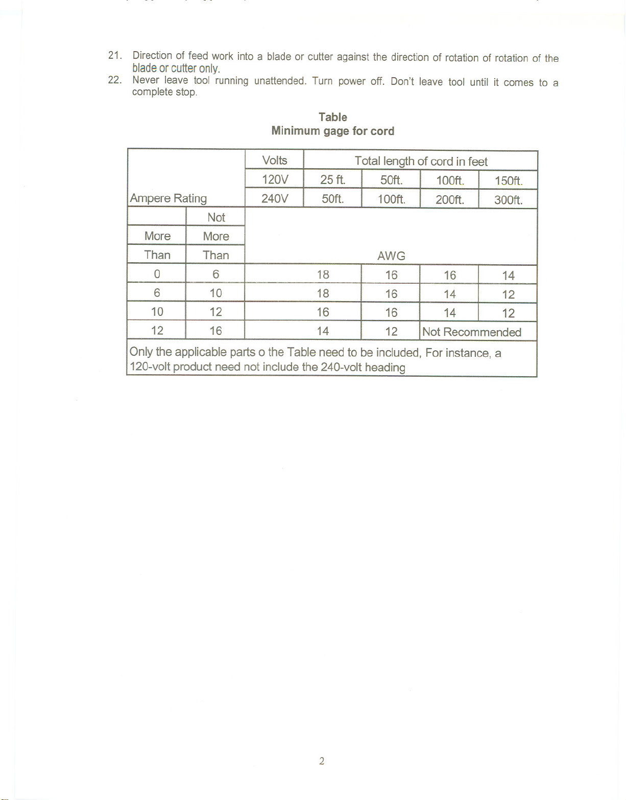
Use proper extension cord. Made sure yourextension cord is ingood condition.When using an
extension cords, be sure to use one heavy enough to carry the current your productwill draw.
An undersized cord will cause a drop in voltage resulting in loss of power and overheating.
Table shows the correct size to use depending on cord length and nameplateampere rating. If
in double, usethe next heaviergage. The smaller the gage number, the heavierthe cord.
10.
Wear proper apparel do not wear loose clothing, gloves, neckties, rings, bracelets, or other
jewelry which may get caught in moving parts. Nonslip footwear is recommended. Wear
protective hair covering to contain long hair.
11.
Always use safety glasses. Also use face or dust mask if cutting operation is dusty. Everyday
eyeglassesonly have impact resistant lenses,they are NOT safety glasses.
12.
Secure work. Use clamp or a vise to hold work when practical. It is safer than usingyour hand
and it frees both hands to operate tool.
13.
Don't overreach. Keep properfooting and balanceat alltimes.
14.
Maintain tools with care. Keep tools sharp and clean for best and safest performance. Follow
instructionsfor lubricatingand changing accessories.
15.
Disconnect tools before servicing; when changing accessories, such as blades, bits, cutters
and the like.
16.
Reducethe riseof unintentionalstarting. Make sure switch is inoff positionbeforeplugging in.
17.
Use recommended accessories. Consult the owner's manual for recommended accessories.
The useof improperaccessories may cause risk of injuryto person.
18.
Some dust created by power sanding, sawing, grinding, drilling and other construction activities
contains chemicals known to cause cancer, birth defects or other reproductive harm. Some
examples of thesechemicals are:
Wear eye protection.
Do not remove jammed cut off pieces until blade has stopped.
Maintain proper adjustment of blade tension, blade guides, and trust bearing.
Adjust upper guide to just clear workpiece.
Hold workpiece firmly against table.
. Lead from lead based paint
. crystalline silica from bricks and cement and other masonry products, and
. arsenic and chromium from chemically-treatedlumber.
19.
Never stand on tool serious injury could occur if the tool is tipped or if the cutting tool is
unintentionallycontacted.
20.
Check damaged parts. Before further use the tool, a guard or other part that is damaged
should be carefully checked to determine that it will operate properlyand perform its intended
function - check for alignment of moving parts, binding of moving parts, breakage of parts,
mounting, and any other conditions that may affect its operation. A guard or other part that is
damagedshouldbeproperlyrep~iredorreplaced.
1
Page 4
21. Direction of feed work into a blade or cutter against the direction of rotation of rotation of the
bladeor cutter only.
22. Never leave tool running unattended. Turn power off. Don't leave tool until it comes to a
complete stop.
Table
Minimum gage for cord
AmpereRating
Volts
120V
240V
25ft. 50ft.
50ft.
Totallengthof cordin feet
100ft. 150ft.
100ft.
200ft. 300ft.
Not
More More
Than Than
0
6 18
6 10
10 12
12
16 14 12
18
16
AWG
16
16
16
16
14 12
14 12
NotRecommended
Onlytheapplicableparts0 theTableneedto be included,Forinstance,a
120-voltproductneednotincludethe240-voltheading
14
2
Page 5
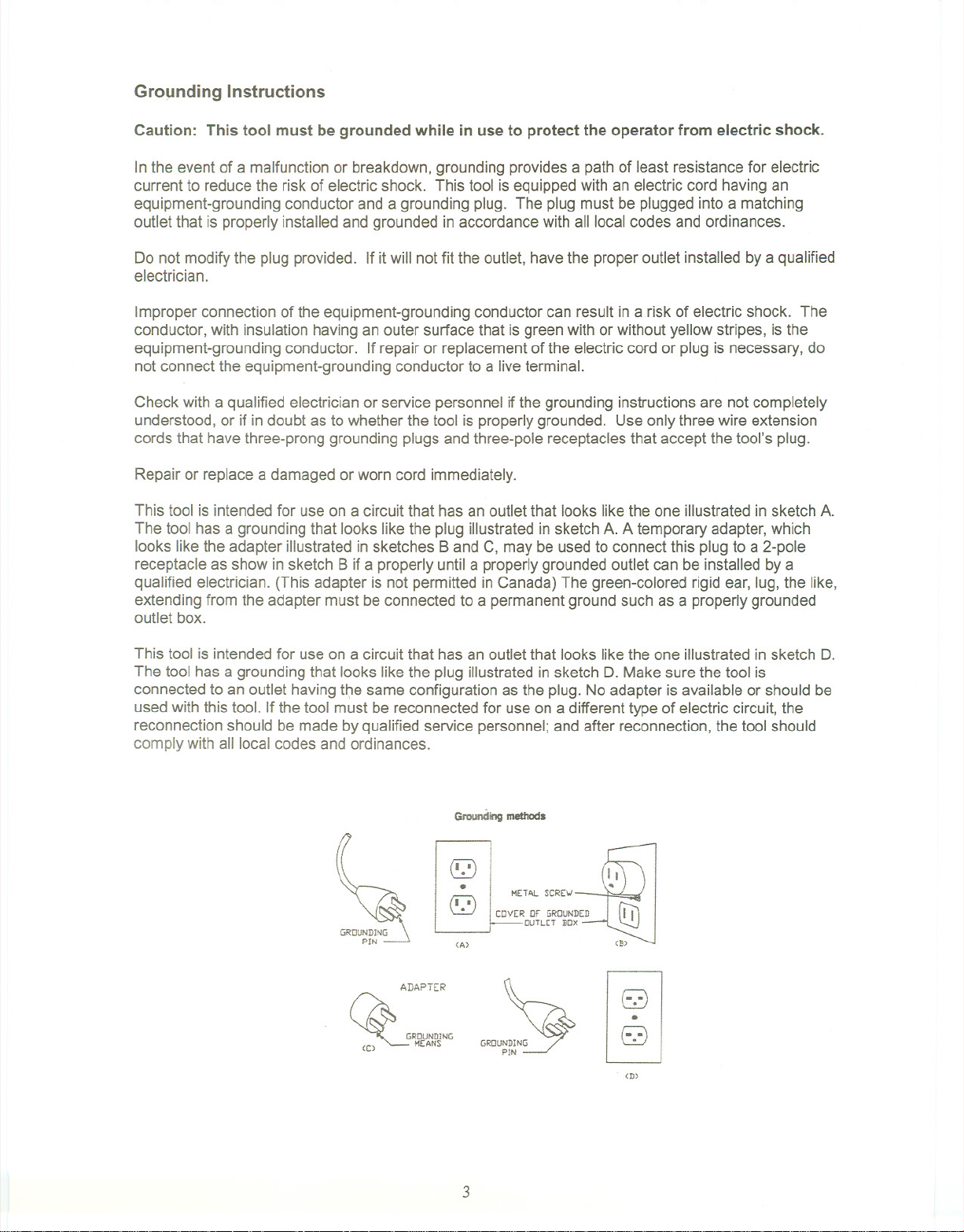
Gro~nding Instructions
Caution: This tool must be grounded while in use to protect the operator from electric shock.
In the eventof a malfunctionor breakdown,grounding provides a path of leastresistancefor electric
current to reduce the risk of electric shock. This tool is equippedwith an electric cord having an
equipment-groundingconductor anda grounding plug. The plugmust beplugged into a matching
outlet that is properly installed and grounded in accordancewith all localcodesand ordinances.
Do not modifythe plug provided. If itwill notfit the outlet,have the properoutlet installed bya qualified
electrician.
Improperconnection of the equipment-groundingconductor can resultin a risk of electric shock. The
conductor, with insulationhavingan outersurface that isgreen with or without yellow stripes, is the
equipment-groundingconductor. If repair or replacement of the electric cord or plug is necessary, do
not connectthe equipment-groundingconductorto a live terminal.
Check with a qualified electricianor service personnelif the grounding instructionsare not completely
understood,or if indoubt asto whether the tool is properlygrounded. Useonlythree wire extension
cords that have three-prong grounding plugsandthree-pole receptaclesthat accept the tool's plug.
Repairor replacea damaged or worn cord immediately.
This tool is intended for use on a circuit that has an outlet that looks like the one illustrated in sketch A.
The tool has a grounding that looks like the plug illustrated in sketch A. A temporary adapter, which
looks like the adapter illustrated in sketches Band C, may be used to connect this plug to a 2-pole
receptacle as show in sketch B if a properly until a properly grounded outlet can be installed by a
qualified electrician. (This adapter is not permitted in Canada) The green-colored rigid ear, lug, the like,
extending from the adapter must be connected to a permanent ground such as a properly grounded
outlet box.
This tool is intended for use on a circuit that has an outlet that looks like the one illustrated in sketch D.
The tool has a grounding that looks like the plug illustrated in sketch D. Make sure the tool is
connected to an outlet having tf;le same configuration as the plug. No adapter is available or should be
used with this tool. If the tool must be reconnected for use on a different type of electric circuit, the
reconnection should be made by qualified service personnel; and after reconnection, the tool should
comply with all local codes and ordinances.
Grounding methods
(Q)
~
GROUNDINQ
PIN
.
(Q)
(A)
ADAPTER
METAL SCRE\.!
COVER or GROUNDED
OUTLET BOX
~
~ GROUNDING
~ M(ANS
'''~~
~p~N~
~
<D)
3
Page 6
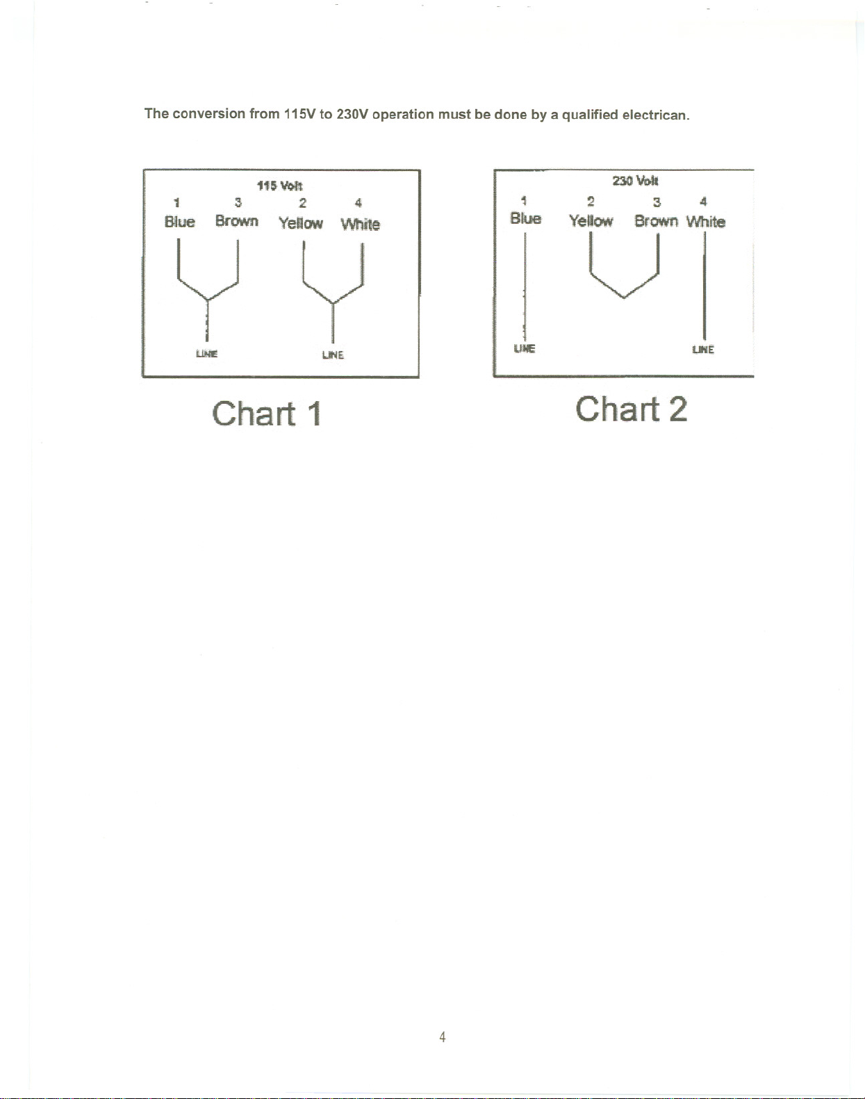
The conversion from 115Vto 230Voperation must be done by a qualified electrican.
1
B1ue
1t5VOft
3 2 4
Bn1wn YeliCIN White
UNI!
~E
Chart 1
1
Blue:
UJE
230Vote
234
Yellow 8rownWbite
U
UtE:
Chart 2
4
Page 7
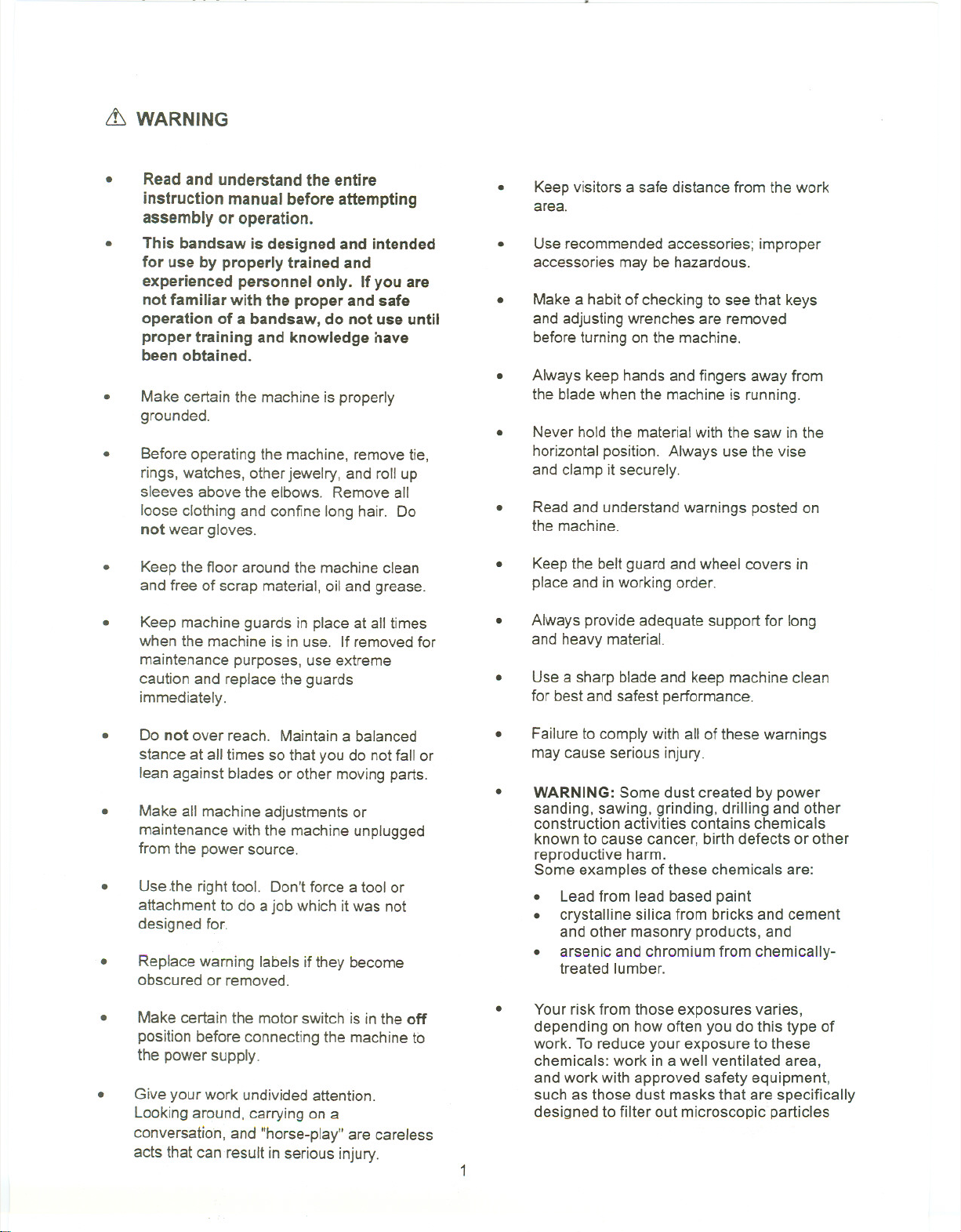
it WARNING
.
Read and understand the entire
instruction manual before attempting
assembly or operation.
.
This bandsaw is designed and intended
for use by properly trained and
experienced personnel only. If you are
not familiar with the proper and safe
operation of a bandsaw, do not use until
proper training and knowledge nave
been obtained.
.
Make certain the machine is properly
grounded.
.
Before operating the machine, removetie,
rings, watches, otherjewelry, and roll up
sleeves abovethe elbows. Remove all
loose clothing and confine long hair. Do
not wear gloves.
.
Keepvisitors a safe distance from the work
area.
.
Use recommendedaccessories; improper
accessories may be hazardous.
.
Makea habitof checking to see that keys
and adjustingwrenches are removed
beforeturning onthe machine.
.
Always keep hands and fingers away from
the bladewhen the machine is running.
.
Never hold the materialwith the saw in the
horizontalposition. Always use the vise
and clamp it securely.
.
Readand understandwarnings posted on
the machine.
.
Keepthe floor around the machineclean
and free of scrap material, oil and grease.
.
Keep machine guards in placeat all times
when the machine is in use. If removedfor
maintenance purposes, use extreme
caution and replace the guards
immediately.
.
Do not over reach. Maintaina balanced
stance at all times sothat you do notfall or
lean against bladesor other movingparts.
.
Make all machine adjustmentsor
maintenance with the machine unplugged
from the power source.
.
Use.the right tool. Don't force a tool or
attachment to do a job which it was not
designed for.
.
Replace warning labels ifthey become
obscured or removed.
.
Make certain the motor switch is in the off
position before connecting the machineto
the power supply.
.
Give your work undivided attention.
Lookingaround, carrying on a
conversation,and "horse-play" are careless
acts that can resultin seriousinjury.
.
Keepthe belt guard and wheel covers in
placeand in working order.
.
Always provideadequate support for long
and heavy material.
.
Usea sharp bladeand keepmachine clean
for best and safest performance.
.
Failureto comply with all of these warnings
may cause serious injury.
.
WARNING: Some dust created by power
sanding, sawing, grinding, drilling and other
construction activities contains chemicals
known to cause cancer, birth defects or other
reproductive harm.
Some examples of these chemicals are:
. Leadfrom lead based paint
. crystalline silica from bricks and cement
and other masonry products, and
. arsenic and chromium from chemically-
treated lumber.
.
Your risk from those exposures varies,
depending on how often you do this type of
work. To reduce your exposure to these
chemicals: work in a well ventilated area,
and work with approved safety equipment,
such as those dust masks that are specifically
designed to filter out microscopic particles
Page 8
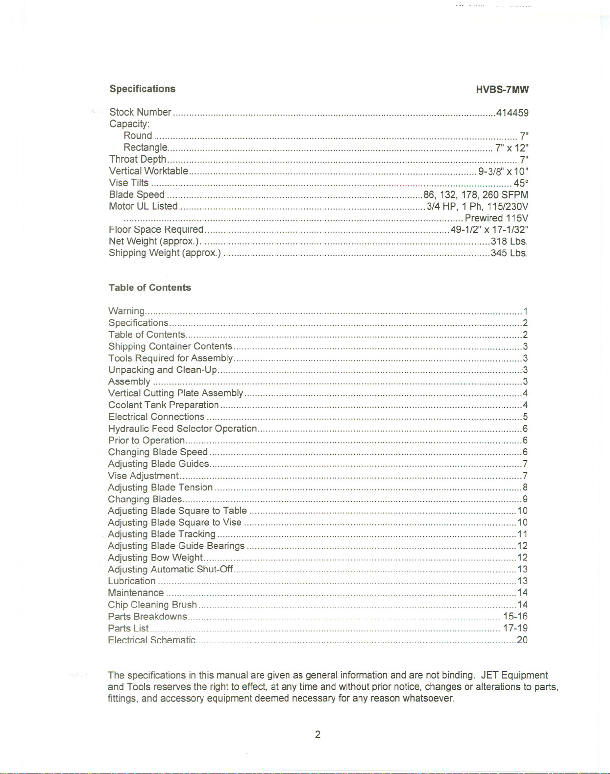
Specifications
Stock Number 414459
Capacity:
Round 7"
Rectangle 7" X12"
Throat Depth '.'"'''''''''''''''''''''''''' 7"
Vertical Worktable 9-3/8"x 10"
Vise Tilts 45°
Blade Speed 86, 132,178,260 SFPM
Motor UL Listed 3/4 HP, 1 Ph, 115/230V
Floor Space Required 49-1/2" x 17-1/32"
NetWeight (approx.) 318 Lbs.
ShippingWeight (approx.) 345 Lbs.
Table of Contents
Warning 1
Specifications 2
Table of Contents 2
Shipping Container Contents 3
Tools Requiredfor Assembly 3
Unpacking and Clean-Up ... ... ... ............... """""""""'" ..3
Assembly ... ... ... ............... 3
Vertical Cutting PlateAssembly 4
Coolant Tank Preparation 4
Electrical Connections ...5
Hydraulic Feed Selector Operation 6
Priorto Operation ...6
Changing.Blade Speed 6
Adjusting BladeGuides.. ...... ... ...... ... ... ... ... 7
Vise Adjustment 7
Adjusting Blade Tension 8
Changing Blades 9
Adjusting Blade Square to Table 10
Adjusting Blade Square to Vise ..." 10
Adjusting Blade Tracking... 11
HVBS-7MW
Prewired 115V
AdjustingBladeGuideBearings , 12
Adjusting Bow Weight 12
Adjusting Automatic Shut-Off 13
Lubrication 13
Maintenance .14
Chip Cleaning Brush 14
Parts Breakdowns 15-16
Parts List .. .. 17-19
Electrical Schematic .20
The specifications inthis manualare given asgeneral informationandare not binding. JET Equipment
and Tools reserves the right to effect, at anytime and without priornotice, changes or alterations to parts,
fittings, and accessory equipmentdeemed necessaryfor any reasonwhatsoever.
2
Page 9
Shipping Container Contents
1 Saw
2 Wheel Axle
4 Wheel
4 SplitPin
1 Material Stop Bar
1 Material Stop
1 Belt Cover
1 Vertical Cutting Plate
Tools Required for Assembly
#2 Cross Point Screwdriver
Pliers
Unpacking and Clean-Up
1. Finish uncrating the saw. Inspectit for shipping
damage. If any damage has occurred, contact
your distributor.
2. Unbolt the saw from the skid and placeit on a
level surface.
3. Clean rust protected surfaces with kerosene,
diesel oil, or a mildsolvent. Do not use cellulose
based solvents such as paintthinner or lacquer
thinner. These will damage paintedsurfaces.
Assembly
1. Place blocking under the ends ofthe saw base
to allowwheel installation. Caution: Makesure
saw is steady while temporarily supported.
2. Slide wheel axles through the holesin the base.
3. Slide the wheels onto the axles andfasten with
pins. Bend the pins to hold in place.
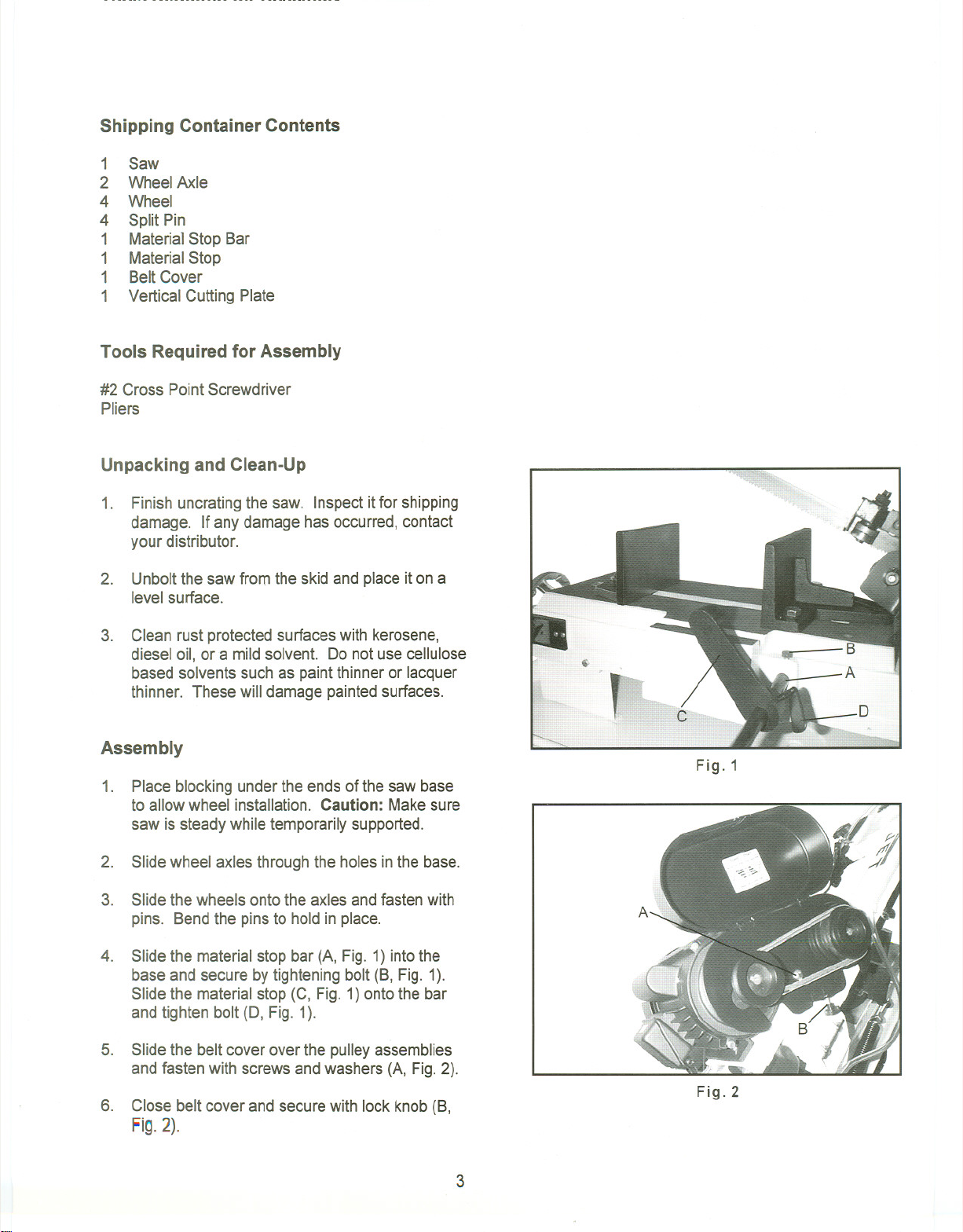
4. Slide the materialstop bar (A, Fig. 1) into the
base and secure by tightening bolt (B, Fig. 1).
Slide the material stop (C, Fig. 1)onto the bar
and tighten bolt (D, Fig. 1).
5. Slide the belt cover over the pulley assemblies
and fasten with screws andwashers (A, Fig. 2).
6. Close beltcover and secure with lock knob (8,
Fig. 2).
Fig.1
Fig.2
3
Page 10

7. Remove transportation strap and keep for later
use should the saw be movedany distance.
,.;.
"-
",---.
-~
Vertical Cutting Plate Assembly
Note: These steps are only necessary if using the
bandsaw inthe vertical mode.
1. Disconnect the bandsaw from the power
source.
2.
Raise the arm to the vertical position by turning
the arm stop (A, Fig, 2A) a quarter turn
clockwise, slowing bringthe arm to vertical,and
lock in place by turning the hydrauliccylinder
valve to the off position. Caution: Do not pinch
fingers between the arm stop and the arm
bracket.
3. Removetwo screws (A, Fig. 3) and remove the
deflector plate (8, Fig. 3).
4. Guide the bladethrough the slot inthe table and
fasten with two screws. See Fig. 4.
\
I
A
Fig.2A
A
5. To lower the arm, turn the hydraulic cylinder arm
to any of the on positions.
Coolant Tank Preparation
Use of a water-soluble coolant will increase cutting
efficiency and prolong blade life. Do not useblack
cutting oil as a substitute. Change cutting oil often
and follow manufacturers instructions as to its uses
and precautions.
1. Disconnect the machine from the power
source.
2. Remove the coolant return hose from thetank
cover.
3.
Slide the tank out of the saw base and carefully
remove the lid containing the coolant pump.
4.
Fillthe tank to approximately80% of capacity.
5.
Place the lid back onto the tank and placethe
tank assembly back intothe base.
6.
Replace the return hose back into the hole in the
tank lid.
Fig.3
Fig.4
4
Page 11

Electrical Connections
The HVBS-7MW bandsaw is rated at 115/230Vand
comes from the factory prewired at 115V. Toswitch
to 230V operation, followthe wiring diagramfound
on the insideof the motorjunction box. Theplug
end will haveto replacedwith a plugthat is ratedat
230V. The coolant pump wiring will haveto be
changed also. Follow the diagramfound on the
cooling pump head to switch to 230Voperation.
This bandsaw is designed for use on a circuitwith an
outlet that looks like (A) inFigure 5. The bandsaw
has a grounding prongas illustratedin (B). A
temporary adapter (C) may be used to connect the
plug to a two pole receptacle(0) if a properly
grounded outlet is not available. The temporary
adapter should only be used until a properly
grounded outlet can be installed by a qualified
electrician. The green colored lug must be securely
fastened to the cover plate screw.
Before hooking up to the powersource, besurethe
power and coolant switches are inthe off position.
CURRENT CARRYING PRONGS
,~
A/
GROUND PRONG
I
Fig. 5
w
e
~
Hydraulic Feed Selector Operation
The hydraulic feed selectoris usedto control the
bladefeed rate and to lockthe arm inthe vertical
position. To increase the feed rate, turn knob (A,
Fig.6) counter-clockwise. To decreasethe feed
rate, turn knob (A, Fig.6) clockwise. To turn off the
flow of hydraulic fluid, turn lever as infigure 6. To
turn the hydraulic cylinder on, raise lever (B, Fig.6)
to the 12o'clock position.
For a detailed discussion of properfeed rate and
cutting speed, referto the enclosed booklet "Lenox
Guide to Bandsawing"published byAmerican Saw
Manufacturing Company. Used by permission.
Fig.6
5
Page 12

Prior to Operation
1. Check to see that the blade tooth direction
matchesthe diagramon saw body.
2. Check to see that the bladeis properlyseated
on the wheels after propertension has been
applied.
3. Set the bladeguide rollerbearingssnug against
blade. See "Adjusting BladeGuideBearings"for
more detail.
4. Check for a slight clearancebetweenthe back
up rollers and the backof the blade.
5. Position both blade guides as close to work as
possible.
6. Select proper speed andfeed ratefor material
being cut. See the enclosed "Lenox Guide to
Bandsawing"for further information.
7. Material to be cut must be held securely in vise.
8. Check to see that coolant levelis adequate.
9.
Do not start a cut on a sharp edge.
1O. Keep the machine lubricated. See the
"Lubrication" section.
Changing Blade Speed
1. Disconnect the machinefrom the power
source.
2.
Loosen the motor plate lock bolt (A, Fig. 7).
3. Loosen motor plateslide bolt (B, Fig. 7) until the
belt can be moved on the the pulleys.
4. Move the belt to the the desired pulley
combination.
5. Tighten the motor plate slide bolt (B, Fig.7) to
re-tension belt.
6. Tighten the motor plate lock bolt (A).
Fig.7
7. Connectthe machineto the power source.
6
Page 13

Adjusting the Blade Guides
1. Disconnect the machinefrom the power
source.
2. Loosen knob (A, Fig.8) and bolt (B, Fig. 8).
Slide te blade guide assemblies as close as
possible to the the materialwithout interfering
with the cut.
3. Tighten knob (A, Fig. 8) and bolt (B, Fig. 8) and
connect machineto the powersource.
Vise Adj ustment
.!..) WARNING
To set the vise for 0 to 45 degree cutting:
1.
Remove the bolt and nut assemblies (C, Fig.9).
2.
Positionthe vise and re-installas picturedin Fig.
10. Pay particular attention to the bolt hole
location.
3. Set the vise to desired angle, re-install nutsand
bolts, and tighten the nut and bolt assemblies.
4. Adjust the movable vise parallelto the fixed vise
by loosening bolt(A, Fig.10),adjusting to
parallel, and tightening bolt.
To set vise for maximumwidth of stock cutting:
1. Remove the nutand boltassemblies.
Fig.8
"-
Fig.9
2. Position the vise and re-installthe bolt
assemblies as pictured in Fig 9.
Fig.10
7
Page 14
Adjusting Blade Tension
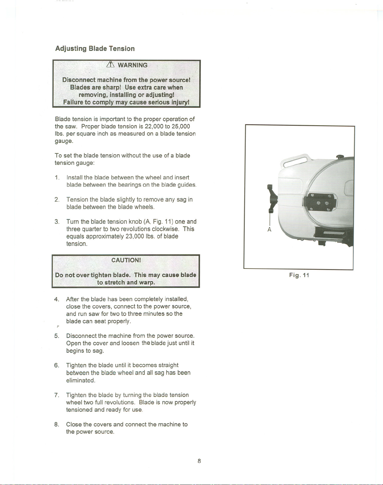
Bladetension is importantto the properoperationof
the saw. Proper bladetension is 22,000 to 25,000
Ibs. per square inch as measuredon a blade tension
gauge.
To set the bladetension without the useof a blade
tension gauge:
1. Installthe blade betweenthe wheel and insert
blade betweenthe bearingson the blade guides.
2. Tension the blade slightlyto removeany sag in
blade betweenthe bladewheels.
3. Turn the blade tension knob (A, Fig. 11)one and
three quarter totwo revolutionsclockwise. This
equals approximately 23,000 Ibs.of blade
tension.
r
A
CAUTIONI
4. After the blade has been completelyinstalled,
close the covers. connect to the power source,
and run saw for two to three minutesso the
blade can seat properly.
r
5. Disconnectthe machinefrom the power source.
Open the cover and loosen the bladejust until it
begins to sag.
6. Tighten the blade until it becomesstraight
betweenthe bladewheel and all sag hasbeen
eliminated.
7. Tighten the blade byturning the bladetension
wheel two full revolutions. Bladeis now properly
tensioned and ready for use.
8. Close the covers and connectthe machineto
the power source.
Fig.11
8
Page 15

Changing Blades
1. Disconnect the machinefrom the power
source.
2. Raise the saw arm to the vertical positionand
lock in place by turning the hydrauliccylinder off.
3.
Remove the red blade guard assembly (A, Fig.
12) by removing two screws (B, Fig.12).
4.
Remove the brush assembly (C, Fig. 12) by
removing two screws (0, Fig. 12).
5. Loosen blade tension byturning the blade
tension knob counter-clockwise.
6. Carefully remove the old blade. Caution:
blade teeth are sharp. Handlewith care.
7. Install the new blade by placing the blade
between blade guides first. Makesure the blade
teeth face the same direction as indicatedon the
label found on the saw arm.
8. Placethe bladearound bothwheels. Make sure
the blade edge rests nearthewheel flange on
both wheels.
Fig.12
9
Page 16

9. Turn the blade tension knob clockwise to tension
the blade. Do not over tension. See section
titled "Adjusting Blade Tension",
10. Close the bladecover door and securewith lock
knobs.
11. Attach the redblade guard and brush assembly.
12. Connect the machine to the power source.
13. Runthe saw and make sure blade istracking
properly.
For a discussion on blade selection, see the
enclosed booklet entitled "Lenox Guide to
Bandsawing".
Adjusting Blade Square to Table
1. Disconnect machinefromthe powersource.
2. Place a machinist'ssquare on the table next to
the blade as pictured in Fig. 13.
3, Check to see that the blade makescontactwith
square along the entirewidth ofthe blade.
4. If adjustment isnecessary, loosen bolts (A, Fig.
13) and rotate the blade guide assemblies
slightly in the same direction untilthe blade
makes contact with the squarealong it's entire
width.
5. Tighten bolts (A, Fig. 13).
6. Connectthe machineto the powersource.
Note: If adjustment to square blade to table is
necessary, be sure to check blade adjustments
again.
----
Fig.13
Adjusting Blade Square to Vise
1. Disconnect the machine from the power
source.
2. Place a machinist'ssquare as picturedin Figure
14. Square shouldlie along the entire length of
vise and bladewithout a gap.
Fig.14
10
Page 17

3. Ifadjustment is necessary, loosenthe bolts
holding the vice and adjustthe vise so that the
square lines up properly.Tighten bolts.
4. Connect machine to the power source.
Adjusting Blade Tracking
Note: Before making any tracking adjustments, try a
new blade. Warped blades will not track.
Blade tracking has been set at the factory and
should not require adjustment. If a tracking
problems occurs, adjust the machine as follows:
1. Move the saw arm to the vertical positionand
lock in place by shuttingoff the hydraulic
cylinder valve.
2. Confirm that blade tension is set properly. To
adjust, see section titled "AdjustingBlade
Tension".
3. Open the back cover by looseningthe lock
screws.
4. Run the saw and observe the blade. Blade
should runnext to but not tightly against wheel
flange.
5.
Loosen bolts (A, Fig. 15).
6. Turn set screw (B, Fig. 15)while observing the
blade tracking on the wheel. Turn the set screw
clockwise to track the blade closer to the wheel
flange. Turn the set screw counter-clockwiseto
track blade away from the wheel flange.
7. Once tracking is set, tighten bolts(A, Fig. 15).
B
Fig.15
11
Page 18

Adjusting Blade Guide Bearings
1. Disconnect the machine from the power
source.
2. Raise the arm to theverticalpositionand lockin
place byturningoffthe the hydrauliccylinder
valve.
3. Loosen the hex cap screw (A,Fig. 16) and
adjust assembly so that the back rollerbearing
is approximately.003"- .005"fromthe back of
the blade.
4. Turn nut (B, Fig. 16) to adjust the eccentric
bearing snug to the blade. Blade should still
move up and down freely when grasped as in
Fig. 17. Warning! Make sure power is
disconnected and hands are protected
before handling blade. ~e sure that the blade
teeth do not interferewith the roller bearings.
5. Repeatfor the other blade guide assembly.
B
Fig.16
6. Connect machine to the power source.
Adjusting Bow Weight
Bowweightis one ofthe most importantadjustments
of the saw. Ifthe bow weight is not set properly,one
can expect poor performance,crooked cuts, tooth
stripping, stalling, and the blade poppingoff the
bladewheels. The hydraulicfeed rate unitwill not
compensate for improper bow weight. Bowweight
has been set at the factory and shouldnot need
adjustment. If adjustment is necessary:
1. Disconnect the machine from the power
source.
2. Turn the hydraulic cylinder valve on and place
the the saw arm in horizontal position.
3. Turn feed ratevalve on hydrauliccylinder
counter-clockwise untilit stops.
Fig.17
12
Page 19

4. Place a fish-type scale under the bladetension
handle and liftthe saw arm. Scale should
indicate approximately 13-15 Ibs.
5. Adjust tension to approximately 13-15 Ibs.by
turning bolt (At Fig. 18).
6. Connect the machineto the power source.
Adjusting Automatic Shutoff
The saw should stop afterthe cut has been
completed:
1. If the saw completes the cut and continuesto
run, adjust the stop tip (A, Fig. 19) down.
2. Ifthe saw shuts off before the cut is complete,
adjust the stop tip (A, Fig. 19) up.
3. Ifthe saw stops cutting but continuesto run,
adjust the stop bolt (B, Fig. 19).
The saw is properlyadjusted when thesaw shuts off
just after the blade has finished the cut.
Fig.18
}/
Lubrication
Ball bearings on the blade guide assembliesand the
bladewheels are permanentlysealed and require no
lubrication.
Lightly lubricate the vise screw with #2 tube grease.
Change gear box oil after the first 90 days of
operation. There after, changeevery six months
To change gear box oil:
1. Disconnect the machine from the power
source.
2. Place the saw arm in the horizontalposition.
3. Remove screws (A, Fig. 20) from the gear box
and remove the cover plateand gasket.
4. Hold a container under the lower right corner of
the gear box with one handwhile slowly raising
the saw arm with the other.
I
.
A
Fig.19
Fig.20
13
Page 20

5. Placethe saw arm in the horizontalposition
again. Wipe out remaining oil witha rag.
6. Fillthe gear box with approximately3/4 pint of
90 weight gear oil.
7. Replace the gasket and cover. Fastenthe cover
with screws.
8. Connect machinetTthe power~ource.
Maintenance
1. Keep all surfaces cleanand free of rust, slag,
chips, and coolant build-up.
2. Do not use compressed air to clean the
bandsaw. Compressedair mayforce chips into
the guide bearings and other critical areas of the
saw.
3; Use a small paint brush or parts cleaning brush
to remove metal particles.
4. Wipe the saw downwith a clean, drycloth and
oil all unpainted surfaces with light machineoil.
5. Keepthe blade guides clean and free of metal
chips.
6. Checkthe guide bearingsfrequently to make
sure they are properly adjusted and turning
freely.
Chip Cleaning Brush
It is very important that the bladecleaning brush be
properly adjusted and kept in good working order.
Replace the brush if it becomes damaged or worn
out. Blade life will be shortened severely ifthe brush
is allowed to go out of adjustment, becomes
damaged, or is worn out.
14
Page 21

:::
153
\52
i
5\ . 15\
157
156
66
.......
(J"I
~2 436
-~/'~
,~
!~(~~5~
?3(~)
22(~)
I~
Page 22

...
.............
...
.............
...
~~
82
11
.............
...
.............
'97(2)
...
.............
110(2) ...
127
(()
73
...~
93(2)
-150(4)
~W 64
71
Page 23

Parts List For The HVBS-7MW Bandsaw
Index Part
No. No.
Description
Size
Qty.
1 HVBS7MW-1 Coolant Pan , 1
2 HVBS7MW-2 Base Leg (left) 1
3 HVBS7MW-3 Base Leg (right) 1
4 HVBS7MW-4 Skirt 1
5 HVBS7MW-5 Shelf 1
6 HVBS7MW-6 Toggle Switch 1
7 HVBS7MW-7 ElectricalBox 1
8 TS-0051 031 Hex Cap Bolt 5/16x3/4 '''''''''''''''''' 10
9 TS-0720081 Lock Washer 5/16 32
10 TS-0680031 Flat Washer 5/16 18
11 TS-0561 021 Hex NuL 5/16 27
12 TS-0051 011 Hex Cap Bolt "'''''''''''''''''''''''''''''''''''''''''''''''''' 5/16x1/2 8
13 HVBS7MW-13 """""'"'''''' Cylinder Assembly (SIN: 010218160 and lower) 1
HVBS7MW-13-RK Cylinder Repair Kit (not shown) 1
14 TS-150506 Hex Socket Cap Screw M1Ox40 1
15 TS-0680041 Flat Washer '''''''''''''''''''''''''''''''''''''''''''''''''''' 3/8 6
16 TS-0720091 Lock Washer 3/8 11
17 TS-154007 Hex Nut M10 1
18 TS-0060051 Hex Cap Bolt "" 3/8x1 2
19 HVBS7MW-19 Support Rod 1
20 TS-0050011 Hex Cap Bolt .." 1/4x1/2 1
21 HVBS7MW-21 Bottom Support 1
22 TS-0680081 Flat Washer 5/8 4
23 HVBS7MW-23 Wheel 5" 4
24 HVBS7MW-24 Wheel Shaft 2
25 HVBS7MW-25 Split Pin 4
26 HVBS7MW-26 Power Cord 1
HVBS7MW-26-1 Power Cord (motor - main switch -not shown) 1
HVBS7MW-26-2 Power Cord (main switch - pump - not shown) 1
27 HVBS7MW-27 """""""'"'' Table 1
28 TS-0081051 Hex Cap Bolt 5/16x1 10
29 HVBS7MW-29 Filter Assembly 1
30 HVBS7MW-30 Hex Head Screw 3/16x3/8 2
31 HVBS7MW-31 Switch Box Assembly (SIN: 5011368 & lower) 1
"'''''''''' HVBS7MW-31 N Switch Box Assembly (SIN: 5011369 & higher) 1
HVBS7MW-31A Switch (SIN: 5011368 & lower) 1
HVBS7MW-31AN Switch (SIN: 5011369 & higher) 1
32 HVBS7MW-32 ' " Wheel Handle 1
33 HVBS7MW-33 Key 5x20 1
34 HVBS7MW-34 Lead Screw 1
35 HVBS7MW-35 Nut Seat 1
36 HVBS7MW-36 Strain Relief Assembly 1
37 HVBS7MW-37 """"""""'" Support Plate 1
38 HVBS7MW-38 Stop Screw 1
39 TS-0060061 Hex Cap Bolt .." 3/8x1-1/4 4
40 TS-0561 031 Nut 3/8 8
41 HVBS7MW-41 90° Support 1
42 TS-0060071 Hex Cap Bolt 3/8x1-1/2 4
43 TS-0270031 Set Screw 5/16x3/8 4
44 HVBS7MW
45 HVBS7MW-45 Stop Block 1
-44 Thumb Screw 1
17
Page 24

46 HVBS7MW-46 Stop Rod 1
47 TS-0561 031 Hex Nut 1/2 2
48 TS-0680061 Flat Washer 1/2 4
49 TS-026702 Set Screw 1/4x1/4 2
50 HVBS7MW-50 Support Shaft 1
51 HVBS7MW-51 " Pivot Arm (SIN: 80910746 and lower) 1
HVBS7MW-51 N Pivot Arm (SIN: 80910747 and higher) 1
52 TS-0720091 ... Lock Washer ...... 3/8 "" ......2
53 HVBS7MW -53 Spring 1
54 HVBS7MW-54 Spring Adjusting Rod 1
55 HVBS7MW-55 Spring Bracket 1
56 TS-0051 061 Hex Cap Bolt 5/16x1-1/2 5
57 HVBS7MW-57 Vise Jaw (left) " 1
58 HVBS7MW-58 Vise Jaw (right) 1
59 HVBS7MW-59 Scale (SIN: 010217984 and lower) 1
HVBS7MW-59N ,.. Scale (SIN: 010217985 and higher) 1
60 HVBS7MW-60 Arm Support Plate 1
61 TS-020908 Hex Socket Cap Screw 3/8x1-3/4 1
62 HVBS7MW -62 Hose 1
63 HVBS7MW-63 Pump 1
64 TS-0050021 Hex Cap Bolt * 1/4x5/8 6
65 HVBS7MW-65 Tank Cover (SIN: 8091100 and lower) 1
66 HVBS7MW-66 Coolant Tank (SIN: 8091100 and lower) 1
HVBS7MW-66N New Coolant Tank (SIN: 80911001 and higher) 1
66-1 HVBS7MW-66-1 N Plastic Funnel (SIN:
67 HVBS7MW-67 Hose Fitting " 1
68 HVBS7MW-68 Hose Clamp 1
69 HVBS7MW -69 Hose " 1
70 HVBS7MW-70 " Saw Bow (SIN: 8091100 and lower) 1
HVBS7MW-70N Saw Bow (SIN: 8091101 and higher) 1
HVBS7MW-70N1 Saw Bow (JET Mark)( SIN: 010218161 and higher) 1
71 HVBS7MW-71 Vent Plug * 1
72 HVBS7MW-72 Gear Box Cover * 1
73 HVBS7MW-73 , Gear Box Gasket * 1
74 HVBS7MW-74 Worm Gear *( SIN: 00114808 and lower) 1
HVBS7MW-74N Worm Gear *( SIN: 00114809 and higher) 1
75 TS-051061 Hex Cap Bolt * 5/16x1-1/4 1
76 BB-6005Z " Ball Bearing * 3
77 HVBS7MW-77 C-Ring * S-25 2
78 HVBS7MW-78 Oil Seal * , 1
79 HVBS7MW-79 Gear Box * 1
80 HVBS7MW-80 " Blade Wheel (right)(S/N: 00114808 and lower) 1
HVBS7MW-80N Blade Wheel (right)(S/N: 00114809 and higher) 1
81 HVBS7MW-81 Worm Bushing * " 1
82 HVBS7MW-82 " Bi-Metal Blade 1
83 HVBS7MW-83 Wheel Cover 1
84 HVBS7MW-84 ." Rear Wheel Cover 1
85 HVBS7MW-85 Plum Screw 2
86 HVBS7MW -86 Lock Knob 2
87 HVBS7MW-87 Adjustable Bracket (right) ,.. 1
88 BB-608ZZ Ball Bearing 2
80911001 and higher) 1
89 HVBS7MW-89 ".. Adjustable Blade Seat(right) " 1
90. HVBS7MW -90 Bearing Pin 2
91 HVBS7MW-91 " Eccentric Shaft Assembly (outside) 2
HVBS7MW-91A Center Shaft Assembly(inside)(S/N: 80910747 and higher) 2
BB-608ZZ... Ball Bearing (not shown) 8
HVBS7MW-91-2 Eccentric Shaft (outside)(not shown) 2
HVBS7MW-91A-2 Center Shaft (inside)( SIN: 80910747 and higher) 2
HVBS7MW-91-3 C-Ring (not shown) 4
18
Page 25

92 TS-0561 031 Hex Nut 3/8 4
93 HVBS-7MW-91-4 Flat HeadScrew 1/4x3/8 2
94 HVBS7MW-94 Vertical Cutting Plate 1
95 HVBS7MW-95 Top Support 1
96 TS-0813032 Round Head Screw 1/4x1/2 6
97 TS-0680021 FlatWasher 1/4 11
98 HVBS7MW-98 Brush Holder 1
99 TS-0060111 Hex Cap Bolt 3/8x2-1/2 2
100 HVBS7MW-100 Brush... "'''''''''''''''''''''''''''''''' 1
101 HVBS7MW -101 Nozzle Cock 1
102 TS-0267021 Set Screw 1/4x1/4 3
103 HVBS7MW-103 Nozzle Cock Support 1
104 HVBS7MW -104 Valve 1
105 TS-0208071 Hex Socket Cap Screw 5/16x1-1/4 2
106 HVBS7MW-1 06 Adjustable Bracket (left) 1
107 HVBS7MW-107 Adjustable Blade Seat (left) 1
108 HVBS7MW-108 Blade Guard 1
109 HVBS7MW-1 09 Brush Support 1
110 TS-0050011 Hex Cap Bolt 1/4x1/2 7
111 HVBS7MW-111 Guide Plate ""'''''''''''''''''''''''''''''''''''''''''''''''''' 2
112 HVBS7MW-112 """'"'''''''' Set Screw 5/16x3/4 1
113 TS-0051 071 Hex Cap Bolt 5/16x1-1/2 2
114 HVBS7MW-114 """""""'" Blade Tension Block 1
115 HVBS7MW-115 Sliding Draw Block 1
116 HVBS7MW-116 Switch Cut-Off Trip 1
117 HVBS7MW-117 Bearing Bushing 1
118 BB-6203Z """"'''''''''''''''''' Ball Bearing 2
119 HVBS7MW-119 Wheel 1
120 HVBS7MW-120 Blade Tension Handwheel 1
121 HVBS7MW-121 Vertical Cutting Plate 1
122 VB-3V270 """'''''''''''''''''''' V-Belt 1
123 HVBS7MW-123 '"'''''''''''''' Worm Pulley 1
124 HVBS7MW-124 """'"'''''''' Motor Pulley 1
125 HVBS7MW-125 Hex Head Screw 1/4x3/8 2
126 HVBS7MW-126 Pulley Cover 1
127 HVBS7MW-127 Lock Screw
128 TS-0720071 Lock Washer 1/4 1
129 HVBS7MW-129 Motor 1
HVBS7MW-129A Motor Fan (not shown) 1
HVBS7MW-129B Motor Fan Cover (not shown) 1
130 HVBS7MW-130 Motor Mount Plate 1
131 HVBS7MW-131 C-Ring * S-17 ""'"'''''''''''''''''''' 1
132 BB-6003Z Ball Bearing * 3
133 HVBS7MW-133 C-Ring * R-35 1
134 HVBS7MW-134 Oil Seal * 1
135 HVBS7MW-135 Bearing Bushing * 1
136 HVBS7MW-136 Worm Shaft * 1
137 HVBS7MW-137 Support Plate 1
138 HVBS7MW-138 Motor Support Plate 1
139 TS-0070031 Hex Cap Bolt 1/2x1-1/2 2
140 TS-0720111 Lock Washer 1/2 2
141 HVBS7MW-141 Key 5x20 1
142 HVBS7MW-142 "'"'''''''''''' Key * 6x20 2
143 HVBS7MW-143 Hose Clamp 2
144 HVBS7MW-144 Bearing Bushing 1
145 HVBS7MW-145 "'"'''''''''''' FlatWasher 3/8 4
146 HVBS7MW-146 Cross Screw 1/8 x 1/4 2
19
1
Page 26

147 HVBS7MW-147 FlatWasher 1/8 2
148 HVBS7MW-148 StrainRelief Bushing 2
149 HVBS7MW-149 Strain Relief 2
150 HVBS7MW-150 E-Ring E-7 2
151 HVBS7MW-151 SupportScrew 1
152 HVBS7MW-152 .Bracket , 1
HVBS7MW-152A Arm StopAssembly CP , 1
153 HVBS7MW-153 Spring 1
154 HVBS7MW-154 SpringCap... ".. 1
155 HVBS7MW-155 Hex Socket Cap Screw 3/16 x 1/2 1
156 TS-0561031 Nut " 3/8 1
157 TS-0710091 LockWasher. 3/8 2
158 TS-0060051 Hex Cap BoiL 3/8x 1 1
HVBS7MW-GB Gear BoxAssembly (notshown) 1
159 HVBS7MW-159 Hex HeadScrew 5/16"x3/4" 1
160 HVBS7MW-13-1 ControlValve For Hyd. Cylinder 1
*
included in HVBS7MW-GB Gear Box Assembly
20
Page 27

Electrical Schematic
r ,
I =- Q I
I 6 I
I I
r-- CONJUNCT BOX
Yellow
Red
Green Green
Whrte- White
Black Black
Main Motor Dual Voltage Wiring
115V
3 2 4
SAW MOTOR
POWER
ON-OFF
SWITCH
White
230V
Blue
Brown
Power Cord Power Cord
Coolant Pump Dual Voltage Wiring
115V
Yellow
White
Power Cord
Blue
21
230V
White
Page 28

 Loading...