

Page 1

This Manual is Bookmarked
Operating Instructions and Parts Manual
Semi-Automatic Bandsaw
Model HBS-1321W
WMH TOOL GROUP
2420 Vantage Drive
Elgin, Illinois 60123 Part No. M-414471
Ph.: 800-274-6848 Revision G 7/05
www.wmhtoolgroup.com Copyright © WMH Tool Group
Page 2

2
Warranty and Service
WMH Tool Gr oup warrants ever y product it sell s. If one of our tools needs s ervice or repai r, one of our
Authorized S ervic e Center located throughout t he United States can provide quick servi c e or information.
In most cases, a W MH Tool Group Servi ce Center can assist i n authori zing repai r work, obtai ning part s,
or perform routine or major maintenance repai r on your JET produc t.
For the name of an Aut horized Service Cent er in your area, pl ease call 1-800-274-6848, or vi sit our web
site at www.wmhtoolgroup.com
More Information
Remember, WMH Tool Group i s consistently adding new products to the li ne. For complete, up-to-dat e
product information, check with your local WMH Tool Group distributor, or visit our web site at
www.wmhtoolgroup.com
WMH Tool Group Warranty
WMH Tool Group makes every effort to assure that it s products meet high quality and durability standards
and warrants to the original retail consumer/purchaser of our products that each product be free from
defects in mat erials and workmanship as foll ows: 1 YEAR LI MITED WARRANTY ON ALL PRODUCTS
UNLESS SPECIFIED OTHERWISE. This Warranty does not apply to defects due directly or i ndirectly to
misuse, abuse, negl igence or acc idents, norm al wear-and-tear , repair or alterati ons outside our f aciliti es,
or to a lack of maintenanc e.
WMH TOOL GROUP LIMITS ALL IMPLIED WARRANTIES TO THE PERIOD SPECIFIED ABOVE,
BEGINNING FROM THE DATE THE PRODUCT WAS PURCHASED AT RETAIL. EXCEPT AS STATED
HEREIN, ANY IMPLIED WARRANTIES OR MERCHANTABILITY AND FITNESS ARE EXCLUDED.
SOME STATES DO NOT ALLOW LIMITATIONS ON HOW LONG THE IMPLIED WARRANTY LASTS,
SO THE ABOVE LIMITATION MAY NOT APPLY TO YOU. IN NO EVENT SHALL WMH TOOL GROUP
BE LIABLE FOR DEATH, INJURIES TO PERSONS OR PROPERTY, OR FOR INCIDENTAL,
CONTINGENT, SPECIAL, OR CONSEQUENTIAL DAMAGES ARISING FROM THE USE OF OUR
PRODUCTS. SOME STATES DO NOT ALLOW THE EXCLUSION OR LIMITATION OF INCIDENTAL
OR CONSEQUENTIAL DAMAGES, SO THE ABOVE LIMITATION OR EXCLUSION MAY NOT APPLY
TO YOU.
To take advantage of this warranty, the product or part must be returned for examination, postage
prepaid, to an Authorized Service Center designated by our office. Proof of purchase date and an
explanati on of the complaint m ust accompany the merchandi se. If our inspecti on discloses a defec t, we
will either repair or replace the produc t at our discret ion, or r efund t he purchase pri ce if we cannot readi l y
and quickly provide a repai r or replac ement. We will return the repai red product or replacem ent at WMH
Tool Group’s ex pense, but if it is determ ined there i s no defect, or that the def ect resulted f rom causes
not within the scope of WMH Tool Group’s warranty, then the user must bear the cost of storing and
returning t he product . This warranty gives you specif ic legal ri ghts; you m ay also hav e other ri ghts, which
vary from state t o state.
WMH Tool Group sells through distributor s only. Members of the WMH Tool Group reserve the right to
effect at any time, wit hout prior notice, alter ations to parts, fittings and accessory equi pment, which they
may deem necessary for any reason whatsoever.
Page 3

WARNING
• Read and understand th e entire instruction manual befo re at t emptin g assemb ly or operation.
• All JET bandsaws are design ed and in t end ed for use by properly trained and experienced
personnel only. If you are not familiar with the proper and safe operation of a bandsaw, do
not use until proper t rain ing and knowledge have been obtained.
• Always wear approved safety glasses/fac e shi elds while using this machine.
• Make certain t he machine is properly grounded.
• Before operating the machine, remove tie, rings, watches, other jewelr y , and roll up sleeves above
the elbows. Remove all loose clothing and confine long hai r. Do NOT wear gloves.
• Keep the floor around the machine clean and free of scrap material, oil and grease.
• Keep machine guards i n plac e at all times when the machine is in use. If removed for maint enance
purposes, use extreme caution and replace the guards immediately.
• Do NOT over reach. Maintain a balanc ed stanc e at all times so that you do not fall or lean against
blades or other moving parts.
• Make all machine adjustments or maintenance with t he machine unplugged from the power source.
• Use the right tool . Don't f or c e a tool or att ac hm ent to do a job which it was not designed for.
• Replace warning l abels if they become obscured or removed.
• Make certain t he motor switc h is in the OFF position before connecting the machine to the power
supply.
• Give your work undiv ided attention. Looking around, carrying on a conversation, and " hor se-play"
are careless acts that c an r esul t in serious injury.
• Keep visit or s a safe di stanc e from the work area.
• Use recommended accessories; improper accessories may be hazardous.
• Make a habit of checking to see that keys and adjusting wrenches are rem ov ed before turning on the
machine.
• Always keep hands and finger s away from the blade when the machine i s running.
• Never hand hold the mater ial. Always use the vise and clamp it securely.
• Keep belt guard, blade guards, and wheel covers in pl ace and i n working order.
• Always provi de adequate support for long and heavy material.
• Use a sharp blade and keep machine clean for best and safest performance.
• Failure to comply with all of these warnings may cause serious injury.
Page 4

4
Specifications:
Model: HBS-1321W
Stock Number....................................................................................................................414471
Capacity:
Round at 90° (in) ................................................................................................................. 13
Round at 45° (in) ................................................................................................................. 13
Rectangle at 90° (in)...............................................................................................13 x 16-1/2
....................................................................................................................................... 7 x 21
Rectangle at 45° (in)...............................................................................................13 x 15-1/2
Throat Depth (in)....................................................................................................................... 13
Blade Size (in) ...........................................................................................1-1/4 ” x .042 x 161-1/2
Blade Wheel Diameter (in)........................................................................................................ 18
Blade Speeds (SFP M) ........................................................................................................66-264
Floor Space Requi r ed (i n)............................................................................................84 x 32-1/2
Bed Height (in).......................................................................................................................... 32
Motor........................................................................................................................... 3 HP, 3 Ph
...........................................................................................................230/460V…P rewired 230V
Coolant Motor.....................................................................................................................1/6 HP
Net Weight (approx.).............................................................................................................1,276
Table of Contents
Warranty.....................................................................................................................................2
Warnings ....................................................................................................................... ............. 3
Specifications............................................................................................................................. 4
Table of Contents....................................................................................................................... 4
Uncrating and Cleanup ............................................................................................................... 5
Installation.................................................................................................................................. 5
Assembly.................................................................................................................................5-6
Electrical Connections ................................................................................................................ 6
Controls ................................................................................................................................... 6-7
Prior To Ope r a t io n...................................................................................................................... 7
Adjusting Vi se Square to Blade................................................................................................... 8
Adjustin g Vise for Mite r Cu ts....................................................................................................... 8
Positioni ng Vise.......................................................................................................................... 8
Changing Blade Speeds ............................................................................................................. 9
Semi Automatic Arm................................................................................................................... 9
Automatic Shut Off......................................................................................................................9
Adjusting Feed Rate ................................................................................................................... 9
Changing Blades ...................................................................................................................... 10
Guide Rol l er Adjustment........................................................................................................... 11
Blade Guide Adjustm ent ........................................................................................................... 11
Blade Tracking Adjustment ....................................................................................................... 12
Lubrication & Gearbox ......................................................................................................... 12-13
Hydraulic Pump........................................................................................................................ 13
Coolant Pump........................................................................................................................... 13
Replacing Variable Speed Belt.................................................................................................. 13
Bed and Base Assembly Break down & Parts List................................................................. 14-17
Arm Assembly Breakdown & Parts List................................................................................ 18-22
Gearbox Assembly Breakdown & Parts List .............................................................................. 22
Wiring Diagram and Symbols ............................................................................................... 23-24
The specifications in this manual are given as general information and are not binding. WMH Tool Group
reserves the ri ght t o eff ec t, at any time and without prior notice, c hanges or alt er ations to parts, fittings,
and accessory equipment deemed necessary for any reason whatsoever.
Page 5
5
Uncrating and Cleanup
1. Read and understand the entire manual
before attempting setup or operation.
2. Finish uncrating the saw and inspect for
damage. If any damage has occurr ed,
contact your l oc al distr ibutor.
3. Remove all bolts attaching machine to
shipping base.
4. Leave packing material between vice
clamps and saw head intact until bandsaw
has been lifted to its final position.
5. Clean all rust pr otected surfaces with
kerosene or diesel oi l to remove protective
coating. Do not use gasoline, paint thinner,
mineral spirits, etc. These may damage
painted surf aces.
6. Lubricate all slideways with a light film of
Mobil DTE Oi l Heavy Medium.
Installation
For best perform anc e, t he bandsa w shoul d be
located on a solid and level foundation. Allow
room for servicing and for moving large stock
around the bandsaw when deci ding a location
for the machine.
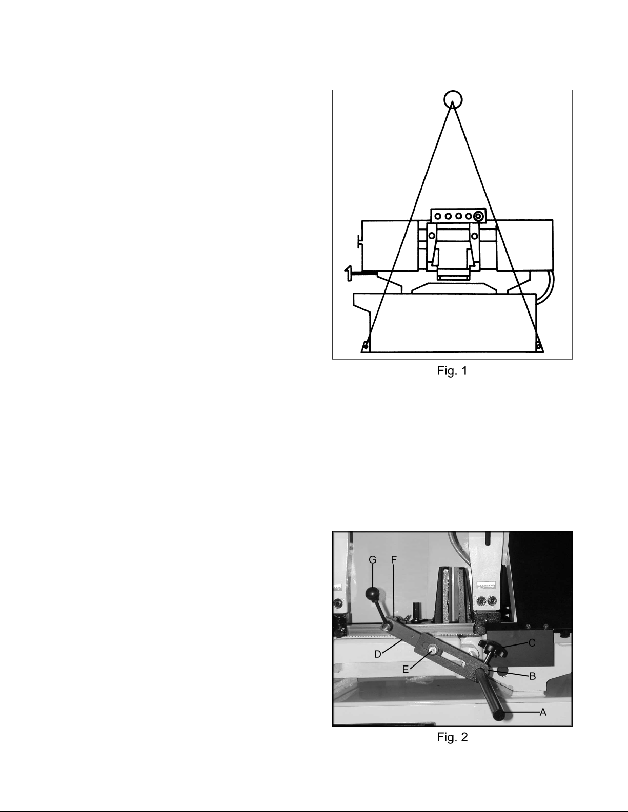
1. Using lifti ng str aps of adequate lifting
capacity, that are isolated from the
bandsaw's finished surfaces, lift mac hine
and place in desired location. See Figure 1
for strap plac em ent.
2. Install four leveling bolts with lock nuts on
both sides of the base.
3. Place a level on the bed surface and check
side to side and front t o bac k.
4. Adjust leveling screws until machine is level
in both directions and tighten locking nuts.
Assembly
1. Insert stop rod (A, Fig. 2) i nto t he base
below the vise. Plac e stop br ac k et (B, Fig.
2) onto stop rod and tight en loc k k nob ( C,
Fig. 2). Attach the connec ting plate (D, Fig.
2) to stop bracket with hex c ap bolt and
washer (E, Fig. 2), and tighten. Attach the
work stop (F, Fig. 2) t o the connec ting plate
with lock handle (G, Fi g. 2), and tighten.
Page 6

6
2. Slide the tensioning handle (A, Fig.3) ont o
the shaft and tighten the hex socket set
screw.
Electrical Connections
WARNING
All electrical connections must be done by a
qualified el ectrician! Failure to comply may
resul t in serious injur y !
WARNING
Disconnect machine from the power source
before changing any volt age components!
Failure to compl y may cause seri ou s in ju ry!
The HBS-1321W bandsaw is rated at 230/460V,
3Ph. and is prewired 230 volt from the factory.
Confirm power source available at the saw's
location is the sam e as the saw is wired. To
switch the HBS-1321W from 230V to 460V, t he
following items will have to be changed:
Bandsaw must always be properly grounded.
• Main Motor: Follow diagram inside junction
box cover.
• Coola nt Pum p: Follow diagram inside
junction box c ov er.
• Control Transformer: Open electrical
panel on rear of base and switch only the
one 230V primary wire on t r ansformer to the
460V position.
• Hydraulic Pump: Remove access panel
and follow diagram inside junction box
cover.
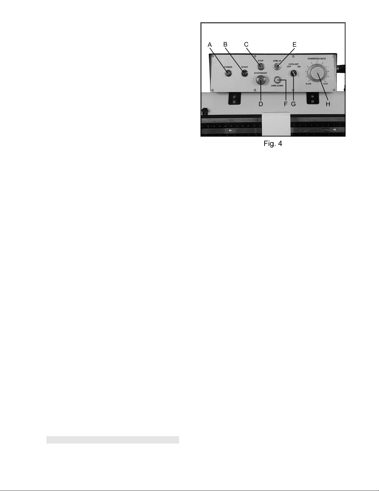
Controls (figure 4)
A. Power Indicator Light: Lit whenever
machine has power.
B. Start Button: Depress to start bandsaw.
Will not work if emergenc y butt on is
depressed.
C. Stop Button: Depress to stop bandsaw.
D. Emergency Stop Button: Depress to
immediately stop all machine functions.
E. Arm Up Button: Depress to raise arm.
Page 7
7
F. Arm Down Button: Depress to lower arm.
G. Coolant Switch: Turn arrow to ON starting
flow of coolant. Turn arr ow to OFF stopping
flow of coolant. Blade m ust be ci r c ulating
for coolant pump to work.
H. Downfeed Rate Knob: Turn clockwise to
increase down feed rate. Turn counter-
clockwise to decr ease do wn feed rate. See
adjusting feed rate page 9.
Prior to Operation
1. All JET bandsaws are designed and
intended for use by pr oper ly trained and
experienced personnel only. If you are not
familiar with the proper and safe operation of
a bandsaw, do not use until pr oper training
and knowledge have been obtained.
2. Check blade toot h di r ection matches
diagram on blade gui des.
3. Check to see that blade is properly seated
on wheels after applying correct tension
(approximately 25,000 lbs.).
4. Check blade guides f or pr oper adjustments.
See guide adjustm ents, page 11.
5. Position sli ding blade guide arms as close to
workpiece as possible.
6. Select proper speed and feed rate for
material being c ut. See speed selection
chart found in the enclosed "Guide to
Bandsawing" booklet supplied with thi s saw.
7. Material to be cut must be securely held in
the vise. See vi se adjustment page 8.
8. Check to see that coolant level is adequate
and turn on coolant pump if material to be
cut requir es it. See cool ant pump page 13.
9. Do not start cut on a sharp edge.
Page 8
8
WARNING
Disconnect machine from the power source
before adju sting or changi ng vise po sition!
Failure to compl y may cause seri ou s in ju ry!
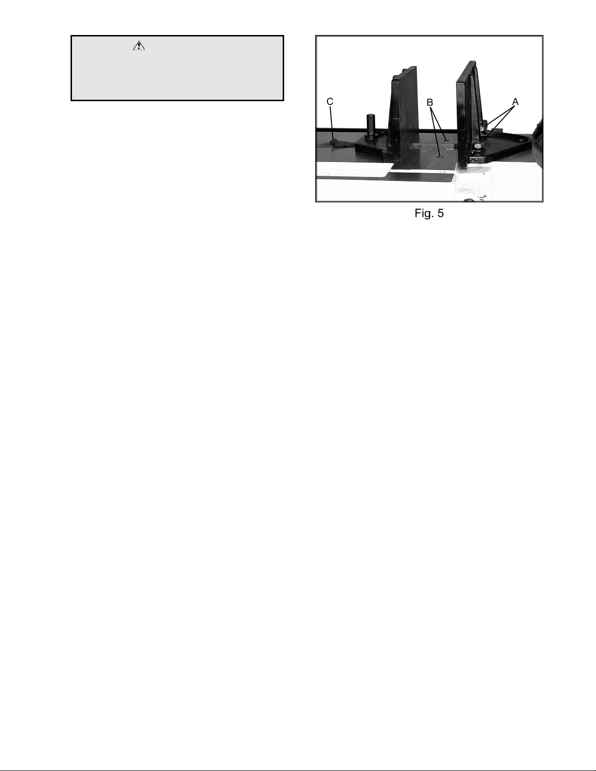
Adjusting Vise Square to the Blade
Position A
1. Place a machinist' s square on the bed
against the blade and the vise. The square
should lie along the entire length of the vise
and blade without a gap.
2. If adjustm ent is necessary, loosen bolts (A,
Fig. 5) holdi ng the vise and adjust vise so
square lines up properl y . Tighten bolts.
3. You may want to perform a test cut. Cut off
the end of the stock. Make anot her cut so
that you have an accurat e sect ion to
measure. Measure thic k ness wit h c alipers.
Adjusting Vise for Miter Cuts
Position B
1. Move the vi se into the second set of
threaded holes (B, Fig. 5) by removing hex
cap bolts (A, Fig. 5).
2. When angle has been set ti ghten bolts.
3. Adjust other jaw.
4. There is an angle label on the backside of
the bed. This is for ref er enc e only. Chec k
angles with a machi nist’s prot r ac tor.
For your own safety: only use position B for
miter cuts. Vise square to the blade, in position
B would expose more of the blade, ri ght of the
vise, than is necessary for the cut.
Positioning Vise
To position the m ov eable v ise:
1. Pull up on the rack block (C, Fig. 5).
2. Move vise to desired l oc ation by sliding
along bed.
3. Tighten vi se by turning handwheel, found at
the left end of the bed, cloc k wise.
4. Loosen vise by turning handwheel counter-
clockwise so you can pull up on the rack
block.
Page 9

9
Changing Blade Speeds
Adjust the vari able blade speed only while the
machine is running. The dial (A, Fig. 6) sticking
out of the belt cover (right side) controls the
variable speeds between 66 F P M to 264 F PM.
Semi-Automatic Arm
Preset the height, which the arm stops when it
raises automati c ally. The height the arm raises
depends upon the piece you want to cut. The
limit switch is l owered or r aised by loosening a
locking handl e ( A, Fig. 7). Tight en the locking
handle when the limit switc h has been properly
adjusted.
Automatic Shut-Off
The blade will stop after the material has been
cut, and the arm reaches it s l owest position.
The arm will automatically rise to the preset
height.
Adjusting Feed Rate
Rate of downfeed is adjusted by turning the
downfeed knob on the contr ol panel. Rate of
feed is important to bandsaw performance;
excessive pressure may break the blade or stall
the saw. Insufficient pressure rapidly dulls the
blade.
Material c hips or shavi ngs are t he best indicator
of proper speed and downfeed. The ideal chip
is thin, tightly curled, and warm to the touch.
Chips that range from golden brown to black
indicate excessive force. Blue chips indicat e
extreme heat from too high a band speed, which
will shorten blade life. Thin or powdered chips
indicate insuff icient downfeed rate.
A detailed explanation on feed rate can be found
in the enclosed "Guide to Band Sawing"
published by Ameri c an S aw and Manufacturing
Company. Reprinted by permission.
Page 10

1
Changing Blades
WARNING
Disconnect machine from the power source
before making any adjust ments or repairs!
Failure to compl y may resul t in seri ou s
injury!
1. Raise the saw arm approximately 6".
2. Disconnect machine from power source.
3. Open both wheel covers and clean chips out
of both wheel housings. Loosen lock knobs
and remove upper and lower bl ade guar ds.
4. Release blade tension by turning blade
tensioning handwheel (A, Fig. 8) counterclockwise until blade is free.
5. Loosen lock handle and slide left blade
guide arm (B, Fig. 8) to the right as far as
possible.
6. Remove old blade fr om both wheels and out
of each blade guide. Caution: Even dull
blades are sharp to the skin! Use extra
caution handli ng bandsaw blades!
7. Install a new blade making sure teeth are
pointed downward in t he pr oper c utt ing
direction.
8. Position blade on wheels and tighten just
enough to hold blade on wheel s. M ak e sure
back of blade rests lightly against the wheel
flange of both wheels. T wist blade slightly to
allow it to slip into guides.
9. Tension blade t o appr oximately 25,000 lbs.
Blade tension is i ndic ated on the tension
wheel shaft housing (left side).
10. Install all guards, cl ose covers and fasten
securely. Connect machine to power and
run freely for approximately two minutes.
11. Turn power off and r e- c hec k blade tension
and wire brush adjustment. If further
adjustment is necessary, disconnect saw
from power source, make adjustments,
and re-connect t o power.
0
Page 11

1
Guide Roller Adjustment
The bearings come pre- adjusted from the
factory. If adjustm ent is needed follow the below
steps:
1. Disconnect machine from the power
source.
2. Loosen two hex socket cap screws (A, Fig. 9).
3. Move guide seat (B, Fi g. 9) up or down until
an approximate clearance of .003" between
blade and bearing is obtained, (C, Fig. 9).
4. Tighten two hex socket cap screws (A, Fig. 9).
5. Adjust the ecc entric bearings (A, Fig. 10) by
loosening hex sock et cap screw (B, Fig. 10)
about one full turn.
6. With a 19mm wrench turn hex nut (C, Fig.
10) until the ball bearings are approximately
.003”. Note: Do not pinch the blade.
7. Tighten the hex socket cap screw (B, Fig.
10) while holding the hex nut (C, Fig. 10) in
place.
8. Repeat for other bl ade guide assembly.
9. Connect machine to power source.
Blade Guide Adjustment
The blade guides com e pr e- adjusted from the
factory. If adjustm ent is needed follow the below
steps:
1. Disconnect machine from the power
source.
2. Adjust spring loaded blade guide (A, Fig. 11)
by loosening or ti ghtening the guide
adjustment screw (B, Fig. 11).
3. The blade guide should place a light
pressure on the blade.
4. Connect machi ne to t he power source.
1
Page 12

1
Blade Tracking Adjustment
Since tracking c an only be adjusted while
machine is running, it is suggested that this
adjustment be accomplished by qualified
personnel that are familiar with this type of
adjustment and the dangers associated with it.
Blade tracking has been set at the factory and
should require no adjustment. If a tracking
problem occur s, adjust the machine as follows:
WARNING
Tracking adju st ment is done with the wheel
covers open to observe the blade. Use
extreme caution so as not to come into
contact with the blade!
1. Raise saw arm to its highest position.
2. Locate tracki ng adjustment plate on the
backside of the idle wheel.
3. Loosen the three bolts (A , Fig. 12) located
on the top of the tracking nuts.
4. Tracking adj ustm ent is accomplished by
either loosening or tightening three adj usting
nuts (B, Fig. 12).
5. Tracking i s set properly when the back of
the blade lightly touches the wheel flange.
Note: over-tracking (allowing blade back to
rub hard against wheel flange) will damage
the blade wheels and blade.
6. Tighten loc ki ng bolts (A) once proper
tracking i s completed.
Lubrication and Gearbox
All ball beari ngs are perm anently lubricated and
sealed. They requir e no further lubrication.
The gearbox lubri c ant should be changed after
the first 3 mont hs of operation. Use Mobil SHC
634, or equivalent . Change lubricant from then
on every year.
To check level of gear box lubr ic ant, place arm
in down position and allow a few minutes to
pass so that oil drains down. Check level in
sight glass on side of gear casing. Cor r ect lev el
is the dot in the middl e of sight glass.
2
Page 13

1
To change gear box lubricant:
1. Disconnect machine from the power
source.
2. Remove drain plug and allow lubricant to
drain complet ely . T he drai n plug is l oc ated
on lower front of gear case under right
wheel cover. Remove dr ain plug with a hex
wrench.
3. Reinstall drain plug.
4. Remove filler cap and fill gearbox with Mobil
SHC 634 until level r eac hes dot in mi ddle of
sight glass.
5. Reinstall filler cap.
6. Use Mobil DTE Oil Heavy Medium to
lubricate all other moving parts as needed.
Hydraulic Pump
If you need to add hydraulic fluid to the tank
remove cap (A, Fig. 13). Add Mobil DTE 24
until the black ball floats to the full positi on.
Coolant Pump
The coolant tank should be filled with 6 gallons
of a cutting cool ant. Fill by pouri ng c oolant into
the chip tray. Add cool ant in the same manner
when coolant is low. To drain coolant remove
hex cap screw (A, Fig. 14). Follow all coolant
manufacturer’s instructions for safety, mixing
disposal, etc.
The spray nozzle (B, Fig. 14) enabl es the user
to wash chips out of the way. Ther e are thr ee
ball valves that control the coolant distri bution to
the spray nozzle and eac h blade guide.
Replacing the Variable Speed Belt
Disconnect the machine from the power source.
Take the belt cover off by remov ing the knob
and washer. Loosen tension on the belt by
turning the variable speed dial (A, Fig. 15) to the
lowest setting. This will allow you to remove the
belt (B, Fig. 15). When installing the new belt
turn the pulley by hand while increasing variable
speed dial setting. After running the machine
additional adjustment of the variabl e speed di al
may be needed.
3
Page 14

1
Bed and Base Assembly
4
Page 15

1
Parts List for the JET HBS-1321W Bandsaw
Bed and Base Assembly
Index Part
No. No. Description Size Qty.
1..........1321W-01 .................................Base......................................... ...............................................1
2..........TS-1492061..............................Hex Cap Bolt.............................M12x65...................................4
3..........TS-1540081..............................Hex Nut.....................................M12......................................... 4
4..........1321W-04 .................................Coolant Pump...........................1/6HP...................................... 1
4-1.......1321W-04-1..............................Cross Point Screw.....................M6x16 .....................................2
4-2.......1321W-04-2..............................Spring Washe r..........................M6 ..........................................2
4-3.......1321W-04-3..............................Flat Washer...............................M6 ..........................................2
5..........TS-1524041..............................Set Screw.................................M8x16.....................................2
6..........1321W-06 .................................Coolant Tank Cover.................. ...............................................1
6-1.......TS-1550041..............................Washer..................................... M6 ..........................................1
6-2.......TS-1503031..............................Hex Socket Cap Scre w ..............M6x12.....................................1
6-3.......TS-1551041..............................Spring Washer..........................M6 ..........................................1
7..........1321W-07 .................................Bed........................................... ...............................................1
7-1.......1321W-07-1..............................Hex Cap Bolt.............................M12x50...................................4
7-2.......1321W-07-2..............................Spring Washe r..........................M12.........................................4
8..........1321W-08 .................................Connector ................................. ...............................................1
8-1.......1321W-08-1..............................Hose Fitting............................... ...............................................2
8-2.......1321W-08-2..............................Hose Clamp.............................. ...............................................6
8-3.......1321W-08-3..............................Hose.........................................3/8”x1200................................1
8-4.......1321W-08-4..............................On/Off Valve............................. ...............................................3
8-5.......1321W-08-5..............................Hose.........................................3/8”x2800................................1
8-6.......1321W-08-6..............................Hose Fitting............................... ...............................................1
8-7.......1321W-08-7..............................Coolant Nozzle.......................... ...............................................1
8-8.......1321W-08-8..............................Connector ................................. ...............................................1
8-9.......1321W-08-9..............................Fitting........................................ ...............................................1
9..........1321W-09 .................................Coolant Gauge.......................... ...............................................1
9-1.......TS-1491041..............................Pan Head Screw .......................M10x30...................................2
9-2.......TS-1550071..............................Washer..................................... M10.........................................2
9-3.......TS-1540071..............................Hex Nut.....................................M10.........................................2
10........1321W-10 .................................Drain Plug................................. ...............................................1
11........1321W-11 .................................Front Door w/Latch.................... ...............................................1
12........1321W-12 .................................Hinge Pin.................................. ...............................................2
13........1321W-13 .................................Panel Cover .............................. ...............................................1
13-1.....1321W-13-1..............................Round Cross Cap Screw ...........M6x8.......................................4
14........1321W-14 .................................Electrica l Panel Plate ................ ...............................................1
14-1.....1321W-14-1..............................Knob......................................... ...............................................1
14-2.....1321W-14-2..............................Hinge Pin .................................. ...............................................2
14-3.....1321W-14-3..............................Hex Nut.....................................M6 ..........................................1
15........1321W-15 .................................Lock Knob................................. ...............................................1
16........1321W-16 .................................Stop Bracket............................. ...............................................1
16-1.....1321W-16-1..............................Connecting Plate....................... ...............................................1
16-2.....1321W-16-2..............................Lock Washer............................. ...............................................1
16-3.....1321W-16-3..............................Hex Cap Bolt............................. ...............................................1
17........1321W-17 .................................Stop Rod................................... ...............................................1
18........1321W-18 .................................Lock Handle.............................. ...............................................1
19........1321W-19 .................................Work Stop................................. ...............................................1
20........1321W-20 .................................Lead Screw Seat....................... ...............................................1
20-1.....TS-1504061 ..............................Hex Socket Cap Scr e w ..............M8x30.....................................2
20-2.....TS-1551081 ..............................Spring Washer..........................M8 ..........................................2
20-3.....TS-1550061 ..............................W asher.....................................M8 ..........................................2
5
Page 16

1
21........1321W-21 .................................Handle Wheel Assembly ........... ...............................................1
21-1.....TS-0270031 ..............................Set Screw.................................5/16"x3/8"................................2
21-2.....1321W-21-2..............................Handle ...................................... ...............................................1
22........1321W-22 .................................Rack......................................... ...............................................1
23........1321W-23 .................................Lead Screw Seat....................... ...............................................1
23-2.....TS-1504041 ..............................Hex Socket Cap Scr e w ..............M8x20.....................................2
24........1321W-24 .................................Lead Screw............................... ...............................................1
24-1.....1321W-24-1..............................Key ........................................... ...............................................1
25........1321W-25 .................................Slide Bracket............................. ...............................................1
26........1321W-26 .................................Vise Jaw - Left........................... ...............................................1
26-1.....TS-1492041 ..............................Hex Cap Bolt.............................M12x40...................................1
26-2.....1321W-26-2..............................Locking Bolt ..............................M12x45...................................1
26-3.....TS-1551081 ..............................Spring Washer..........................M12.........................................2
26-4.....TS-1550061 ..............................W asher.....................................M12x35x5W............................1
27........1321W-27 .................................Rack Block................................ ...............................................1
28........TS-1523021..............................Set Screw.................................M6x8.......................................1
29........1321W-29 .................................Pin............................................ ...............................................1
30........1321W-30 .................................Needle Bearing .........................CB3020...................................2
31........1321W-31 .................................Vise Jaw - Right........................ ...............................................1
31-1.....1321W-31-1..............................Hex Cap Bolt.............................M16x50...................................1
31-2.....1321W-31-2..............................Hex Cap Bolt.............................M16x40...................................1
31-3.....1321W-31-3..............................Spring Washer..........................M16.........................................2
31-4.....1321W-31-4..............................W asher.....................................M16x35x5W............................1
32........1321W-32 .................................Pivot Shaft................................. ...............................................1
32-1.....TS-1492001 ..............................Hex Cap Bolt.............................M12x20...................................2
32-2.....TS-1550081 ..............................W asher.....................................M12.........................................2
33........1321W-33 .................................Pivot Bracket............................. ...............................................1
33-1.....1321W-33-1..............................Spacer...................................... ...............................................1
34........1321W-34 .................................Spring....................................... ...............................................1
35........1321W-35 .................................Support Bracket Seat ................ ...............................................1
36........1321W-36 .................................Pivot Support Shaft ................... ...............................................1
36-1.....1321W-36-1..............................C-Clip........................................S22.........................................1
37........1321W-37 .................................Motor........................................3HP, 3Ph ................................1
37-1.....1321W-37-1..............................Key ...........................................8x7x50....................................1
38........TS-1550041..............................Flat Washer...............................M6 ..........................................2
39........1321W-39 .................................Hex Cap Bolt.............................M10x55 ...................................4
39-1.....TS-1550071 ..............................Flat Washer...............................M10.........................................4
39-2.....TS-1541071 ..............................Spring Washer..........................M10.........................................4
39-3.....TS-1540071 ..............................Hex Nut.....................................M10.........................................4
40........TS-1492051..............................Hex Cap Bolt.............................M12x50...................................3
40-1.....TS-1551081 ..............................Spring Washer..........................M12.........................................3
40-2.....TS-1550081 ..............................W asher.....................................M12.........................................3
41........1321W-41 .................................Switch Mounting Plate............... ...............................................1
42........TS-1551041..............................Spring Washer..........................M6 ..........................................2
43........TS-1482021..............................Hex Cap Bolt.............................M6x12.....................................2
44........1321W-44 .................................Cross Point Screw.....................M5x35.....................................8
44-1.....1321W-44-1..............................Spring Washer..........................M5 ..........................................8
45........1321W-45 .................................Limit Switch...............................5101........................................1
45-1.....1321W-45-1..............................Roller Limit Switch.....................5102........................................1
46........1321W-46 .................................Adjusting Bracket...................... ...............................................1
46-1.....1321W-46-1..............................Scale Plate................................ ...............................................1
46-2.....1321W-46-2..............................Rivet ......................................... ...............................................2
47........1321W-47 .................................Cylinder Support Rod................ ...............................................1
47-1.....1321W-47-1..............................C-Clip........................................S32.........................................2
47-2.....1321W-47-2..............................C-Clip........................................S28.........................................1
48........1321W-48 .................................Cylinder Cover .......................... ...............................................1
49........1321W-49 .................................Spring....................................... ...............................................1
6
Page 17

1
50........1321W-50 .................................Retaining P in............................. ...............................................1
51........1321W-51 .................................Cylinder Assembly..................... ...............................................1
51-1.....1321W-51-1..............................Holder....................................... ...............................................1
52........1321W-52 .................................Cylinder Pin............................... ...............................................1
53........1321W-53 .................................Top Mounting Plate................... ...............................................1
54........TS-1492031..............................Hex Cap Bolt.............................M12x35...................................2
55........TS-1551081..............................Spring Washer..........................M12.........................................2
56........1321W-56 .................................Plate......................................... ...............................................1
56-1.....TS-1482021 ..............................Hex Cap Bolt.............................M6x12.....................................2
56-2.....TS-1551041 ..............................Spring Washer..........................M6 ..........................................2
56-3.....TS-1550041 ..............................Flat Washer...............................M6 ..........................................2
57........1321W-57 .................................Switch Mounting Plate............... ...............................................1
58........TS-1503011..............................Hex Socket Cap Scr e w ..............M6x8.......................................2
59........TS-1504051..............................Hex Socket Cap Scr e w ..............M8x25.....................................6
60........TS-1551081..............................Spring Washer..........................M8 ..........................................2
61........1321W-61 .................................Handle ...................................... ...............................................1
61-1.....TS-1550071 ..............................W asher.....................................M10.........................................1
62........1321W-62 .................................Hydraulic Pump Motor............... ...............................................1
62-1.....1321W-62-1..............................Pump........................................ ...............................................1
62-2.....1321W-62-2..............................Solenoid Valv e.......................... ...............................................1
62-3.....1321W-62-3..............................Hydraulic Fill Cap ...................... ...............................................1
63........1321W-HPCA ...........................Hydraulic Pump Complete Assembly.........................................1
64........1321W-64 .................................Scale......................................... ...............................................1
65........1321W-65 .................................Rivet......................................... ...............................................2
66........TS-1503031..............................Hex Socket Cap Sc re w ..............M6x12.....................................2
67........1321W-67 .................................Plate......................................... ...............................................2
68........1321W-68 .................................Roller Seat................................ ...............................................2
68-1.....TS-1525021 ..............................Set Screw.................................M10x12...................................2
69........1321W-69 .................................Support Roller........................... ...............................................2
69-1.....BB6004ZZ.................................Ball Bearing...............................6004ZZ ...................................2
70........1321W-70 .................................Rod........................................... ...............................................1
71........1321W-71 .................................Knob......................................... ...............................................2
72........TS-1523021..............................Set Screw.................................M6x8.......................................2
73........1321W-73 .................................Terminal Strip............................ ...............................................2
74........1321W-74 .................................Magnetic Switch (w/Overload)... ...............................................1
74-1.....1321W-74-1..............................Magnetic Switch........................ ...............................................1
74-2.....1321W-74-2..............................Magnetic Switch........................ ...............................................1
75........1321W-75 .................................Relay........................................ ...............................................1
75-1.....1321W-75-1..............................Relay ........................................ ...............................................1
76........1321W-76 .................................Transformer.............................. ...............................................1
77........1321W-77 .................................Fuse Case................................. ...............................................1
77-1.....1321W-77-1..............................Fuse (3A).................................. ...............................................2
7
Page 18

1
Arm Assembl y
8
Page 19

1
Arm Assembl y
Index Part
No. No. Description Size Qty.
8-1.......1321W-08-1..............................Hose Fitting............................... ...............................................2
8-2.......1321W-08-2..............................Hose Clamp.............................. ...............................................6
8-4.......1321W-08-4..............................On/Off Valve............................. ...............................................3
80........1321W-80 .................................Blade Wheel Cover - R.............. ...............................................1
80-1.....1321W-80-1..............................Hinge Pin .................................. ...............................................4
81........1321W-81 .................................Brush Cover.............................. ...............................................1
81-1.....TS-1482021 ..............................Hex Cap Bolt.............................M6x12.....................................2
81-2.....TS-1551041 ..............................Spring Washer..........................M6 ..........................................2
81-3.....TS-1550041 ..............................Flat Washer...............................M6 ..........................................2
81-4.....TS-1540041 ..............................Nut............................................M6 ..........................................2
82........1321W-82 .................................Handle ...................................... ...............................................2
82-1.....1321W-82-1..............................Cross Point Screw.....................M6x16.....................................4
82-2.....1321W-82-2..............................W asher.....................................M6 ..........................................4
83........1321W-83 .................................Blade Wheel Cover - L .............. ...............................................1
84........1321W-84 .................................Drive Wheel .............................. ...............................................1
84-1.....1321W-84-1..............................Hex Cap Bolt.............................M12x20...................................1
84-2.....1321W-84-2..............................W asher.....................................M12.........................................1
85........1321W-85 .................................Saw Blade.................................1-1/4” x .042” x 161-1/2”..........1
86........1321W-86 .................................Knob......................................... ...............................................8
87........TS-1491041..............................Hex Cap Bolt.............................M10x30...................................4
88........TS-1551071..............................Spring Washer..........................M10.........................................4
89........TS-1492031..............................Hex Cap Bolt.............................M12x35...................................4
90........TS-1551081..............................Spring Washer..........................M12.........................................4
91........1321W-91 .................................Blade Guard.............................. ...............................................1
92........1321W-92 .................................Blade Wheel Box Assembly ....... ...............................................1
93........1321W-93 .................................Connector ................................. ...............................................1
93-1.....1321W-93-1..............................Hex Socket Cap Scr e w ..............M6x20.....................................2
93-2.....1321W-93-2..............................Hose......................................... ...............................................1
93-3.....1321W-93-3..............................Hose......................................... ...............................................1
94........1321W-94 .................................Gear Box Assembly................... ...............................................1
94-1.....1321W-94-1..............................Key ...........................................12x8x32..................................1
94-2.....1321W-94-2..............................Key ...........................................7x7x40....................................1
94-3.....TS-1525041 ..............................Set Screw.................................M10x12...................................2
95........1321W-95 .................................Plate......................................... ...............................................1
95-1.....TS-1482021 ..............................Hex Cap Bolt.............................M6x12.....................................2
95-2.....TS-1551041 ..............................Spring Washer..........................M6 ..........................................2
95-3.....TS-1550041 ..............................W asher.....................................M6 ..........................................2
96........1321W-96 .................................Pulley Cov er.............................. ...............................................1
97........1321W-97 .................................Input Pulley ............................... ...............................................1
98........1321W-98 .................................Belt...........................................1922V443 ...............................1
99........1321W-99 .................................Output Pul ley Assembly ............ ...............................................1
100......1321W-100...............................Cover Plate............................... ...............................................1
100-1...TS-1490021 ..............................Hex Cap Bolt.............................M8x16.....................................4
100-2...TS-1551081 ..............................Spring Wash er..........................M8 ..........................................3
100-3...TS-1550061 ..............................Washer.....................................M8 ..........................................6
101......1321W-101...............................Shaft......................................... ...............................................1
101-1...1321W-101-1............................Knob......................................... ...............................................1
101-2...1321W-101-2............................Washer.....................................5/16” .......................................1
101-3...1321W-101-3............................Nut............................................5/16” .......................................1
101-4...1321W-101-4............................Spring Washer..........................5/16” .......................................1
102......1321W-102...............................Guide Bracket - L...................... ...............................................1
9
Page 20

2
103......TS-1524041..............................Set Screw.................................M8x16.....................................4
104......1321W-104...............................Blade Guide A ssembly - L........... ...............................................2
105......1321W-105...............................Blade Guide A ssembly - R........... ...............................................2
106......1321W-106...............................Connector ................................. ...............................................2
107......1321W-107...............................Cu Connector............................ ...............................................2
108......TS-1490051..............................Hex Socket Cap Scre w ..............M8x30.....................................4
109......BB608Z..................................... Ball Bearing...............................608Z .......................................4
110......1321W-110...............................Guide Bracket - R...................... ...............................................1
111......TS-1550061..............................Flat Wash er...............................M8 ..........................................4
112......BB6201RS................................Ball Bearing...............................6201RS...................................8
113......1321W-113...............................Sleeve....................................... ...............................................2
113-1...1321W-113-1............................Eccentric Sleev e ....................... ...............................................2
114......TS-1551081..............................Spring Washer..........................M8 ..........................................4
115......TS-1490081..............................Hex Socket Cap Scre w ..............M8x45.....................................4
116......1321W-116...............................Adjusting Knob .......................... ...............................................2
117......1321W-117...............................Small Shaft................................ ...............................................2
118......1321W-118...............................Spring....................................... ...............................................2
119......1321W-119...............................Hex Socket Cap Scr e w ..............M16x12...................................2
120......1321W-120...............................Idle Blade Wheel....................... ...............................................1
121......1321W-121...............................Jam Nut.................................... ...............................................1
122......1321W-122...............................Star Washer.............................. ...............................................1
123......1321W-123...............................Taper Roller Bearing .................30206......................................2
124......1321W-124...............................Spacer...................................... ...............................................1
125......1321W-125...............................Blade Guar d.............................. ...............................................1
125-1...TS-1482021 ..............................Hex Cap Bolt.............................M6x12.....................................2
125-2...TS-1551041 ..............................Spring Wash er..........................M6 ..........................................2
125-3...TS-1550041 ..............................Washer.....................................M6 ..........................................2
126......1321W-126...............................Adjusting Bracket Mount............ ...............................................2
127......1321W-127...............................Lock Block................................. ...............................................2
128......1321W-128...............................Handle ...................................... ...............................................2
129......TS-1550071..............................Washer.....................................M10.........................................2
130......TS-1505051..............................Hex Socket Cap Scre w ..............M10x40...................................4
131......TS-1551071..............................Spring Washer..........................M10.........................................4
132......TS-1550071..............................Washer.....................................M10.........................................4
133......TS-1550081..............................Hex Socket Cap Scre w ..............M12x25...................................2
134......TS-1524031..............................Set Screw .................................M8x10.....................................5
135......1321W-135...............................Scale Plate................................ ...............................................1
136......1321W-136...............................Cross Point Screw..................... ...............................................4
137......1321W-137...............................Slide Bracket............................. ...............................................1
138......1321W-138...............................Blade Brac k et - L....................... ...............................................1
139......TS-1492021..............................Hex Cap Bolt .............................M12x30...................................4
139-1...TS-1551081 ..............................Spring Wash er..........................M12.........................................4
140......1321W-140...............................Blade Brac k et - R...................... ...............................................1
141......1321W-141...............................Hex Nut.....................................M12.........................................1
142......1321W-142...............................Stop Support............................. ...............................................1
143......1321W-143...............................Spring....................................... ...............................................1
144......1321W-144...............................Pin ............................................ ...............................................2
145......1321W-145...............................Rubber Pad............................... ...............................................1
146......1321W-146...............................Stop Block................................. ...............................................1
147......1321W-147...............................Brass Wire Brus h...................... ...............................................1
147-1...TS-1482021 ..............................Hex Cap Bolt.............................M6x12.....................................2
147-2...TS-1551041 ..............................Spring Wash er..........................M6 ..........................................2
147-3...TS-1550041 ..............................Washer.....................................M6 ..........................................2
148......1321W-148...............................Bushing..................................... ...............................................1
149......1321W-149...............................Brush Bracket ........................... ...............................................1
149-1...TS-1482021 ..............................Hex Cap Bolt.............................M6x12.....................................2
0
Page 21

2
149-2...TS-1551041 ..............................Spring Wash er..........................M6 ..........................................2
149-3...TS-1550041 ..............................Washer.....................................M6 ..........................................2
150......1321W-150...............................Control Box............................... ...............................................1
150-1...TS-1482021 ..............................Hex Cap Bolt.............................M6x12.....................................4
150-2...TS-1551041 ..............................Spring Wash er..........................M6 ..........................................4
150-3...TS-1550041 ..............................Washer.....................................M6 ..........................................4
151......1321W-151...............................Control Panel ............................ ...............................................1
151-1...1321W-151-1............................Cross Point Screw.....................M5x10.....................................8
152......1321W-152...............................Downfeed Valve Assembly........ ...............................................1
153......1321W-153...............................Power Indicator Light................. ...............................................1
154......1321W-154...............................Start Button............................... ...............................................1
155......1321W-155...............................Stop Button............................... ...............................................1
156......1321W-156...............................Emergency Switch..................... ...............................................1
157......1321W-157...............................Arm Up Switch.......................... ...............................................1
158......1321W-158...............................Arm Down Switch...................... ...............................................1
159......1321W-159...............................On/Off Coolant Switch............... ...............................................1
160......1321W-160...............................Downfeed Control Knob ............ ...............................................1
160-1...TS-1523061 ..............................Set Screw.................................M6x20.....................................2
161......1321W-161...............................Extension Bar............................ ...............................................1
161-1...1321W-161-1............................Key ........................................... ...............................................1
162......1321W-162...............................Handle Base ............................. ...............................................1
162-1...1321W-162-1............................Handle ...................................... ...............................................2
163......1321W-163...............................Thrust Bearing...........................51106......................................1
164......1321W-164...............................Indicator Was h e r....................... ...............................................1
165......1321W-165...............................Spacer...................................... ...............................................1
166......1321W-166...............................Blade Wheel Bracket Shaft........ ...............................................1
166-1...1321W-166-1............................Cover........................................ ...............................................1
167......1321W-167...............................Slide Bracket............................. ...............................................1
168......1321W-168...............................Adjusting Nut............................. ...............................................1
168-1...TS-1523021 ..............................Set Screw.................................M6x8.......................................1
169......1321W-169...............................Slide Plate................................. ...............................................2
170......TS-1504041..............................Hex Socket Cap Scre w ..............M8x20.....................................6
170-1...TS-1551061 ..............................Spring Wash er..........................M8 ..........................................6
171......1321W-171...............................Extension Bracket..................... ...............................................1
171-1...1321W-171-1............................Sleeve.......................................M20x35 ...................................3
171-2...TS-1551081 ..............................Spring Wash er..........................M12.........................................3
171-3...1321W-171-3............................Hex Cap Bolt.............................M12x65...................................3
172......1321W-172...............................Blade Extension S c ale............... ...............................................1
172-1...1321W-172-1............................Cross Point Screw.....................M5x10.....................................2
173......1321W-173...............................Spring Support Shaft................. ...............................................1
174......1321W-174...............................Belleville Spring.........................W=2.5mm .............................16
175......1321W-175...............................Stop Flange............................... ...............................................1
175-1...1321W-175-1............................Set Screw .................................M8x20.....................................2
176......1321W-176...............................Limit Switch...............................1307........................................1
176-1...1321W-176-1............................Cross Point Screw.....................5/32”x1”................................... 2
176-2...TS-1550021 ..............................Washer.....................................M4 ..........................................2
176-3...TS-1540021 ..............................Nut (not shown).........................M4 ..........................................2
177......1321W-177...............................Cover........................................ ...............................................1
177-1...TS-1482021 ..............................Hex Cap Bolt.............................M6x12.....................................2
177-2...TS-1551041 ..............................Spring Wash er..........................M6 ..........................................2
177-3...TS-1550041 ..............................Washer.....................................M6 ..........................................2
178......1321W-178...............................Relief Bushing........................... ...............................................2
178-1...1321W-178-1............................Cover........................................ ...............................................1
179......1321W-179...............................Electrical Wire ..........................0.5/2Cx430cm.........................1
180A....1321W-180A.............................Eccentric Sleeve Assembly (#111,112,113-1,114,115) ..............2
180B....1321W-180B.............................Sleeve Assembly (#111,112,113,114,115).................................2
1
Page 22

2
............ 1321W-181B1...........................Laser Guide with Bracket (not shown) .......................................1
............ 1321W-181B2...........................Transformer with Power Cord (not shown).................................1
............ 1321W-181B3...........................Bracket for Laser Guide (not shown)..........................................1
Gear Reduce Box Assembly
Index Part
No. No. Description Size Qty.
1..........1321W-94-01 ............................Output Shaft Cover.................... ...............................................1
2..........TS-1482031..............................Hex Socket Cap Sc re w ..............M6x16.....................................4
3..........1321W-94-03 ............................Key...........................................12x8x35..................................1
4..........1321W-94-04 ............................Output Shaft.............................. ...............................................1
5..........1321W-94-05 ............................Oil Seal.....................................TC50X70X10 ..........................1
6..........1321W-94-06 ............................Taper Roller Beari ng .................30210......................................2
7..........1321W-94-07 ............................Worm........................................ ...............................................1
8..........1321W-94-08 ............................Key...........................................16x10x70................................1
9..........1321W-94-09 ............................Key...........................................7x7x50....................................1
10........1321W-94-10............................Oil Seal.....................................SC30x62x7.............................1
11........1321W-94-11............................C-Clip........................................R62.........................................1
12........1321W-94-12............................Taper Roller Bearing .................30206......................................2
13........1321W-94-13............................Drain Plug.................................1/4”PT.....................................1
14........1321W-94-14............................Gear Box................................... ...............................................1
15........1321W-94-15............................Wor m Shaft............................... ...............................................1
16........1321W-94-16............................Gasket...................................... ...............................................1
17........1321W-94-17............................Input S haft Cover...................... ...............................................1
18........TS-1504041..............................Hex Socket Cap Scr e w ..............M8x20.....................................4
19........1321W-94-19............................Clear Oil Glass..........................25 ...........................................1
20........1321W-94-20............................Fill Oil Plug................................3/8”PT.....................................1
21........TS-1551071..............................Spring Washer..........................M10.........................................6
22........TS-1491041..............................Hex Cap Bolt.............................M10x30...................................6
23........1321W-94-23............................Wor m Shaft Cover..................... ...............................................1
2
Page 23

2
Wiring Diagram
3
Page 24

2
Wiring Diagram Symbol Glossary
Symbol Description Part Number.
LS1 Cut off Limit Switch 1321W-45
LS2 Roller Limit S witch 1321W-45-1
SB1 Emergency Switch 1321W-156
SB2 Start Switch 1321W-154
SB3 Arm Down Switch 1321W-158
SB4 Arm Up Switch 1321W-157
SB5 Stop Switch 1321W-155
HL Power Indicator Light 1321W-153
TC Control Transformer 1321W-76
FU1 3A Fuse 1321W-77-1
FU2 3A Fuse 1321W-77
M1 Magnetic Switch (w/OL) 1321W-74
M2 Magnetic Switch 1321W-74-1
M3 Magnetic Switch 1321W-74-2
R1 Arm Up Relay 1321W-75
R2 Arm Down Relay 1321W-75-1
SA1 Coolant Pump On / Off Switch 1321W-159
SOL SOL Valve 1321W-152
4
 Loading...